EP2693610A1 - Motor mount - Google Patents
Motor mount Download PDFInfo
- Publication number
- EP2693610A1 EP2693610A1 EP13176403.7A EP13176403A EP2693610A1 EP 2693610 A1 EP2693610 A1 EP 2693610A1 EP 13176403 A EP13176403 A EP 13176403A EP 2693610 A1 EP2693610 A1 EP 2693610A1
- Authority
- EP
- European Patent Office
- Prior art keywords
- sleeve
- motor
- mount
- elements
- studs
- Prior art date
- Legal status (The legal status is an assumption and is not a legal conclusion. Google has not performed a legal analysis and makes no representation as to the accuracy of the status listed.)
- Withdrawn
Links
Images
Classifications
-
- H—ELECTRICITY
- H02—GENERATION; CONVERSION OR DISTRIBUTION OF ELECTRIC POWER
- H02K—DYNAMO-ELECTRIC MACHINES
- H02K5/00—Casings; Enclosures; Supports
-
- H—ELECTRICITY
- H02—GENERATION; CONVERSION OR DISTRIBUTION OF ELECTRIC POWER
- H02K—DYNAMO-ELECTRIC MACHINES
- H02K5/00—Casings; Enclosures; Supports
- H02K5/24—Casings; Enclosures; Supports specially adapted for suppression or reduction of noise or vibrations
-
- F—MECHANICAL ENGINEERING; LIGHTING; HEATING; WEAPONS; BLASTING
- F16—ENGINEERING ELEMENTS AND UNITS; GENERAL MEASURES FOR PRODUCING AND MAINTAINING EFFECTIVE FUNCTIONING OF MACHINES OR INSTALLATIONS; THERMAL INSULATION IN GENERAL
- F16F—SPRINGS; SHOCK-ABSORBERS; MEANS FOR DAMPING VIBRATION
- F16F1/00—Springs
- F16F1/36—Springs made of rubber or other material having high internal friction, e.g. thermoplastic elastomers
- F16F1/373—Springs made of rubber or other material having high internal friction, e.g. thermoplastic elastomers characterised by having a particular shape
- F16F1/376—Springs made of rubber or other material having high internal friction, e.g. thermoplastic elastomers characterised by having a particular shape having projections, studs, serrations or the like on at least one surface
-
- F—MECHANICAL ENGINEERING; LIGHTING; HEATING; WEAPONS; BLASTING
- F16—ENGINEERING ELEMENTS AND UNITS; GENERAL MEASURES FOR PRODUCING AND MAINTAINING EFFECTIVE FUNCTIONING OF MACHINES OR INSTALLATIONS; THERMAL INSULATION IN GENERAL
- F16F—SPRINGS; SHOCK-ABSORBERS; MEANS FOR DAMPING VIBRATION
- F16F15/00—Suppression of vibrations in systems; Means or arrangements for avoiding or reducing out-of-balance forces, e.g. due to motion
-
- F—MECHANICAL ENGINEERING; LIGHTING; HEATING; WEAPONS; BLASTING
- F16—ENGINEERING ELEMENTS AND UNITS; GENERAL MEASURES FOR PRODUCING AND MAINTAINING EFFECTIVE FUNCTIONING OF MACHINES OR INSTALLATIONS; THERMAL INSULATION IN GENERAL
- F16F—SPRINGS; SHOCK-ABSORBERS; MEANS FOR DAMPING VIBRATION
- F16F15/00—Suppression of vibrations in systems; Means or arrangements for avoiding or reducing out-of-balance forces, e.g. due to motion
- F16F15/02—Suppression of vibrations of non-rotating, e.g. reciprocating systems; Suppression of vibrations of rotating systems by use of members not moving with the rotating systems
-
- A—HUMAN NECESSITIES
- A47—FURNITURE; DOMESTIC ARTICLES OR APPLIANCES; COFFEE MILLS; SPICE MILLS; SUCTION CLEANERS IN GENERAL
- A47L—DOMESTIC WASHING OR CLEANING; SUCTION CLEANERS IN GENERAL
- A47L9/00—Details or accessories of suction cleaners, e.g. mechanical means for controlling the suction or for effecting pulsating action; Storing devices specially adapted to suction cleaners or parts thereof; Carrying-vehicles specially adapted for suction cleaners
- A47L9/22—Mountings for motor fan assemblies
-
- H—ELECTRICITY
- H02—GENERATION; CONVERSION OR DISTRIBUTION OF ELECTRIC POWER
- H02K—DYNAMO-ELECTRIC MACHINES
- H02K7/00—Arrangements for handling mechanical energy structurally associated with dynamo-electric machines, e.g. structural association with mechanical driving motors or auxiliary dynamo-electric machines
- H02K7/14—Structural association with mechanical loads, e.g. with hand-held machine tools or fans
- H02K7/145—Hand-held machine tool
Definitions
- the invention relates to a mount for a motor, preferably an electric motor.
- Electric motors are becoming increasingly sophisticated and modem designs are capable of ever higher rotational speeds.
- One such design of electric motor is a brushless DC motor as used by the applicant in its range of handheld vacuum cleaners and which is capable of being driven at rotational speeds in the region of 100000rpm.
- the invention provides a mount for an electric motor, the mount comprising a sleeve for receiving a motor, wherein the sleeve includes plurality of elements projecting from a surface of the sleeve, each of the plurality of elements including a vertex.
- Each of the elements therefore defines a single point of contact with a surrounding conduit or housing within which the motor is installed, in use.
- the point-contact engagement or interface the motor mount makes with an installation results in a significant reduction in the acoustic energy that is transmitted from the motor through the motor mount.
- the elements may take different forms, the important factor being the sharp vertex, point, or tip, the element defines in order to engage a surrounding housing.
- the elements or 'studs' are preferably conical since conical studs are in practice more straightforward to manufacture accurately.
- the studs could be pyramidal, prismatic or bi-conic for instance.
- the studs are right circular cones such that the axis of the cone passes through the apex/vertex and the centre of the circular base of the cone at right angles.
- the base of the cone may be a shape other than a circle, polygonal for example, and the axis need not pass through the centre of the base, or through the base at right angles.
- the vertex angle of the studs may be in the range of 40 and 80 degrees, although it is preferred that the vertex angle is about 60 degrees. However, depending on the technical application in which the motor mount is to be used, a wide range of vertex angles may be useful, in the range of 20 to 170 degrees.
- the most benefit is to be obtained from configuring the sleeve so that the elements/studs project only from the outer surface of the sleeve, whilst the inner surface is smooth so as to contact uniformly with the underlying casing of a motor within the sleeve.
- the invention does not exclude features such as mounting lugs, or even point studs being formed either solely on the inner surface of the sleeve, or even in combination with studs on the outer surface of the sleeve.
- the motor mount is formed from a polymeric material
- the currently preferred material is polyurethane rubber having a hardness of 40 Shore A.
- other polymeric materials would also achieve noise reduction benefits and particularly with hardness characteristics between 30 and 60 Shore A.
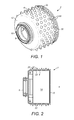
- a motor mount 2 comprises a generally cylindrical sleeve 4 including first and second open ends 6, 8.
- the first open end 6 is shown to the right of the figures, and the diameter of the first open end 6 is substantially the same as the diameter of the sleeve 4.
- the second open end 8 is shown to the left of the figures.
- the second open end 8 is formed by a central boss 10 that projects from a flange 12 extending inwardly from the cylindrical wall of the sleeve 4.
- the second open end 8 has a smaller diameter than the first open end 6 and, in this embodiment, is about half the size of the first open end 6.
- the configuration of the sleeve 4 defines a chamber 14, as shown in Figure 2 , into which is received an electric motor 16.
- the motor 16 is received within the chamber 14 through the first, relatively wide, open end 6 of the sleeve 4.
- the sleeve 4 is a flexible material such as a polymer so that the sleeve 4 can be pulled over the external surface of the motor 16, and stretched if necessary, so that an inner surface 23 of the sleeve 4 forms a tight fit around the motor 16, like a sock.
- the inner surface 23 is smooth in this embodiment so as to conform closely to the cylindrical outer profile of the motor 16.
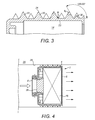
- Figure 2 illustrates the interior of the motor mount 2 without its motor and Figure 4 shows a cross section through the motor mount 2 with an electric motor shown in situ.
- the electric motor 16 is shown schematically for simplicity and so as not to obfuscate the details of the motor mount 2.
- the motor is not central to the inventive concept and so will not be described in detail.
- the sleeve 4 is provided with a noise attenuating means.
- the noise attenuating means takes the form of a plurality of projecting elements or 'studs' 20 that are spaced around an outer surface 22 of the sleeve wall. Note that only two of the studs are labeled for clarity.
- the studs 20 are right circular cones, each of which defines a sharp point, also referred to as a vertex 24, as labeled in Figure 3 , that are directed away from the sleeve 4.
- the studs 20 therefore provide sharp points distributed radially about the surface of the sleeve 4 to serve as an interface with an adjacent housing into which the motor and motor mount is installed.
- Figure 4 shows the motor mount 2 installed in a conduit or housing 26 and it will be seen that the studs 20 engage an inner surface 28 of the housing.
- the technical principle of the studs 20 is based on minimizing the area of contact that between the motor 16 and the housing 26 in order to reduce the transmission of energy from the motor 16 to the housing 26.
- the studs 20 provide a secure mounting for the motor 16 therefore protecting it from shocks that may occur during use, for example, by a user dropping the device in which the motor is installed.
- the number of elements in a row alternates between four elements and five elements. In total there are 126 elements in this embodiment, although the skilled person will appreciate that this figure is exemplary only. In selecting the number of elements for such a motor mount, a balance is to be struck between minimizing the number of elements in order to achieve a small area of contact between the mount and an adjacent housing, and providing sufficient elements to support the motor so that it is protected from shocks, in use.
- the electric motor 16 is equipped with an impeller 28 to act as a fluid mover, the air flow being depict by way of arrows.
- impeller 28 to act as a fluid mover
- Such an arrangement may have particular application to devices which require high speed air flows, such as vacuum cleaners, hair dryers, and fans.
- the specific embodiment is only exemplary and that the motor mount is applicable to any apparatus in which a motor needs to be installed in a close conforming housing, whether or not the motor is coupled to an impeller.
- Figure 3 shows a region of the motor mount 2 in Figure 2 in a larger scale so that details of the conical elements may be seen more clearly.
- all of the elements are identical and have a height 'L' of 3mm and a vertex angle ⁇ of 60°.
- the selection of vertex angle is a compromise: if the vertex angle is too small (a relatively narrow cone) the cone tip 24 may flex when under load, and if the vertex angle is too large (relatively wide, shallow cone) the cone tip 24 may depress when under load. Either of the two situations may result in a reduction of the beneficial noise isolation affect of the motor mount 2.
- a vertex angle between 40° and 80° is preferred, with 60° being most preferred although, in principle a suitable cone angle could be anywhere between 20° and 170° depending on the specific application in which the motor mount is to be used. For instance, a very shallow cone angle could be useful where a relatively large motor is used and only a limited space is available to fit the motor into its housing.
- the motor mount is a polymeric material.
- polyurethane rubber is used.
- the material has a hardness of 40 Shore A. A hardness of this value has been found to offer surprisingly effective noise reduction, although materials with hardness between 30 and 60 Shore A are envisaged also to confer benefits.
- Shore Durometer test This testing technique analyses the resilience of the material against an indenting tool.
- Shore Hardness using the Shore A or Shore D scales, is an established industry technique for expressing the hardness characteristic of material, particularly plastics. The Shore A scale is used for softer materials while the Shore D scale is used for harder materials.
- the rearmost two rings of studs include ribs 30 that extend annularly around the sleeve 4 and form a bridge between adjacent studs 20 in a respective ring.
- the ribs 30 provide a strengthening structure for the sleeve 4 which increases the robustness of the sleeve 4 in the region local to the ribs 30. This provides increased protection for the motor 16 in that region in circumstances in which the motor is subject to high impact loads.
- other formations like the ribs 30 may be provided on any area of the sleeve 4 in order to increase the rigidity of the sleeve 4 as necessary.
- each and every stud 20 on the surface of the sleeve 4 it is not essential for each and every stud 20 on the surface of the sleeve 4 to have a vertex, although it is currently preferred that each stud 20 defines a vertex.
- the pointed studs may be combined with studs having rounded or squared off tops. Such rounded studs may provide further support to the motor during high impact loading. What is important is that the sleeve is provided with a plurality of sharply pointed studs that form the interface between the motor casing and the motor housing in order to reduce the acoustic energy transmitted from the motor casing to the surrounding housing through the motor mount.
- the cylindrical shape of the sleeve is currently preferred since it functions to envelope the correspondingly shaped outer surface of the motor in an unbroken 'sock' of protecting and isolating material. However, it is also envisaged that benefits would be achieved if the sleeve were part cylindrical so that it does not envelope the entire outer surface of the motor.
- the inner surface of the motor mount is smooth.
- Reference to the smoothness of the internal surface of the sleeve is not intended as a precise value of surface roughness, rather that the inner surface should be substantially free from surface aberrations/bumps and projections, so that the inner surface makes uniform contact with the outer periphery of the external case of the motor. Without being bound by theory, it is believed that the smoothness of the inner surface of the sleeve promotes good acoustic contact between the motor and the sleeve.
- the studs take the form of right circular cones as it has been determined that such stud profiles provide a benefit in terms of noise attenuation, and particularly in reducing the high frequency tonal noise associated with the excitation frequencies of brushless DC and switched reluctance motors.
- stud profiles other than cones are also acceptable provided they terminate with a pointed end, or vertex.
- the studs may be formed in the shape of a cone with a polygonal base, rather than a circular base as described in the specific embodiment.
- the studs could be pyramidal instead of a circular cone.
- the studs could be prismatic in form, rather than conical, for example a triangular prism, so that a vertex is formed along a pointed ridge.
- one or more of the studs may be bi-conic
- the sleeve is cylindrical.
- the profile is cylindrical so as to match the cylindrical profile of the motor casing since the sleeve should conform to its outer surface. It follows, therefore that the sleeve may have whatever profile is required to mate with an outer casing of a motor, although cylindrical motor casings are most common.
Landscapes
- Engineering & Computer Science (AREA)
- General Engineering & Computer Science (AREA)
- Power Engineering (AREA)
- Mechanical Engineering (AREA)
- Physics & Mathematics (AREA)
- Acoustics & Sound (AREA)
- Aviation & Aerospace Engineering (AREA)
- Motor Or Generator Frames (AREA)
Abstract
Description
- The invention relates to a mount for a motor, preferably an electric motor.
- Electric motors are becoming increasingly sophisticated and modem designs are capable of ever higher rotational speeds. One such design of electric motor is a brushless DC motor as used by the applicant in its range of handheld vacuum cleaners and which is capable of being driven at rotational speeds in the region of 100000rpm.
- The use of high speed motors in fluid-moving applications such as vacuum cleaners is technically attractive since a fan unit equipped with a physically small motor can nonetheless produce very high fluid flow rates.
- However, all motors produce vibration as they spin and in such high speed motors it is a particular technical challenge to reduce the noise that is generated by the motor and, therefore, transmitted to its immediate environment. This is particularly the case with brushless DC motors which tend to generate high frequency tones by virtue of the phase excitation necessary in such a motor.
- It is against this background that the invention has been devised.
- The invention provides a mount for an electric motor, the mount comprising a sleeve for receiving a motor, wherein the sleeve includes plurality of elements projecting from a surface of the sleeve, each of the plurality of elements including a vertex.
- Each of the elements therefore defines a single point of contact with a surrounding conduit or housing within which the motor is installed, in use. The point-contact engagement or interface the motor mount makes with an installation results in a significant reduction in the acoustic energy that is transmitted from the motor through the motor mount.
- The elements may take different forms, the important factor being the sharp vertex, point, or tip, the element defines in order to engage a surrounding housing. For example, the elements or 'studs' are preferably conical since conical studs are in practice more straightforward to manufacture accurately. However, the studs could be pyramidal, prismatic or bi-conic for instance.
- In the context of conical studs, it is currently preferred that the studs are right circular cones such that the axis of the cone passes through the apex/vertex and the centre of the circular base of the cone at right angles. However, the base of the cone may be a shape other than a circle, polygonal for example, and the axis need not pass through the centre of the base, or through the base at right angles.
- The size of the studs is a compromise since too narrow a cone may result in buckling, and too broad a cone may result in the vertex being depressed into the body of the cone when it is under load. Therefore, it is currently envisaged that the vertex angle of the studs may be in the range of 40 and 80 degrees, although it is preferred that the vertex angle is about 60 degrees. However, depending on the technical application in which the motor mount is to be used, a wide range of vertex angles may be useful, in the range of 20 to 170 degrees.
- It is believed that the most benefit is to be obtained from configuring the sleeve so that the elements/studs project only from the outer surface of the sleeve, whilst the inner surface is smooth so as to contact uniformly with the underlying casing of a motor within the sleeve. However, the invention does not exclude features such as mounting lugs, or even point studs being formed either solely on the inner surface of the sleeve, or even in combination with studs on the outer surface of the sleeve.
- Beneficial results are achieved when the motor mount is formed from a polymeric material, and the currently preferred material is polyurethane rubber having a hardness of 40 Shore A. However, it is believed that other polymeric materials would also achieve noise reduction benefits and particularly with hardness characteristics between 30 and 60 Shore A.
- In order that the invention may be more readily understood, embodiments will now be described by way of example only with reference to the accompanying drawings, in which:
-
Figure 1 is a perspective view of a motor mount in accordance with an embodiment of the invention; -
Figure 2 is a cross section view through a longitudinal plane of the motor mount inFigure 1 ; -
Figure 3 is an enlarged view of a region of the motor mount inFigure 2 ; and -
Figure 4 is a view of the motor mount of the invention, similar to that inFigure 2 , but which shows the motor mount containing a motor and installed within a conduit, in use. - With reference to
Figures 1 to 4 , amotor mount 2 comprises a generallycylindrical sleeve 4 including first and secondopen ends open end 6 is shown to the right of the figures, and the diameter of the firstopen end 6 is substantially the same as the diameter of thesleeve 4. The secondopen end 8 is shown to the left of the figures. The secondopen end 8 is formed by acentral boss 10 that projects from aflange 12 extending inwardly from the cylindrical wall of thesleeve 4. The secondopen end 8 has a smaller diameter than the firstopen end 6 and, in this embodiment, is about half the size of the firstopen end 6. - The configuration of the
sleeve 4 defines achamber 14, as shown inFigure 2 , into which is received anelectric motor 16. Themotor 16 is received within thechamber 14 through the first, relatively wide,open end 6 of thesleeve 4. Preferably thesleeve 4 is a flexible material such as a polymer so that thesleeve 4 can be pulled over the external surface of themotor 16, and stretched if necessary, so that aninner surface 23 of thesleeve 4 forms a tight fit around themotor 16, like a sock. Note that theinner surface 23 is smooth in this embodiment so as to conform closely to the cylindrical outer profile of themotor 16. -
Figure 2 illustrates the interior of themotor mount 2 without its motor andFigure 4 shows a cross section through themotor mount 2 with an electric motor shown in situ. It will be appreciated that theelectric motor 16 is shown schematically for simplicity and so as not to obfuscate the details of themotor mount 2. The motor is not central to the inventive concept and so will not be described in detail. - The purpose of the
motor mount 2 is to fit around the motor and serve as an isolating interface between the external case of themotor 16 and an internal surface of an apparatus into which the motor is installed. To enhance the isolating characteristics of themotor mount 2, thesleeve 4 is provided with a noise attenuating means. In this embodiment, the noise attenuating means takes the form of a plurality of projecting elements or 'studs' 20 that are spaced around anouter surface 22 of the sleeve wall. Note that only two of the studs are labeled for clarity. - More specifically, the
studs 20 are right circular cones, each of which defines a sharp point, also referred to as avertex 24, as labeled inFigure 3 , that are directed away from thesleeve 4. Thestuds 20 therefore provide sharp points distributed radially about the surface of thesleeve 4 to serve as an interface with an adjacent housing into which the motor and motor mount is installed.Figure 4 shows themotor mount 2 installed in a conduit orhousing 26 and it will be seen that thestuds 20 engage aninner surface 28 of the housing. The technical principle of thestuds 20 is based on minimizing the area of contact that between themotor 16 and thehousing 26 in order to reduce the transmission of energy from themotor 16 to thehousing 26. However, at the same time, thestuds 20 provide a secure mounting for themotor 16 therefore protecting it from shocks that may occur during use, for example, by a user dropping the device in which the motor is installed. To this end, there are numerous elements arranged radially about theouter surface 22 of thesleeve 4 in linear rows. In this specific embodiment, the number of elements in a row alternates between four elements and five elements. In total there are 126 elements in this embodiment, although the skilled person will appreciate that this figure is exemplary only. In selecting the number of elements for such a motor mount, a balance is to be struck between minimizing the number of elements in order to achieve a small area of contact between the mount and an adjacent housing, and providing sufficient elements to support the motor so that it is protected from shocks, in use. - In the specific embodiment shown particularly in
Figure 4 , theelectric motor 16 is equipped with animpeller 28 to act as a fluid mover, the air flow being depict by way of arrows. Such an arrangement may have particular application to devices which require high speed air flows, such as vacuum cleaners, hair dryers, and fans. However, it should be appreciated that the specific embodiment is only exemplary and that the motor mount is applicable to any apparatus in which a motor needs to be installed in a close conforming housing, whether or not the motor is coupled to an impeller. -
Figure 3 shows a region of themotor mount 2 inFigure 2 in a larger scale so that details of the conical elements may be seen more clearly. In this embodiment, all of the elements are identical and have a height 'L' of 3mm and a vertex angle θ of 60°. The selection of vertex angle is a compromise: if the vertex angle is too small (a relatively narrow cone) thecone tip 24 may flex when under load, and if the vertex angle is too large (relatively wide, shallow cone) thecone tip 24 may depress when under load. Either of the two situations may result in a reduction of the beneficial noise isolation affect of themotor mount 2. Currently it is envisaged that a vertex angle between 40° and 80° is preferred, with 60° being most preferred although, in principle a suitable cone angle could be anywhere between 20° and 170° depending on the specific application in which the motor mount is to be used. For instance, a very shallow cone angle could be useful where a relatively large motor is used and only a limited space is available to fit the motor into its housing. - As has been mentioned above, it is preferred that the motor mount is a polymeric material. In this embodiment, polyurethane rubber is used. To optimize the noise reduction benefit of the
motor mount 2, it is currently preferred that the material has a hardness of 40 Shore A. A hardness of this value has been found to offer surprisingly effective noise reduction, although materials with hardness between 30 and 60 Shore A are envisaged also to confer benefits. - The skilled person will appreciate that the hardness of plastics materials is commonly measured by the Shore Durometer test. This testing technique analyses the resilience of the material against an indenting tool. As is known in the art, Shore Hardness, using the Shore A or Shore D scales, is an established industry technique for expressing the hardness characteristic of material, particularly plastics. The Shore A scale is used for softer materials while the Shore D scale is used for harder materials.
- In the embodiment shown in the Figures, the rearmost two rings of studs (as shown on the right hand side of the Figure) include
ribs 30 that extend annularly around thesleeve 4 and form a bridge betweenadjacent studs 20 in a respective ring. Theribs 30 provide a strengthening structure for thesleeve 4 which increases the robustness of thesleeve 4 in the region local to theribs 30. This provides increased protection for themotor 16 in that region in circumstances in which the motor is subject to high impact loads. Suitably, other formations like theribs 30 may be provided on any area of thesleeve 4 in order to increase the rigidity of thesleeve 4 as necessary. - Some variations to the specific embodiment of the illustrative drawings have already been mentioned above. Others will now be explained below.
- It should be noted that it is not essential for each and every
stud 20 on the surface of thesleeve 4 to have a vertex, although it is currently preferred that eachstud 20 defines a vertex. For example, the pointed studs may be combined with studs having rounded or squared off tops. Such rounded studs may provide further support to the motor during high impact loading. What is important is that the sleeve is provided with a plurality of sharply pointed studs that form the interface between the motor casing and the motor housing in order to reduce the acoustic energy transmitted from the motor casing to the surrounding housing through the motor mount. - The cylindrical shape of the sleeve is currently preferred since it functions to envelope the correspondingly shaped outer surface of the motor in an unbroken 'sock' of protecting and isolating material. However, it is also envisaged that benefits would be achieved if the sleeve were part cylindrical so that it does not envelope the entire outer surface of the motor.
- Although the outer surface of the motor mount is provided with a plurality of pointed studs, in this embodiment, the inner surface of the motor mount is smooth. Reference to the smoothness of the internal surface of the sleeve is not intended as a precise value of surface roughness, rather that the inner surface should be substantially free from surface aberrations/bumps and projections, so that the inner surface makes uniform contact with the outer periphery of the external case of the motor. Without being bound by theory, it is believed that the smoothness of the inner surface of the sleeve promotes good acoustic contact between the motor and the sleeve.
- In the illustrated embodiment, the studs take the form of right circular cones as it has been determined that such stud profiles provide a benefit in terms of noise attenuation, and particularly in reducing the high frequency tonal noise associated with the excitation frequencies of brushless DC and switched reluctance motors. However, stud profiles other than cones are also acceptable provided they terminate with a pointed end, or vertex.
- For example, one alternative would be for the studs to be formed in the shape of a cone with a polygonal base, rather than a circular base as described in the specific embodiment. Expressed another way, the studs could be pyramidal instead of a circular cone. Another alternative would be for the studs to be prismatic in form, rather than conical, for example a triangular prism, so that a vertex is formed along a pointed ridge. Still alternatively, one or more of the studs may be bi-conic
- In the specific embodiment described above the sleeve is cylindrical. However, it should be appreciated that this is not essential to the invention and the sleeve may instead have a different cross sectional profile. Here, the profile is cylindrical so as to match the cylindrical profile of the motor casing since the sleeve should conform to its outer surface. It follows, therefore that the sleeve may have whatever profile is required to mate with an outer casing of a motor, although cylindrical motor casings are most common.
Claims (14)
- A mount for an electric motor, the mount comprising a sleeve for receiving a motor, the sleeve including plurality of elements projecting from a surface of the sleeve, wherein the plurality of elements include a vertex.
- The mount of claim 1, wherein one or more of the plurality of elements are conical.
- The mount of claim 2, wherein one or more of the plurality of elements are right circular cones.
- The mount of claim 2, wherein the base of the cone is a polygon.
- The mount of any of the preceding claims, wherein the vertex angle is between 20 and 170 degrees.
- The mount of any of the preceding claims, wherein the vertex angle is between 40 and 80 degrees.
- The mount of any of the preceding claims, wherein he vertex angle is 60 degrees.
- The mount of any one of the preceding claims, wherein the elements are provided solely on the radially outer surface of the sleeve.
- The mount of claim 8, wherein a radially inner surface of the sleeve is smooth.
- The mount of any of the preceding claims, wherein at least some of the elements are provided on the radially outer surface of the sleeve, and wherein at least some of the elements are provided on a radially inner surface of the sleeve.
- The mount of any preceding claim wherein the sleeve is formed of a polymeric material.
- The mount of claim 11, wherein the sleeve has a hardness of between 30 and 60 Shore A.
- The mount of claim 12, wherein the sleeve has a hardness of 40 Shore A.
- A mount for a motor as hereinbefore described with reference to or as illustrated in the accompanying drawings.
Applications Claiming Priority (1)
| Application Number | Priority Date | Filing Date | Title |
|---|---|---|---|
| GB1213697.4A GB2504520B (en) | 2012-08-01 | 2012-08-01 | Motor mount |
Publications (1)
| Publication Number | Publication Date |
|---|---|
| EP2693610A1 true EP2693610A1 (en) | 2014-02-05 |
Family
ID=46881507
Family Applications (1)
| Application Number | Title | Priority Date | Filing Date |
|---|---|---|---|
| EP13176403.7A Withdrawn EP2693610A1 (en) | 2012-08-01 | 2013-07-12 | Motor mount |
Country Status (5)
| Country | Link |
|---|---|
| US (1) | US9893585B2 (en) |
| EP (1) | EP2693610A1 (en) |
| JP (1) | JP6243161B2 (en) |
| CN (1) | CN103580351B (en) |
| GB (1) | GB2504520B (en) |
Cited By (5)
| Publication number | Priority date | Publication date | Assignee | Title |
|---|---|---|---|---|
| JP2015023798A (en) * | 2013-07-19 | 2015-02-02 | ダイソン テクノロジー リミテッド | Motor mount |
| WO2016113523A1 (en) * | 2015-01-15 | 2016-07-21 | Dyson Technology Limited | Motor mount |
| US9510395B2 (en) | 2013-07-16 | 2016-11-29 | Dyson Technology Limited | Heater for a hand held appliance |
| WO2018042153A1 (en) * | 2016-08-30 | 2018-03-08 | Dyson Technology Limited | A handheld appliance |
| US10441050B2 (en) | 2015-10-21 | 2019-10-15 | Dyson Technology Limited | Hand held appliance |
Families Citing this family (14)
| Publication number | Priority date | Publication date | Assignee | Title |
|---|---|---|---|---|
| GB2506654B (en) | 2012-10-05 | 2017-05-03 | Dyson Technology Ltd | Vibration isolation mount for an electric motor |
| GB2513661B (en) | 2013-05-03 | 2016-03-16 | Dyson Technology Ltd | Vibration isolation mount |
| CN110664313A (en) * | 2019-11-19 | 2020-01-10 | 珠海格力电器股份有限公司 | Motor and dust catcher |
| JP7190707B2 (en) * | 2020-03-12 | 2022-12-16 | 深▲せん▼奥郎格環保有限公司 | Hair Dryer |
| US12092132B2 (en) * | 2021-03-05 | 2024-09-17 | Spectronik Pte. Ltd. | Mounting device for a fan unit |
| GB2615556B (en) * | 2022-02-11 | 2024-07-31 | Dyson Technology Ltd | A compressor assembly |
| WO2023216742A1 (en) * | 2022-05-09 | 2023-11-16 | 追觅创新科技(苏州)有限公司 | Fan support, electric motor, and blower |
| CN117267181A (en) * | 2022-06-13 | 2023-12-22 | 追觅创新科技(苏州)有限公司 | Fan bracket |
| US12696964B2 (en) | 2023-01-19 | 2026-08-04 | Sharkninja Operating Llc | Identification of hair care appliance attachments |
| US20250213029A1 (en) | 2023-01-19 | 2025-07-03 | Sharkninja Operating Llc | Hair care appliance with powered attachment |
| GB2630605A (en) * | 2023-05-31 | 2024-12-04 | Dyson Technology Ltd | Motor assembly |
| GB2630604A (en) * | 2023-05-31 | 2024-12-04 | Dyson Technology Ltd | Motor assembly |
| WO2025044051A1 (en) * | 2023-08-25 | 2025-03-06 | 深圳术叶创新科技有限公司 | Electric-motor support, electric-motor module and electric toothbrush |
| US12421841B2 (en) * | 2024-01-03 | 2025-09-23 | Halliburton Energy Services, Inc. | Downhole sleeves and magnetic assemblies |
Citations (7)
| Publication number | Priority date | Publication date | Assignee | Title |
|---|---|---|---|---|
| FR1255721A (en) * | 1959-04-27 | 1961-03-10 | Electrolux Ab | Device for the suspension of a power unit and devices fitted with this device |
| EP0272851A2 (en) * | 1986-12-22 | 1988-06-29 | Farathane, Inc. | Improved coupling |
| JPH0682451U (en) * | 1993-05-10 | 1994-11-25 | 日清紡績株式会社 | Anti-vibration pad |
| GB2295056A (en) * | 1994-11-10 | 1996-05-15 | Nec Corp | Supporting structure for vibration generating motor used in compact electronic device |
| JPH09203192A (en) * | 1996-01-29 | 1997-08-05 | Kenji Hisada | Anti-vibration cushioning mechanism for wooden floor |
| US6021993A (en) * | 1997-08-20 | 2000-02-08 | Calsonic North America, Inc. | Vibration isolation system for an electric motor |
| WO2011009784A2 (en) * | 2009-07-21 | 2011-01-27 | BSH Bosch und Siemens Hausgeräte GmbH | Fan assembly for a refrigeration appliance |
Family Cites Families (25)
| Publication number | Priority date | Publication date | Assignee | Title |
|---|---|---|---|---|
| DE1125603B (en) | 1957-03-12 | 1962-03-15 | Siemens Elektrogeraete Gmbh | Electric motor-driven vacuum cleaner with a motor fan mounted on both ends by elastic rings |
| DE2407528B2 (en) | 1974-02-16 | 1976-08-19 | Maschinenfabrik Augsburg-Nürnberg AG, 8500 Nürnberg | CYLINDER HEAD FOR COMBUSTION MACHINES WITH SEAT RINGS FOR VALVES |
| JPS5169711U (en) * | 1974-11-29 | 1976-06-02 | ||
| JPS5484507U (en) * | 1977-11-28 | 1979-06-15 | ||
| US4300005A (en) | 1977-12-02 | 1981-11-10 | Monsanto Co. | Preparation of vinyl chloride |
| JPS5495813U (en) * | 1977-12-08 | 1979-07-06 | ||
| JPS5495813A (en) | 1978-01-09 | 1979-07-28 | Tadashi Iwata | 44cycle engine |
| JPS567462A (en) | 1979-06-29 | 1981-01-26 | Hitachi Ltd | Semiconductor device and its manufacture |
| US4602176A (en) * | 1984-08-30 | 1986-07-22 | Emerson Electric Co. | Means for and method of reducing vibration of noise between a dynamoelectric machine and its application |
| JPH0640720B2 (en) * | 1986-08-01 | 1994-05-25 | 株式会社日立製作所 | Small rotating machine |
| US5165867A (en) * | 1992-02-25 | 1992-11-24 | General Motors Corporation | Fuel pump mounting |
| JP3008690B2 (en) * | 1992-08-31 | 2000-02-14 | 東洋紡績株式会社 | Method for measuring ligand or receptor |
| DE19620960A1 (en) | 1996-02-10 | 1997-08-14 | Vorwerk Co Interholding | Seal between motor and housing for sound and flow isolation of motor of vacuum cleaner |
| US6011336A (en) * | 1998-03-16 | 2000-01-04 | Vico Products Mfg. Co., Inc. | Cost-efficient vibration-isolating mounting for motors |
| US6262504B1 (en) | 1999-02-10 | 2001-07-17 | Siemens Canada Limited | HVAC motor and cover structure |
| DE10128535A1 (en) * | 2000-06-19 | 2002-07-11 | Bosch Gmbh Robert | Device for the vibration-isolating mounting of an electric motor |
| DE10200913A1 (en) | 2002-01-12 | 2003-07-24 | Vorwerk Co Interholding | High-speed electric motor |
| JP2004113944A (en) * | 2002-09-26 | 2004-04-15 | Shin Etsu Polymer Co Ltd | Holding structure of electric-vibration converter |
| US7230361B2 (en) * | 2003-01-31 | 2007-06-12 | Light Engineering, Inc. | Efficient high-speed electric device using low-loss materials |
| US20070080593A1 (en) | 2005-10-07 | 2007-04-12 | O'donnell Steven B | Bearing sleeve |
| DE202006012489U1 (en) | 2006-08-14 | 2007-12-27 | Vorwerk & Co. Interholding Gmbh | High speed electric motor |
| JP4896166B2 (en) * | 2009-01-21 | 2012-03-14 | 三菱電機株式会社 | Stick type vacuum cleaner |
| EP2466147A1 (en) | 2010-12-14 | 2012-06-20 | Elica S.p.A. | Radial ventilator and electric motor connected by a vibration damper |
| DE102011007206A1 (en) | 2011-04-12 | 2012-10-18 | BSH Bosch und Siemens Hausgeräte GmbH | Motor arrangement for an electric motor driven household appliance |
| GB2506654B (en) | 2012-10-05 | 2017-05-03 | Dyson Technology Ltd | Vibration isolation mount for an electric motor |
-
2012
- 2012-08-01 GB GB1213697.4A patent/GB2504520B/en not_active Expired - Fee Related
-
2013
- 2013-07-12 EP EP13176403.7A patent/EP2693610A1/en not_active Withdrawn
- 2013-07-31 US US13/956,041 patent/US9893585B2/en not_active Expired - Fee Related
- 2013-07-31 JP JP2013159685A patent/JP6243161B2/en not_active Expired - Fee Related
- 2013-08-01 CN CN201310331469.9A patent/CN103580351B/en not_active Expired - Fee Related
Patent Citations (7)
| Publication number | Priority date | Publication date | Assignee | Title |
|---|---|---|---|---|
| FR1255721A (en) * | 1959-04-27 | 1961-03-10 | Electrolux Ab | Device for the suspension of a power unit and devices fitted with this device |
| EP0272851A2 (en) * | 1986-12-22 | 1988-06-29 | Farathane, Inc. | Improved coupling |
| JPH0682451U (en) * | 1993-05-10 | 1994-11-25 | 日清紡績株式会社 | Anti-vibration pad |
| GB2295056A (en) * | 1994-11-10 | 1996-05-15 | Nec Corp | Supporting structure for vibration generating motor used in compact electronic device |
| JPH09203192A (en) * | 1996-01-29 | 1997-08-05 | Kenji Hisada | Anti-vibration cushioning mechanism for wooden floor |
| US6021993A (en) * | 1997-08-20 | 2000-02-08 | Calsonic North America, Inc. | Vibration isolation system for an electric motor |
| WO2011009784A2 (en) * | 2009-07-21 | 2011-01-27 | BSH Bosch und Siemens Hausgeräte GmbH | Fan assembly for a refrigeration appliance |
Cited By (9)
| Publication number | Priority date | Publication date | Assignee | Title |
|---|---|---|---|---|
| US9510395B2 (en) | 2013-07-16 | 2016-11-29 | Dyson Technology Limited | Heater for a hand held appliance |
| JP2015023798A (en) * | 2013-07-19 | 2015-02-02 | ダイソン テクノロジー リミテッド | Motor mount |
| WO2015008025A3 (en) * | 2013-07-19 | 2015-07-16 | Dyson Technology Limited | Motor mount |
| US9512959B2 (en) | 2013-07-19 | 2016-12-06 | Dyson Technology Limited | Motor mount |
| WO2016113523A1 (en) * | 2015-01-15 | 2016-07-21 | Dyson Technology Limited | Motor mount |
| KR20170102332A (en) * | 2015-01-15 | 2017-09-08 | 다이슨 테크놀러지 리미티드 | Motor mount |
| US10080414B2 (en) | 2015-01-15 | 2018-09-25 | Dyson Technology Limited | Motor mount |
| US10441050B2 (en) | 2015-10-21 | 2019-10-15 | Dyson Technology Limited | Hand held appliance |
| WO2018042153A1 (en) * | 2016-08-30 | 2018-03-08 | Dyson Technology Limited | A handheld appliance |
Also Published As
| Publication number | Publication date |
|---|---|
| US9893585B2 (en) | 2018-02-13 |
| US20140035413A1 (en) | 2014-02-06 |
| GB2504520A (en) | 2014-02-05 |
| GB201213697D0 (en) | 2012-09-12 |
| GB2504520B (en) | 2016-05-18 |
| CN103580351A (en) | 2014-02-12 |
| CN103580351B (en) | 2018-03-09 |
| JP6243161B2 (en) | 2017-12-06 |
| JP2014033610A (en) | 2014-02-20 |
Similar Documents
| Publication | Publication Date | Title |
|---|---|---|
| US9893585B2 (en) | Motor mount | |
| US9512959B2 (en) | Motor mount | |
| US10080414B2 (en) | Motor mount | |
| US10441050B2 (en) | Hand held appliance | |
| US8876092B2 (en) | Motor mounting assembly with tunable vibration and noise reduction capabilities | |
| GB2553507B (en) | A handheld appliance | |
| EP3689204A1 (en) | Grinding device | |
| EP2096319A3 (en) | Centrifugal compressor | |
| US8657544B2 (en) | Fixing device | |
| CN210889870U (en) | Shock pad, motor and dust catcher | |
| KR101371474B1 (en) | Balance adjust device of rotating body and power delivery system using this | |
| US20150292512A1 (en) | Electric cooling fan | |
| JP2017180118A (en) | Pump device | |
| CN106415043A (en) | Multiple natural frequency coupling apparatus |
Legal Events
| Date | Code | Title | Description |
|---|---|---|---|
| AK | Designated contracting states |
Kind code of ref document: A1 Designated state(s): AL AT BE BG CH CY CZ DE DK EE ES FI FR GB GR HR HU IE IS IT LI LT LU LV MC MK MT NL NO PL PT RO RS SE SI SK SM TR |
|
| AX | Request for extension of the european patent |
Extension state: BA ME |
|
| PUAI | Public reference made under article 153(3) epc to a published international application that has entered the european phase |
Free format text: ORIGINAL CODE: 0009012 |
|
| 17P | Request for examination filed |
Effective date: 20140805 |
|
| RBV | Designated contracting states (corrected) |
Designated state(s): AL AT BE BG CH CY CZ DE DK EE ES FI FR GB GR HR HU IE IS IT LI LT LU LV MC MK MT NL NO PL PT RO RS SE SI SK SM TR |
|
| 17Q | First examination report despatched |
Effective date: 20150618 |
|
| STAA | Information on the status of an ep patent application or granted ep patent |
Free format text: STATUS: EXAMINATION IS IN PROGRESS |
|
| GRAP | Despatch of communication of intention to grant a patent |
Free format text: ORIGINAL CODE: EPIDOSNIGR1 |
|
| STAA | Information on the status of an ep patent application or granted ep patent |
Free format text: STATUS: GRANT OF PATENT IS INTENDED |
|
| RIC1 | Information provided on ipc code assigned before grant |
Ipc: H02K 5/24 20060101AFI20170905BHEP Ipc: H02K 7/14 20060101ALI20170905BHEP Ipc: F16F 15/02 20060101ALI20170905BHEP Ipc: F16F 15/00 20060101ALI20170905BHEP |
|
| INTG | Intention to grant announced |
Effective date: 20170929 |
|
| RBV | Designated contracting states (corrected) |
Designated state(s): AL AT BE BG CH CY CZ DE DK EE ES FI FR GR HR HU IE IS IT LI LT LU LV MC MK MT NL NO PL PT RO RS SE SI SK SM TR |
|
| STAA | Information on the status of an ep patent application or granted ep patent |
Free format text: STATUS: THE APPLICATION IS DEEMED TO BE WITHDRAWN |
|
| 18D | Application deemed to be withdrawn |
Effective date: 20180210 |