EP2693294A2 - Electronic device - Google Patents
Electronic device Download PDFInfo
- Publication number
- EP2693294A2 EP2693294A2 EP13168107.4A EP13168107A EP2693294A2 EP 2693294 A2 EP2693294 A2 EP 2693294A2 EP 13168107 A EP13168107 A EP 13168107A EP 2693294 A2 EP2693294 A2 EP 2693294A2
- Authority
- EP
- European Patent Office
- Prior art keywords
- board
- case
- electronic device
- internal devices
- hdd
- Prior art date
- Legal status (The legal status is an assumption and is not a legal conclusion. Google has not performed a legal analysis and makes no representation as to the accuracy of the status listed.)
- Ceased
Links
Images



Classifications
-
- H—ELECTRICITY
- H05—ELECTRIC TECHNIQUES NOT OTHERWISE PROVIDED FOR
- H05K—PRINTED CIRCUITS; CASINGS OR CONSTRUCTIONAL DETAILS OF ELECTRIC APPARATUS; MANUFACTURE OF ASSEMBLAGES OF ELECTRICAL COMPONENTS
- H05K5/00—Casings, cabinets or drawers for electric apparatus
- H05K5/02—Details
- H05K5/0247—Electrical details of casings, e.g. terminals, passages for cables or wiring
-
- G—PHYSICS
- G06—COMPUTING OR CALCULATING; COUNTING
- G06F—ELECTRIC DIGITAL DATA PROCESSING
- G06F1/00—Details not covered by groups G06F3/00 - G06F13/00 and G06F21/00
- G06F1/16—Constructional details or arrangements
- G06F1/1613—Constructional details or arrangements for portable computers
- G06F1/1633—Constructional details or arrangements of portable computers not specific to the type of enclosures covered by groups G06F1/1615 - G06F1/1626
- G06F1/1656—Details related to functional adaptations of the enclosure, e.g. to provide protection against EMI, shock, water, or to host detachable peripherals like a mouse or removable expansions units like PCMCIA cards, or to provide access to internal components for maintenance or to removable storage supports like CDs or DVDs, or to mechanically mount accessories
- G06F1/1658—Details related to functional adaptations of the enclosure, e.g. to provide protection against EMI, shock, water, or to host detachable peripherals like a mouse or removable expansions units like PCMCIA cards, or to provide access to internal components for maintenance or to removable storage supports like CDs or DVDs, or to mechanically mount accessories related to the mounting of internal components, e.g. disc drive or any other functional module
-
- G—PHYSICS
- G06—COMPUTING OR CALCULATING; COUNTING
- G06F—ELECTRIC DIGITAL DATA PROCESSING
- G06F1/00—Details not covered by groups G06F3/00 - G06F13/00 and G06F21/00
- G06F1/16—Constructional details or arrangements
- G06F1/18—Packaging or power distribution
- G06F1/183—Internal mounting support structures, e.g. for supporting printed circuit boards
- G06F1/187—Mounting of fixed or removable disk drives
-
- H—ELECTRICITY
- H05—ELECTRIC TECHNIQUES NOT OTHERWISE PROVIDED FOR
- H05K—PRINTED CIRCUITS; CASINGS OR CONSTRUCTIONAL DETAILS OF ELECTRIC APPARATUS; MANUFACTURE OF ASSEMBLAGES OF ELECTRICAL COMPONENTS
- H05K7/00—Constructional details common to different types of electric apparatus
- H05K7/20—Modifications to facilitate cooling, ventilating, or heating
- H05K7/2039—Modifications to facilitate cooling, ventilating, or heating characterised by the heat transfer by conduction from the heat generating element to a dissipating body
Definitions
- an electronic device such as a data processing terminal (for example a notebook style computer)
- a board and internal devices such as a storage device, are provided inside a case.
- a motherboard is disposed inside a case, with a central processing unit mounted to the motherboard so as not to overlap with a keyboard.
- JP-A Japanese Laid-Open Patent Publication
- 2010-140510 Japanese Laid-Open Patent Publication
- an electronic device includes: a case; a board disposed inside the case and including a board main body section; plural internal devices that are disposed inside the case at different positions to the board in plan view of the board and that are thicker than the board; a board extension portion that extends out from the board main body section between the plural internal devices; a board-side connection terminal that is provided to the board extension portion and is employed to connect to one of the internal devices or to an external device external to the case; and an internal device-side connection terminal that is provided to the internal device and is connected to the board-side connection terminal.
- a notebook style computer (abbreviated below to "notebook computer") 12 is given as an example of an electronic device.
- the notebook computer 12 of the present exemplary embodiment includes a case 14.
- the case 14 is for example formed in a flat box shape.
- the case 14 is formed in a substantially rectangular shape when viewed in plan view (in the arrow A direction), including a far edge 14A, a near edge 14B, a right edge 14C and a left edge 14D.
- the case 14 of the present exemplary embodiment has a structure divided in the thickness direction (the arrow T direction) into an upper member 14U and a lower member 14L.
- the upper member 14U and the lower member 14L are engaged with each other in a superimposed state, using engagement members, (or are fastened together using fastening members, such as screws).
- a housing space 16 is accordingly formed between the upper member 14U and the lower member 14L, as illustrated in Fig. 4 .
- a display 20 is rotatably attached at the far edge 14A side of the case 14 using a hinge 18.
- the shape of the case 14 as viewed from the side face is substantially wedge shaped, with the thickness gradually decreasing continuously or in steps from the far edge 14A side to the near edge 14B side.
- a board 22 As illustrated in Fig. 2 , a board 22, a Hard Disk Drive (HDD) 24, an Optical Disk Drive (ODD) 26 and a radiator device 28 are provided inside the case 14 (between the upper member 14U and the lower member 14L).
- the HDD 24, the ODD 26 and the radiator device 28 each serve as examples of internal devices.
- the HDD 24, the ODD 26 and the radiator device 28 are disposed arrayed along one edge of the case 14.
- Reference simply to the "array direction" in the following means the direction in which the HDD 24, the ODD 26 and the radiator device 28 are arrayed. In the present exemplary embodiment this direction is aligned with the width direction of the case 14 (the arrow W direction).
- the HDD 24 has a rotation shaft 24S with length direction oriented in the HDD 24 thickness direction.
- the HDD 24 rotates a hard disk about the rotation shaft 24S, and performs recording and reading of data to and from the hard disk.
- the ODD 26 similarly has a rotation shaft 26S with length direction oriented in the ODD 26 thickness direction.
- the ODD 26 rotates an optical disk that has been inserted through an insertion opening 26H about the rotation shaft 26S, and performs recording and reading of data to and from the optical disk.
- the HDD 24 is disposed at a central position in the array direction (the arrow W direction), with the ODD 26 disposed at one longitudinal edge (the right edge 14C in Fig. 5 ) side in the array direction (in the arrow W direction).
- the insertion opening 26H of the ODD 26 can thereby be exposed to the right edge 14C side, and an optical disk is accordingly readily inserted therein or taken out therefrom.
- the radiator device 28 includes a radiator fan, enabling heat inside the case 14 to be externally discharged by externally discharging air inside the case 14 to outside the case.
- the radiator device 28 is disposed at the other longitudinal edge (the left edge 14D in Fig. 5 ) side in the array direction (in the arrow W direction). It is accordingly possible to externally discharge air from inside the case 14 through an exhaust outlet 14G formed in the case 14 when the radiator fan is being driven.
- the board 22 includes a board main body section 30.
- a central processing unit 76, a main storage device and various types of processing circuit are mounted to the board main body section 30.
- the board main body section 30 has a width that is wider than that of the HDD 24 (in effect from the vicinity of the right edge 14C to the vicinity of the left edge 14D). Note that the board main body section 30 is disposed so as to be positioned nearer to the near edge 14B than the HDD 24, the ODD 26 and the radiator device 28. In other words, the board main body section 30 is disposed in a position further away from the far edge 14A than the HDD 24, the ODD 26 and the radiator device 28.
- radiator fins 36 are provided to the board main body section 30 at a position on the airflow downstream side from the radiator device 28. Airflow generated by driving the radiator device 28 passes by the radiator fins 36, in a structure capable of achieving effective cooling from the radiator fins 36 of the board 22 and various peripheral members.
- a battery 38 is attached outside the far edge 14A of the case 14 and running along the far edge 14A.
- the board 22 includes board extension portions 32 that extend from the board main body section 30 towards the far edge 14A.
- the present exemplary embodiment includes, in plan view, a first extension portion 32A that extends from the left hand side of the ODD 26 to between the HDD 24 and the ODD 26, and a second extension portion 32B that is positioned between the HDD 24 and the radiator device 28.
- a frame shaped portion 40 is also formed by coupling together the leading end of the first extension portion 32A and the leading end of the second extension portion 32B using a board coupling portion 34.
- the frame shaped portion 40 is formed in a shape so as to surround one (or plural) of the internal devices.
- the frame shaped portion 40 is formed in a rectangular shape in plan view so as to be slightly larger than the HDD 24 in plan view.
- the board 22 has a shape and a position so as not to overlap with the HDD 24, the ODD 26 or the radiator device 28 in plan view. Moreover, as illustrated in Fig. 2 and Fig. 4 , the thicknesses of the HDD 24, the ODD 26, the radiator device 28 and the battery 38 are thicker than that of the board 22.
- HDD connectors 42C, 44C are respectively provided to the first extension portion 32A and the HDD 24 in order to electrically connect the board 22 and the HDD 24 together directly (not through a cable).
- the HDD connector 42C is an example of a board-side connection terminal
- the HDD connector 44C is an example of an internal device-side connection terminal.
- a HDD connector 44C of the HDD 24 is detachable from the HDD 24 and is attached to a side edge 24E.
- the HDD connector 44C can be attached to the HDD 24 from the arrow B direction.
- the connection portion to the HDD connector 42C faces in the HDD 24 thickness direction (downwards in the illustrated example).
- the HDD connector 42C of the first extension portion 32A also faces in the board 22 thickness direction (upwards in the illustrated example) so as to enable connection of the HDD connector 42C to the HDD connector 44C of the HDD 24.
- HDD connectors 42C, 44C Due to employing the thus configured HDD connectors 42C, 44C, electrical connection between the HDD 24 and the board 22 is enabled not by sliding the HDD 24 in the across direction (the arrow W direction) but rather by moving the HDD 24 in the thickness direction (the arrow A direction) into the close vicinity of the board 22. Space for sliding the HDD 24 in the across direction is accordingly not needed, and a structure is achieved in which it is possible to provide the board extension portions 32 where such space would have been provided.
- ODD connectors 46C, 48C are respectively provided to the board main body section 30 and the ODD 26 to electrically connect the board 22 and the ODD 26 together directly (not through a cable).
- the ODD connector 46C serves as an example of a board-side connection terminal and the ODD connector 48C serves as an example of an internal device-side connection terminal.
- the ODD connector 48C of the ODD 26 is attached to a side edge 26E so as to face the HDD 24.
- the ODD connector 48C of the ODD 26 is provided at a position displaced from the HDD connector 44C of the HDD in the direction along the side edge 26S (the extension direction of the side edge 26S).
- a structure that might, for example, be considered here is a structure in which the ODD connector 48C is provided facing towards the HDD connector 44C. That is to say, a structure in which the HDD connector 44C and the ODD connector 48C are in the same position as each other in the direction along the side edge 26S.
- the first extension portion 32A between the HDD connector 42C and the ODD connector 46C is made narrower in width by the amounts of the HDD connector 42C and the ODD connector 46C. Namely, in order to try to secure certain width in the first extension portion 32A between the HDD connector 42C and the ODD connector 46C, a width of the sum of the board extension portion 32, the HDD connector 42C and the ODD connector 46C is needed at this portion, resulting in a wider width.
- the ODD connector 46C is provided in a position displaced from the HDD connector 42C, thereby enabling a shape to be realized that is not excessively wide in width whilst still securing the certain space for the board extension portions 32.
- a speaker connector 60C employed for connecting to a speaker is provided at the boundary portion of the first extension portion 32A and the board coupling portion 34.
- a USB connector 62C employed for connecting to a board for mounting a Universal Serial Bus (USB) port is provided at the boundary portion of the first extension portion 32A and the board coupling portion 34.
- a power cable connector 64C that connects to a power cable is also provided at the boundary portion of the first extension portion 32A and the board coupling portion 34.
- a LAN port connector 66C employed for connecting to a LAN port is provided to the boundary portion of the second extension portion 32B and the board coupling portion 34
- a battery connector 68C employed for connecting to the battery 38 and a display connector 70C for connecting to the display 20 are provided to the board coupling portion 34.
- An HDD wiring line pattern 42P employed for performing signal communication with the HDD connector 42C and a speaker wiring line pattern 60P employed for transmitting signals to the speaker connector 60C are provided to the first extension portion 32A.
- a USB wiring line pattern 62P employed for performing signal communication with the USB connector 62C is also provided as internal wiring to the first extension portion 32A.
- An ODD wiring line pattern 46P employed for performing signal communication with the ODD connector 46C is provided to the board main body section 30.
- a LAN port wiring line pattern 66P employed for performing signal communication with the LAN port connector 66C is provided to the second extension portion 32B.
- a display wiring line pattern 70P employed for transmitting signals to the display connector 70C is also provided to the second extension portion 32B and the board coupling portion 34.
- a power cable wiring line pattern 64P that receives power from the power cable connector 64C and a battery wiring line pattern 68P employed for performing power exchange with the battery connector 68C are provided to the board coupling portion 34.
- Each of the types of wiring line pattern are provided distributed over the two (plural) board extension portions 32.
- the example described above is a structure that does not have excessive concentration of the wiring line patterns in any one of the board extension portions 32. Consequently, the board extension portions 32 can be suppressed from becoming extremely wide or narrow compared to a structure in which wiring line patterns are concentrated in one or the other of the board extension portions 32.
- connectors such as the speaker connector 60C, the USB connector 62C, the LAN port connector 66C, the battery connector 68C and the display connector 70C are examples of board-side connection terminals.
- an operation pad 72 is provided on the upper face side of the upper member 14U, and a keyboard 74 is also attached thereto. It is accordingly possible for a user of the notebook computer 12 to use the operation pad 72 and the keyboard 74 to perform input operations.
- a portion of the keyboard 74 and a portion of the board main body section 30 overlap with each other when the case 14 is viewed in plan view.
- the notebook computer 12 as illustrated in Fig. 2 , has a structure in which the HDD 24, the ODD 26 and the radiator device 28 inside the case 14 do not overlap with the board 22 in the board 22 thickness direction. It is accordingly possible to achieve a slimmer case 14 than in a structure in which any of the HDD 24, the ODD 26 or the radiator device 28 overlaps with the board 22.
- the board main body section 30 is disposed further to the near edge 14B side than the HDD 24, the ODD 26 and the radiator device 28. It is accordingly possible to achieve a slimmer case at the far edge 14A side than for example in a configuration in which a portion of the board 22 overlaps with any of the HDD 24, the ODD 26 or the radiator device 28 at the far edge 14A side.
- the HDD 24, the ODD 26 and the radiator device 28 inside the case 14 are disposed along the far edge 14A of the case 14.
- the board main body section 30 is disposed further towards the near edge 14B side of the case 14 than these internal devices.
- the board 22 is thinner than these internal devices, and as illustrated in Fig. 4 , it is possible to achieve a shape (a substantially wedge shaped side face) in which the thickness gradually decreases continuously or in steps from the far edge 14A side towards the near edge 14B side.
- the HDD 24, the ODD 26 and the radiator device 28 that are thicker than the board 22 are disposed along the far edge 14A of the case 14. Accordingly, the case 14 can be made slimmer than in a structure in which any of these members are disposed at a position near to the near edge 14B of the case 14, thereby facilitating the substantially wedge shaped side face of the case 14 referred to above.
- the central processing unit 76 is installed to the board main body section 30 of the case 14.
- the HDD 24, the ODD 26 and the radiator device 28 do not overlap with the board main body section 30, thereby enabling sufficient space to be secured for mounting the central processing unit 76.
- the display 20 is provided at the far edge 14A of the case 14.
- a user employs the notebook computer 12 from the comparatively thin side of the case 14 (the near edge 14B side). This enables a slight slope to be achieved overall for the case 14 such that the near edge 14B side of the case 14 is lower during use of the notebook computer 12, thereby achieving a structure with excellent input operation through the keyboard 74 and contact operation to the operation pad 72.
- first extension portion 32A and the second extension portion 32B extend out from the board main body section 30, and the first extension portion 32A and the second extension portion 32B are also coupled together by the board coupling portion 34.
- Wiring cables for connecting the HDD 24 and the ODD 26 to the board would for example need to be provided to boards that lack such provision of the first extension portion 32A, the second extension portion 32B and the board coupling portion 34.
- a wiring cable for connecting together the display 20 and the board would be particularly long due to the display 20 being disposed at a position on the far edge 14A side, namely at a position away from the board main body section 30. There is accordingly a concern that a structure having such a wiring cable would lead to an increase in cost of an electronic device.
- the board extension portions 32 that are portions of the board 22 are employed in the present exemplary embodiment as a structure to electrically connect the HDD 24 and the ODD 26 to the display 20.
- a wiring cable is accordingly rendered redundant (or it is possible to shorten a wiring cable), enabling wiring to be simplified.
- a reduction in manufacturing cost of the electronic device is also possible due to elimination of a process for wiring lay-out. Space inside the case 14 for laying out such a wiring cable is also not needed, thereby enabling space to be saved.
- the HDD 24 is connected by the HDD connectors 42C, 44C by moving in the thickness direction with respect to the board 22, so as to be incorporated in a specific position inside the case 14. Namely, since there is no need to slide the HDD 24 with respect to the board 22 in the across direction, the space of such a sliding amount is efficiently utilized in the provision of the board extension portions 32 (the first extension portion 32A and the second extension portion 32B).
- the HDD connector 44C and the ODD connector 48C are also provided in positions displaced from each other along the side edge 26S of the ODD 26. Excessive widening is accordingly avoided whilst still securing the width needed for the board extension portion 32, thereby achieving efficient utilization of space.
- the board extension portions 32 (the first extension portion 32A and the second extension portion 32B) that extend out from the board main body section 30, configuration may also be made with only a single board extension portion provided, or with 3 or more board extension portions provided.
- the board extension portions 32 it is possible to simplify wiring line patterns while suppressing the width of the respective board extension portions by providing the wiring line patterns to internal devices and external devices distributed between these board extension portions.
- the board extension portions 32 can be suppressed from becoming extremely wide in width or extremely narrow in width compared to a structure in which the wiring line patterns are each concentrated on one or the other of the board extension portions 32.
- the board coupling portion 34 can be suppressed from becoming excessively wide by distributing each of the wiring line patterns over two (plural) of the board extension portions 32.
- the frame shaped portion 40 is formed by the first extension portion 32A, the second extension portion 32B and the board coupling portion 34.
- the strength of the board 22 is accordingly stronger than in structures not formed with such a frame shaped portion 40.
- the board coupling portion 34 of the frame shaped portion 40 is also positioned further to the far side than the internal device (the HDD 24), thereby enabling efficient utilization of space at the far side of the internal device.
- the HDD 24 and the ODD 26 serve as examples of internal devices. These are often thicker than the board 22 due to being members that have internal rotation shafts (spindles) with axial directions oriented in the board 22 thickness direction.
- the radiator device 28 is also configured with a rotation shaft with axial direction oriented in the board 22 thickness direction, and with a fan blade member that rotates about the rotation shaft.
- Even in structures with members having rotation shafts provided inside the case 14 it is possible to achieve a slimmer case 14 by, as in the above exemplary embodiment, disposing the internal devices on the far edge 14A side of the case 14 and disposing the board main body section 30 on the near edge 14B side. In particular, it is possible to achieve a wedge shape in which the thickness of the side face of the case 14 gradually decreases from the far edge 14A side towards the near edge 14B side.
- the ODD 26 and the radiator device 28 are provided as internal devices of the notebook computer 12.
- an optical disk is easily inserted into and taken out of the ODD 26 by disposing the HDD 24 towards the center along the far edge 14A of the case 14 and disposing the ODD 26 at an end portion along the far edge 14A, namely at a side face 14S side.
- exhaust air can be efficiently externally exhausted from the case 14 by disposing the radiator device 28 at an end portion along the far edge 14A.
- Examples other than the HDD 24 of possible auxiliary storage devices that may serve as internal devices include for example a Solid State Drive (SSD).
- SSD Solid State Drive
- a radiator device as an internal device, it is also possible to achieve a slimmer electronic device that includes a radiator device in a case by providing the radiator device as one of the internal devices.
- the battery 38 and the display 20 are examples of external devices provided externally to the case 14.
- the battery 38 is often thicker than the HDD 24 and the ODD 26. Consequently, it is possible to achieve a wedge shape in which the side face gradually decreases in thickness from the far edge 14A side towards the near edge 14B side by disposing the battery 38 externally to the case 14 so as to run along the far edge 14A of the case 14.
- the technology disclosed herein enables a thinner case to be achieved for an electronic device, and enables wiring inside a case to be simplified.
Landscapes
- Engineering & Computer Science (AREA)
- Computer Hardware Design (AREA)
- Theoretical Computer Science (AREA)
- General Engineering & Computer Science (AREA)
- Physics & Mathematics (AREA)
- Human Computer Interaction (AREA)
- General Physics & Mathematics (AREA)
- Microelectronics & Electronic Packaging (AREA)
- Thermal Sciences (AREA)
- Power Engineering (AREA)
- Casings For Electric Apparatus (AREA)
- Cooling Or The Like Of Electrical Apparatus (AREA)
- Mounting Of Printed Circuit Boards And The Like (AREA)
Abstract
Description
- The embodiments discussed herein are related to an electronic device.
- In an electronic device such as a data processing terminal (for example a notebook style computer), a board and internal devices, such as a storage device, are provided inside a case.
- For example, technology is known in which a motherboard is disposed inside a case, with a central processing unit mounted to the motherboard so as not to overlap with a keyboard.
- Japanese Laid-Open Patent Publication (JP-A) No.
2010-140510 - Accordingly, it is desirable to provide a thinner case for an electronic device, and to enable wiring inside a case to be simplified.
- According to an aspect of the embodiments, an electronic device includes: a case; a board disposed inside the case and including a board main body section; plural internal devices that are disposed inside the case at different positions to the board in plan view of the board and that are thicker than the board; a board extension portion that extends out from the board main body section between the plural internal devices; a board-side connection terminal that is provided to the board extension portion and is employed to connect to one of the internal devices or to an external device external to the case; and an internal device-side connection terminal that is provided to the internal device and is connected to the board-side connection terminal.
-
-
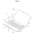
Fig. 1 is a perspective view illustrating a notebook computer of a first exemplary embodiment. -
Fig. 2 is an exploded perspective view illustrating portions of a notebook computer of the first exemplary embodiment -
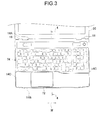
Fig. 3 is a plan view illustrating portions of a notebook computer of the first exemplary embodiment. -
Fig. 4 is a cross-section taken on line 4-4 ofFig. 3 and illustrating portions of a notebook computer of the first exemplary embodiment. -
Fig. 5 is a plan view illustrating a structure inside a case of a notebook computer of the first exemplary embodiment. -
Fig. 6 is an enlarged plan view illustrating portions of a board of a notebook computer of the first exemplary embodiment. -
Fig. 7 is an enlarged perspective view illustrating an HDD and a board of a notebook computer of the first exemplary embodiment. - Detailed explanation follows regarding a first exemplary embodiment, with reference to the drawings.
- As illustrated in
Fig. 1 andFig. 2 , in the first exemplary embodiment a notebook style computer (abbreviated below to "notebook computer") 12 is given as an example of an electronic device. - The
notebook computer 12 of the present exemplary embodiment includes acase 14. Thecase 14 is for example formed in a flat box shape. Thecase 14 is formed in a substantially rectangular shape when viewed in plan view (in the arrow A direction), including afar edge 14A, anear edge 14B, aright edge 14C and aleft edge 14D. - The
case 14 of the present exemplary embodiment has a structure divided in the thickness direction (the arrow T direction) into anupper member 14U and alower member 14L. Theupper member 14U and thelower member 14L are engaged with each other in a superimposed state, using engagement members, (or are fastened together using fastening members, such as screws). Ahousing space 16 is accordingly formed between theupper member 14U and thelower member 14L, as illustrated inFig. 4 . - A
display 20 is rotatably attached at the faredge 14A side of thecase 14 using ahinge 18. As illustrated inFig. 4 , the shape of thecase 14 as viewed from the side face is substantially wedge shaped, with the thickness gradually decreasing continuously or in steps from the faredge 14A side to thenear edge 14B side. - As illustrated in
Fig. 2 , aboard 22, a Hard Disk Drive (HDD) 24, an Optical Disk Drive (ODD) 26 and aradiator device 28 are provided inside the case 14 (between theupper member 14U and thelower member 14L). TheHDD 24, the ODD 26 and theradiator device 28 each serve as examples of internal devices. - The
HDD 24, the ODD 26 and theradiator device 28 are disposed arrayed along one edge of thecase 14. Reference simply to the "array direction" in the following means the direction in which theHDD 24, theODD 26 and theradiator device 28 are arrayed. In the present exemplary embodiment this direction is aligned with the width direction of the case 14 (the arrow W direction). - The
HDD 24 has arotation shaft 24S with length direction oriented in theHDD 24 thickness direction. TheHDD 24 rotates a hard disk about therotation shaft 24S, and performs recording and reading of data to and from the hard disk. - The
ODD 26 similarly has arotation shaft 26S with length direction oriented in theODD 26 thickness direction. TheODD 26 rotates an optical disk that has been inserted through an insertion opening 26H about therotation shaft 26S, and performs recording and reading of data to and from the optical disk. - In particular, in the present exemplary embodiment, the
HDD 24 is disposed at a central position in the array direction (the arrow W direction), with theODD 26 disposed at one longitudinal edge (theright edge 14C inFig. 5 ) side in the array direction (in the arrow W direction). The insertion opening 26H of theODD 26 can thereby be exposed to theright edge 14C side, and an optical disk is accordingly readily inserted therein or taken out therefrom. - The
radiator device 28 includes a radiator fan, enabling heat inside thecase 14 to be externally discharged by externally discharging air inside thecase 14 to outside the case. In the present exemplary embodiment, theradiator device 28 is disposed at the other longitudinal edge (theleft edge 14D inFig. 5 ) side in the array direction (in the arrow W direction). It is accordingly possible to externally discharge air from inside thecase 14 through anexhaust outlet 14G formed in thecase 14 when the radiator fan is being driven. - The
board 22 includes a boardmain body section 30. Acentral processing unit 76, a main storage device and various types of processing circuit are mounted to the boardmain body section 30. - In the present exemplary embodiment, in plan view the board
main body section 30 has a width that is wider than that of the HDD 24 (in effect from the vicinity of theright edge 14C to the vicinity of theleft edge 14D). Note that the boardmain body section 30 is disposed so as to be positioned nearer to thenear edge 14B than theHDD 24, the ODD 26 and theradiator device 28. In other words, the boardmain body section 30 is disposed in a position further away from thefar edge 14A than theHDD 24, theODD 26 and theradiator device 28. - Note that
radiator fins 36 are provided to the boardmain body section 30 at a position on the airflow downstream side from theradiator device 28. Airflow generated by driving theradiator device 28 passes by theradiator fins 36, in a structure capable of achieving effective cooling from theradiator fins 36 of theboard 22 and various peripheral members. - A
battery 38 is attached outside the faredge 14A of thecase 14 and running along the faredge 14A. - The
board 22 includesboard extension portions 32 that extend from the boardmain body section 30 towards thefar edge 14A. The present exemplary embodiment includes, in plan view, afirst extension portion 32A that extends from the left hand side of theODD 26 to between theHDD 24 and theODD 26, and asecond extension portion 32B that is positioned between theHDD 24 and theradiator device 28. A frame shapedportion 40 is also formed by coupling together the leading end of thefirst extension portion 32A and the leading end of thesecond extension portion 32B using aboard coupling portion 34. The frameshaped portion 40 is formed in a shape so as to surround one (or plural) of the internal devices. In the present exemplary embodiment the frameshaped portion 40 is formed in a rectangular shape in plan view so as to be slightly larger than theHDD 24 in plan view. - As illustrated in
Fig. 5 , theboard 22 has a shape and a position so as not to overlap with theHDD 24, theODD 26 or theradiator device 28 in plan view. Moreover, as illustrated inFig. 2 andFig. 4 , the thicknesses of theHDD 24, theODD 26, theradiator device 28 and thebattery 38 are thicker than that of theboard 22. - As illustrated in
Fig. 6 ,HDD connectors first extension portion 32A and theHDD 24 in order to electrically connect theboard 22 and theHDD 24 together directly (not through a cable). TheHDD connector 42C is an example of a board-side connection terminal, and theHDD connector 44C is an example of an internal device-side connection terminal. - As illustrated in
Fig. 7 , aHDD connector 44C of theHDD 24 is detachable from theHDD 24 and is attached to aside edge 24E. TheHDD connector 44C can be attached to theHDD 24 from the arrow B direction. In the attached state of theHDD connector 44C to theHDD 24, the connection portion to theHDD connector 42C faces in theHDD 24 thickness direction (downwards in the illustrated example). Correspondingly, theHDD connector 42C of thefirst extension portion 32A also faces in theboard 22 thickness direction (upwards in the illustrated example) so as to enable connection of theHDD connector 42C to theHDD connector 44C of theHDD 24. - Due to employing the thus configured
HDD connectors HDD 24 and theboard 22 is enabled not by sliding theHDD 24 in the across direction (the arrow W direction) but rather by moving theHDD 24 in the thickness direction (the arrow A direction) into the close vicinity of theboard 22. Space for sliding theHDD 24 in the across direction is accordingly not needed, and a structure is achieved in which it is possible to provide theboard extension portions 32 where such space would have been provided. -
ODD connectors main body section 30 and theODD 26 to electrically connect theboard 22 and theODD 26 together directly (not through a cable). TheODD connector 46C serves as an example of a board-side connection terminal and theODD connector 48C serves as an example of an internal device-side connection terminal. - The
ODD connector 48C of theODD 26 is attached to aside edge 26E so as to face theHDD 24. TheODD connector 48C of theODD 26 is provided at a position displaced from theHDD connector 44C of the HDD in the direction along theside edge 26S (the extension direction of theside edge 26S). - A structure that might, for example, be considered here is a structure in which the
ODD connector 48C is provided facing towards theHDD connector 44C. That is to say, a structure in which theHDD connector 44C and theODD connector 48C are in the same position as each other in the direction along theside edge 26S. - In such cases, due to the
HDD connector 42C and theODD connector 46C of thefirst extension portion 32A also then being in the same position as each other, thefirst extension portion 32A between theHDD connector 42C and theODD connector 46C is made narrower in width by the amounts of theHDD connector 42C and theODD connector 46C. Namely, in order to try to secure certain width in thefirst extension portion 32A between theHDD connector 42C and theODD connector 46C, a width of the sum of theboard extension portion 32, theHDD connector 42C and theODD connector 46C is needed at this portion, resulting in a wider width. - In contrast thereto, in the present exemplary embodiment the
ODD connector 46C is provided in a position displaced from theHDD connector 42C, thereby enabling a shape to be realized that is not excessively wide in width whilst still securing the certain space for theboard extension portions 32. - A
speaker connector 60C employed for connecting to a speaker is provided at the boundary portion of thefirst extension portion 32A and theboard coupling portion 34. AUSB connector 62C employed for connecting to a board for mounting a Universal Serial Bus (USB) port is provided at the boundary portion of thefirst extension portion 32A and theboard coupling portion 34. Apower cable connector 64C that connects to a power cable is also provided at the boundary portion of thefirst extension portion 32A and theboard coupling portion 34. - A
LAN port connector 66C employed for connecting to a LAN port is provided to the boundary portion of thesecond extension portion 32B and theboard coupling portion 34 - A
battery connector 68C employed for connecting to thebattery 38 and adisplay connector 70C for connecting to thedisplay 20 are provided to theboard coupling portion 34. - An HDD
wiring line pattern 42P employed for performing signal communication with theHDD connector 42C and a speakerwiring line pattern 60P employed for transmitting signals to thespeaker connector 60C are provided to thefirst extension portion 32A. A USBwiring line pattern 62P employed for performing signal communication with theUSB connector 62C is also provided as internal wiring to thefirst extension portion 32A. An ODDwiring line pattern 46P employed for performing signal communication with theODD connector 46C is provided to the boardmain body section 30. - A LAN port
wiring line pattern 66P employed for performing signal communication with theLAN port connector 66C is provided to thesecond extension portion 32B. A displaywiring line pattern 70P employed for transmitting signals to thedisplay connector 70C is also provided to thesecond extension portion 32B and theboard coupling portion 34. - A power cable
wiring line pattern 64P that receives power from thepower cable connector 64C and a batterywiring line pattern 68P employed for performing power exchange with thebattery connector 68C are provided to theboard coupling portion 34. - Each of the types of wiring line pattern are provided distributed over the two (plural)
board extension portions 32. In particular, the example described above is a structure that does not have excessive concentration of the wiring line patterns in any one of theboard extension portions 32. Consequently, theboard extension portions 32 can be suppressed from becoming extremely wide or narrow compared to a structure in which wiring line patterns are concentrated in one or the other of theboard extension portions 32. - Note that connectors such as the
speaker connector 60C, theUSB connector 62C, theLAN port connector 66C, thebattery connector 68C and thedisplay connector 70C are examples of board-side connection terminals. - As illustrated in
Fig. 1 to Fig. 4 , anoperation pad 72 is provided on the upper face side of theupper member 14U, and akeyboard 74 is also attached thereto. It is accordingly possible for a user of thenotebook computer 12 to use theoperation pad 72 and thekeyboard 74 to perform input operations. - In particular, in the present exemplary embodiment a portion of the
keyboard 74 and a portion of the boardmain body section 30 overlap with each other when thecase 14 is viewed in plan view. - Explanation follows regarding operation of the
notebook computer 12. - The
notebook computer 12, as illustrated inFig. 2 , has a structure in which theHDD 24, theODD 26 and theradiator device 28 inside thecase 14 do not overlap with theboard 22 in theboard 22 thickness direction. It is accordingly possible to achieve aslimmer case 14 than in a structure in which any of theHDD 24, theODD 26 or theradiator device 28 overlaps with theboard 22. - In particular, the board
main body section 30 is disposed further to thenear edge 14B side than theHDD 24, theODD 26 and theradiator device 28. It is accordingly possible to achieve a slimmer case at thefar edge 14A side than for example in a configuration in which a portion of theboard 22 overlaps with any of theHDD 24, theODD 26 or theradiator device 28 at thefar edge 14A side. - Moreover, in the present exemplary embodiment, the
HDD 24, theODD 26 and theradiator device 28 inside thecase 14 are disposed along thefar edge 14A of thecase 14. The boardmain body section 30 is disposed further towards thenear edge 14B side of thecase 14 than these internal devices. Theboard 22 is thinner than these internal devices, and as illustrated inFig. 4 , it is possible to achieve a shape (a substantially wedge shaped side face) in which the thickness gradually decreases continuously or in steps from thefar edge 14A side towards thenear edge 14B side. - Furthermore, in the present exemplary embodiment, the
HDD 24, theODD 26 and theradiator device 28 that are thicker than theboard 22 are disposed along thefar edge 14A of thecase 14. Accordingly, thecase 14 can be made slimmer than in a structure in which any of these members are disposed at a position near to thenear edge 14B of thecase 14, thereby facilitating the substantially wedge shaped side face of thecase 14 referred to above. - In addition, the
central processing unit 76 is installed to the boardmain body section 30 of thecase 14. TheHDD 24, theODD 26 and theradiator device 28 do not overlap with the boardmain body section 30, thereby enabling sufficient space to be secured for mounting thecentral processing unit 76. - Moreover, in the present exemplary embodiment, the
display 20 is provided at thefar edge 14A of thecase 14. Namely, a user employs thenotebook computer 12 from the comparatively thin side of the case 14 (thenear edge 14B side). This enables a slight slope to be achieved overall for thecase 14 such that thenear edge 14B side of thecase 14 is lower during use of thenotebook computer 12, thereby achieving a structure with excellent input operation through thekeyboard 74 and contact operation to theoperation pad 72. - Structure is such that the
first extension portion 32A and thesecond extension portion 32B extend out from the boardmain body section 30, and thefirst extension portion 32A and thesecond extension portion 32B are also coupled together by theboard coupling portion 34. Wiring cables for connecting theHDD 24 and theODD 26 to the board would for example need to be provided to boards that lack such provision of thefirst extension portion 32A, thesecond extension portion 32B and theboard coupling portion 34. A wiring cable for connecting together thedisplay 20 and the board would be particularly long due to thedisplay 20 being disposed at a position on thefar edge 14A side, namely at a position away from the boardmain body section 30. There is accordingly a concern that a structure having such a wiring cable would lead to an increase in cost of an electronic device. - In contrast thereto, the
board extension portions 32 that are portions of theboard 22 are employed in the present exemplary embodiment as a structure to electrically connect theHDD 24 and theODD 26 to thedisplay 20. A wiring cable is accordingly rendered redundant (or it is possible to shorten a wiring cable), enabling wiring to be simplified. A reduction in manufacturing cost of the electronic device is also possible due to elimination of a process for wiring lay-out. Space inside thecase 14 for laying out such a wiring cable is also not needed, thereby enabling space to be saved. - Moreover, in the present exemplary embodiment, the
HDD 24 is connected by theHDD connectors board 22, so as to be incorporated in a specific position inside thecase 14. Namely, since there is no need to slide theHDD 24 with respect to theboard 22 in the across direction, the space of such a sliding amount is efficiently utilized in the provision of the board extension portions 32 (thefirst extension portion 32A and thesecond extension portion 32B). - The
HDD connector 44C and theODD connector 48C are also provided in positions displaced from each other along theside edge 26S of theODD 26. Excessive widening is accordingly avoided whilst still securing the width needed for theboard extension portion 32, thereby achieving efficient utilization of space. - Note that although in the above there are two of the board extension portions 32 (the
first extension portion 32A and thesecond extension portion 32B) that extend out from the boardmain body section 30, configuration may also be made with only a single board extension portion provided, or with 3 or more board extension portions provided. When two or more of theboard extension portions 32 are provided, it is possible to simplify wiring line patterns while suppressing the width of the respective board extension portions by providing the wiring line patterns to internal devices and external devices distributed between these board extension portions. - Moreover, due to providing each of the types of wiring line pattern distributed across two (plural) of the
board extension portions 32, theboard extension portions 32 can be suppressed from becoming extremely wide in width or extremely narrow in width compared to a structure in which the wiring line patterns are each concentrated on one or the other of theboard extension portions 32. - In particular, in a structure in which the
first extension portion 32A and thesecond extension portion 32B are coupled together by theboard coupling portion 34, if the wiring line patterns are unevenly distributed on one of theboard extension portions 32, then theboard coupling portion 34 also becomes excessively wide at the portion where this wiring line pattern extends to theboard coupling portion 34. Theboard coupling portion 34 can be suppressed from becoming excessively wide by distributing each of the wiring line patterns over two (plural) of theboard extension portions 32. - Moreover, the frame shaped
portion 40 is formed by thefirst extension portion 32A, thesecond extension portion 32B and theboard coupling portion 34. The strength of theboard 22 is accordingly stronger than in structures not formed with such a frame shapedportion 40. Theboard coupling portion 34 of the frame shapedportion 40 is also positioned further to the far side than the internal device (the HDD 24), thereby enabling efficient utilization of space at the far side of the internal device. - An example has been given above in which the
HDD 24 and theODD 26 serve as examples of internal devices. These are often thicker than theboard 22 due to being members that have internal rotation shafts (spindles) with axial directions oriented in theboard 22 thickness direction. Theradiator device 28 is also configured with a rotation shaft with axial direction oriented in theboard 22 thickness direction, and with a fan blade member that rotates about the rotation shaft. Even in structures with members having rotation shafts provided inside thecase 14 it is possible to achieve aslimmer case 14 by, as in the above exemplary embodiment, disposing the internal devices on thefar edge 14A side of thecase 14 and disposing the boardmain body section 30 on thenear edge 14B side. In particular, it is possible to achieve a wedge shape in which the thickness of the side face of thecase 14 gradually decreases from thefar edge 14A side towards thenear edge 14B side. - It is possible to achieve basic operations as a computer when at least the
HDD 24, theODD 26 and theradiator device 28 are provided as internal devices of thenotebook computer 12. In such cases an optical disk is easily inserted into and taken out of theODD 26 by disposing theHDD 24 towards the center along thefar edge 14A of thecase 14 and disposing theODD 26 at an end portion along thefar edge 14A, namely at a side face 14S side. Similarly, exhaust air can be efficiently externally exhausted from thecase 14 by disposing theradiator device 28 at an end portion along thefar edge 14A. Examples other than theHDD 24 of possible auxiliary storage devices that may serve as internal devices include for example a Solid State Drive (SSD). For a radiator device as an internal device, it is also possible to achieve a slimmer electronic device that includes a radiator device in a case by providing the radiator device as one of the internal devices. - The
battery 38 and thedisplay 20 are examples of external devices provided externally to thecase 14. In particular, thebattery 38 is often thicker than theHDD 24 and theODD 26. Consequently, it is possible to achieve a wedge shape in which the side face gradually decreases in thickness from thefar edge 14A side towards thenear edge 14B side by disposing thebattery 38 externally to thecase 14 so as to run along thefar edge 14A of thecase 14. - Note that there is no limitation to the notebook computer described above as the electronic device. Application may, for example, also be made to a desktop computer, to an integrated-display style of computer, to a mobile phone, to an electronic dictionary, or to a mobile audio or video player.
- Explanation has been given above regarding exemplary embodiments of technology disclosed herein, however the technology disclosed herein is not limited by the above, and obviously various other modifications may be implemented within a range not departing from the spirit thereof.
- The technology disclosed herein enables a thinner case to be achieved for an electronic device, and enables wiring inside a case to be simplified.
- All cited documents, patent applications and technical standards mentioned in the present specification are incorporated by reference in the present specification to the same extent as if the individual cited documents, patent applications and technical standards were specifically and individually incorporated by reference in the present specification.
Claims (15)
- An electronic device (12) comprising:a case (14);a board (22) disposed inside the case (14) and including a board main body section (30);a plurality of internal devices (24,26,28) that are disposed inside the case (14) at different positions from the board (22) in plan view of the board (22) and that are thicker than the board (22);a board extension portion (32) that extends out from the board main body section (30) between the plurality of internal devices (24,26,28);a board-side connection terminal (42C,46C,60C,62C,66C,68C,70C) that is provided at the board extension portion (32) and is employed to connect to one of the internal devices (24,26,28) or to an external device (20,38) external to the case (14); andan internal device-side connection terminal (44C,48C) that is provided at one or more of the internal devices (24,26,28) and is connected to the board-side connection terminal (42C,46C,60C,62C,66C,68C,70C).
- The electronic device (12) of claim 1, wherein the plurality of internal devices (24,26,28) are disposed along one edge of the case (14) in plan view.
- The electronic device (12) of claim 2, wherein the board main body section (30) is disposed at a position further away from the one edge of the case (14) than one or more of the internal devices (24,26,28).
- The electronic device (12) of any one of claims 1 to 3, wherein the board-side connection terminal (42C,46C,60C,62C,66C,68C,70C) and the internal device-side connection terminal (44C,48C) are placed in close proximity to each other and connected together by movement in a board thickness direction.
- The electronic device (12) of any one of claims 1 to 4, wherein:at least some of the plurality of internal devices (24,26,28) are disposed adjacent to each other; andthe internal device-side connection terminals (44C,48C) of the adjacent plurality of the internal devices (24,26) are provided on facing sides of the internal devices (24,26) at positions displaced from each other along a length direction of the facing sides.
- The electronic device (12) of any one of claims 1 to 5, wherein a central processing unit (76) is provided at the board main body section (30).
- The electronic device (12) of any one of claims 1 to 6, wherein a display (20) that receives a signal from the board (22) and displays data is attached to one side of the case (14).
- The electronic device (12) of any one of claims 1 to 7, wherein at least one of the plurality of internal devices (24,26) includes a rotation shaft that has an axial direction oriented along a board thickness direction.
- The electronic device (12) of claim 8, wherein the internal devices(24,26) that includes the rotation shaft (24S,26S) among the plurality of internal devices (24,26) is a storage device that rotates a storage medium at the periphery of the rotation shaft (24S,26S).
- The electronic device (12) of any one of claims 1 to 9, wherein at least one of the plurality of internal devices is a radiator device (28) that externally radiates heat from inside the case (14).
- The electronic device (12) of claim 9, wherein:a hard disk drive (24) and an optical disk drive (26) are each provided as the storage device; andthe optical disk drive (26) is disposed at a side face side of the case (14).
- The electronic device (12) of claim 10, wherein the radiator device (28) is disposed at a side face side of the case (14).
- The electronic device (12) of any one of claims 1 to 12, further comprising a plurality of the board extension portions (32).
- The electronic device (12) of claim 13, further comprising a frame shaped portion (40) formed by coupling together leading ends of the plurality of board extension portions (32) with a board coupling portion (34).
- The electronic device (12) of claim 13, further comprising a wiring line pattern (42P,46P,70P) employed to connect together a plurality of the internal devices (24,26,28) or the external device (20,38) distributed across a plurality of the board extension portions (32).
Applications Claiming Priority (1)
| Application Number | Priority Date | Filing Date | Title |
|---|---|---|---|
| JP2012168833A JP5966731B2 (en) | 2012-07-30 | 2012-07-30 | Electronics |
Publications (2)
| Publication Number | Publication Date |
|---|---|
| EP2693294A2 true EP2693294A2 (en) | 2014-02-05 |
| EP2693294A3 EP2693294A3 (en) | 2016-05-25 |
Family
ID=48482917
Family Applications (1)
| Application Number | Title | Priority Date | Filing Date |
|---|---|---|---|
| EP13168107.4A Ceased EP2693294A3 (en) | 2012-07-30 | 2013-05-16 | Electronic device |
Country Status (4)
| Country | Link |
|---|---|
| US (1) | US9019697B2 (en) |
| EP (1) | EP2693294A3 (en) |
| JP (1) | JP5966731B2 (en) |
| CN (1) | CN103576771B (en) |
Families Citing this family (3)
| Publication number | Priority date | Publication date | Assignee | Title |
|---|---|---|---|---|
| US10133314B2 (en) | 2014-05-26 | 2018-11-20 | Apple Inc. | Portable computing system |
| US10228721B2 (en) | 2014-05-26 | 2019-03-12 | Apple Inc. | Portable computing system |
| CN207586791U (en) | 2014-09-30 | 2018-07-06 | 苹果公司 | Portable computing system |
Citations (2)
| Publication number | Priority date | Publication date | Assignee | Title |
|---|---|---|---|---|
| JP2010140510A (en) | 2010-03-11 | 2010-06-24 | Sony Corp | Electronic device |
| EP2461227A2 (en) * | 2010-12-03 | 2012-06-06 | ASUSTeK Computer Inc. | Electronic module and electronic device |
Family Cites Families (13)
| Publication number | Priority date | Publication date | Assignee | Title |
|---|---|---|---|---|
| JPH0455919A (en) * | 1990-06-25 | 1992-02-24 | Toshiba Corp | Personal computer system |
| US5430617A (en) * | 1991-09-30 | 1995-07-04 | Hsu; Winston | Modular electronic packaging for internal I/O modules |
| GB2258326B (en) * | 1991-10-01 | 1995-09-20 | Hsi Kuang Ma | Notebook computer |
| US5448770A (en) | 1993-04-05 | 1995-09-05 | Motorola, Inc. | Temperature-coefficient controlled radio frequency signal detecting circuitry |
| JPH0863260A (en) | 1994-10-19 | 1996-03-08 | Hitachi Ltd | Portable information processing device |
| JP2953423B2 (en) * | 1997-03-26 | 1999-09-27 | 日本電気株式会社 | Portable information processing device |
| JP4151328B2 (en) * | 2002-07-15 | 2008-09-17 | 株式会社日立製作所 | Electronic equipment cooling device |
| JP4534461B2 (en) | 2003-10-23 | 2010-09-01 | ソニー株式会社 | Electronics |
| KR100608830B1 (en) * | 2004-11-09 | 2006-08-09 | 엘지전자 주식회사 | Mobile communication terminal with ground spring finger |
| CN201408379Y (en) * | 2009-03-31 | 2010-02-17 | 深圳市汇科鑫电子技术有限公司 | Ultrathin notebook computer |
| JP4703748B2 (en) * | 2009-07-30 | 2011-06-15 | 株式会社東芝 | Electronics |
| WO2011024319A1 (en) * | 2009-08-31 | 2011-03-03 | 富士通株式会社 | Electronic apparatus |
| CN202067181U (en) * | 2011-04-27 | 2011-12-07 | 联想(北京)有限公司 | Notebook computer and host thereof |
-
2012
- 2012-07-30 JP JP2012168833A patent/JP5966731B2/en not_active Expired - Fee Related
-
2013
- 2013-05-14 US US13/893,765 patent/US9019697B2/en not_active Expired - Fee Related
- 2013-05-16 EP EP13168107.4A patent/EP2693294A3/en not_active Ceased
- 2013-05-31 CN CN201310213640.6A patent/CN103576771B/en not_active Expired - Fee Related
Patent Citations (2)
| Publication number | Priority date | Publication date | Assignee | Title |
|---|---|---|---|---|
| JP2010140510A (en) | 2010-03-11 | 2010-06-24 | Sony Corp | Electronic device |
| EP2461227A2 (en) * | 2010-12-03 | 2012-06-06 | ASUSTeK Computer Inc. | Electronic module and electronic device |
Also Published As
| Publication number | Publication date |
|---|---|
| JP2014026613A (en) | 2014-02-06 |
| JP5966731B2 (en) | 2016-08-10 |
| EP2693294A3 (en) | 2016-05-25 |
| CN103576771B (en) | 2017-05-03 |
| US20140029192A1 (en) | 2014-01-30 |
| CN103576771A (en) | 2014-02-12 |
| US9019697B2 (en) | 2015-04-28 |
Similar Documents
| Publication | Publication Date | Title |
|---|---|---|
| TWI391058B (en) | Motherboard and portable electronic device using the same | |
| JP3178985B2 (en) | Portable electronic devices | |
| US8289692B2 (en) | Blade server for increased processing capacity | |
| US7387539B2 (en) | Reversible universal serial bus connection interface for USB connectors and universal serial bus ports | |
| US11096306B1 (en) | Server | |
| US7467953B2 (en) | Cable connector assembly with improved coupler | |
| US20120287570A1 (en) | Computer enclosure and data storage device bracket of the computer enclosure | |
| CN101431190A (en) | Electric connector | |
| US8599564B2 (en) | Server architecture | |
| US6746255B1 (en) | Serial ATA cable assembly | |
| US20060134940A1 (en) | Electronic apparatus having a connector connecting a disk drive | |
| US6454585B1 (en) | Low profile NIC jumper solution using ZIF connector | |
| US6967837B2 (en) | Computer apparatus assembled wirelessly | |
| EP2693294A2 (en) | Electronic device | |
| US8045324B2 (en) | Cable box and personal computer having same | |
| KR20020057436A (en) | Notebook computer | |
| US8876545B2 (en) | Transmission connector module containable inside a casing of a electronic device in a detachable manner or in a rotable manner | |
| US7641512B2 (en) | Electronic device | |
| US7476106B1 (en) | Rotatable signal socket | |
| CN115734472B (en) | computing devices | |
| US8287304B1 (en) | Flat flexible cable with a data connector and a power connector at one end | |
| CN210033905U (en) | Fan device and fan set | |
| US8498106B2 (en) | Disk drive mounting apparatus | |
| KR200360118Y1 (en) | USB plug unit | |
| CN216750532U (en) | FPC connector of electronic equipment and electronic equipment |
Legal Events
| Date | Code | Title | Description |
|---|---|---|---|
| AK | Designated contracting states |
Kind code of ref document: A2 Designated state(s): AL AT BE BG CH CY CZ DE DK EE ES FI FR GB GR HR HU IE IS IT LI LT LU LV MC MK MT NL NO PL PT RO RS SE SI SK SM TR |
|
| AX | Request for extension of the european patent |
Extension state: BA ME |
|
| PUAI | Public reference made under article 153(3) epc to a published international application that has entered the european phase |
Free format text: ORIGINAL CODE: 0009012 |
|
| PUAL | Search report despatched |
Free format text: ORIGINAL CODE: 0009013 |
|
| AK | Designated contracting states |
Kind code of ref document: A3 Designated state(s): AL AT BE BG CH CY CZ DE DK EE ES FI FR GB GR HR HU IE IS IT LI LT LU LV MC MK MT NL NO PL PT RO RS SE SI SK SM TR |
|
| AX | Request for extension of the european patent |
Extension state: BA ME |
|
| RIC1 | Information provided on ipc code assigned before grant |
Ipc: G06F 1/16 20060101AFI20160419BHEP |
|
| STAA | Information on the status of an ep patent application or granted ep patent |
Free format text: STATUS: REQUEST FOR EXAMINATION WAS MADE |
|
| 17P | Request for examination filed |
Effective date: 20161031 |
|
| RBV | Designated contracting states (corrected) |
Designated state(s): AL AT BE BG CH CY CZ DE DK EE ES FI FR GB GR HR HU IE IS IT LI LT LU LV MC MK MT NL NO PL PT RO RS SE SI SK SM TR |
|
| STAA | Information on the status of an ep patent application or granted ep patent |
Free format text: STATUS: EXAMINATION IS IN PROGRESS |
|
| 17Q | First examination report despatched |
Effective date: 20180327 |
|
| RAP1 | Party data changed (applicant data changed or rights of an application transferred) |
Owner name: FUJITSU CLIENT COMPUTING LIMITED |
|
| STAA | Information on the status of an ep patent application or granted ep patent |
Free format text: STATUS: THE APPLICATION HAS BEEN REFUSED |
|
| 18R | Application refused |
Effective date: 20200418 |