EP2693193A1 - Simulated sunlight irradiation apparatus - Google Patents
Simulated sunlight irradiation apparatus Download PDFInfo
- Publication number
- EP2693193A1 EP2693193A1 EP12764124.9A EP12764124A EP2693193A1 EP 2693193 A1 EP2693193 A1 EP 2693193A1 EP 12764124 A EP12764124 A EP 12764124A EP 2693193 A1 EP2693193 A1 EP 2693193A1
- Authority
- EP
- European Patent Office
- Prior art keywords
- light
- simulated sunlight
- ray
- transmittance
- guide plate
- Prior art date
- Legal status (The legal status is an assumption and is not a legal conclusion. Google has not performed a legal analysis and makes no representation as to the accuracy of the status listed.)
- Withdrawn
Links
Images


Classifications
-
- F—MECHANICAL ENGINEERING; LIGHTING; HEATING; WEAPONS; BLASTING
- F21—LIGHTING
- F21S—NON-PORTABLE LIGHTING DEVICES; SYSTEMS THEREOF; VEHICLE LIGHTING DEVICES SPECIALLY ADAPTED FOR VEHICLE EXTERIORS
- F21S8/00—Lighting devices intended for fixed installation
- F21S8/006—Solar simulators, e.g. for testing photovoltaic panels
-
- G—PHYSICS
- G02—OPTICS
- G02B—OPTICAL ELEMENTS, SYSTEMS OR APPARATUS
- G02B6/00—Light guides; Structural details of arrangements comprising light guides and other optical elements, e.g. couplings
- G02B6/0001—Light guides; Structural details of arrangements comprising light guides and other optical elements, e.g. couplings specially adapted for lighting devices or systems
- G02B6/0011—Light guides; Structural details of arrangements comprising light guides and other optical elements, e.g. couplings specially adapted for lighting devices or systems the light guides being planar or of plate-like form
- G02B6/0013—Means for improving the coupling-in of light from the light source into the light guide
- G02B6/0023—Means for improving the coupling-in of light from the light source into the light guide provided by one optical element, or plurality thereof, placed between the light guide and the light source, or around the light source
- G02B6/0026—Wavelength selective element, sheet or layer, e.g. filter or grating
-
- G—PHYSICS
- G02—OPTICS
- G02B—OPTICAL ELEMENTS, SYSTEMS OR APPARATUS
- G02B6/00—Light guides; Structural details of arrangements comprising light guides and other optical elements, e.g. couplings
- G02B6/0001—Light guides; Structural details of arrangements comprising light guides and other optical elements, e.g. couplings specially adapted for lighting devices or systems
- G02B6/0011—Light guides; Structural details of arrangements comprising light guides and other optical elements, e.g. couplings specially adapted for lighting devices or systems the light guides being planar or of plate-like form
- G02B6/0033—Means for improving the coupling-out of light from the light guide
- G02B6/005—Means for improving the coupling-out of light from the light guide provided by one optical element, or plurality thereof, placed on the light output side of the light guide
-
- G—PHYSICS
- G01—MEASURING; TESTING
- G01N—INVESTIGATING OR ANALYSING MATERIALS BY DETERMINING THEIR CHEMICAL OR PHYSICAL PROPERTIES
- G01N17/00—Investigating resistance of materials to the weather, to corrosion, or to light
- G01N17/002—Test chambers
Definitions
- the present invention relates to a simulated sunlight irradiation apparatus that radiates simulated sunlight.
- Solar batteries have been recognized as important as clean energy sources, and as such, have been in increasing demand. Solar batteries are used in a wide range of fields from power energy sources for large machinery to small-sized power sources for precision electronics. In order for solar batteries to be widely used in a variety of fields, it is necessary that the characteristics, in particular output characteristics, of the solar batteries be accurately measured. Unless the output characteristics are not accurately measured, there will be various inconveniences on the side of solar-battery users. Under such circumstances, there is a particular demand for a technology which can be used for inspections of, measurements of, and experiments on solar batteries and which can irradiate a large area with high-precision simulated sunlight.
- a simulated sunlight irradiation apparatus has recently been under development as an apparatus that can radiate simulated sunlight.
- the simulated sunlight irradiation apparatus is used for measuring the output characteristics of a panel-shaped solar battery by irradiating a receiving surface of the solar battery with artificial light (simulated sunlight) of uniform illuminance.
- simulated sunlight irradiation apparatus is required, in particular, to be high in spectral coincidence.
- spectral coincidence means the proximity of simulated sunlight in spectrum to the reference sunlight.
- the simulated sunlight irradiation apparatus is only provided with light source lamps in the form of dots or lines (dot-like light sources or linear light sources). This problematically makes it extremely difficult to irradiate the whole (or entire) receiving surface, which is in the form of a plane, of a solar battery with simulated sunlight of uniform illuminance.
- Patent Literatures 1 and 2 each disclose a technology for correcting nonuniformity in illuminance of a simulated sunlight irradiation apparatus.
- Patent Literature 1 discloses a simulated sunlight irradiation apparatus (solar simulator) having a halogen lamp and a xenon lamp provided in separate chambers adjacent to each other.
- the simulated sunlight irradiation apparatus has a dedicated optical filter provided in an open section above each of the lamps. This causes the receiving surface of a solar battery to be irradiated with simulated sunlight due to lighting of the lamps below.
- the simulated sunlight irradiation apparatus has a reflective plate in each of the chambers in which the respective lamps are provided. This makes it possible to correct nonuniformity in illuminance among the lamps.
- Patent Literature 2 discloses a simulated sunlight irradiation apparatus (solar simulator) that has a light intensity adjustment member provided for each of those zones into which the receiving surface of a solar battery is imaginarily divided.
- the simulated sunlight irradiation apparatus has three types of light intensity adjustment member having different light-blocking rates.
- the light intensity adjustment members have their light-blocking rates set so that with reference to the illuminance of the darkest zone of the receiving surface of a solar battery, the illuminances of the other zones are made the same as the illuminance of the darkest zone. This makes it possible to make the illuminance of the light sources in one zone of the receiving surface substantially the same as that in another zone of the receiving surface.
- the simulated sunlight irradiation apparatus of Patent Literature 1 is configured such that a lamp that emits xenon light and a lamp that emits halogen light are located in different places. This undesirably causes a degree of mixture of the xenon light and the halogen light to slightly vary, for example, due to a direction in which light from each of the lamps travels. This results in a phenomenon in which simulated sunlight varies in irradiation spectrum from irradiated site to irradiated site. This makes it difficult to make spectral coincidence uniform over the entire irradiated surface, thus making it impossible to configure the simulated sunlight irradiation apparatus to be high in spectral coincidence.
- Patent Literature 2 merely discloses simply providing a light intensity adjustment member in each of those zones into which the receiving surface is imaginarily divided.
- Patent Literature 2 is completely silent about an influence that is exerted on the spectral distribution by providing light intensity adjustment members having different transmittances. That is, in actuality, the simulated sunlight irradiation apparatus of Patent Literature 2 undesirably varies in transmittance among various wavelength bands in each zone. This makes it impossible to radiate simulated sunlight with high spectral coincidence. As such, the simulated sunlight irradiation apparatus of Patent Literature 2 cannot be adapted to raise spectral coincidence, which requires adjustment of transmittance through control of transmittance for each wavelength band.
- the present invention has been made in view of the conventional problems, and it is an object of the present invention to provide a simulated sunlight irradiation apparatus that can radiate simulated sunlight with high spectral coincidence.
- a simulated sunlight irradiation apparatus includes: a first light source which radiates a first ray of light; a second light source which radiates a second ray of light having a spectral distribution that is different from a spectral distribution of the first ray of light; a first optical filter which controls a transmittance of the first ray of light; a second optical filter which controls a transmittance of the second ray of light; a photoselection section which receives the first ray of light whose transmittance has been controlled by the first optical filter and the second ray of light whose transmittance has been controlled by the second optical filter, and which emits simulated sunlight by mixing together a ray of light selected from the first ray of light thus received and a ray of light selected from the second ray of light thus received; a light guide plate which receives the simulated sunlight emitted from the photoselection section; a light extraction section which takes out, to an ir
- the transmittance of the first ray of light is controlled by the first optical filter.
- the transmittance of the first ray of light is controlled by the first optical filter.
- the rays of light whose transmittances have been controlled by the first and second optical filters, respectively, enter the photoselection section.
- emission spectra of the first and second rays of light are adjusted by the first and second optical filters and the photoselection section.
- the transmittance adjustment member located at the side of the irradiation surface of the light guide plate, adjusts a transmittance of light in a portion of a wavelength band of simulated sunlight that is emitted from the irradiation surface of the light guide plate.
- the transmittance adjustment member brings about improvement in spectral coincidence of simulated sunlight. This makes it possible to provide a simulated sunlight irradiation apparatus that can radiate simulated sunlight with high spectral coincidence.
- a simulated sunlight irradiation apparatus is configured to include a transmittance adjustment member which is located closer to the irradiation surface of the light guide plate than the light extraction section is, and which adjusts a transmittance of light in a portion of a wavelength band of simulated sunlight that is emitted from the irradiation surface of the light guide plate.
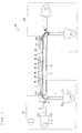
- FIG. 1 is a diagram showing a configuration of a main part of a simulated sunlight irradiation apparatus 100 according to an embodiment of the present invention.
- the simulated sunlight irradiation apparatus 100 includes a light guide plate 10, light introduction sections 20 and 20a, a light extraction section 11, a prism sheet 12, transmittance adjustment members 13a and 13b, and a protective plate 14.
- the simulated sunlight irradiation apparatus 100 emits simulated sunlight (indicated by arrows in the drawing) through an irradiation surface (upper surface) of the light guide plate 10 onto an object to be irradiated, such as a solar battery.
- the simulated sunlight irradiation apparatus 100 is described in detail below. Let it be assumed throughout the following description that the irradiation surface of the light guide plate 10 is an upper side and a (back) surface of the light guide plate 10 opposite the irradiation surface is a lower side.
- the light guide plate 10 is provided between the light introduction sections 20 and 20a placed opposite each other.
- the light guide plate 10 radiates, through an irradiation surface (upper surface) of the light guide plate 10, simulated sunlight with which the light introduction sections 20 and 20a irradiate both side surfaces of the light guide plate 10.
- the light extraction section 11 is provided on a lower surface (back surface) of the light guide plate 10.
- the light extraction section 11 takes out, to the irradiation surface of the light guide plate 10, the simulated sunlight emitted from the light introduction sections 20 and 20a.
- light (simulated sunlight) emitted from the light introduction sections 20 and 20a and having entered the light guide plate 10 propagates through the light guide plate 10.
- light having struck the light extraction section 11 is directed toward the irradiation surface of the light guide plate 10. This makes it possible to uniformly radiate simulated sunlight through a wider irradiation surface.
- the light extraction section 11 can be constituted, for example, by scatterers, which scatter simulated sunlight inside of the light guide plate 10 so that the simulated sunlight can be guided toward the irradiation surface. Further, by changing the pattern of scatterers, nonuniformity in illuminance of the simulated sunlight can be corrected. This makes it possible to radiate uniform simulated sunlight with less nonuniformity in illuminance.
- the prism sheet 12, the transmittance adjustment members 13a and 13b, and the protective plate 14 are placed in this order above the irradiation surface of the light guide plate.
- the prism sheet 12 applies the effect of refraction of light to create a large number of components of irradiation light that is radiated in a direction perpendicular to the irradiation surface of the light guide plate 10. That is, the prism sheet 12 is a member that causes the light extracted by the light extraction section 11 from the light guide plate 10 to be refracted in a direction perpendicular to the irradiation surface of the light guide plate 10.
- the transmittance adjustment members 13a and 13b cause a change in transmittance of light in a portion of a wavelength band of the simulated sunlight that is radiated from the irradiation surface of the light guide plate 10.
- the transmittance adjustment members 13a and 13b will be described in detail later.
- the protective plate 14 covers the irradiation surface of the light guide plate 10 so as to protect the light guide plate 10.
- the light introduction sections 20 and 20a are provided at both side surfaces of the light guide plate 10.
- the light introduction sections 20 and 20a emit the simulated sunlight to to both edges of the light guide plate 10. This makes it possible to emit simulated sunlight of a higher light intensity (illuminance) from the irradiation surface.
- the light introduction section 20a includes optical components identical to those which the light introduction section 20 includes.
- the light introduction section 20 includes: a xenon light source (xenon lamp) 1 (first light source); an elliptic mirror 2 (first light-collecting element; directivity control section); a tapered coupler 3 (tapered light guide member; directivity control section); a halogen light source (halogen lamp) 4 (second light source); an elliptic mirror 5 (second light-collecting element); a tapered coupler 6 (tapered light guide member; directivity control section); a wavelength-mixing filter 7 (photoselection section); optical filters 8 and 9; and reflective plates 15a, 15b, 16a, and 16b (directivity control section).
- the light introduction section 20 generates simulated sunlight by using the wavelength-mixing filter 7 to mix rays of light emitted from the xenon light source 1 and the halogen light source 4, respectively, and irradiates an end face (incident face) of the light guide plate 10 with the simulated sunlight.
- the xenon light source 1 and the halogen light source 4 are light sources provided in the simulated sunlight irradiation apparatus 100.
- the xenon light source 1 and the halogen light source 4 radiate rays of light having spectral distributions that are necessary for generating simulated sunlight.
- the rays of light radiated from the xenon light source 1 and the halogen light source 4 have different spectral distributions from each other.
- the xenon light source 1 mostly radiates a short-wavelength component of light that is necessary for simulated sunlight.
- the halogen light source 4 mostly radiates a long-wavelength component of light that is necessary for simulated sunlight.
- the xenon light source 1 is surrounded by the elliptic mirror 2 (reflecting member) except on a side facing in a direction of emission toward the tapered coupler 3, and the halogen light source 4 is surrounded by the elliptic mirror 5 (reflecting member) except on a side facing in a direction of emission toward the tapered coupler 6.
- This causes rays of light emitted from the xenon light source 1 and the halogen light source 4 but not directed toward the tapered couplers 3 and 6 to be reflected by the elliptic mirrors 2 and 5 and emitted toward the tapered couplers 3 and 6, respectively.
- the elliptic mirrors 2 and 5 collect the rays of light outputted from the respective light sources and cause the rays of light to be emitted.
- the rays of light emitted directly from the xenon light source 1 and the halogen light source 4 and the rays of light reflected by the elliptic mirrors 2 and 5 are emitted toward the tapered couplers 3 and 6, respectively. Therefore, the rays of output light from the xenon light source 1 and the halogen light source 4 are effectively utilized.
- the tapered couplers 3 and 6 are optical elements provided in the light introduction section 20.
- the tapered coupler 3 is provided between the xenon light source 1 and the wavelength-mixing filter 7, and the tapered coupler 6 is provided between the halogen light source 4 and the wavelength-mixing filter 7.
- One end of the tapered coupler 3 is located in proximity to the xenon light source 1, and the other end of the tapered coupler 3 is located in proximity to the wavelength-mixing filter 7.
- One end of the tapered coupler 6 is located in proximity to the halogen light source 4, and the other end of the tapered coupler 6 is located in proximity to the wavelength-mixing filter 7.
- the tapered couplers 3 and 6 are arranged so that a direction of emission of light from the tapered coupler 3 (light from the xenon light source 1) and a direction of emission of light from the tapered coupler 6 (light from the halogen light source 4) form an angle of 90 degrees.
- the light introduction section 20 includes the optical filters 8 and 9 in order to cause simulated sunlight to approximate in emission spectrum to reference sunlight.
- the optical filters 8 and 9 are optical elements that adjust the spectra (control the transmittances) of the rays of light emitted from the xenon light source 1 and the halogen light source 4 (tapered couplers 3 and 6), respectively.
- the optical filters 8 and 9 are generally referred to as "air-mass filters (spectrum adjustment filters)".
- the optical filter 8 is provided in proximity to an emitting face of the tapered coupler 3, which corresponds to the xenon light source 1.
- the optical filter 8 adjusts the spectral distribution of xenon light emitted from the tapered coupler 3.
- the optical filter 9 is provided in proximity to an emitting face of the tapered coupler 6, which corresponds to the halogen light source 4.
- the optical filter 9 adjusts the spectral distribution of halogen light emitted from the tapered coupler 6. This causes the rays of light whose spectra have been adjusted by the optical filters 8 and 9, respectively, to enter the wavelength-mixing filter 7.
- the wavelength-mixing filter 7 has a function of wavelength selection. That is, the wavelength-mixing filter 7 selects (extracts) rays of light that are necessary for simulated sunlight from the rays of light radiated from the xenon light source 1 and the halogen light source 4, and synthesizes simulated sunlight by mixing the rays of light thus selected. Specifically, the wavelength-mixing filter 7 reflects light of a wavelength less than a predetermined wavelength (closer to the short-wavelength side than the predetermined wavelength) and transmits light of a wavelength equal to or greater than the predetermined wavelength (closer to the long-wavelength side than the predetermined wavelength).
- the wavelength-mixing filter 7 has a function of transmitting light on the long-wavelength side that is necessary for simulated sunlight and reflecting light on the short-wavelength side, and synthesizes simulated sunlight by mixing the light on the long-wavelength side and the light on the short-wavelength side.
- the wavelength-mixing filter 7 receives a ray of output light (first rays of light) from the xenon light source 1 and a ray of output light (second ray of light) from the halogen light source 4. Then, the wavelength-mixing filter 7 selects necessary components (spectra) of light from the rays of output light thus received, and synthesizes simulated sunlight by mixing the components of light thus selected.
- the ray of output light from the xenon light source 1 mostly contains a component on the short-wavelength side that is necessary for simulated sunlight; meanwhile, the ray of output light from the halogen light source 4 mostly contains a component on the long-wavelength side that is necessary for simulated sunlight.
- the wavelength-mixing filter 7 has its boundary wavelength set within a range of 600 to 800 nm, the wavelength-mixing filter 7 reflects light of a wavelength less than the boundary wavelength and transmits light of a wavelength equal to or greater than the boundary wavelength. That is, out of the ray of output light from the xenon light source 1, only light of a wavelength less than the boundary wavelength (component of light on the short-wavelength side) is reflected by the wavelength-mixing filter 7. Meanwhile, out of the ray of output light from the halogen light source 4, only light of a wavelength equal to or greater than the boundary wavelength (component of light on the long-wavelength side) is transmitted by the wavelength-mixing filter 7.
- the wavelength-mixing filter 7 has a boundary wavelength of 700 nm between reflection and transmission. That is, the wavelength-mixing filter 7 has ability to reflect short-wavelength light having a wavelength of less than 700 nm and transmit long-wavelength light having a wavelength of 700 nm or greater. This allows only those components of light of wavelengths which are necessary for simulated sunlight to be selected by the wavelength-mixing filter 7. Then, the components of light are combined into simulated sunlight to be emitted.
- the wavelength-mixing filter 7 may be a wavelength-dependent mirror or filter, usable examples of which include a cold mirror, a hot mirror, etc.
- the wavelength-mixing filter 7 generates simulated sunlight by extracting a short-wavelength component of light which is contained in the ray of output light from the xenon light source 1 and which is necessary for the synthesis of simulated sunlight and a long-wavelength component of light which is contained in the ray of output light from the halogen light source 4 and which is necessary for the synthesis of simulated sunlight.
- the wavelength-mixing filter 7 eliminates a long-wavelength component of light from the xenon light source 1 whose spectrum has not been controlled and, similarly, eliminates a short-wavelength component of light from the halogen light source 2 whose spectrum has not been controlled.
- the elliptic mirror 2 is outfitted with the reflecting plates 16a and 16b
- the elliptic mirror 4 is outfitted with the reflecting plates 15a and 15b.
- the reflecting plates 16a and 16b surround an incident face of the tapered coupler 3.
- the reflecting plates 15a and 15b surround an incident face of the tapered coupler 6. This causes rays of light emitted from the xenon light source 1 and the halogen light source 4 toward the tapered couplers 3 and 6 but having not entered the incident faces to be reflected by the reflecting plates 16a and 16b and the reflecting plates 15a and 15b and emitted again toward the tapered couplers 3 and 6, respectively.
- the reflecting plates 16a and 16b and the reflecting plates 15a and 15b collect the rays of light outputted from the respective light sources and cause the rays of light to be emitted.
- the rays of light emitted directly from the xenon light source 1 and the rays of light reflected by the reflecting plates 16a and 16b and the elliptic mirror 2 are emitted toward the tapered coupler 3, and the rays of light emitted directly from the halogen light source 4 and the rays of light reflected by the reflecting plates 15a and 15b and the elliptic mirror 5 are emitted toward the tapered coupler 6. Therefore, the rays of output light from the xenon light source 1 and the halogen light source 4 are effectively utilized.
- the rays of output light from the respective light sources are rays of diffusion light that spread. For this reason, it is preferable that the directivity of the rays of output light from the respective light sources be controlled so that each of the rays of light enters the wavelength-mixing filter 7 at a predetermined angle of incidence.
- the ray of light emitted from the xenon light source 1 has its radiation directivity controlled by the elliptic mirror 2. Furthermore, the ray of light emitted from the xenon light source 1 also has its radiation directivity controlled by the tapered coupler 3. The ray light whose directivity has been controlled passes through the optical filter 8, which adjusts the emission spectrum, and then enters the wavelength-mixing filter 7. Out of the ray of light having entered the wavelength-mixing filter 7, light of a wavelength less than the boundary wavelength (closer to the short-wavelength side than the predetermined wavelength) is reflected by the wavelength-mixing filter 7.
- the ray of light emitted from the halogen light source 4 has its radiation directivity controlled by the elliptic mirror 5. Furthermore, the ray of light emitted from the halogen light source 4 also has its radiation directivity controlled by the tapered coupler 6. The ray light whose directivity has been controlled passes through the optical filter 8, which adjusts the emission spectrum, and then enters the wavelength-mixing filter 7. Out of the ray of light having entered the wavelength-mixing filter 7, light of a wavelength equal to or greater than the boundary wavelength (closer to the long-wavelength side than the predetermined wavelength) is transmitted by the wavelength-mixing filter 7.
- the wavelength-mixing filter 7 mixes together the ray of light emitted from the xenon light source 1 and having its directivity controlled and the ray of light emitted from the halogen light source 4 and having its directivity controlled.
- the xenon light source 1 and the halogen light source 4 are used.
- the irradianace of the xenon light source 1 on the short-wavelength side is comparatively close to the irradiance characteristics of the reference sunlight (as defined by the JIS), and the irradiance of the halogen light source 4 in an infrared region (which ranges mainly from 700 nm to 1100 nm) is close to being substantially constant.
- the xenon light source 1 and the halogen light source 4 are used as light sources from which simulated sunlight is obtained.
- the types of light sources and the combination of the light sources are not to be so limited, but can be optionally selected so that the resulting simulated sunlight is proximate or identical to the reference sunlight.
- rod-shaped light sources and the like instead of using the xenon light source 1 and the halogen light source 4.
- the elliptic mirror 2 is outfitted with the reflecting plates 16a and 16b
- the elliptic mirror 5 is outfitted with the reflecting plates 15a and 15b.
- This causes rays of light having not entered the tapered couplers 3 and 6 to be reflected by the reflecting plates 16a and 16b and the reflecting plates 15a and 15b and then reflected again by the elliptic mirrors 2 and 5 to enter the tapered couplers 3 and 6, respectively.
- Fig. 2 is a diagram showing part of the light introduction section 20 of the simulated sunlight irradiation apparatus 100. That is, Fig. 2 is a top view of the light introduction section 20 as seen from the direction of the arrow Z in Fig. 1 .
- the tapered coupler 6 of the simulated sunlight irradiation apparatus 100 is in a tapered shape (trapezoidal shape) having a pair of opposing faces that become closer to each other toward one end.
- the tapered coupler 3 is also in the same shape. That is, each of the tapered couplers 3 and 6 gradually becomes larger in width (cross-sectional area) from the incident face toward the emitting face of that tapered coupler.
- Such a structure brings about improvement in directivity (angle of radiation) of the rays of light emitted from the xenon light source 1 and the halogen light source 4, as they are repeatedly reflected by the side surfaces of the tapered couplers 3 and 6, respectively.
- use of the tapered couplers 3 and 6 causes all of the rays of light emitted from the xenon light source 1 and the halogen light source 4 to propagate through the tapered couplers 3 and 6, respectively. Further, use of the tapered couplers 3 and 6 causes the rays of light emitted from the xenon light source 1 and the halogen light source 4 to be uniform in traveling direction (directivity), and causes the uniform rays of light to enter the wavelength-mixing filter 7 with low loss.
- the tapered couplers 3 and 6 can be made, for example, of quartz etc.
- each of the optical filters 8 and 9 has a structure in which a plurality of thin films are joined on top of each other. For this reason, a greater shift in the angle of incidence on each of the optical filters 8 and 9 from normal incidence on that optical filter leads to a change in transmittance characteristic. That is, incident of a ray of light to each of the optical filters 8 and 9 with poor directivity leads to generation of simulated sunlight having a spectral distribution that is different from that of the reference sunlight.
- making the rays of light uniform in directivity by using the tapered couplers 3 and 6 makes it possible to generate simulated sunlight that is close in spectral distribution to the reference sunlight.
- the wavelength-mixing filter 7 also has a structure in which a plurality of thin films are joined on top of each other. For this reason, a difference between angles of incidence on the wavelength-mixing filter 7 leads to a change in transmittance characteristic or reflectance characteristic. That is, incident of rays of light to the wavelength-mixing filter 7 with poor directivity leads to generation of simulated sunlight having a spectral distribution that is different from that of the reference sunlight. However, by making the rays of light uniform in directivity by using the tapered couplers 3 and 6, a change in transmission characteristic or reflection characteristic at the wavelength-mixing filter 7 is suppressed. This makes it possible to generate simulated sunlight that is close in spectral distribution to the reference sunlight.
- the directivities of xenon light and halogen light are controlled so that the xenon light enters the optical filter 8 at a predetermined angle of incidence and enters the wavelength-mixing filter 7 at a predetermined angle of incidence and the halogen light enters the optical filter 9 at a predetermined angle of incidence and enters the wavelength-mixing filter 7 at a predetermined angle of incidence. This prevents the xenon light and the halogen light from losing their light intensity by the time they arrive at the wavelength-mixing filter 7.
- the tapered couplers 3 and 6 make the rays of light uniform in directivity, it is possible to generate simulated sunlight that is close in spectral distribution to the reference sunlight. This makes it possible to irradiate an irradiated object with simulated sunlight that is closer in illuminance (light intensity) and emission spectrum to the reference sunlight. It should be noted that with just one of the couplers 3 and 6, it is possible to control the directivity of xenon light or halogen light so that the light can enter the wavelength-mixing filter 7 at a predetermined angle of incidence.
- control of the directivities of rays of light by the tapered couplers 3 and 6 be carried out by causing the rays of light to propagate through the tapered couplers 3 and 6, respectively, in such a manner that the maximum angle of radiation is 30 degrees or smaller.
- This causes each of the rays of light propagating through the tapered couplers 3 and 6 from the incident face to the emitting face to increase in proportion of a component that is emitted with a directivity of 0 degree (i.e., in a direction perpendicular to the emitting face of the tapered coupler 3 or 6).
- the directions of propagation of the rays of light be set so that the elliptic mirrors 2 and 5 collect the rays of light from the xenon light source 1 and the halogen light source 4, respectively, in such a manner that the angle of radiation is 30 degrees or smaller with respect to the normal incidence (0-degree incidence) on the incident end of the tapered coupler 3 or 6.
- the simulated sunlight irradiation apparatus 100 faces a problem in introducing simulated sunlight emitted from the wavelength-mixing filter 7 into the light guide plate 10. Specifically, of the simulated sunlight that enters the light guide plate 10, light whose directivity is poor (whose angle of radiation is close to 30 degrees) increases in component that does not satisfy the total reflection condition for the light to propagate through the light guide plate 10, when after the light has entered the light guide plate 10 there is a shift in propagation angle inside of the light guide plate 10 at which the light propagates through the light guide plate 10. This makes it easy for the light to go out of the light guide plate 10.
- the simulated sunlight irradiation apparatus 100 includes the transmittance adjustment members 13a and 13b.
- the transmittance adjustment members 13a and 13b are located closer to the irradiation surface of the light guide plate 10 than the light extraction section 11 is. Furthermore, the transmittance adjustment members 13a and 13b adjust the transmittance of light in a portion of a wavelength band of the simulated sunlight that is radiated from the irradiation surface, thereby bringing about improvement in spectral coincidence of the simulated sunlight. This makes it possible to radiate simulated sunlight that is high in spectral coincidence.
- the transmittance adjustment members 13a and 13b need only be located closer to the irradiation surface of the light guide plate 10 than the light extraction section 11 is. However, it is preferable that the transmittance adjustment members 13a and 13b be located in the vicinity of either incident face of the light guide plate 10 where there are likely to be a change in transmittance (transmittance characteristic) and therefore a decrease in spectral coincidence. For example, it is preferable that the transmittance adjustment members 13a and 13b be provided above the irradiation surface (emitting face) of the light guide plate 10.
- the transmittance adjustment members 13a and 13b be set to adjust the transmittance of light in a wavelength band of 650 nm to 750 nm where there is likely to be a deviation from the design value.
- the transmittance adjustment members 13a and 13b can each be formed from an optical multi-layer film having ability to reduce the light intensity of light in the wavelength band by 3 to 5% (3% or more and 5% or less). This allows the transmittance adjustment members 13a and 13b to adjust the transmittance to bring about improvement in spectral coincidence.
- the simulated sunlight irradiation apparatus 100 of Fig. 1 includes, for each separate light source, the optical filters 8 and 9 each constituted by a single filter.
- the optical filters 8 and 9 may each be constituted by a plurality of filters.
- Fig. 3 is a diagram showing an example configuration of the optical filter 9 of the simulated sunlight irradiation apparatus 100.
- Such an optical filter 9 as that shown in Fig. 3 which is constituted by a plurality of optical filters (namely three optical filters 9a, 9b, and 9c in Fig 3 ) makes it possible to adjust spectra in finer wavelength bands. This makes it possible to generate simulated sunlight that is more similar in spectral distribution to the reference sunlight.
- Optical filter 9a Optical filter 9b Optical filter 9c Transmittance adjustment wavelength bands 750 nm to 850 nm 900 nm to 1000 nm 700 nm to 1100 nm
- Table 1 shows the transmission characteristics (transmittance adjustment wavelength bands) of the optical filters 9a, 9b, and 9c.
- the transmittance adjustment wavelength band of the optical filter 9a ranges from 750 nm to 850 nm, which is close to the boundary wavelength of 700 nm of the wavelength-mixing filter 7. For this reason, due to the influence of a shift in optical characteristic of the optical filter 9a, a spectral shift may occur in a wider portion of the wavelength band in which the halogen light source 4 is used. In this case, there may be a change in transmittance in the wavelength range of 650 nm to 850 nm and therefore a decrease in spectral coincidence.
- the transmittance adjustment wavelength bands of the transmittance adjustment members 13a and 13b become wider than 650 nm to 750 nm, which makes it necessary to improve the spectral coincidence by adjusting the transmittance in the range of 650 nm to 750 nm.
- Fig. 4 is a graph showing a spectrum of the reference sunlight.
- the reference sunlight exhibits a great change (decrease) in irradiance near 950 nm.
- the optical filter 9b whose transmittance adjustment wavelength band ranges from 900 nm to 1000 nm
- the transmission characteristic varies greatly according to the angle of incidence in the vicinity of the incident face of the light guide plate 10.
- the transmittance adjustment members 13a and 13b adjust at least either a wavelength band including the boundary wavelength (which is here 700 nm) of the wavelength-mixing filter 7 or a wavelength band including a wavelength of around 950 nm where there is a great decrease in irradiance of the reference sunlight. This makes it possible to improve the spectral coincidence in a wavelength band in which there is particularly likely to be a decrease in spectral coincidence.
- the simulated sunlight irradiation apparatus 100 uses the transmittance adjustment members 13a and 13 to control the transmittance of light after emission from the light guide plate 10.
- the directivity of light that is emitted from the light guide plate 10 cannot be completely controlled simply by controlling the transmittance of the light after emission from the light guide plate 10. For this reason, it is difficult to control a spectrum of light after emission.
- the simulated sunlight irradiation apparatus 100 control the directivity of incoming light before it enters the light guide plate 10. That is, the simulated sunlight irradiation apparatus 100 has the tapered coupler 3 and the optical filter 8 provided between the xenon light source 1 and the light guide plate 10, and has the taper coupler 6 and the optical filter 9 provided between the halogen light source 4 and the light guide plate 10. For this reason, a change in directivity of light entering the light guide plate 10 is small even at the incident end of the light guide plate 10 at which there is likely to be a change in directivity of light that is taken out from the light guide plate 10. This makes it possible to control the transmittance by providing the transmittance adjustment members 13a and 13b. Therefore, a spectrum of light after emission can be easily controlled.
- the transmittance adjustment members 13a and 13b which adjust (correct) a shift in transmittance of light in a wavelength band of 650 nm to 750 nm, are provided above the light guide plate 10 near either incident end of the light guide plate 10. This makes it possible to easily adjust the transmittance of light, thus making it possible to control the spectrum even at the incident end of the light guide plate 10. Therefore, a region where the spectral coincidence is high can be extended up to the vicinity of the incident end of the light guide plate 10.
- the simulated sunlight irradiation apparatus 100 be designed so that the angle of incidence on the transmittance adjustment members 13a and 13b ranges from 0 degree (normal incidence) to 30 degrees. This causes the directivity of light that is emitted from the light guide plate 10 to be controlled. Therefore, a spectrum of light after emission can be easily controlled.
- the transmittance adjustment members 13a and 13b are located above the prism sheet 12.
- the transmittance adjustment members 13a and 13b may be located in any other places as long as they are above the irradiation surface of the light guide plate 10.
- the transmittance adjustment members 13a and 13b may be attached to a back surface of the protective plate 14, which is a member that protects the light guide plate 10.
- the prism sheet 12 applies the effect of refraction of light to create a large number of components of irradiation light that is radiated in a direction perpendicular to the irradiation surface of the light guide plate 10, it is possible to highly precisely adjust spectral distributions by using the optical filters 8 and 9.
- Fig. 5 is a diagram showing how the prism sheet 12 and each of the transmittance adjustment members 13a and 13b are provided in the simulated sunlight irradiation apparatus 100 of Fig. 1 . It is preferable that the prism sheet 12 be shaped as shown in Fig. 5 so that each of its prims has a vertex angle of 60 degrees. This causes more of the light that is radiated from the prism sheet 12 to be directed in a direction perpendicular to the irradiation surface of the light guide plate 10, thus causing more of the light incident on the transmittance adjustment members 13a and 13b to be normally incident. This also heightens the controllability of transmittance by the transmittance adjustment members 13a and 13b.
- the transmittance adjustment members 13a and 13b be able to adjust the transmittance near a wavelength of 950 nm in addition to adjusting the transmittance in a wavelength band (wavelength band of 650 nm to 750 nm) around the boundary wavelength of the wavelength-fixing filter 7. Figs.
- FIGS. 6 and 7 are diagrams each showing a configuration of such transmittance adjustment members 13a and 13b. That is, Fig. 6 is a top view showing specific examples of transmittance adjustment members 23a and 23b of the simulated sunlight irradiation apparatus 100 of Fig. 1 . Fig. 7 is a set of cross-sectional views (a) and (b) each showing a configuration of the transmittance adjustment member 23a of Fig. 6 .
- the transmittance adjustment member 23a has regions (transmission characteristic regions for different wavelength bands) 21a and 21b provided in substantially identical positions in the vicinity of the light guide plate 10 so as to adjust the transmittances of rays of light in different wavelength bands.
- the transmittance adjustment member 23b has a single transmission characteristic region 21c configured to adjust the transmittances of rays of light in different wavelength bands.
- the transmittance adjustment member 23a is formed such that the regions 21a and 21b, which have different transmittance adjustment wavelength ranges, are arranged in a staggered manner on a silicone sheet 22 serving as a member on which the regions 21a and 21b are arranged.
- the transmittance adjustment members 23a and 23b be provided on the silicone sheet 22 as shown in Fig. 6 and (a) of Fig. 7 .
- the silicone sheet 22 is low in wavelength dependency of transmission characteristics, and has a viscous surface. This makes it possible to easily place the transmittance adjustment members 23a and 23b without losing the transmission characteristics (transmittance adjustment) of the transmittance adjustment members 23a and 23b, thus making it possible to improve convenience in setting up the transmittance adjustment members 23a and 23b.
- the transmittance adjustment member 23a may be configured to be sandwiched between a pair of silicone sheets as shown in (b) of Fig. 7 .
- the transmittance adjustment member 23a can be protected and given a function of transmittance adjustment (a function of adjusting light intensity).
- the transmittance adjustment members 13a, 13b, 23a, and 23b adjust the transmittance of light in a portion of a wavelength band of the simulated sunlight that is radiated from the irradiation surface of the light guide plate 10. This causes the spectral coincidence of the simulated sunlight to be improved by the transmittance adjustment members 13a, 13b, 23a, and 23b. This makes it possible to provide a simulated sunlight irradiation apparatus 100 that can radiate simulated sunlight with high spectral coincidence. Further, the simulated sunlight irradiation apparatus 100 can irradiate a large-area object to be irradiated, such as a solar battery panel, with uniform simulated sunlight.
- FIG. 8 Another embodiment of the simulated sunlight irradiation apparatus 100 is described below with reference to Figs. 8 through 10 .
- differences from the simulated sunlight irradiation apparatus 100 are mainly explained, and members having the same functions and effects as those of the simulated sunlight irradiation apparatus 100 are given the same reference signs, and as such, are not described below.
- Fig. 8 is a diagram showing a configuration of a main part of a simulated sunlight irradiation apparatus 101.
- Fig. 9 is a diagram showing how a transparent member 24 is provided in the simulated sunlight irradiation apparatus 101 of Fig. 8 .
- the simulated sunlight irradiation apparatus 101 include a reflective plate (reflector) 17 below the lower surface of the light guide plate 10. This makes it possible to further increase the light intensity (illuminance) of simulated sunlight that is radiated from the light guide plate 10.
- the reflective plate 17 is provided at the side of of the light guide plate 10 opposite the irradiation surface.
- the presence of the reflective plate 17 causes light having entered the reflective plate 17 to be reflected toward the irradiation surface of the light guide plate 10. That is, light emitting from the side of the light guide plate 10 opposite the irradiation surface is reflected by the reflective plate 17, and can be returned toward the irradiation surface by the light extraction section 11. This makes it possible to increase the light intensity of the simulated sunlight irradiation apparatus 101.
- a light incident end of the light guide plate 10 differs from other parts of the light guide plate 10 in terms of the ratio between light coming in from the light guide plate 10 and reflected by the reflective plate 17 and light coming out directly from the light guide plate 10.
- the reflective plate 17 is formed from a simple mirror-finished surface of a metal such as Al
- the metal per se exhibits a wavelength-dependent reflectance. Mixing in of a wavelength-dependent reflected light results in a difference between the proportion in which the light reflected by the reflective plate 17 returns to the irradiation surface near the center of the light guide plate 10 and the proportion in which the light reflected by the reflective plate 17 returns to the irradiation surface near either incident end of the light guide plate 10. This may cause a decrease in spectral coincidence at either incident end of the light guide plate 10.
- the Al reflection characteristic changes around a wavelength of 750 nm. That is, since aluminum has a stable reflectance at a short wavelength (ranging from 300 nm to 700 nm), it is unlikely to suffer from a spectral shift; however, it suffers from a spectral shift at a long wavelength (ranging from 700 nm to 850 nm). In other words, the wavelength band in which the transmittance should be adjusted by the transmittance adjustment members 13a and 13b tends to range from 650 nm to 850 nm. Further, aluminum easily becomes lower in reflectance.
- the reflective plate 17 have a surface coated with a protective film.
- the surface of the reflective film 17 is coated with SiO 2 or the like so that wavelength dependency is reduced.
- the reflective plate 17 has a reflectance change of 5% or less in the wavelength band in which the transmittance is adjusted by the transmittance adjustment members 13a and 13b. This makes it possible to reduce the influence (spectral shift) of the change in reflectance by aluminum, thus making it possible to narrow the range of wavelengths in which the transmittance should be adjusted by the transmittance adjustment members 13a and 13b. That is, the control of transmittance by the transmittance adjustment members 13a and 13b can be carried out with finer adjustments. This makes it possible to generate simulated sunlight that is close in emission spectrum to the reference sunlight, without a change in spectral distribution of the simulated sunlight.
- the proportion in which the reflective plate 17 contributes to the amount of irradiation light from the irradiation surface of the light guide plate 10 is approximately 30%, 5% of which is accounted for by a change in reflectance of the reflective plate 17.
- the proportion is approximately 30% because it is assumed that 50% of light having entered the light guide plate 10 emits through the side of the light guide plate 10 opposite the irradiation surface (side of an opposite surface of the light guide plate 10 to the irradiation surface) and arrives at the reflective plate 17, that the light having arrived at the reflective plate 17 is attenuated by approximately 10% due to absorption loss by the reflective plate 17, is further attenuated by approximately 10% by reflection loss when passing through the light guide plate 10 again by being reflected by the reflective plate 17, and is kicked out of the irradiation surface by approximately 15%.
- the simulated sunlight that is radiated from the light guide plate 10 accounts for approximately 1.5% of the influence on a spectrum change. For this reason, even when the spectral coincidence of the simulated sunlight comes close to a maximal performance level of ⁇ 5% (e.g., to Class MS as defined by the JIS), the influence of the reflective plate 17 is acceptable as a vector error. Therefore, it is preferable that the reflective plate 17 has a reflectance change of 5% or less in the wavelength band in which the transmittance is adjusted by the transmittance adjustment members 13a and 13b.
- the transmittance adjustment members 13a and 13b can have their rates of transmittance adjustment smaller than in a case where the reflective plate 17 is a mere metal film (not covered with a protective film). For this reason, it is only necessary to improve the spectral coincidence by forming the transmittance adjustment members 13a and 13b only in a part (near either incident end of the light guide plate 10) where there occurs a decrease in spectral coincidence.
- the simulated sunlight irradiation apparatuses 100 and 101 provision of the transmittance adjustment members 13a, 13b, 23a, and 23b may cause a great decrease in transmittance of simulated sunlight in the places where they are located. Therefore, it is preferable that a transparent member 24 for irradiance adjustment whose transmission characteristic is substantially uniform with respect to a change in wavelength be provided in a place other than the places where the transmittance adjustment members 13a, 13b, 23a, and 23b are provided. That is, the transmittance adjustment members 13a and 13b (23a and 23b) and the transparent member 24, which has a uniform transmission characteristic, are provided above the irradiation surface of the light guide plate 10. This makes it possible to inhibit a decrease in illuminance of simulated sunlight by the transmittance adjustment members, thus making it possible to reduce nonuniformity in illuminance of simulated sunlight.
- Fig. 10 is a diagram showing a component of a main part of a simulated sunlight irradiation apparatus 102.
- the simulated sunlight irradiation apparatus 102 includes a plurality of (eight in Fig. 8 ) light guides 40a to 40h each of which is equivalent to the light guide plate 10 of the simulated sunlight irradiation apparatus 100 or 101.
- the light guides 40a to 40h each have transmittance adjustment members 35a to 35h and 36a to 36h at both ends thereof, respectively.
- the light guides 40a to 40h are each provided with a plurality of (four in Fig. 10 ) light introduction sections 31a through 34a to 31h through 34h, respectively, each of which is equivalent to the light introduction section 20 or 20a in shown in Figs. 1 and 8 .
- the simulated sunlight irradiation apparatus 102 is configured to include identical combinations of the light guides 40a to 40h and the plurality of light introduction sections 31a through 34a to 31h through 34h, respectively. Even so, there may be a variation in irradiation spectrum in the vicinity of the incident ends of the light guides 40a to 40h. For this reason, it is preferable that the transmission characteristics of the transmittance adjustment members 35a to 35h and 36a to 36h, which are to be provided for each separate one of the light guides 40a to 40h, be each independently set.
- the transmission characteristics may be identical to each other. This brings about an increase in spectral coincidence at the incident ends of each of the light guides 40a to 40h. This makes it possible to increase the spectral coincidence even in the case of irradiation of a large area with simulated sunlight.
- the simulated sunlight irradiation apparatus 102 is configured to be effective in highly precisely irradiating a large area with simulated sunlight.
- a simulated sunlight irradiation apparatus includes: a first light source which radiates a first ray of light; a second light source which radiates a second ray of light having a spectral distribution that is different from a spectral distribution of the first ray of light; a first optical filter which controls a transmittance of the first ray of light; a second optical filter which controls a transmittance of the second ray of light; a photoselection section which receives the first ray of light whose transmittance has been controlled by the first optical filter and the second ray of light whose transmittance has been controlled by the second optical filter, and which emits simulated sunlight by mixing together a ray of light selected from the first ray of light thus received and a ray of light selected from the second ray of light thus received; a light guide plate which receives the simulated sunlight emitted from the photoselection section; a light extraction section which takes out, to an irradiation surface of the light
- the transmittance of the first ray of light is controlled by the first optical filter.
- the transmittance of the first ray of light is controlled by the first optical filter.
- the rays of light whose transmittances have been controlled by the first and second optical filters, respectively, enter the photoselection section.
- emission spectra of the first and second rays of light are adjusted by the first and second optical filters and the photoselection section.
- the transmittance adjustment member located at the side of the irradiation surface of the light guide plate, adjusts a transmittance of light in a portion of a wavelength band of simulated sunlight that is emitted from the irradiation surface of the light guide plate.
- the transmittance adjustment member brings about improvement in spectral coincidence of simulated sunlight. This makes it possible to provide a simulated sunlight irradiation apparatus that can radiate simulated sunlight with high spectral coincidence.
- the simulated sunlight irradiation apparatus is preferably configured such that the transmittance adjustment member adjusts the transmittance in at least either a wavelength band including a boundary wavelength that is selected by the photoselection section or a wavelength band including a wavelength of 950 nm.
- the transmittance adjustment member adjusts the transmittance of light in a wavelength band in which there is likely to be a shift in spectral coincidence. This makes it possible to improve the spectral coincidence in a wavelength band in which there is particularly likely to be a decrease in spectral coincidence.
- the simulated sunlight irradiation apparatus is preferably configured such that the transmittance adjustment member is provided in the vicinity of an incident face of the light guide plate on which the simulated sunlight is incident.
- the transmittance adjustment member is located in the vicinity of an incident face of the light guide plate where there are likely to be a change in transmittance and a decrease in spectral coincidence. This makes it possible to prevent a decrease in spectral coincidence at the incident face (introduction end) of the light guide plate.
- the simulated sunlight irradiation apparatus is preferably configured to further include a directivity control section which controls a directivity of at least either the first ray of light or the second ray of light so that the at least either the first ray of light or the second ray of light enters the photoselection section at a predetermined angle of incidence.
- the directivity control section controls a directivity of at least either the first ray of light or the second ray of light.
- This causes a ray of light whose transmittance has been controlled to enter the photoselection section at a predetermined angle of incidence.
- This prevents the first ray of light or the second ray of light from losing its light intensity by the time it arrives at the photoselection section.
- the tapered couplers make the ray of light uniform in directivity, it is possible to generate simulated sunlight that is close in spectral distribution to the reference sunlight. This makes it possible to irradiate an irradiated object with simulated sunlight that is close in illuminance (light intensity) and emission spectrum to the reference sunlight.
- the simulated sunlight irradiation apparatus is preferably configured such that the directivity control section includes (a) a tapered light guide member which causes the at least either the first ray of light or the second ray of light to enter the photoselection section, and which gradually becomes larger in cross-sectional area from an incident face toward an emitting face and (b) a light-collecting element which causes the at least either the first ray of light or the second ray of light to enter the tapered light guide member.
- the light-collecting element causes the at least either the first ray of light or the second ray of light to enter the tapered light guide member. Furthermore, upon entering the tapered light guide member, the at least either the first ray of light or the second ray of light improves in directivity as it is repeatedly reflected by the side surfaces of the the tapered light guide member. This causes a ray of light of uniform directivity (having its angle of radiation controlled) to be emitted from the emitting face of the tapered light guide member. This makes it possible to further improve the directivity of the ray of light.
- the simulated sunlight irradiation apparatus is preferably configured to further include a reflector which is provided at the side of an opposite surface of the light guide plate to the irradiation surface, and which reflects, toward the irradiation surface, simulated sunlight emitted from the opposite surface, wherein the reflector has a reflectance change of 5% or less in the wavelength band in which the transmittance is adjusted by the transmittance adjustment member.
- the reflector reflects, toward the irradiation surface, simulated sunlight emitted from the opposite surface of the light guide plate to the irradiation surface. This allows the simulated sunlight to be emitted from the irradiation surface without being lost. Moreover, the reflector is low in wavelength dependency. Therefore, even in a case where the reflector is provided, simulated sunlight that is high in spectral coincidence can be radiated.
- the reflectance change can be made 5% or less by coating the reflector with SiO 2 , which is low in wavelength dependency.
- the simulated sunlight irradiation apparatus is preferably configured such that the transmittance adjustment member has a plurality of regions which adjust transmittances of rays of light in different wavelength bands.
- the transmittance adjustment member is provided with a plurality of regions which adjust different ranges of wavelengths. This makes it possible to more suitably adjust the transmittance, thus making it possible to further increase the spectral coincidence.
- the simulated sunlight irradiation apparatus is preferably configured such that the transmittance adjustment member is provided on a silicone sheet.
- the transmittance adjustment member is located on the silicone sheet, whose transmission characteristic is low in wavelength dependency. Further, the silicone sheet has a viscous surface. This makes it possible to easily place the transmittance adjustment member without losing the transmission characteristic of the transmittance adjustment member.
- the simulated sunlight irradiation apparatus is preferably configured such that the transmittance adjustment member and a transparent member having a uniform transmission characteristic are provided above the irradiation surface of the light guide plate.
- the transmittance adjustment member is provided above the irradiation surface of the light guide plate, and the transparent member is provided above a place on the irradiation surface where the the transmittance adjustment member is not provided. This makes it possible to inhibit a decrease in illuminance of simulated sunlight by the transmittance adjustment member, thus making it possible to reduce nonuniformity in illuminance of simulated sunlight.
- the simulated sunlight irradiation apparatus is preferably configured such that: the light guide plate includes a plurality of light guides; and the transmittance adjustment member comprises a plurality of transmittance adjustment member provided for each separate one of the light guides.
- the light guide plate includes a plurality of light guides; and the transmittance adjustment member comprises a plurality of transmittance adjustment member provided for each separate one of the light guides.
- the present invention can be used in inspections of, measurements of, and experiments on solar batteries. Further, the present invention can also be used for fading and light-resistance tests on cosmetics, paints, adhesives, and various materials. Furthermore, the present invention can also be used for inspections of and experiments on photocatalysts as well as other various experiments that require natural light.
Landscapes
- Physics & Mathematics (AREA)
- General Physics & Mathematics (AREA)
- Optics & Photonics (AREA)
- Life Sciences & Earth Sciences (AREA)
- Sustainable Development (AREA)
- Engineering & Computer Science (AREA)
- General Engineering & Computer Science (AREA)
- Planar Illumination Modules (AREA)
- Testing Resistance To Weather, Investigating Materials By Mechanical Methods (AREA)
Abstract
Description
- The present invention relates to a simulated sunlight irradiation apparatus that radiates simulated sunlight.
- Solar batteries have been recognized as important as clean energy sources, and as such, have been in increasing demand. Solar batteries are used in a wide range of fields from power energy sources for large machinery to small-sized power sources for precision electronics. In order for solar batteries to be widely used in a variety of fields, it is necessary that the characteristics, in particular output characteristics, of the solar batteries be accurately measured. Unless the output characteristics are not accurately measured, there will be various inconveniences on the side of solar-battery users. Under such circumstances, there is a particular demand for a technology which can be used for inspections of, measurements of, and experiments on solar batteries and which can irradiate a large area with high-precision simulated sunlight.
- Accordingly, a simulated sunlight irradiation apparatus has recently been under development as an apparatus that can radiate simulated sunlight. In general, the simulated sunlight irradiation apparatus is used for measuring the output characteristics of a panel-shaped solar battery by irradiating a receiving surface of the solar battery with artificial light (simulated sunlight) of uniform illuminance.
- A major requirement for simulated sunlight is getting closer in emission spectrum to reference sunlight (as defined by the Japanese Industrial Standards: JIS C8941). In other words, the simulated sunlight irradiation apparatus is required, in particular, to be high in spectral coincidence. The term "spectral coincidence" here means the proximity of simulated sunlight in spectrum to the reference sunlight. However, the simulated sunlight irradiation apparatus is only provided with light source lamps in the form of dots or lines (dot-like light sources or linear light sources). This problematically makes it extremely difficult to irradiate the whole (or entire) receiving surface, which is in the form of a plane, of a solar battery with simulated sunlight of uniform illuminance.
- In order to solve this problem,
Patent Literatures 1 and 2 each disclose a technology for correcting nonuniformity in illuminance of a simulated sunlight irradiation apparatus. -
Patent Literature 1 discloses a simulated sunlight irradiation apparatus (solar simulator) having a halogen lamp and a xenon lamp provided in separate chambers adjacent to each other. Specifically, the simulated sunlight irradiation apparatus has a dedicated optical filter provided in an open section above each of the lamps. This causes the receiving surface of a solar battery to be irradiated with simulated sunlight due to lighting of the lamps below. Furthermore, the simulated sunlight irradiation apparatus has a reflective plate in each of the chambers in which the respective lamps are provided. This makes it possible to correct nonuniformity in illuminance among the lamps. - Meanwhile, Patent Literature 2 discloses a simulated sunlight irradiation apparatus (solar simulator) that has a light intensity adjustment member provided for each of those zones into which the receiving surface of a solar battery is imaginarily divided. Specifically, the simulated sunlight irradiation apparatus has three types of light intensity adjustment member having different light-blocking rates. The light intensity adjustment members have their light-blocking rates set so that with reference to the illuminance of the darkest zone of the receiving surface of a solar battery, the illuminances of the other zones are made the same as the illuminance of the darkest zone. This makes it possible to make the illuminance of the light sources in one zone of the receiving surface substantially the same as that in another zone of the receiving surface.
-
-
Patent Literature 1
Japanese Patent Application Publication, Tokukai, No.2002-048704 (Publication Date: February 15, 2002 - Patent Literature 2
Japanese Patent Application Publication, Tokukai, No.2006-216619 (Publication Date: August 17, 2006 - However, these conventional simulated sunlight irradiation apparatuses are problematically low in spectral coincidence.
- Specifically, the simulated sunlight irradiation apparatus of Patent Literature 1 is configured such that a lamp that emits xenon light and a lamp that emits halogen light are located in different places. This undesirably causes a degree of mixture of the xenon light and the halogen light to slightly vary, for example, due to a direction in which light from each of the lamps travels. This results in a phenomenon in which simulated sunlight varies in irradiation spectrum from irradiated site to irradiated site. This makes it difficult to make spectral coincidence uniform over the entire irradiated surface, thus making it impossible to configure the simulated sunlight irradiation apparatus to be high in spectral coincidence.
- Further, Patent Literature 2 merely discloses simply providing a light intensity adjustment member in each of those zones into which the receiving surface is imaginarily divided. However, Patent Literature 2 is completely silent about an influence that is exerted on the spectral distribution by providing light intensity adjustment members having different transmittances. That is, in actuality, the simulated sunlight irradiation apparatus of Patent Literature 2 undesirably varies in transmittance among various wavelength bands in each zone. This makes it impossible to radiate simulated sunlight with high spectral coincidence. As such, the simulated sunlight irradiation apparatus of Patent Literature 2 cannot be adapted to raise spectral coincidence, which requires adjustment of transmittance through control of transmittance for each wavelength band.
- The present invention has been made in view of the conventional problems, and it is an object of the present invention to provide a simulated sunlight irradiation apparatus that can radiate simulated sunlight with high spectral coincidence.
- In order to solve the foregoing problems, a simulated sunlight irradiation apparatus according to the present invention includes: a first light source which radiates a first ray of light; a second light source which radiates a second ray of light having a spectral distribution that is different from a spectral distribution of the first ray of light; a first optical filter which controls a transmittance of the first ray of light; a second optical filter which controls a transmittance of the second ray of light; a photoselection section which receives the first ray of light whose transmittance has been controlled by the first optical filter and the second ray of light whose transmittance has been controlled by the second optical filter, and which emits simulated sunlight by mixing together a ray of light selected from the first ray of light thus received and a ray of light selected from the second ray of light thus received; a light guide plate which receives the simulated sunlight emitted from the photoselection section; a light extraction section which takes out, to an irradiation surface of the light guide plate, the simulated sunlight received by the light guide plate; and a transmittance adjustment member which is located closer to the irradiation surface of the light guide plate than the light extraction section is, and which adjusts a transmittance of light in a portion of a wavelength band of simulated sunlight that is emitted from the irradiation surface of the light guide plate.
- According to the foregoing invention, when the first ray of light emitted from the first light source enters the first optical filter, the transmittance of the first ray of light is controlled by the first optical filter. Similarly, when the second ray of light emitted from the second light source enters the second optical filter, the transmittance of the first ray of light is controlled by the first optical filter. Then, the rays of light, whose transmittances have been controlled by the first and second optical filters, respectively, enter the photoselection section. In this way, emission spectra of the first and second rays of light are adjusted by the first and second optical filters and the photoselection section. As a result, simulated sunlight that is proximate in emission spectrum to reference sunlight is emitted from the photoselection section. Therefore, simulated sunlight that is high in spectral coincidence enters the light guide plate.
- Furthermore, according to the foregoing invention, the transmittance adjustment member, located at the side of the irradiation surface of the light guide plate, adjusts a transmittance of light in a portion of a wavelength band of simulated sunlight that is emitted from the irradiation surface of the light guide plate. In this way, the transmittance adjustment member brings about improvement in spectral coincidence of simulated sunlight. This makes it possible to provide a simulated sunlight irradiation apparatus that can radiate simulated sunlight with high spectral coincidence.
- Additional objects, features, and strengths of the present invention will be made clear by the description below. Further, the advantages of the present invention will be evident from the following explanation in reference to the drawings.
- As described above, a simulated sunlight irradiation apparatus according to the present invention is configured to include a transmittance adjustment member which is located closer to the irradiation surface of the light guide plate than the light extraction section is, and which adjusts a transmittance of light in a portion of a wavelength band of simulated sunlight that is emitted from the irradiation surface of the light guide plate. This brings about an effect of making it possible to provide a simulated sunlight irradiation apparatus that can radiate simulated sunlight with high spectral coincidence.
-
-
Fig. 1 is a side view showing a configuration of a main part of a simulated sunlight irradiation apparatus according to an embodiment of the present invention. -
Fig. 2 is a diagram showing part of a light introduction section of the simulated sunlight irradiation apparatus ofFig. 1 . -
Fig. 3 is a diagram showing an example configuration of an optical filter of the simulated sunlight irradiation apparatus ofFig. 1 . -
Fig. 4 is a graph showing a spectrum of reference sunlight. -
Fig. 5 is a diagram showing how a prism sheet and a transmittance adjustment member are provided in the simulated sunlight irradiation apparatus ofFig. 1 . -
Fig. 6 is a top view showing specific examples of transmittance adjustment members of the simulated sunlight irradiation apparatus ofFig. 1 . -
Fig. 7 is a set of cross-sectional views (a) and (b) each showing a configuration of a transmittance adjustment member ofFig. 6 . -
Fig. 8 is a diagram showing a configuration of a main part of a simulated sunlight irradiation apparatus according to another embodiment of the present invention. -
Fig. 9 is a diagram showing how a transparent member is provided in the simulated sunlight irradiation apparatus ofFig. 8 . -
Fig. 10 is a diagram showing a configuration of a main part of a simulated sunlight irradiation apparatus according to still another embodiment of the present invention. - An embodiment of the present invention is described below with reference to the drawings.
Fig. 1 is a diagram showing a configuration of a main part of a simulatedsunlight irradiation apparatus 100 according to an embodiment of the present invention. - The simulated
sunlight irradiation apparatus 100 includes alight guide plate 10,light introduction sections light extraction section 11, aprism sheet 12,transmittance adjustment members protective plate 14. The simulatedsunlight irradiation apparatus 100 emits simulated sunlight (indicated by arrows in the drawing) through an irradiation surface (upper surface) of thelight guide plate 10 onto an object to be irradiated, such as a solar battery. The simulatedsunlight irradiation apparatus 100 is described in detail below. Let it be assumed throughout the following description that the irradiation surface of thelight guide plate 10 is an upper side and a (back) surface of thelight guide plate 10 opposite the irradiation surface is a lower side. - The
light guide plate 10 is provided between thelight introduction sections light guide plate 10 radiates, through an irradiation surface (upper surface) of thelight guide plate 10, simulated sunlight with which thelight introduction sections light guide plate 10. - The
light extraction section 11 is provided on a lower surface (back surface) of thelight guide plate 10. Thelight extraction section 11 takes out, to the irradiation surface of thelight guide plate 10, the simulated sunlight emitted from thelight introduction sections light introduction sections light guide plate 10 propagates through thelight guide plate 10. In so doing, light having struck thelight extraction section 11 is directed toward the irradiation surface of thelight guide plate 10. This makes it possible to uniformly radiate simulated sunlight through a wider irradiation surface. It should be noted that thelight extraction section 11 can be constituted, for example, by scatterers, which scatter simulated sunlight inside of thelight guide plate 10 so that the simulated sunlight can be guided toward the irradiation surface. Further, by changing the pattern of scatterers, nonuniformity in illuminance of the simulated sunlight can be corrected. This makes it possible to radiate uniform simulated sunlight with less nonuniformity in illuminance. - The
prism sheet 12, thetransmittance adjustment members protective plate 14 are placed in this order above the irradiation surface of the light guide plate. Theprism sheet 12 applies the effect of refraction of light to create a large number of components of irradiation light that is radiated in a direction perpendicular to the irradiation surface of thelight guide plate 10. That is, theprism sheet 12 is a member that causes the light extracted by thelight extraction section 11 from thelight guide plate 10 to be refracted in a direction perpendicular to the irradiation surface of thelight guide plate 10. Thetransmittance adjustment members light guide plate 10. Thetransmittance adjustment members protective plate 14 covers the irradiation surface of thelight guide plate 10 so as to protect thelight guide plate 10. - The
light introduction sections light guide plate 10. In the simulatedsunlight irradiation apparatus 100, thelight introduction sections light guide plate 10. This makes it possible to emit simulated sunlight of a higher light intensity (illuminance) from the irradiation surface. However, it is possible to provide only thelight guide section 20 at one edge of thelight guide plate 10 instead of providing thelight introduction sections light guide plate 10. That is, the simulatedsunlight irradiation apparatus 100 does not need to include thelight introduction section 20a. It should be noted that thelight introduction section 20a includes optical components identical to those which thelight introduction section 20 includes. - Specifically, the
light introduction section 20 includes: a xenon light source (xenon lamp) 1 (first light source); an elliptic mirror 2 (first light-collecting element; directivity control section); a tapered coupler 3 (tapered light guide member; directivity control section); a halogen light source (halogen lamp) 4 (second light source); an elliptic mirror 5 (second light-collecting element); a tapered coupler 6 (tapered light guide member; directivity control section); a wavelength-mixing filter 7 (photoselection section);optical filters reflective plates - The
light introduction section 20 generates simulated sunlight by using the wavelength-mixingfilter 7 to mix rays of light emitted from thexenon light source 1 and thehalogen light source 4, respectively, and irradiates an end face (incident face) of thelight guide plate 10 with the simulated sunlight. - Specifically, the
xenon light source 1 and thehalogen light source 4 are light sources provided in the simulatedsunlight irradiation apparatus 100. Thexenon light source 1 and thehalogen light source 4 radiate rays of light having spectral distributions that are necessary for generating simulated sunlight. The rays of light radiated from thexenon light source 1 and thehalogen light source 4 have different spectral distributions from each other. Thexenon light source 1 mostly radiates a short-wavelength component of light that is necessary for simulated sunlight. Meanwhile, thehalogen light source 4 mostly radiates a long-wavelength component of light that is necessary for simulated sunlight. - The
xenon light source 1 is surrounded by the elliptic mirror 2 (reflecting member) except on a side facing in a direction of emission toward the taperedcoupler 3, and thehalogen light source 4 is surrounded by the elliptic mirror 5 (reflecting member) except on a side facing in a direction of emission toward the taperedcoupler 6. This causes rays of light emitted from thexenon light source 1 and thehalogen light source 4 but not directed toward the taperedcouplers elliptic mirrors 2 and 5 and emitted toward the taperedcouplers elliptic mirrors 2 and 5 collect the rays of light outputted from the respective light sources and cause the rays of light to be emitted. As a result, the rays of light emitted directly from thexenon light source 1 and thehalogen light source 4 and the rays of light reflected by theelliptic mirrors 2 and 5 are emitted toward the taperedcouplers xenon light source 1 and thehalogen light source 4 are effectively utilized. - The
tapered couplers light introduction section 20. The taperedcoupler 3 is provided between thexenon light source 1 and the wavelength-mixingfilter 7, and the taperedcoupler 6 is provided between thehalogen light source 4 and the wavelength-mixingfilter 7. One end of the taperedcoupler 3 is located in proximity to thexenon light source 1, and the other end of the taperedcoupler 3 is located in proximity to the wavelength-mixingfilter 7. One end of the taperedcoupler 6 is located in proximity to thehalogen light source 4, and the other end of the taperedcoupler 6 is located in proximity to the wavelength-mixingfilter 7. Thetapered couplers - The
light introduction section 20 includes theoptical filters optical filters xenon light source 1 and the halogen light source 4 (taperedcouplers 3 and 6), respectively. Theoptical filters - Specifically, the
optical filter 8 is provided in proximity to an emitting face of the taperedcoupler 3, which corresponds to thexenon light source 1. Theoptical filter 8 adjusts the spectral distribution of xenon light emitted from the taperedcoupler 3. Similarly, theoptical filter 9 is provided in proximity to an emitting face of the taperedcoupler 6, which corresponds to thehalogen light source 4. Theoptical filter 9 adjusts the spectral distribution of halogen light emitted from the taperedcoupler 6. This causes the rays of light whose spectra have been adjusted by theoptical filters filter 7. - The wavelength-mixing
filter 7 has a function of wavelength selection. That is, the wavelength-mixingfilter 7 selects (extracts) rays of light that are necessary for simulated sunlight from the rays of light radiated from thexenon light source 1 and thehalogen light source 4, and synthesizes simulated sunlight by mixing the rays of light thus selected. Specifically, the wavelength-mixingfilter 7 reflects light of a wavelength less than a predetermined wavelength (closer to the short-wavelength side than the predetermined wavelength) and transmits light of a wavelength equal to or greater than the predetermined wavelength (closer to the long-wavelength side than the predetermined wavelength). In other words, the wavelength-mixingfilter 7 has a function of transmitting light on the long-wavelength side that is necessary for simulated sunlight and reflecting light on the short-wavelength side, and synthesizes simulated sunlight by mixing the light on the long-wavelength side and the light on the short-wavelength side. - Specifically, the wavelength-mixing
filter 7 receives a ray of output light (first rays of light) from thexenon light source 1 and a ray of output light (second ray of light) from thehalogen light source 4. Then, the wavelength-mixingfilter 7 selects necessary components (spectra) of light from the rays of output light thus received, and synthesizes simulated sunlight by mixing the components of light thus selected. - More specifically, the ray of output light from the
xenon light source 1 mostly contains a component on the short-wavelength side that is necessary for simulated sunlight; meanwhile, the ray of output light from thehalogen light source 4 mostly contains a component on the long-wavelength side that is necessary for simulated sunlight. Since the wavelength-mixingfilter 7 has its boundary wavelength set within a range of 600 to 800 nm, the wavelength-mixingfilter 7 reflects light of a wavelength less than the boundary wavelength and transmits light of a wavelength equal to or greater than the boundary wavelength. That is, out of the ray of output light from thexenon light source 1, only light of a wavelength less than the boundary wavelength (component of light on the short-wavelength side) is reflected by the wavelength-mixingfilter 7. Meanwhile, out of the ray of output light from thehalogen light source 4, only light of a wavelength equal to or greater than the boundary wavelength (component of light on the long-wavelength side) is transmitted by the wavelength-mixingfilter 7. - For example, let it be assumed that a component of light from the
xenon light source 1 whose wavelength is less than 700 nm is used and a component of light from thehalogen light source 4 whose wavelength is 700 nm or greater is used. In this case, the wavelength-mixingfilter 7 has a boundary wavelength of 700 nm between reflection and transmission. That is, the wavelength-mixingfilter 7 has ability to reflect short-wavelength light having a wavelength of less than 700 nm and transmit long-wavelength light having a wavelength of 700 nm or greater. This allows only those components of light of wavelengths which are necessary for simulated sunlight to be selected by the wavelength-mixingfilter 7. Then, the components of light are combined into simulated sunlight to be emitted. It should be noted that it is possible to set any boundary wavelength between light that the wavelength-mixingfilter 7 reflects and light that the wavelength-mixingfilter 7 transmits. Furthermore, the wavelength-mixingfilter 7 may be a wavelength-dependent mirror or filter, usable examples of which include a cold mirror, a hot mirror, etc. - In this way, the wavelength-mixing
filter 7 generates simulated sunlight by extracting a short-wavelength component of light which is contained in the ray of output light from thexenon light source 1 and which is necessary for the synthesis of simulated sunlight and a long-wavelength component of light which is contained in the ray of output light from thehalogen light source 4 and which is necessary for the synthesis of simulated sunlight. In so doing, the wavelength-mixingfilter 7 eliminates a long-wavelength component of light from thexenon light source 1 whose spectrum has not been controlled and, similarly, eliminates a short-wavelength component of light from the halogen light source 2 whose spectrum has not been controlled. - This makes it possible to cause the simulated sunlight to approximate in emission spectrum to the reference sunlight.
- The elliptic mirror 2 is outfitted with the reflecting
plates elliptic mirror 4 is outfitted with the reflectingplates plates coupler 3. Similarly, the reflectingplates coupler 6. This causes rays of light emitted from thexenon light source 1 and thehalogen light source 4 toward the taperedcouplers plates plates couplers plates plates xenon light source 1 and the rays of light reflected by the reflectingplates coupler 3, and the rays of light emitted directly from thehalogen light source 4 and the rays of light reflected by the reflectingplates elliptic mirror 5 are emitted toward the taperedcoupler 6. Therefore, the rays of output light from thexenon light source 1 and thehalogen light source 4 are effectively utilized. - Since the
xenon light source 1 and thehalogen light source 4 are nondirectional light sources, the rays of output light from the respective light sources are rays of diffusion light that spread. For this reason, it is preferable that the directivity of the rays of output light from the respective light sources be controlled so that each of the rays of light enters the wavelength-mixingfilter 7 at a predetermined angle of incidence. - In the simulated
sunlight irradiation apparatus 100, the ray of light emitted from thexenon light source 1 has its radiation directivity controlled by the elliptic mirror 2. Furthermore, the ray of light emitted from thexenon light source 1 also has its radiation directivity controlled by the taperedcoupler 3. The ray light whose directivity has been controlled passes through theoptical filter 8, which adjusts the emission spectrum, and then enters the wavelength-mixingfilter 7. Out of the ray of light having entered the wavelength-mixingfilter 7, light of a wavelength less than the boundary wavelength (closer to the short-wavelength side than the predetermined wavelength) is reflected by the wavelength-mixingfilter 7. - Meanwhile, the ray of light emitted from the
halogen light source 4 has its radiation directivity controlled by theelliptic mirror 5. Furthermore, the ray of light emitted from thehalogen light source 4 also has its radiation directivity controlled by the taperedcoupler 6. The ray light whose directivity has been controlled passes through theoptical filter 8, which adjusts the emission spectrum, and then enters the wavelength-mixingfilter 7. Out of the ray of light having entered the wavelength-mixingfilter 7, light of a wavelength equal to or greater than the boundary wavelength (closer to the long-wavelength side than the predetermined wavelength) is transmitted by the wavelength-mixingfilter 7. - The wavelength-mixing
filter 7 mixes together the ray of light emitted from thexenon light source 1 and having its directivity controlled and the ray of light emitted from thehalogen light source 4 and having its directivity controlled. In the simulatedsunlight irradiation apparatus 100, thexenon light source 1 and thehalogen light source 4 are used. The irradianace of thexenon light source 1 on the short-wavelength side is comparatively close to the irradiance characteristics of the reference sunlight (as defined by the JIS), and the irradiance of thehalogen light source 4 in an infrared region (which ranges mainly from 700 nm to 1100 nm) is close to being substantially constant. This makes it possible to raise spectral coincidence (to Class MS as defined by the JIS) by using thexenon light source 1 and thehalogen light source 4. Moreover, the rays of light transmitted or reflected by the wavelength-mixingfilter 7 and directed toward thelight guide plate 10 have their spectral coincidence raised by theoptical filters light guide plate 10 receives simulated sunlight with high spectral coincidence. This allows thelight guide plate 10 to radiate light with good spectral coincidence. - It should be noted that in the simulated
sunlight irradiation apparatus 100, thexenon light source 1 and thehalogen light source 4 are used as light sources from which simulated sunlight is obtained. However, the types of light sources and the combination of the light sources are not to be so limited, but can be optionally selected so that the resulting simulated sunlight is proximate or identical to the reference sunlight. For example, it is possible to use rod-shaped light sources and the like instead of using thexenon light source 1 and thehalogen light source 4. - Further, in the simulated
sunlight irradiation apparatus 100, the elliptic mirror 2 is outfitted with the reflectingplates elliptic mirror 5 is outfitted with the reflectingplates couplers plates plates elliptic mirrors 2 and 5 to enter the taperedcouplers xenon light source 1 and thehalogen light source 4, thus making it possible to selectively take out highly directional light. -
Fig. 2 is a diagram showing part of thelight introduction section 20 of the simulatedsunlight irradiation apparatus 100. That is,Fig. 2 is a top view of thelight introduction section 20 as seen from the direction of the arrow Z inFig. 1 . - As shown in
Fig. 2 , the taperedcoupler 6 of the simulatedsunlight irradiation apparatus 100 is in a tapered shape (trapezoidal shape) having a pair of opposing faces that become closer to each other toward one end. The taperedcoupler 3 is also in the same shape. That is, each of the taperedcouplers xenon light source 1 and thehalogen light source 4, as they are repeatedly reflected by the side surfaces of the taperedcouplers couplers couplers couplers couplers - Further, use of the tapered
couplers xenon light source 1 and thehalogen light source 4 to propagate through the taperedcouplers couplers xenon light source 1 and thehalogen light source 4 to be uniform in traveling direction (directivity), and causes the uniform rays of light to enter the wavelength-mixingfilter 7 with low loss. Thetapered couplers - The advantage of making the rays of light uniform in directivity by using the tapered
couplers optical filters optical filters optical filters optical filters couplers - Similarly, the wavelength-mixing
filter 7 also has a structure in which a plurality of thin films are joined on top of each other. For this reason, a difference between angles of incidence on the wavelength-mixingfilter 7 leads to a change in transmittance characteristic or reflectance characteristic. That is, incident of rays of light to the wavelength-mixingfilter 7 with poor directivity leads to generation of simulated sunlight having a spectral distribution that is different from that of the reference sunlight. However, by making the rays of light uniform in directivity by using the taperedcouplers filter 7 is suppressed. This makes it possible to generate simulated sunlight that is close in spectral distribution to the reference sunlight. - Since the simulated
sunlight irradiation apparatus 100 includes the taperedcouplers optical filter 8 at a predetermined angle of incidence and enters the wavelength-mixingfilter 7 at a predetermined angle of incidence and the halogen light enters theoptical filter 9 at a predetermined angle of incidence and enters the wavelength-mixingfilter 7 at a predetermined angle of incidence. This prevents the xenon light and the halogen light from losing their light intensity by the time they arrive at the wavelength-mixingfilter 7. Furthermore, since the taperedcouplers couplers filter 7 at a predetermined angle of incidence. - It is preferable that the control of the directivities of rays of light by the tapered
couplers couplers couplers coupler 3 or 6). Similarly, it is also preferable that the directions of propagation of the rays of light be set so that theelliptic mirrors 2 and 5 collect the rays of light from thexenon light source 1 and thehalogen light source 4, respectively, in such a manner that the angle of radiation is 30 degrees or smaller with respect to the normal incidence (0-degree incidence) on the incident end of the taperedcoupler - The simulated
sunlight irradiation apparatus 100 faces a problem in introducing simulated sunlight emitted from the wavelength-mixingfilter 7 into thelight guide plate 10. Specifically, of the simulated sunlight that enters thelight guide plate 10, light whose directivity is poor (whose angle of radiation is close to 30 degrees) increases in component that does not satisfy the total reflection condition for the light to propagate through thelight guide plate 10, when after the light has entered thelight guide plate 10 there is a shift in propagation angle inside of thelight guide plate 10 at which the light propagates through thelight guide plate 10. This makes it easy for the light to go out of thelight guide plate 10. Further, the closer the angle of radiation is to 30 degrees, the more likely the wavelength-mixingfilter 7 is to reflect or transmit the light at a wavelength of 700 nm at a different transmittance than a design value. This causes the actual transmittance of light of 650 nm to 750 nm at the wavelength-mixingfilter 7 to be higher or lower than the design transmittance. Such a shift in transmittance is a result of an error in manufacture of the film structure of the wavelength-mixingfilter 7. - As a result, simulated sunlight that is radiated from the irradiation surface of the
light guide plate 10 in the vicinity of the incident face of the light guide plate 10 (light that goes out of the light guide plate 10) increases in proportion of light whose transmittance control has deviated from the design. In the simulatedsunlight irradiation apparatus 100, the transmittance of light of a wavelength of 650 nm to 750 nm in particular tends to deviate from the design value. For this reason, even when the spectral coincidence, which indicates proximity in spectrum to the reference sunlight, takes on a satisfactory value in the center of thelight guide plate 10, it is not as good in the vicinity of the incident face (incident end) of thelight guide plate 10. - In order to overcome this problem, the simulated
sunlight irradiation apparatus 100 includes thetransmittance adjustment members transmittance adjustment members light guide plate 10 than thelight extraction section 11 is. Furthermore, thetransmittance adjustment members - The
transmittance adjustment members light guide plate 10 than thelight extraction section 11 is. However, it is preferable that thetransmittance adjustment members light guide plate 10 where there are likely to be a change in transmittance (transmittance characteristic) and therefore a decrease in spectral coincidence. For example, it is preferable that thetransmittance adjustment members light guide plate 10. Furthermore, it is preferable that thetransmittance adjustment members transmittance adjustment members transmittance adjustment members - Incidentally, the simulated
sunlight irradiation apparatus 100 ofFig. 1 includes, for each separate light source, theoptical filters optical filters Fig. 3 is a diagram showing an example configuration of theoptical filter 9 of the simulatedsunlight irradiation apparatus 100. Such anoptical filter 9 as that shown inFig. 3 which is constituted by a plurality of optical filters (namely threeoptical filters Fig 3 ) makes it possible to adjust spectra in finer wavelength bands. This makes it possible to generate simulated sunlight that is more similar in spectral distribution to the reference sunlight.[Table 1] Optical filter 9aOptical filter 9bOptical filter 9cTransmittance adjustment wavelength bands 750 nm to 850 nm 900 nm to 1000 nm 700 nm to 1100 nm - Further, Table 1 shows the transmission characteristics (transmittance adjustment wavelength bands) of the
optical filters optical filter 9a ranges from 750 nm to 850 nm, which is close to the boundary wavelength of 700 nm of the wavelength-mixingfilter 7. For this reason, due to the influence of a shift in optical characteristic of theoptical filter 9a, a spectral shift may occur in a wider portion of the wavelength band in which thehalogen light source 4 is used. In this case, there may be a change in transmittance in the wavelength range of 650 nm to 850 nm and therefore a decrease in spectral coincidence. As a result, the transmittance adjustment wavelength bands of thetransmittance adjustment members - Meanwhile,
Fig. 4 is a graph showing a spectrum of the reference sunlight. The reference sunlight exhibits a great change (decrease) in irradiance near 950 nm. For this reason, as for theoptical filter 9b (whose transmittance adjustment wavelength band ranges from 900 nm to 1000 nm) among theoptical filters light guide plate 10. For this reason, there tends to be a great change in spectral coincidence in a wavelength band of around 950 nm. - Therefore, it is preferable that the
transmittance adjustment members filter 7 or a wavelength band including a wavelength of around 950 nm where there is a great decrease in irradiance of the reference sunlight. This makes it possible to improve the spectral coincidence in a wavelength band in which there is particularly likely to be a decrease in spectral coincidence. - In this way, the simulated
sunlight irradiation apparatus 100 uses thetransmittance adjustment members 13a and 13 to control the transmittance of light after emission from thelight guide plate 10. However, the directivity of light that is emitted from thelight guide plate 10 cannot be completely controlled simply by controlling the transmittance of the light after emission from thelight guide plate 10. For this reason, it is difficult to control a spectrum of light after emission. - Therefore, it is preferable that the simulated
sunlight irradiation apparatus 100 control the directivity of incoming light before it enters thelight guide plate 10. That is, the simulatedsunlight irradiation apparatus 100 has the taperedcoupler 3 and theoptical filter 8 provided between thexenon light source 1 and thelight guide plate 10, and has thetaper coupler 6 and theoptical filter 9 provided between thehalogen light source 4 and thelight guide plate 10. For this reason, a change in directivity of light entering thelight guide plate 10 is small even at the incident end of thelight guide plate 10 at which there is likely to be a change in directivity of light that is taken out from thelight guide plate 10. This makes it possible to control the transmittance by providing thetransmittance adjustment members - Specifically, as mentioned above, light in a wavelength band of 650 nm to 750 nm around the boundary wavelength of the wavelength-mixing
filter 7 is likely to shift in spectrum from the design target. For this reason, thetransmittance adjustment members light guide plate 10 near either incident end of thelight guide plate 10. This makes it possible to easily adjust the transmittance of light, thus making it possible to control the spectrum even at the incident end of thelight guide plate 10. Therefore, a region where the spectral coincidence is high can be extended up to the vicinity of the incident end of thelight guide plate 10. - Further, it is preferable that the simulated
sunlight irradiation apparatus 100 be designed so that the angle of incidence on thetransmittance adjustment members light guide plate 10 to be controlled. Therefore, a spectrum of light after emission can be easily controlled. - It should be noted that in the simulated
sunlight irradiation apparatus 100, thetransmittance adjustment members prism sheet 12. However, thetransmittance adjustment members light guide plate 10. For example, thetransmittance adjustment members protective plate 14, which is a member that protects thelight guide plate 10. - Further, since the
prism sheet 12 applies the effect of refraction of light to create a large number of components of irradiation light that is radiated in a direction perpendicular to the irradiation surface of thelight guide plate 10, it is possible to highly precisely adjust spectral distributions by using theoptical filters - Furthermore,
Fig. 5 is a diagram showing how theprism sheet 12 and each of thetransmittance adjustment members sunlight irradiation apparatus 100 ofFig. 1 . It is preferable that theprism sheet 12 be shaped as shown inFig. 5 so that each of its prims has a vertex angle of 60 degrees. This causes more of the light that is radiated from theprism sheet 12 to be directed in a direction perpendicular to the irradiation surface of thelight guide plate 10, thus causing more of the light incident on thetransmittance adjustment members transmittance adjustment members - Meanwhile, in the case of a distribution in which most components of the light incident on the
light guide plate 10 have incident angle characteristics of around 30 degrees, there is a sudden change in transmittance of the aforementionedoptical filter 9b (Table 1,Fig. 3 ). This increases the angle dependency of the transmittance by thetransmittance adjustment members transmittance adjustment members filter 7.Figs. 6 and 7 are diagrams each showing a configuration of suchtransmittance adjustment members Fig. 6 is a top view showing specific examples oftransmittance adjustment members sunlight irradiation apparatus 100 ofFig. 1 .Fig. 7 is a set of cross-sectional views (a) and (b) each showing a configuration of thetransmittance adjustment member 23a ofFig. 6 . - Specifically, as shown in
Fig. 6 , thetransmittance adjustment member 23a has regions (transmission characteristic regions for different wavelength bands) 21a and 21b provided in substantially identical positions in the vicinity of thelight guide plate 10 so as to adjust the transmittances of rays of light in different wavelength bands. Meanwhile, thetransmittance adjustment member 23b has a single transmissioncharacteristic region 21c configured to adjust the transmittances of rays of light in different wavelength bands. Thetransmittance adjustment member 23a is formed such that theregions silicone sheet 22 serving as a member on which theregions transmittance adjustment members silicone sheet 22 as shown inFig. 6 and (a) ofFig. 7 . Thesilicone sheet 22 is low in wavelength dependency of transmission characteristics, and has a viscous surface. This makes it possible to easily place thetransmittance adjustment members transmittance adjustment members transmittance adjustment members - Further, the
transmittance adjustment member 23a may be configured to be sandwiched between a pair of silicone sheets as shown in (b) ofFig. 7 . By thus structuring the silicone sheets 2 to cover thetransmittance adjustment member 23a, thetransmittance adjustment member 23a can be protected and given a function of transmittance adjustment (a function of adjusting light intensity). - In the simulated
sunlight irradiation apparatus 100, as described above, thetransmittance adjustment members light guide plate 10. This causes the spectral coincidence of the simulated sunlight to be improved by thetransmittance adjustment members sunlight irradiation apparatus 100 that can radiate simulated sunlight with high spectral coincidence. Further, the simulatedsunlight irradiation apparatus 100 can irradiate a large-area object to be irradiated, such as a solar battery panel, with uniform simulated sunlight. - Another embodiment of the simulated
sunlight irradiation apparatus 100 is described below with reference toFigs. 8 through 10 . In the following, differences from the simulatedsunlight irradiation apparatus 100 are mainly explained, and members having the same functions and effects as those of the simulatedsunlight irradiation apparatus 100 are given the same reference signs, and as such, are not described below. -
Fig. 8 is a diagram showing a configuration of a main part of a simulatedsunlight irradiation apparatus 101.Fig. 9 is a diagram showing how atransparent member 24 is provided in the simulatedsunlight irradiation apparatus 101 ofFig. 8 . In addition to the components of the simulatedsunlight irradiation apparatus 100, the simulatedsunlight irradiation apparatus 101 include a reflective plate (reflector) 17 below the lower surface of thelight guide plate 10. This makes it possible to further increase the light intensity (illuminance) of simulated sunlight that is radiated from thelight guide plate 10. - Specifically, in the simulated
sunlight irradiation apparatus 101, thereflective plate 17 is provided at the side of of thelight guide plate 10 opposite the irradiation surface. The presence of thereflective plate 17 causes light having entered thereflective plate 17 to be reflected toward the irradiation surface of thelight guide plate 10. That is, light emitting from the side of thelight guide plate 10 opposite the irradiation surface is reflected by thereflective plate 17, and can be returned toward the irradiation surface by thelight extraction section 11. This makes it possible to increase the light intensity of the simulatedsunlight irradiation apparatus 101. - However, a light incident end of the
light guide plate 10 differs from other parts of thelight guide plate 10 in terms of the ratio between light coming in from thelight guide plate 10 and reflected by thereflective plate 17 and light coming out directly from thelight guide plate 10. This is because, in a case where thereflective plate 17 is formed from a simple mirror-finished surface of a metal such as Al, the metal per se exhibits a wavelength-dependent reflectance. Mixing in of a wavelength-dependent reflected light results in a difference between the proportion in which the light reflected by thereflective plate 17 returns to the irradiation surface near the center of thelight guide plate 10 and the proportion in which the light reflected by thereflective plate 17 returns to the irradiation surface near either incident end of thelight guide plate 10. This may cause a decrease in spectral coincidence at either incident end of thelight guide plate 10. - Specifically, in the case of a
reflective plate 17 made of aluminum, the Al reflection characteristic changes around a wavelength of 750 nm. That is, since aluminum has a stable reflectance at a short wavelength (ranging from 300 nm to 700 nm), it is unlikely to suffer from a spectral shift; however, it suffers from a spectral shift at a long wavelength (ranging from 700 nm to 850 nm). In other words, the wavelength band in which the transmittance should be adjusted by thetransmittance adjustment members - Therefore, it is preferable that the
reflective plate 17 have a surface coated with a protective film. For example, it is preferable that the surface of thereflective film 17 is coated with SiO2 or the like so that wavelength dependency is reduced. For example, it is preferable that thereflective plate 17 has a reflectance change of 5% or less in the wavelength band in which the transmittance is adjusted by thetransmittance adjustment members transmittance adjustment members transmittance adjustment members - Specifically, the proportion in which the
reflective plate 17 contributes to the amount of irradiation light from the irradiation surface of thelight guide plate 10 is approximately 30%, 5% of which is accounted for by a change in reflectance of thereflective plate 17. The proportion is approximately 30% because it is assumed that 50% of light having entered thelight guide plate 10 emits through the side of thelight guide plate 10 opposite the irradiation surface (side of an opposite surface of thelight guide plate 10 to the irradiation surface) and arrives at thereflective plate 17, that the light having arrived at thereflective plate 17 is attenuated by approximately 10% due to absorption loss by thereflective plate 17, is further attenuated by approximately 10% by reflection loss when passing through thelight guide plate 10 again by being reflected by thereflective plate 17, and is kicked out of the irradiation surface by approximately 15%. In this case, the simulated sunlight that is radiated from thelight guide plate 10 accounts for approximately 1.5% of the influence on a spectrum change. For this reason, even when the spectral coincidence of the simulated sunlight comes close to a maximal performance level of ±5% (e.g., to Class MS as defined by the JIS), the influence of thereflective plate 17 is acceptable as a vector error. Therefore, it is preferable that thereflective plate 17 has a reflectance change of 5% or less in the wavelength band in which the transmittance is adjusted by thetransmittance adjustment members - In such a case where the surface of the
reflective film 17 is coated with a protective film made of SiO2 or the like, thetransmittance adjustment members reflective plate 17 is a mere metal film (not covered with a protective film). For this reason, it is only necessary to improve the spectral coincidence by forming thetransmittance adjustment members - It should be noted that the simulated
sunlight irradiation apparatuses transmittance adjustment members transparent member 24 for irradiance adjustment whose transmission characteristic is substantially uniform with respect to a change in wavelength be provided in a place other than the places where thetransmittance adjustment members transmittance adjustment members transparent member 24, which has a uniform transmission characteristic, are provided above the irradiation surface of thelight guide plate 10. This makes it possible to inhibit a decrease in illuminance of simulated sunlight by the transmittance adjustment members, thus making it possible to reduce nonuniformity in illuminance of simulated sunlight. -
Fig. 10 is a diagram showing a component of a main part of a simulatedsunlight irradiation apparatus 102. The simulatedsunlight irradiation apparatus 102 includes a plurality of (eight inFig. 8 ) light guides 40a to 40h each of which is equivalent to thelight guide plate 10 of the simulatedsunlight irradiation apparatus
Furthermore, the light guides 40a to 40h each havetransmittance adjustment members 35a to 35h and 36a to 36h at both ends thereof, respectively. It should be noted that inFig. 10 , the light guides 40a to 40h are each provided with a plurality of (four inFig. 10 )light introduction sections 31a through 34a to 31h through 34h, respectively, each of which is equivalent to thelight introduction section Figs. 1 and8 . - In the case of irradiation of a large area with simulated sunlight, there tends to be a variation in spectral coincidence due to the influence of difference among individual optical elements. In order to counteract this tendency, the simulated
sunlight irradiation apparatus 102 is configured to include identical combinations of the light guides 40a to 40h and the plurality oflight introduction sections 31a through 34a to 31h through 34h, respectively. Even so, there may be a variation in irradiation spectrum in the vicinity of the incident ends of the light guides 40a to 40h. For this reason, it is preferable that the transmission characteristics of thetransmittance adjustment members 35a to 35h and 36a to 36h, which are to be provided for each separate one of the light guides 40a to 40h, be each independently set. Of course, some of the transmission characteristics may be identical to each other. This brings about an increase in spectral coincidence at the incident ends of each of the light guides 40a to 40h. This makes it possible to increase the spectral coincidence even in the case of irradiation of a large area with simulated sunlight. In this way, the simulatedsunlight irradiation apparatus 102 is configured to be effective in highly precisely irradiating a large area with simulated sunlight. - As described above, a simulated sunlight irradiation apparatus according to the present invention includes: a first light source which radiates a first ray of light; a second light source which radiates a second ray of light having a spectral distribution that is different from a spectral distribution of the first ray of light; a first optical filter which controls a transmittance of the first ray of light; a second optical filter which controls a transmittance of the second ray of light; a photoselection section which receives the first ray of light whose transmittance has been controlled by the first optical filter and the second ray of light whose transmittance has been controlled by the second optical filter, and which emits simulated sunlight by mixing together a ray of light selected from the first ray of light thus received and a ray of light selected from the second ray of light thus received; a light guide plate which receives the simulated sunlight emitted from the photoselection section; a light extraction section which takes out, to an irradiation surface of the light guide plate, the simulated sunlight received by the light guide plate; and a transmittance adjustment member which is located closer to the irradiation surface of the light guide plate than the light extraction section is, and which adjusts a transmittance of light in a portion of a wavelength band of simulated sunlight that is emitted from the irradiation surface of the light guide plate.
- According to the foregoing invention, when the first ray of light emitted from the first light source enters the first optical filter, the transmittance of the first ray of light is controlled by the first optical filter. Similarly, when the second ray of light emitted from the second light source enters the second optical filter, the transmittance of the first ray of light is controlled by the first optical filter. Then, the rays of light, whose transmittances have been controlled by the first and second optical filters, respectively, enter the photoselection section. In this way, emission spectra of the first and second rays of light are adjusted by the first and second optical filters and the photoselection section. As a result, simulated sunlight that is proximate in emission spectrum to reference sunlight is emitted from the photoselection section. Therefore, simulated sunlight that is high in spectral coincidence enters the light guide plate.
- Furthermore, according to the foregoing invention, the transmittance adjustment member, located at the side of the irradiation surface of the light guide plate, adjusts a transmittance of light in a portion of a wavelength band of simulated sunlight that is emitted from the irradiation surface of the light guide plate. In this way, the transmittance adjustment member brings about improvement in spectral coincidence of simulated sunlight. This makes it possible to provide a simulated sunlight irradiation apparatus that can radiate simulated sunlight with high spectral coincidence.
- The simulated sunlight irradiation apparatus according to the present invention is preferably configured such that the transmittance adjustment member adjusts the transmittance in at least either a wavelength band including a boundary wavelength that is selected by the photoselection section or a wavelength band including a wavelength of 950 nm.
- According to the foregoing configuration, the transmittance adjustment member adjusts the transmittance of light in a wavelength band in which there is likely to be a shift in spectral coincidence. This makes it possible to improve the spectral coincidence in a wavelength band in which there is particularly likely to be a decrease in spectral coincidence.
- The simulated sunlight irradiation apparatus according to the present invention is preferably configured such that the transmittance adjustment member is provided in the vicinity of an incident face of the light guide plate on which the simulated sunlight is incident.
- According to the present invention, the transmittance adjustment member is located in the vicinity of an incident face of the light guide plate where there are likely to be a change in transmittance and a decrease in spectral coincidence. This makes it possible to prevent a decrease in spectral coincidence at the incident face (introduction end) of the light guide plate.
- The simulated sunlight irradiation apparatus according to the present invention is preferably configured to further include a directivity control section which controls a directivity of at least either the first ray of light or the second ray of light so that the at least either the first ray of light or the second ray of light enters the photoselection section at a predetermined angle of incidence.
- According to the present invention, the directivity control section controls a directivity of at least either the first ray of light or the second ray of light. This causes a ray of light whose transmittance has been controlled to enter the photoselection section at a predetermined angle of incidence. This prevents the first ray of light or the second ray of light from losing its light intensity by the time it arrives at the photoselection section. Furthermore, since the tapered couplers make the ray of light uniform in directivity, it is possible to generate simulated sunlight that is close in spectral distribution to the reference sunlight. This makes it possible to irradiate an irradiated object with simulated sunlight that is close in illuminance (light intensity) and emission spectrum to the reference sunlight.
- The simulated sunlight irradiation apparatus according to the present invention is preferably configured such that the directivity control section includes (a) a tapered light guide member which causes the at least either the first ray of light or the second ray of light to enter the photoselection section, and which gradually becomes larger in cross-sectional area from an incident face toward an emitting face and (b) a light-collecting element which causes the at least either the first ray of light or the second ray of light to enter the tapered light guide member.
- According to the foregoing invention, the light-collecting element causes the at least either the first ray of light or the second ray of light to enter the tapered light guide member. Furthermore, upon entering the tapered light guide member, the at least either the first ray of light or the second ray of light improves in directivity as it is repeatedly reflected by the side surfaces of the the tapered light guide member. This causes a ray of light of uniform directivity (having its angle of radiation controlled) to be emitted from the emitting face of the tapered light guide member. This makes it possible to further improve the directivity of the ray of light.
- The simulated sunlight irradiation apparatus according to the present invention is preferably configured to further include a reflector which is provided at the side of an opposite surface of the light guide plate to the irradiation surface, and which reflects, toward the irradiation surface, simulated sunlight emitted from the opposite surface, wherein the reflector has a reflectance change of 5% or less in the wavelength band in which the transmittance is adjusted by the transmittance adjustment member.
- According to the foregoing invention, the reflector reflects, toward the irradiation surface, simulated sunlight emitted from the opposite surface of the light guide plate to the irradiation surface. This allows the simulated sunlight to be emitted from the irradiation surface without being lost. Moreover, the reflector is low in wavelength dependency. Therefore, even in a case where the reflector is provided, simulated sunlight that is high in spectral coincidence can be radiated.
- It should be noted that the reflectance change can be made 5% or less by coating the reflector with SiO2, which is low in wavelength dependency.
- The simulated sunlight irradiation apparatus according to the present invention is preferably configured such that the transmittance adjustment member has a plurality of regions which adjust transmittances of rays of light in different wavelength bands.
- According to the foregoing invention, the transmittance adjustment member is provided with a plurality of regions which adjust different ranges of wavelengths. This makes it possible to more suitably adjust the transmittance, thus making it possible to further increase the spectral coincidence.
- The simulated sunlight irradiation apparatus according to the present invention is preferably configured such that the transmittance adjustment member is provided on a silicone sheet.
- According to the foregoing invention, the transmittance adjustment member is located on the silicone sheet, whose transmission characteristic is low in wavelength dependency. Further, the silicone sheet has a viscous surface. This makes it possible to easily place the transmittance adjustment member without losing the transmission characteristic of the transmittance adjustment member.
- The simulated sunlight irradiation apparatus according to the present invention is preferably configured such that the transmittance adjustment member and a transparent member having a uniform transmission characteristic are provided above the irradiation surface of the light guide plate.
- According to the foregoing invention, the transmittance adjustment member is provided above the irradiation surface of the light guide plate, and the transparent member is provided above a place on the irradiation surface where the the transmittance adjustment member is not provided. This makes it possible to inhibit a decrease in illuminance of simulated sunlight by the transmittance adjustment member, thus making it possible to reduce nonuniformity in illuminance of simulated sunlight.
- The simulated sunlight irradiation apparatus according to the present invention is preferably configured such that: the light guide plate includes a plurality of light guides; and the transmittance adjustment member comprises a plurality of transmittance adjustment member provided for each separate one of the light guides.
- According to the foregoing invention, the light guide plate includes a plurality of light guides; and the transmittance adjustment member comprises a plurality of transmittance adjustment member provided for each separate one of the light guides. This causes simulated sunlight that is high spectral coincidence to be radiated from each of the light guides. This makes it possible to irradiate a large area with simulated sunlight that is high in spectral coincidence.
- The present invention is not limited to the description of the embodiments above, but may be altered by a skilled person within the scope of the claims. An embodiment based on a proper combination of technical means disclosed in different embodiments is encompassed in the technical scope of the present invention. The embodiments and concrete examples of implementation discussed in the foregoing detailed explanation serve solely to illustrate the technical details of the present invention, which should not be narrowly interpreted within the limits of such embodiments and concrete examples, but rather may be applied in many variations within the spirit of the present invention, provided such variations do not exceed the scope of the patent claims set forth below.
- The present invention can be used in inspections of, measurements of, and experiments on solar batteries. Further, the present invention can also be used for fading and light-resistance tests on cosmetics, paints, adhesives, and various materials. Furthermore, the present invention can also be used for inspections of and experiments on photocatalysts as well as other various experiments that require natural light.
-
- 1
- Xenon light source (first light source)
- 2
- Elliptic mirror (directivity control section, light-collecting element)
- 3
- Tapered coupler (directivity control section)
- 4
- Halogen light source (second light source)
- 5
- Elliptic mirror 5 (directivity control section, light-collecting element)
- 6
- Tapered coupler (directivity control section)
- 7
- Wavelength-mixing filter (photoselection section)
- 8
- Optical filter (first optical filter)
- 9
- Optical filter (second optical filter)
- 9a, 9b, 9c
- Optical filter (second optical filter)
- 10
- Light guide plate
- 11
- Light extraction section
- 12
- Prism sheet
- 13a, 13b
- Transmittance adjustment member
- 15a, 15b
- Reflective plate (directivity control section)
- 16a, 16b
- Reflective plate (directivity control section)
- 17
- Reflective plate (reflector)
- 21a, 21b
- Region (region where transmittance of light is adjusted)
- 21c
- Transmission characteristic region (region where transmittance of light is adjusted)
- 22
- Silicone sheet
- 23a, 23b
- Transmittance adjustment member
- 24
- Transparent member
- 31a to 34a, ... 31h to 34h
- Light introduction section
- 35a to 35h
- Transmittance adjustment member
- 36a to 36h
- Transmittance adjustment member
- 40a to 40h
- Light guide
- 100
- Simulated sunlight irradiation apparatus
- 101
- Simulated sunlight irradiation apparatus
- 102
- Simulated sunlight irradiation apparatus
Claims (11)
- A simulated sunlight irradiation apparatus comprising:a first light source which radiates a first ray of light;a second light source which radiates a second ray of light having a spectral distribution that is different from a spectral distribution of the first ray of light;a first optical filter which controls a transmittance of the first ray of light;a second optical filter which controls a transmittance of the second ray of light;a photoselection section which receives the first ray of light whose transmittance has been controlled by the first optical filter and the second ray of light whose transmittance has been controlled by the second optical filter, and which emits simulated sunlight by mixing together a ray of light selected from the first ray of light thus received and a ray of light selected from the second ray of light thus received;a light guide plate which receives the simulated sunlight emitted from the photoselection section;a light extraction section which takes out, to an irradiation surface of the light guide plate, the simulated sunlight received by the light guide plate; anda transmittance adjustment member which is located closer to the irradiation surface of the light guide plate than the light extraction section is, and which adjusts a transmittance of light in a portion of a wavelength band of simulated sunlight that is emitted from the irradiation surface of the light guide plate.
- The simulated sunlight irradiation apparatus as set forth in claim 1, wherein the transmittance adjustment member adjusts the transmittance in at least either a wavelength band including a boundary wavelength that is selected by the photoselection section or a wavelength band including a wavelength of 950 nm.
- The simulated sunlight irradiation apparatus as set forth in claim 1 or 2, wherein the transmittance adjustment member is provided in the vicinity of an incident face of the light guide plate on which the simulated sunlight is incident.
- The simulated sunlight irradiation apparatus as set forth in any one of claims 1 to 3, further comprising a directivity control section which controls a directivity of at least either the first ray of light or the second ray of light so that the at least either the first ray of light or the second ray of light enters the photoselection section at a predetermined angle of incidence.
- The simulated sunlight irradiation apparatus as set forth in claim 4, wherein the directivity control section includes (a) a tapered light guide member which causes the at least either the first ray of light or the second ray of light to enter the photoselection section, and which gradually becomes larger in cross-sectional area from an incident face toward an emitting face and (b) a light-collecting element which causes the at least either the first ray of light or the second ray of light to enter the tapered light guide member.
- The simulated sunlight irradiation apparatus as set forth in any one of claims 1 to 5, further comprising a reflector which is provided at the side of an opposite surface of the light guide plate to the irradiation surface, and which reflects, toward the irradiation surface, simulated sunlight emitted from the opposite surface, wherein
the reflector has a reflectance change of 5% or less in the wavelength band in which the transmittance is adjusted by the transmittance adjustment member. - The simulated sunlight irradiation apparatus as set forth in claim 6, wherein the reflector has a surface covered with SiO2.
- The simulated sunlight irradiation apparatus as set forth in any one of claims 1 to 7, wherein the transmittance adjustment member has a plurality of regions which adjust transmittances of rays of light in different wavelength bands.
- The simulated sunlight irradiation apparatus as set forth in any one of claims 1 to 7, wherein the transmittance adjustment member is provided on a silicone sheet.
- The simulated sunlight irradiation apparatus as set forth in any one of claims 1 to 9, wherein the transmittance adjustment member and a transparent member having a uniform transmission characteristic are provided above the irradiation surface of the light guide plate.
- The simulated sunlight irradiation apparatus as set forth in any one of claims 1 to 10, wherein:the light guide plate includes a plurality of light guides; andthe transmittance adjustment member comprises a plurality of transmittance adjustment member provided for each separate one of the light guides.
Applications Claiming Priority (2)
| Application Number | Priority Date | Filing Date | Title |
|---|---|---|---|
| JP2011071135A JP5053448B1 (en) | 2011-03-28 | 2011-03-28 | Simulated solar irradiation device |
| PCT/JP2012/053184 WO2012132583A1 (en) | 2011-03-28 | 2012-02-10 | Simulated sunlight irradiation apparatus |
Publications (2)
| Publication Number | Publication Date |
|---|---|
| EP2693193A1 true EP2693193A1 (en) | 2014-02-05 |
| EP2693193A4 EP2693193A4 (en) | 2014-09-03 |
Family
ID=46930347
Family Applications (1)
| Application Number | Title | Priority Date | Filing Date |
|---|---|---|---|
| EP20120764124 Withdrawn EP2693193A4 (en) | 2011-03-28 | 2012-02-10 | Simulated sunlight irradiation apparatus |
Country Status (4)
| Country | Link |
|---|---|
| US (1) | US9022589B2 (en) |
| EP (1) | EP2693193A4 (en) |
| JP (1) | JP5053448B1 (en) |
| WO (1) | WO2012132583A1 (en) |
Families Citing this family (5)
| Publication number | Priority date | Publication date | Assignee | Title |
|---|---|---|---|---|
| EP2920505B1 (en) * | 2012-11-14 | 2020-05-13 | CoeLux S.r.l. | Illumination device synthesizing light from an object at virtually infinite distance |
| WO2014075721A1 (en) | 2012-11-14 | 2014-05-22 | Light In Light S.R.L. | Artificial illumination device for generating natural light |
| WO2015007755A2 (en) * | 2013-07-19 | 2015-01-22 | Koninklijke Philips N.V. | A light emitting device and a method for dimming a light emitting device |
| CN207408286U (en) * | 2017-11-01 | 2018-05-25 | 米亚索乐装备集成(福建)有限公司 | For the reliability test equipment of flexible photovoltaic component |
| WO2020035798A1 (en) * | 2018-08-17 | 2020-02-20 | Avalon St Sàrl | Solar simulator |
Family Cites Families (13)
| Publication number | Priority date | Publication date | Assignee | Title |
|---|---|---|---|---|
| JPH08235903A (en) * | 1995-02-23 | 1996-09-13 | Agency Of Ind Science & Technol | Solar simulator |
| JP3500352B2 (en) | 2000-08-07 | 2004-02-23 | 日清紡績株式会社 | Solar simulator |
| JP4087239B2 (en) * | 2002-12-12 | 2008-05-21 | 日東電工株式会社 | Glass filter for preventing glass breakage and plasma display device |
| JP2007158379A (en) * | 2004-12-06 | 2007-06-21 | Ricoh Co Ltd | Illumination device, image sensor unit, image reading device, and image forming device |
| US20060152777A1 (en) | 2004-12-06 | 2006-07-13 | Takeshi Iwasaki | Image processing method and apparatus capable of effectively reading an image using a light diffuser |
| JP5236858B2 (en) | 2005-02-01 | 2013-07-17 | 日清紡ホールディングス株式会社 | Measuring method of output characteristics of solar cell. |
| JP2007334325A (en) * | 2006-05-18 | 2007-12-27 | Fujifilm Corp | Near-infrared absorbing filter and manufacturing method thereof |
| WO2009093452A1 (en) | 2008-01-23 | 2009-07-30 | Panasonic Corporation | Wavelength splitting device, plane-type lighting device using same, and liquid crystal display device using same |
| JP2010277712A (en) | 2009-05-26 | 2010-12-09 | Sony Corp | Illumination device and display device |
| JP4570680B1 (en) | 2009-06-12 | 2010-10-27 | シャープ株式会社 | Light irradiation device and inspection device |
| IT1399180B1 (en) | 2009-06-12 | 2013-04-11 | Sharp Kk | SOLAR SIMULATOR |
| JP2011033871A (en) * | 2009-08-03 | 2011-02-17 | Nippon Shinku Kogaku Kk | Light source apparatus capable of adjusting spectral radiation distribution |
| JP4723038B1 (en) | 2010-03-30 | 2011-07-13 | シャープ株式会社 | Simulated solar irradiation device |
-
2011
- 2011-03-28 JP JP2011071135A patent/JP5053448B1/en not_active Expired - Fee Related
-
2012
- 2012-02-10 WO PCT/JP2012/053184 patent/WO2012132583A1/en not_active Ceased
- 2012-02-10 EP EP20120764124 patent/EP2693193A4/en not_active Withdrawn
- 2012-02-10 US US13/985,439 patent/US9022589B2/en not_active Expired - Fee Related
Also Published As
| Publication number | Publication date |
|---|---|
| EP2693193A4 (en) | 2014-09-03 |
| JP5053448B1 (en) | 2012-10-17 |
| US9022589B2 (en) | 2015-05-05 |
| JP2012202976A (en) | 2012-10-22 |
| WO2012132583A1 (en) | 2012-10-04 |
| US20140009901A1 (en) | 2014-01-09 |
Similar Documents
| Publication | Publication Date | Title |
|---|---|---|
| JP5826597B2 (en) | Simulated solar irradiation device | |
| JP4570680B1 (en) | Light irradiation device and inspection device | |
| EP2530369A1 (en) | Simulated solar light irradiation device and simulated solar light irradiation method | |
| US9022589B2 (en) | Simulated sunlight irradiation apparatus | |
| EP3143344B1 (en) | Illumination device simulating the natural illumination and including an infrared light source | |
| US20120275132A1 (en) | Pseudo-Sunlight Irradiating Apparatus | |
| US11248773B2 (en) | Light source system and lighting apparatus | |
| EP2444721A1 (en) | Light source apparatus and simulated solar light irradiation apparatus provided with same | |
| JP5583468B2 (en) | Simulated solar irradiation device | |
| JP5214792B2 (en) | Simulated solar irradiation device | |
| US9046234B2 (en) | Simulated solar irradiation device and spectral adjustment method thereof | |
| JP5274528B2 (en) | Pseudo-sunlight irradiation device and solar panel inspection device | |
| EP2589857A1 (en) | Light source apparatus and pseudo-sunlight irradiating apparatus provided with same | |
| JP2012084672A (en) | Pseudo sunlight irradiation device and solar cell panel inspection apparatus | |
| JP5049375B2 (en) | Simulated solar irradiation device | |
| US9115859B2 (en) | Artificial sunlight radiation device | |
| JP5868660B2 (en) | Simulated solar irradiation device | |
| JP2013251154A (en) | Pseudo-sunlight irradiation device | |
| WO2013038769A1 (en) | Artificial-sunlight projection device |
Legal Events
| Date | Code | Title | Description |
|---|---|---|---|
| PUAI | Public reference made under article 153(3) epc to a published international application that has entered the european phase |
Free format text: ORIGINAL CODE: 0009012 |
|
| 17P | Request for examination filed |
Effective date: 20130814 |
|
| AK | Designated contracting states |
Kind code of ref document: A1 Designated state(s): AL AT BE BG CH CY CZ DE DK EE ES FI FR GB GR HR HU IE IS IT LI LT LU LV MC MK MT NL NO PL PT RO RS SE SI SK SM TR |
|
| DAX | Request for extension of the european patent (deleted) | ||
| A4 | Supplementary search report drawn up and despatched |
Effective date: 20140731 |
|
| RIC1 | Information provided on ipc code assigned before grant |
Ipc: G01N 17/00 20060101AFI20140725BHEP |
|
| 17Q | First examination report despatched |
Effective date: 20150309 |
|
| STAA | Information on the status of an ep patent application or granted ep patent |
Free format text: STATUS: THE APPLICATION IS DEEMED TO BE WITHDRAWN |
|
| 18D | Application deemed to be withdrawn |
Effective date: 20150721 |