EP2692690A1 - Method for controlling mixing in of metal in apparatus for manufacturing synthetic gas - Google Patents
Method for controlling mixing in of metal in apparatus for manufacturing synthetic gas Download PDFInfo
- Publication number
- EP2692690A1 EP2692690A1 EP12765528.0A EP12765528A EP2692690A1 EP 2692690 A1 EP2692690 A1 EP 2692690A1 EP 12765528 A EP12765528 A EP 12765528A EP 2692690 A1 EP2692690 A1 EP 2692690A1
- Authority
- EP
- European Patent Office
- Prior art keywords
- synthesis gas
- carbon dioxide
- gas production
- fischer
- reforming
- Prior art date
- Legal status (The legal status is an assumption and is not a legal conclusion. Google has not performed a legal analysis and makes no representation as to the accuracy of the status listed.)
- Withdrawn
Links
Images

Classifications
-
- C—CHEMISTRY; METALLURGY
- C10—PETROLEUM, GAS OR COKE INDUSTRIES; TECHNICAL GASES CONTAINING CARBON MONOXIDE; FUELS; LUBRICANTS; PEAT
- C10G—CRACKING HYDROCARBON OILS; PRODUCTION OF LIQUID HYDROCARBON MIXTURES, e.g. BY DESTRUCTIVE HYDROGENATION, OLIGOMERISATION, POLYMERISATION; RECOVERY OF HYDROCARBON OILS FROM OIL-SHALE, OIL-SAND, OR GASES; REFINING MIXTURES MAINLY CONSISTING OF HYDROCARBONS; REFORMING OF NAPHTHA; MINERAL WAXES
- C10G2/00—Production of liquid hydrocarbon mixtures of undefined composition from oxides of carbon
- C10G2/30—Production of liquid hydrocarbon mixtures of undefined composition from oxides of carbon from carbon monoxide with hydrogen
-
- C—CHEMISTRY; METALLURGY
- C01—INORGANIC CHEMISTRY
- C01B—NON-METALLIC ELEMENTS; COMPOUNDS THEREOF; METALLOIDS OR COMPOUNDS THEREOF NOT COVERED BY SUBCLASS C01C
- C01B3/00—Hydrogen; Gaseous mixtures containing hydrogen; Separation of hydrogen from mixtures containing it; Purification of hydrogen; Reversible storage of hydrogen
- C01B3/02—Production of hydrogen; Production of gaseous mixtures containing hydrogen
- C01B3/32—Production of hydrogen; Production of gaseous mixtures containing hydrogen by reaction of gaseous or liquid organic compounds with gasifying agents, e.g. water, carbon dioxide or air
- C01B3/34—Production of hydrogen; Production of gaseous mixtures containing hydrogen by reaction of gaseous or liquid organic compounds with gasifying agents, e.g. water, carbon dioxide or air by reaction of hydrocarbons with gasifying agents
- C01B3/38—Production of hydrogen; Production of gaseous mixtures containing hydrogen by reaction of gaseous or liquid organic compounds with gasifying agents, e.g. water, carbon dioxide or air by reaction of hydrocarbons with gasifying agents using catalysts
-
- C—CHEMISTRY; METALLURGY
- C01—INORGANIC CHEMISTRY
- C01B—NON-METALLIC ELEMENTS; COMPOUNDS THEREOF; METALLOIDS OR COMPOUNDS THEREOF NOT COVERED BY SUBCLASS C01C
- C01B3/00—Hydrogen; Gaseous mixtures containing hydrogen; Separation of hydrogen from mixtures containing it; Purification of hydrogen; Reversible storage of hydrogen
- C01B3/02—Production of hydrogen; Production of gaseous mixtures containing hydrogen
- C01B3/32—Production of hydrogen; Production of gaseous mixtures containing hydrogen by reaction of gaseous or liquid organic compounds with gasifying agents, e.g. water, carbon dioxide or air
- C01B3/34—Production of hydrogen; Production of gaseous mixtures containing hydrogen by reaction of gaseous or liquid organic compounds with gasifying agents, e.g. water, carbon dioxide or air by reaction of hydrocarbons with gasifying agents
- C01B3/38—Production of hydrogen; Production of gaseous mixtures containing hydrogen by reaction of gaseous or liquid organic compounds with gasifying agents, e.g. water, carbon dioxide or air by reaction of hydrocarbons with gasifying agents using catalysts
- C01B3/384—Production of hydrogen; Production of gaseous mixtures containing hydrogen by reaction of gaseous or liquid organic compounds with gasifying agents, e.g. water, carbon dioxide or air by reaction of hydrocarbons with gasifying agents using catalysts with external heating of the catalyst
-
- C—CHEMISTRY; METALLURGY
- C01—INORGANIC CHEMISTRY
- C01B—NON-METALLIC ELEMENTS; COMPOUNDS THEREOF; METALLOIDS OR COMPOUNDS THEREOF NOT COVERED BY SUBCLASS C01C
- C01B3/00—Hydrogen; Gaseous mixtures containing hydrogen; Separation of hydrogen from mixtures containing it; Purification of hydrogen; Reversible storage of hydrogen
- C01B3/50—Separation of hydrogen or hydrogen-containing gases from gaseous mixtures, e.g. purification
- C01B3/52—Separation of hydrogen or hydrogen-containing gases from gaseous mixtures, e.g. purification by contacting with liquids; Regeneration of used liquids
- C01B3/54—Separation of hydrogen or hydrogen-containing gases from gaseous mixtures, e.g. purification by contacting with liquids; Regeneration of used liquids including a catalytic reaction
-
- C—CHEMISTRY; METALLURGY
- C10—PETROLEUM, GAS OR COKE INDUSTRIES; TECHNICAL GASES CONTAINING CARBON MONOXIDE; FUELS; LUBRICANTS; PEAT
- C10G—CRACKING HYDROCARBON OILS; PRODUCTION OF LIQUID HYDROCARBON MIXTURES, e.g. BY DESTRUCTIVE HYDROGENATION, OLIGOMERISATION, POLYMERISATION; RECOVERY OF HYDROCARBON OILS FROM OIL-SHALE, OIL-SAND, OR GASES; REFINING MIXTURES MAINLY CONSISTING OF HYDROCARBONS; REFORMING OF NAPHTHA; MINERAL WAXES
- C10G45/00—Refining of hydrocarbon oils using hydrogen or hydrogen-generating compounds
-
- C—CHEMISTRY; METALLURGY
- C10—PETROLEUM, GAS OR COKE INDUSTRIES; TECHNICAL GASES CONTAINING CARBON MONOXIDE; FUELS; LUBRICANTS; PEAT
- C10G—CRACKING HYDROCARBON OILS; PRODUCTION OF LIQUID HYDROCARBON MIXTURES, e.g. BY DESTRUCTIVE HYDROGENATION, OLIGOMERISATION, POLYMERISATION; RECOVERY OF HYDROCARBON OILS FROM OIL-SHALE, OIL-SAND, OR GASES; REFINING MIXTURES MAINLY CONSISTING OF HYDROCARBONS; REFORMING OF NAPHTHA; MINERAL WAXES
- C10G49/00—Treatment of hydrocarbon oils, in the presence of hydrogen or hydrogen-generating compounds, not provided for in a single one of groups C10G45/02, C10G45/32, C10G45/44, C10G45/58 or C10G47/00
-
- C—CHEMISTRY; METALLURGY
- C10—PETROLEUM, GAS OR COKE INDUSTRIES; TECHNICAL GASES CONTAINING CARBON MONOXIDE; FUELS; LUBRICANTS; PEAT
- C10K—PURIFYING OR MODIFYING THE CHEMICAL COMPOSITION OF COMBUSTIBLE GASES CONTAINING CARBON MONOXIDE
- C10K1/00—Purifying combustible gases containing carbon monoxide
- C10K1/002—Removal of contaminants
- C10K1/003—Removal of contaminants of acid contaminants, e.g. acid gas removal
- C10K1/005—Carbon dioxide
-
- C—CHEMISTRY; METALLURGY
- C10—PETROLEUM, GAS OR COKE INDUSTRIES; TECHNICAL GASES CONTAINING CARBON MONOXIDE; FUELS; LUBRICANTS; PEAT
- C10K—PURIFYING OR MODIFYING THE CHEMICAL COMPOSITION OF COMBUSTIBLE GASES CONTAINING CARBON MONOXIDE
- C10K1/00—Purifying combustible gases containing carbon monoxide
- C10K1/002—Removal of contaminants
- C10K1/007—Removal of contaminants of metal compounds
-
- C—CHEMISTRY; METALLURGY
- C01—INORGANIC CHEMISTRY
- C01B—NON-METALLIC ELEMENTS; COMPOUNDS THEREOF; METALLOIDS OR COMPOUNDS THEREOF NOT COVERED BY SUBCLASS C01C
- C01B2203/00—Integrated processes for the production of hydrogen or synthesis gas
- C01B2203/02—Processes for making hydrogen or synthesis gas
- C01B2203/0205—Processes for making hydrogen or synthesis gas containing a reforming step
- C01B2203/0227—Processes for making hydrogen or synthesis gas containing a reforming step containing a catalytic reforming step
- C01B2203/0233—Processes for making hydrogen or synthesis gas containing a reforming step containing a catalytic reforming step the reforming step being a steam reforming step
-
- C—CHEMISTRY; METALLURGY
- C01—INORGANIC CHEMISTRY
- C01B—NON-METALLIC ELEMENTS; COMPOUNDS THEREOF; METALLOIDS OR COMPOUNDS THEREOF NOT COVERED BY SUBCLASS C01C
- C01B2203/00—Integrated processes for the production of hydrogen or synthesis gas
- C01B2203/02—Processes for making hydrogen or synthesis gas
- C01B2203/0205—Processes for making hydrogen or synthesis gas containing a reforming step
- C01B2203/0227—Processes for making hydrogen or synthesis gas containing a reforming step containing a catalytic reforming step
- C01B2203/0238—Processes for making hydrogen or synthesis gas containing a reforming step containing a catalytic reforming step the reforming step being a carbon dioxide reforming step
-
- C—CHEMISTRY; METALLURGY
- C01—INORGANIC CHEMISTRY
- C01B—NON-METALLIC ELEMENTS; COMPOUNDS THEREOF; METALLOIDS OR COMPOUNDS THEREOF NOT COVERED BY SUBCLASS C01C
- C01B2203/00—Integrated processes for the production of hydrogen or synthesis gas
- C01B2203/04—Integrated processes for the production of hydrogen or synthesis gas containing a purification step for the hydrogen or the synthesis gas
- C01B2203/0415—Purification by absorption in liquids
-
- C—CHEMISTRY; METALLURGY
- C01—INORGANIC CHEMISTRY
- C01B—NON-METALLIC ELEMENTS; COMPOUNDS THEREOF; METALLOIDS OR COMPOUNDS THEREOF NOT COVERED BY SUBCLASS C01C
- C01B2203/00—Integrated processes for the production of hydrogen or synthesis gas
- C01B2203/04—Integrated processes for the production of hydrogen or synthesis gas containing a purification step for the hydrogen or the synthesis gas
- C01B2203/0435—Catalytic purification
-
- C—CHEMISTRY; METALLURGY
- C01—INORGANIC CHEMISTRY
- C01B—NON-METALLIC ELEMENTS; COMPOUNDS THEREOF; METALLOIDS OR COMPOUNDS THEREOF NOT COVERED BY SUBCLASS C01C
- C01B2203/00—Integrated processes for the production of hydrogen or synthesis gas
- C01B2203/04—Integrated processes for the production of hydrogen or synthesis gas containing a purification step for the hydrogen or the synthesis gas
- C01B2203/0465—Composition of the impurity
-
- C—CHEMISTRY; METALLURGY
- C01—INORGANIC CHEMISTRY
- C01B—NON-METALLIC ELEMENTS; COMPOUNDS THEREOF; METALLOIDS OR COMPOUNDS THEREOF NOT COVERED BY SUBCLASS C01C
- C01B2203/00—Integrated processes for the production of hydrogen or synthesis gas
- C01B2203/04—Integrated processes for the production of hydrogen or synthesis gas containing a purification step for the hydrogen or the synthesis gas
- C01B2203/0465—Composition of the impurity
- C01B2203/0475—Composition of the impurity the impurity being carbon dioxide
-
- C—CHEMISTRY; METALLURGY
- C01—INORGANIC CHEMISTRY
- C01B—NON-METALLIC ELEMENTS; COMPOUNDS THEREOF; METALLOIDS OR COMPOUNDS THEREOF NOT COVERED BY SUBCLASS C01C
- C01B2203/00—Integrated processes for the production of hydrogen or synthesis gas
- C01B2203/06—Integration with other chemical processes
- C01B2203/062—Hydrocarbon production, e.g. Fischer-Tropsch process
-
- C—CHEMISTRY; METALLURGY
- C01—INORGANIC CHEMISTRY
- C01B—NON-METALLIC ELEMENTS; COMPOUNDS THEREOF; METALLOIDS OR COMPOUNDS THEREOF NOT COVERED BY SUBCLASS C01C
- C01B2203/00—Integrated processes for the production of hydrogen or synthesis gas
- C01B2203/08—Methods of heating or cooling
- C01B2203/0805—Methods of heating the process for making hydrogen or synthesis gas
- C01B2203/0811—Methods of heating the process for making hydrogen or synthesis gas by combustion of fuel
-
- C—CHEMISTRY; METALLURGY
- C01—INORGANIC CHEMISTRY
- C01B—NON-METALLIC ELEMENTS; COMPOUNDS THEREOF; METALLOIDS OR COMPOUNDS THEREOF NOT COVERED BY SUBCLASS C01C
- C01B2203/00—Integrated processes for the production of hydrogen or synthesis gas
- C01B2203/08—Methods of heating or cooling
- C01B2203/0872—Methods of cooling
- C01B2203/0888—Methods of cooling by evaporation of a fluid
- C01B2203/0894—Generation of steam
-
- C—CHEMISTRY; METALLURGY
- C01—INORGANIC CHEMISTRY
- C01B—NON-METALLIC ELEMENTS; COMPOUNDS THEREOF; METALLOIDS OR COMPOUNDS THEREOF NOT COVERED BY SUBCLASS C01C
- C01B2203/00—Integrated processes for the production of hydrogen or synthesis gas
- C01B2203/10—Catalysts for performing the hydrogen forming reactions
- C01B2203/1041—Composition of the catalyst
- C01B2203/1047—Group VIII metal catalysts
-
- C—CHEMISTRY; METALLURGY
- C01—INORGANIC CHEMISTRY
- C01B—NON-METALLIC ELEMENTS; COMPOUNDS THEREOF; METALLOIDS OR COMPOUNDS THEREOF NOT COVERED BY SUBCLASS C01C
- C01B2203/00—Integrated processes for the production of hydrogen or synthesis gas
- C01B2203/10—Catalysts for performing the hydrogen forming reactions
- C01B2203/1041—Composition of the catalyst
- C01B2203/1082—Composition of support materials
-
- C—CHEMISTRY; METALLURGY
- C01—INORGANIC CHEMISTRY
- C01B—NON-METALLIC ELEMENTS; COMPOUNDS THEREOF; METALLOIDS OR COMPOUNDS THEREOF NOT COVERED BY SUBCLASS C01C
- C01B2203/00—Integrated processes for the production of hydrogen or synthesis gas
- C01B2203/12—Feeding the process for making hydrogen or synthesis gas
- C01B2203/1205—Composition of the feed
- C01B2203/1211—Organic compounds or organic mixtures used in the process for making hydrogen or synthesis gas
- C01B2203/1235—Hydrocarbons
- C01B2203/1241—Natural gas or methane
-
- C—CHEMISTRY; METALLURGY
- C01—INORGANIC CHEMISTRY
- C01B—NON-METALLIC ELEMENTS; COMPOUNDS THEREOF; METALLOIDS OR COMPOUNDS THEREOF NOT COVERED BY SUBCLASS C01C
- C01B2203/00—Integrated processes for the production of hydrogen or synthesis gas
- C01B2203/12—Feeding the process for making hydrogen or synthesis gas
- C01B2203/1258—Pre-treatment of the feed
-
- C—CHEMISTRY; METALLURGY
- C01—INORGANIC CHEMISTRY
- C01B—NON-METALLIC ELEMENTS; COMPOUNDS THEREOF; METALLOIDS OR COMPOUNDS THEREOF NOT COVERED BY SUBCLASS C01C
- C01B2203/00—Integrated processes for the production of hydrogen or synthesis gas
- C01B2203/14—Details of the flowsheet
- C01B2203/148—Details of the flowsheet involving a recycle stream to the feed of the process for making hydrogen or synthesis gas
-
- C—CHEMISTRY; METALLURGY
- C10—PETROLEUM, GAS OR COKE INDUSTRIES; TECHNICAL GASES CONTAINING CARBON MONOXIDE; FUELS; LUBRICANTS; PEAT
- C10G—CRACKING HYDROCARBON OILS; PRODUCTION OF LIQUID HYDROCARBON MIXTURES, e.g. BY DESTRUCTIVE HYDROGENATION, OLIGOMERISATION, POLYMERISATION; RECOVERY OF HYDROCARBON OILS FROM OIL-SHALE, OIL-SAND, OR GASES; REFINING MIXTURES MAINLY CONSISTING OF HYDROCARBONS; REFORMING OF NAPHTHA; MINERAL WAXES
- C10G2300/00—Aspects relating to hydrocarbon processing covered by groups C10G1/00 - C10G99/00
- C10G2300/10—Feedstock materials
- C10G2300/1025—Natural gas
-
- C—CHEMISTRY; METALLURGY
- C10—PETROLEUM, GAS OR COKE INDUSTRIES; TECHNICAL GASES CONTAINING CARBON MONOXIDE; FUELS; LUBRICANTS; PEAT
- C10G—CRACKING HYDROCARBON OILS; PRODUCTION OF LIQUID HYDROCARBON MIXTURES, e.g. BY DESTRUCTIVE HYDROGENATION, OLIGOMERISATION, POLYMERISATION; RECOVERY OF HYDROCARBON OILS FROM OIL-SHALE, OIL-SAND, OR GASES; REFINING MIXTURES MAINLY CONSISTING OF HYDROCARBONS; REFORMING OF NAPHTHA; MINERAL WAXES
- C10G2300/00—Aspects relating to hydrocarbon processing covered by groups C10G1/00 - C10G99/00
- C10G2300/40—Characteristics of the process deviating from typical ways of processing
- C10G2300/4081—Recycling aspects
-
- Y—GENERAL TAGGING OF NEW TECHNOLOGICAL DEVELOPMENTS; GENERAL TAGGING OF CROSS-SECTIONAL TECHNOLOGIES SPANNING OVER SEVERAL SECTIONS OF THE IPC; TECHNICAL SUBJECTS COVERED BY FORMER USPC CROSS-REFERENCE ART COLLECTIONS [XRACs] AND DIGESTS
- Y02—TECHNOLOGIES OR APPLICATIONS FOR MITIGATION OR ADAPTATION AGAINST CLIMATE CHANGE
- Y02C—CAPTURE, STORAGE, SEQUESTRATION OR DISPOSAL OF GREENHOUSE GASES [GHG]
- Y02C20/00—Capture or disposal of greenhouse gases
- Y02C20/40—Capture or disposal of greenhouse gases of CO2
-
- Y—GENERAL TAGGING OF NEW TECHNOLOGICAL DEVELOPMENTS; GENERAL TAGGING OF CROSS-SECTIONAL TECHNOLOGIES SPANNING OVER SEVERAL SECTIONS OF THE IPC; TECHNICAL SUBJECTS COVERED BY FORMER USPC CROSS-REFERENCE ART COLLECTIONS [XRACs] AND DIGESTS
- Y02—TECHNOLOGIES OR APPLICATIONS FOR MITIGATION OR ADAPTATION AGAINST CLIMATE CHANGE
- Y02P—CLIMATE CHANGE MITIGATION TECHNOLOGIES IN THE PRODUCTION OR PROCESSING OF GOODS
- Y02P20/00—Technologies relating to chemical industry
- Y02P20/10—Process efficiency
- Y02P20/129—Energy recovery, e.g. by cogeneration, H2recovery or pressure recovery turbines
Definitions
- the present invention relates to a method of suppressing metal contamination of a synthesis gas production apparatus. More particularly, the present invention relates to a method of preventing nickel contamination of a synthesis gas production apparatus in a synthesis gas production step of a GTL (gas-to-liquid) process.
- GTL gas-to-liquid
- a GTL process is for manufacturing various petroleum products such as naphtha, kerosene and gas oil by reforming natural gas containing methane (CH 4 ) as main component to produce synthesis gas containing hydrogen (H 2 ) and carbon monoxide (CO) as main components, producing so-called Fischer-Tropsch oil (FT oil) that is a mixture of various hydrocarbon oils containing heavy hydrocarbons by way of Fischer-Tropsch synthesis (FT synthesis) using the synthesis gas as raw material, and upgrading and refining the obtained FT oil.
- FT oil Fischer-Tropsch oil
- FT synthesis Fischer-Tropsch oil
- a GTL process is roughly a three step process including a synthesis gas production step (reforming step), a Fischer-Tropsch oil manufacturing step (FT step) and an upgrading step (UG step).
- synthesis gas When producing synthesis gas, firstly the sulfur compounds contained in the natural gas that is to be consumed as raw material are desulfurized in a desulfurization apparatus. Subsequently, steam and/or carbon dioxide are added to the desulfurized natural gas, which desulfurized natural gas is then introduced into a synthesis gas production apparatus (to be also referred to as "reformer” hereinafter) and heated. As a result, the reforming reaction proceeds in the reformer by the effect of the reforming catalyst filled in the reformer. Thus, synthesis gas is produced in this way. While the steam reforming method using steam is mainly employed for a reforming reaction, the carbon dioxide reforming method using carbon dioxide has been put to practical use in recent years.
- the use of the carbon dioxide reforming method provides an advantage that the synthesis gas production step can be conducted efficiently at low cost because the carbon dioxide contained in natural gas does not need to be separated and removed before the reforming reaction. Additionally, more carbon dioxide can be used as resource because the unreacted carbon dioxide and the generated carbon dioxide that are contained in the produced synthesis gas can be separated, collected and recycled to the synthesis gas production step so as to be reutilized for the carbon dioxide reforming method
- the carbon dioxide contained in the synthesis gas produced by reforming of natural gas is separated and collected by means of chemical absorption method in a carbon dioxide separation/collection unit, and the collected carbon dioxide is recycled to the synthesis gas production apparatus as source gas for reforming natural gas.
- the absorbing solution stored in the carbon dioxide separation/collection unit absorbs carbon dioxide.
- a stainless steel material that contains nickel has been used as filling material for the absorption tower and the regeneration tower of a carbon dioxide separation/collection unit.
- an aqueous solution that contains primary amines has been used as absorbing solution.
- an aqueous solution containing primary amines that absorbs carbon dioxide corrodes the filling material of carbon dioxide separation/collection unit, which is a nickel-containing stainless steel material.
- the manufactured synthesis gas contains carbon monoxide, which reacts with the nickel component dissolved into the aqueous solution as a result of corrosion and the filling material in the carbon dioxide separation/collection unit to produce nickel carbonyl.
- the nickel carbonyl produced in the carbon dioxide separation/collection unit in this way is then supplied to the reformer along with the recycled carbon dioxide as source gas for reforming natural gas. Then, the nickel carbonyl supplied to the reformer adheres onto the reforming catalyst filled in the reformer and then carbon as a result of a side reaction of the reforming reaction is deposited and accumulated. Then, degradation of the catalyst activity of the reforming catalyst is feared. Additionally, the supplied nickel carbonyl can be decomposed to produce nickel metal, and then the nickel metal can adhere to the rotating machines such as compressors and the heat exchangers installed in the recycle line. Then, damages to those machines are feared because such damages can adversely affect the stable and long term operation of the machines.
- an object of the present invention is to reduce as the nickel carbonyl contained in the carbon dioxide as possible that is being recycled from the carbon dioxide separation/collection step to the synthesis gas production step, and prevent the reforming catalyst from being deteriorated due to causing the nickel to accelerate the carbon producing reaction in the reformer in the synthesis gas production step.
- the above object is achieved by providing a method of suppressing metal contamination of a synthesis gas production apparatus operating for a GTL (gas-to-liquid) process, including: a synthesis gas production step of producing synthesis gas by causing natural gas and gas containing steam and/or carbon dioxide to react with each other for reforming in a synthesis gas production apparatus; a Fischer-Tropsch oil manufacturing step of manufacturing Fischer-Tropsch oil by subjecting the synthesis gas produced in the synthesis gas production step to a Fischer-Tropsch reaction and subsequently isolating a gaseous product from the Fischer-Tropsch reaction products; and an upgrading step of manufacturing various hydrocarbon oils by subjecting the Fischer-Tropsch oil manufactured in the Fischer-Tropsch oil manufacturing step to hydrotreatment and distillation, in which, at the time of separating and collecting a carbon dioxide contained in the synthesis gas produced in the synthesis gas production step and recycling the separated and collected carbon dioxide as source gas for the reforming reaction in the synthesis gas production step, a nickel concentration in the recycled carbon dioxide
- the nickel carbonyl concentration in the carbon dioxide recycled to the reformer in the synthesis gas production step of a GTL process is minimized and hence the carbon deposition and accumulation on the surface of the reforming catalyst for producing synthesis gas filled in the reformer is suppressed (prevented) to prevent the catalyst activity of the reforming catalyst from being degraded. Additionally, adhesion of nickel to the machines, such as compressors and heat exchangers, in the synthesis gas production step is suppressed (prevented) to allow the machines to stably operate for a long period.
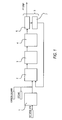
- FIG. 1 is a process flowchart of the synthesis gas production step of a GTL process in the first embodiment of the present invention. Note, however, that FIG. 1 does not show all the process flowchart of the synthesis gas production step. It mainly shows the part of the process flowchart relating to the flow of carbon dioxide in the synthesis gas production step. Therefore, also note that the part of the process flowchart relating to separating the steam contained in the synthesis gas produced in the synthesis gas production step is not shown in FIG. 1 .
- the synthesis gas production step mainly includes a desulfurization step having a desulfurization apparatus 1 and a synthesis gas production apparatus 2 and a decarbonation step having a decarbonation apparatus 5.
- the desulfurization apparatus 1 removes the sulfur component contained in natural gas.
- the synthesis gas production apparatus 2 produces synthesis gas by subjecting the natural gas introduced from the desulfurization apparatus 1 to a reforming reaction with gas containing steam and/or carbon dioxide.
- a reforming reaction is a reaction for producing synthesis gas containing mainly hydrogen and carbon monoxide by causing natural gas to react with steam and/or carbon dioxide.
- the number of mols of carbon originating from hydrocarbons that are raw material to be introduced into the synthesis gas production step is represented by C
- steam and/or carbon dioxide are added so as to make the H 2 O/C mol ratio that is the ratio of the number of mols of steam (H 2 O) to 1 mol of carbon show a value between 0.1 and 3.0 and/or the CO 2 /C mol ratio that is the ratio of the number of mols of carbon dioxide (CO 2 ) to 1 mol of carbon show a value between 0.1 and 3.0
- the H 2 O/C mol ratio show a value between 0.3 and 2.0 and/or the CO 2 /C mol ratio show a value between 0.3 and 1.0.
- a steam reforming method is a method of producing synthesis gas by adding steam to natural gas according to the reaction formula (1) shown below.
- a carbon dioxide reforming method is a method of producing synthesis gas by adding carbon dioxide to natural gas or using carbon dioxide contained in natural gas according to the reaction formula (2) shown below. Note that the reforming reactions of methane that is contained in natural gas as main component is shown as examples in the following formulas. formula (1): CH 4 + H 2 O ⁇ CO + 3H 2 formula (2): CH 4 + CO 2 ⁇ 2CO + 2H 2
- This arrangement is preferable because it eliminates the subsequent adjustment operation that is otherwise necessary.
- a large number of reaction tubes are installed in the synthesis gas production apparatus 2 and filled with a reforming catalyst that accelerates the above reforming reactions.
- a reforming catalyst formed by supporting a VIII group metal on an alkaline-earth metal oxide carrier can suitably be employed.
- Fuel (normally natural gas) and air are supplied into the synthesis gas production apparatus 2 and the group of reaction tubes installed in the synthesis gas production apparatus 2 is externally heated by burning the fuel by means of burners. Then, as the group of reaction tubes is heated in the synthesis gas production apparatus 2, the natural gas and the gas containing steam and/or carbon dioxide that flows in the reaction tubes are subjected to a reforming reaction in the presence of the reforming catalyst to produce synthesis gas containing hydrogen and carbon monoxide.
- the synthesis gas produced in the group of reaction tubes in the synthesis gas production apparatus 2 is cooled by a waste heat boiler 3 and a synthesis gas cooler 4 and subsequently introduced into the carbon dioxide absorption tower 6 of the decarbonation apparatus 5.
- the decarbonation apparatus 5 has a carbon dioxide absorption tower 6 and a regeneration tower 7, and the carbon dioxide contained in the synthesis gas produced by the synthesis gas production apparatus 2 is separated and collected.
- the carbon dioxide absorption tower 6 absorbs the carbon dioxide in the synthesis gas supplied from the synthesis gas cooler 4 by means of an amine-based absorbent stored in the carbon dioxide absorption tower 6.
- the absorbent that absorbs the carbon dioxide is then introduced into the regeneration tower 7.
- the regeneration tower 7 strips the carbon dioxide to regenerate the absorbing solution by way of the reverse reaction of the formula (3) by heating the absorbent supplied from the carbon dioxide absorption tower 6 by means of steam and subjecting it to a stripping process.
- amines that can be used for absorbent for the purpose of the present invention while an aqueous solution containing primary amines such as monoethanolamine, secondary amines such as diglycolamine, tertiary amines such as methyldiethanolamine (MDEA) and so on can be used, an aqueous solution containing tertiary amines, particularly MDEA that has poorly corrosive action for metal materials is preferably used.
- the decarbonation apparatus 5 separates and collects the carbon dioxide contained in the synthesis gas. Thereafter, the synthesis gas from which the carbon dioxide is removed is fed to the FT step. The absorbent from which the carbon dioxide is removed is resupplied to the carbon dioxide absorption tower 6 and recycled as absorbent for the carbon dioxide absorption tower 6.
- a material that does not contain nickel is preferably used as filling material both for the carbon dioxide absorption tower 6 and the regeneration tower 7.
- a material selected from titanium, ceramics, and stainless steel such as SUS 410 that do not contain nickel or a combination of any of them is preferably used as filling material.
- the carbon dioxide that is separated and collected by the decarbonation apparatus 5 is introduced from the regeneration tower 7 into the synthesis gas production apparatus 2 and reutilized as source gas for the reforming reaction.
- the carbon dioxide component is reutilized as a substance for reforming natural gas in the synthesis gas production step.
- the nickel carbonyl concentration in the carbon dioxide separated and collected by the decarbonation apparatus 5 and recycled to the synthesis gas production apparatus 2 is preferably not higher than 0.05 ppmv in terms of nickel metal.
- the activity of the synthesis gas reforming catalyst is reduced when the nickel carbonyl concentration is not lower than 0.05 ppmv in terms of nickel metal.
- a nickel carbonyl adsorption apparatus 8 is installed in the carbon dioxide recycling line from the decarbonation apparatus 5 to the synthesis gas production apparatus 2 as shown in FIG. 2 in order to reduce the nickel carbonyl concentration to a level not higher than 0.05 ppmv by further removing the nickel carbonyl contained in the carbon dioxide.
- An apparatus filled with an adsorbent containing active carbon as main component is preferably employed for the nickel carbonyl adsorption apparatus.
- the operating conditions of the adsorption apparatus include a temperature between 250 °C and 400 °C, a pressure between 0.02 MPaG and 3.0 MPaG, and a gas hourly space velocity (GHSV) between 500 h -1 and 3,000 h -1 .
- GHSV gas hourly space velocity
- the adsorption operation can be conducted stably for a long period because nickel carbonyl is destructively adsorbed onto the active carbon as nickel metal.
- the concentration of the nickel carbonyl contained in the carbon dioxide that is separated and collected by the decarbonation apparatus 5 can be determined, for example, by removing the moisture content of the separated and collected carbon dioxide by means of calcium chloride, subsequently absorbing the nickel carbonyl by means of an iodine-ethanol solution cooled by trichloroethylene and dry ice, and measuring the obtained absorbing solution by means of inductively-coupled plasma mass spectrometry.
- the nickel carbonyl concentration in the carbon dioxide that is separated and collected by the decarbonation apparatus 5 and recycled to the synthesis gas production apparatus 2 is reduced to not higher than 0.05 ppmv in terms of nickel metal so that nickel is prevented from being introduced into the synthesis gas production apparatus and degradation of the reforming catalyst can be avoided.
- Synthesis gas was produced by introducing natural gas, to which steam and carbon dioxide were added to make the H 2 O/C mol ratio and the CO 2 /C mol ratio respectively equal to 1.1 and 0.4, into a reformer filled with a reforming catalyst formed by supporting a VIII group metal on an alkaline-earth metal oxide carrier under conditions of an inlet temperature of 500°C, an outlet temperature of 880°C, a pressure of 2.0 MPaG, and a GHSV of 3,000h -1 .
- the obtained synthesis gas (H 2 : 58%, CO: 28%, CO 2 : 7%, CH 4 : 7%) was then introduced into a carbon dioxide absorption tower 6 under conditions of a temperature of 40°C and a pressure of 2 MPaG in order to separate and collect CO 2 from the obtained synthesis gas.
- the carbon dioxide absorption tower 6 was of a filled tower type. In other words, it was filled with cascade mini-rings of SUS410, which is a stainless steel material containing no nickel.
- the introduced synthesis gas was brought into gas/liquid contact with an aqueous solution containing MDEA, which is a tertiary amine, countercurrently. As a result, the carbon dioxide was absorbed and removed.
- the absorbent that absorbed carbon dioxide was then heat-exchanged with the hot absorbent that was being recycled from a regeneration tower 7 to the carbon dioxide absorption tower, and subsequently introduced into the regeneration tower 7 filled with SUS410 at a temperature of 100°C under a pressure of 0.1 MPaG.
- the carbon dioxide in the absorbent was stripped.
- the stripped carbon dioxide was then cooled to 40°C under 0.08 MPaG.
- the nickel carbonyl concentration in the collected carbon dioxide was 0.04 ppmv in terms of nickel metal.
- Synthesis gas (H 2 : 58%, CO: 28%, CO 2 : 7%, CH 4 : 7%) obtained by a synthesis gas production step same as that of Example 1 was introduced into a carbon dioxide absorption tower 6 under conditions of a temperature of 40°C and a pressure of 2 MPaG in order to separate and collect CO 2 from the obtained synthesis gas.
- the carbon dioxide absorption tower 6 was filled with cascade mini-rings of SUS304 which is a stainless steel material containing nickel.
- the introduced synthesis gas was brought into gas/liquid contact with an aqueous solution containing monoethanolamine, which is a primary amine, countercurrently. As a result, the carbon dioxide was absorbed and removed.
- the absorbent that absorbed carbon dioxide was then heat-exchanged with the hot absorbent that was being recycled from a regeneration tower 7 to the carbon dioxide absorption tower, and subsequently introduced into the regeneration tower 7 filled with SUS304 at a temperature of 100°C under a pressure of 0.1 MPaG.
- the carbon dioxide in the absorbent was stripped.
- the stripped carbon dioxide was then cooled to 40°C under 0.08 MPaG.
- the nickel carbonyl concentration in the collected carbon dioxide was 2.0 ppmv in terms of nickel metal.
- the pressure of the carbon dioxide (the nickel carbonyl concentration was 2.0 ppmv in terms of nickel metal) collected in Comparative Example 1 was raised to 2.2 MPaG and subsequently the carbon dioxide was heated to 250°C.
- the heated carbon dioxide was made to pass through an adsorption apparatus filled with a nickel carbonyl adsorbing material (Actisorb400: tradename, available from Süd-Chemie Catalysts) at a GHSV of 1,500h -1 .
- Actisorb400 tradename, available from Süd-Chemie Catalysts
Landscapes
- Chemical & Material Sciences (AREA)
- Chemical Kinetics & Catalysis (AREA)
- Organic Chemistry (AREA)
- Engineering & Computer Science (AREA)
- Oil, Petroleum & Natural Gas (AREA)
- Combustion & Propulsion (AREA)
- General Chemical & Material Sciences (AREA)
- Inorganic Chemistry (AREA)
- Health & Medical Sciences (AREA)
- General Health & Medical Sciences (AREA)
- Hydrogen, Water And Hydrids (AREA)
- Gas Separation By Absorption (AREA)
- Production Of Liquid Hydrocarbon Mixture For Refining Petroleum (AREA)
- Organic Low-Molecular-Weight Compounds And Preparation Thereof (AREA)
Abstract
Description
- The present invention relates to a method of suppressing metal contamination of a synthesis gas production apparatus. More particularly, the present invention relates to a method of preventing nickel contamination of a synthesis gas production apparatus in a synthesis gas production step of a GTL (gas-to-liquid) process.
- Depletion of petroleum resources have been feared for a long period. Meanwhile, research efforts have been made for technologies of manufacturing various hydrocarbon oils such as naphtha, kerosene and gas oil by exploiting natural gas, coal and alternative carbon sources such as biomass in order to reduce the degree of dependence upon petroleum resources. Of such technologies, those of GTL processes have got to a practically feasible level. GTL plants of commercially feasible scales have already been constructed and started operations in areas abundantly producing natural gas. There are trends of constructing similar plants.
- A GTL process is for manufacturing various petroleum products such as naphtha, kerosene and gas oil by reforming natural gas containing methane (CH4) as main component to produce synthesis gas containing hydrogen (H2) and carbon monoxide (CO) as main components, producing so-called Fischer-Tropsch oil (FT oil) that is a mixture of various hydrocarbon oils containing heavy hydrocarbons by way of Fischer-Tropsch synthesis (FT synthesis) using the synthesis gas as raw material, and upgrading and refining the obtained FT oil. This, a GTL process is roughly a three step process including a synthesis gas production step (reforming step), a Fischer-Tropsch oil manufacturing step (FT step) and an upgrading step (UG step).
- When producing synthesis gas, firstly the sulfur compounds contained in the natural gas that is to be consumed as raw material are desulfurized in a desulfurization apparatus. Subsequently, steam and/or carbon dioxide are added to the desulfurized natural gas, which desulfurized natural gas is then introduced into a synthesis gas production apparatus (to be also referred to as "reformer" hereinafter) and heated. As a result, the reforming reaction proceeds in the reformer by the effect of the reforming catalyst filled in the reformer. Thus, synthesis gas is produced in this way. While the steam reforming method using steam is mainly employed for a reforming reaction, the carbon dioxide reforming method using carbon dioxide has been put to practical use in recent years. The use of the carbon dioxide reforming method provides an advantage that the synthesis gas production step can be conducted efficiently at low cost because the carbon dioxide contained in natural gas does not need to be separated and removed before the reforming reaction. Additionally, more carbon dioxide can be used as resource because the unreacted carbon dioxide and the generated carbon dioxide that are contained in the produced synthesis gas can be separated, collected and recycled to the synthesis gas production step so as to be reutilized for the carbon dioxide reforming method
- In the synthesis gas production step, the carbon dioxide contained in the synthesis gas produced by reforming of natural gas is separated and collected by means of chemical absorption method in a carbon dioxide separation/collection unit, and the collected carbon dioxide is recycled to the synthesis gas production apparatus as source gas for reforming natural gas. In the process of separating and collecting carbon dioxide by means of a chemical absorption method, the absorbing solution stored in the carbon dioxide separation/collection unit absorbs carbon dioxide. Normally, a stainless steel material that contains nickel has been used as filling material for the absorption tower and the regeneration tower of a carbon dioxide separation/collection unit. Also normally, an aqueous solution that contains primary amines has been used as absorbing solution. However, the inventors of the present invention have found that an aqueous solution containing primary amines that absorbs carbon dioxide corrodes the filling material of carbon dioxide separation/collection unit, which is a nickel-containing stainless steel material. The manufactured synthesis gas contains carbon monoxide, which reacts with the nickel component dissolved into the aqueous solution as a result of corrosion and the filling material in the carbon dioxide separation/collection unit to produce nickel carbonyl.
- The nickel carbonyl produced in the carbon dioxide separation/collection unit in this way is then supplied to the reformer along with the recycled carbon dioxide as source gas for reforming natural gas. Then, the nickel carbonyl supplied to the reformer adheres onto the reforming catalyst filled in the reformer and then carbon as a result of a side reaction of the reforming reaction is deposited and accumulated. Then, degradation of the catalyst activity of the reforming catalyst is feared. Additionally, the supplied nickel carbonyl can be decomposed to produce nickel metal, and then the nickel metal can adhere to the rotating machines such as compressors and the heat exchangers installed in the recycle line. Then, damages to those machines are feared because such damages can adversely affect the stable and long term operation of the machines.
- PTL 1: Japanese Patent Application Laid-Open No.
2001-342003 - In view of the above-identified circumstances, an object of the present invention is to reduce as the nickel carbonyl contained in the carbon dioxide as possible that is being recycled from the carbon dioxide separation/collection step to the synthesis gas production step, and prevent the reforming catalyst from being deteriorated due to causing the nickel to accelerate the carbon producing reaction in the reformer in the synthesis gas production step.
- According to the present invention, the above object is achieved by providing a method of suppressing metal contamination of a synthesis gas production apparatus operating for a GTL (gas-to-liquid) process, including: a synthesis gas production step of producing synthesis gas by causing natural gas and gas containing steam and/or carbon dioxide to react with each other for reforming in a synthesis gas production apparatus; a Fischer-Tropsch oil manufacturing step of manufacturing Fischer-Tropsch oil by subjecting the synthesis gas produced in the synthesis gas production step to a Fischer-Tropsch reaction and subsequently isolating a gaseous product from the Fischer-Tropsch reaction products; and an upgrading step of manufacturing various hydrocarbon oils by subjecting the Fischer-Tropsch oil manufactured in the Fischer-Tropsch oil manufacturing step to hydrotreatment and distillation, in which, at the time of separating and collecting a carbon dioxide contained in the synthesis gas produced in the synthesis gas production step and recycling the separated and collected carbon dioxide as source gas for the reforming reaction in the synthesis gas production step, a nickel concentration in the recycled carbon dioxide is not higher than 0.05 ppmv.
- Thus, according to the present invention, the nickel carbonyl concentration in the carbon dioxide recycled to the reformer in the synthesis gas production step of a GTL process is minimized and hence the carbon deposition and accumulation on the surface of the reforming catalyst for producing synthesis gas filled in the reformer is suppressed (prevented) to prevent the catalyst activity of the reforming catalyst from being degraded. Additionally, adhesion of nickel to the machines, such as compressors and heat exchangers, in the synthesis gas production step is suppressed (prevented) to allow the machines to stably operate for a long period.
-
- [
FIG. 1 ]
FIG. 1 is a process flowchart of the synthesis gas production step of a GTL process in the first embodiment of the present invention. - [
FIG. 2 ]
FIG. 2 is a process flowchart of the synthesis gas production step of a GTL process in the second embodiment of the present invention. - Now, the present invention will be described in greater detail by way of preferred embodiments of the invention. Note, however, that the present invention is by no means limited to the embodiments that are described below.
-
FIG. 1 is a process flowchart of the synthesis gas production step of a GTL process in the first embodiment of the present invention. Note, however, thatFIG. 1 does not show all the process flowchart of the synthesis gas production step. It mainly shows the part of the process flowchart relating to the flow of carbon dioxide in the synthesis gas production step. Therefore, also note that the part of the process flowchart relating to separating the steam contained in the synthesis gas produced in the synthesis gas production step is not shown inFIG. 1 . - Referring to
FIG. 1 , the synthesis gas production step mainly includes a desulfurization step having a desulfurization apparatus 1 and a synthesisgas production apparatus 2 and a decarbonation step having adecarbonation apparatus 5. The desulfurization apparatus 1 removes the sulfur component contained in natural gas. The synthesisgas production apparatus 2 produces synthesis gas by subjecting the natural gas introduced from the desulfurization apparatus 1 to a reforming reaction with gas containing steam and/or carbon dioxide. A reforming reaction is a reaction for producing synthesis gas containing mainly hydrogen and carbon monoxide by causing natural gas to react with steam and/or carbon dioxide. - If the number of mols of carbon originating from hydrocarbons that are raw material to be introduced into the synthesis gas production step is represented by C, steam and/or carbon dioxide are added so as to make the H2O/C mol ratio that is the ratio of the number of mols of steam (H2O) to 1 mol of carbon show a value between 0.1 and 3.0 and/or the CO2/C mol ratio that is the ratio of the number of mols of carbon dioxide (CO2) to 1 mol of carbon show a value between 0.1 and 3.0, preferably to make the H2O/C mol ratio show a value between 0.3 and 2.0 and/or the CO2/C mol ratio show a value between 0.3 and 1.0.
- A steam reforming method is a method of producing synthesis gas by adding steam to natural gas according to the reaction formula (1) shown below. A carbon dioxide reforming method is a method of producing synthesis gas by adding carbon dioxide to natural gas or using carbon dioxide contained in natural gas according to the reaction formula (2) shown below. Note that the reforming reactions of methane that is contained in natural gas as main component is shown as examples in the following formulas.
formula (1): CH4 + H2O → CO + 3H2
formula (2): CH4 + CO2 → 2CO + 2H2
- In this embodiment, a steam reforming method and a carbon dioxide reforming method are used concurrently so that the ratio of the H2 to the CO that are produced can be adjusted so as to become close to the ratio of H2/CO = 2.0, which is preferable for a Fischer-Tropsch reaction. This arrangement is preferable because it eliminates the subsequent adjustment operation that is otherwise necessary.
- A large number of reaction tubes are installed in the synthesis
gas production apparatus 2 and filled with a reforming catalyst that accelerates the above reforming reactions. A reforming catalyst formed by supporting a VIII group metal on an alkaline-earth metal oxide carrier can suitably be employed. Fuel (normally natural gas) and air are supplied into the synthesisgas production apparatus 2 and the group of reaction tubes installed in the synthesisgas production apparatus 2 is externally heated by burning the fuel by means of burners. Then, as the group of reaction tubes is heated in the synthesisgas production apparatus 2, the natural gas and the gas containing steam and/or carbon dioxide that flows in the reaction tubes are subjected to a reforming reaction in the presence of the reforming catalyst to produce synthesis gas containing hydrogen and carbon monoxide. - The synthesis gas produced in the group of reaction tubes in the synthesis
gas production apparatus 2 is cooled by awaste heat boiler 3 and asynthesis gas cooler 4 and subsequently introduced into the carbondioxide absorption tower 6 of thedecarbonation apparatus 5. Thedecarbonation apparatus 5 has a carbondioxide absorption tower 6 and aregeneration tower 7, and the carbon dioxide contained in the synthesis gas produced by the synthesisgas production apparatus 2 is separated and collected. The carbondioxide absorption tower 6 absorbs the carbon dioxide in the synthesis gas supplied from thesynthesis gas cooler 4 by means of an amine-based absorbent stored in the carbondioxide absorption tower 6. - The carbon dioxide absorption reaction using the aqueous solution of amines is represented by the reaction formula (3) shown below. Thus, the carbon dioxide is absorbed as hydrogen carbonate ions.
formula (3): R-NH2 + CO2 + H2O → R-NH3 - + HCO3 -
- The absorbent that absorbs the carbon dioxide is then introduced into the
regeneration tower 7. Theregeneration tower 7 strips the carbon dioxide to regenerate the absorbing solution by way of the reverse reaction of the formula (3) by heating the absorbent supplied from the carbondioxide absorption tower 6 by means of steam and subjecting it to a stripping process. As for amines that can be used for absorbent for the purpose of the present invention, while an aqueous solution containing primary amines such as monoethanolamine, secondary amines such as diglycolamine, tertiary amines such as methyldiethanolamine (MDEA) and so on can be used, an aqueous solution containing tertiary amines, particularly MDEA that has poorly corrosive action for metal materials is preferably used. Thus, thedecarbonation apparatus 5 separates and collects the carbon dioxide contained in the synthesis gas. Thereafter, the synthesis gas from which the carbon dioxide is removed is fed to the FT step. The absorbent from which the carbon dioxide is removed is resupplied to the carbondioxide absorption tower 6 and recycled as absorbent for the carbondioxide absorption tower 6. - A material that does not contain nickel is preferably used as filling material both for the carbon
dioxide absorption tower 6 and theregeneration tower 7. A material selected from titanium, ceramics, and stainless steel such as SUS 410 that do not contain nickel or a combination of any of them is preferably used as filling material. - The carbon dioxide that is separated and collected by the
decarbonation apparatus 5 is introduced from theregeneration tower 7 into the synthesisgas production apparatus 2 and reutilized as source gas for the reforming reaction. In other words, the carbon dioxide component is reutilized as a substance for reforming natural gas in the synthesis gas production step. - The nickel carbonyl concentration in the carbon dioxide separated and collected by the
decarbonation apparatus 5 and recycled to the synthesisgas production apparatus 2 is preferably not higher than 0.05 ppmv in terms of nickel metal. The activity of the synthesis gas reforming catalyst is reduced when the nickel carbonyl concentration is not lower than 0.05 ppmv in terms of nickel metal. - If the nickel carbonyl concentration in the carbon dioxide separated and collected by the
decarbonation apparatus 5 is not lower than 0.05 ppmv in terms of nickel metal, preferably a nickelcarbonyl adsorption apparatus 8 is installed in the carbon dioxide recycling line from thedecarbonation apparatus 5 to the synthesisgas production apparatus 2 as shown inFIG. 2 in order to reduce the nickel carbonyl concentration to a level not higher than 0.05 ppmv by further removing the nickel carbonyl contained in the carbon dioxide. An apparatus filled with an adsorbent containing active carbon as main component is preferably employed for the nickel carbonyl adsorption apparatus. The operating conditions of the adsorption apparatus include a temperature between 250 °C and 400 °C, a pressure between 0.02 MPaG and 3.0 MPaG, and a gas hourly space velocity (GHSV) between 500 h-1 and 3,000 h-1. - When an adsorbent containing active carbon as main component is employed to adsorb nickel carbonyl under the above operating conditions, the adsorption operation can be conducted stably for a long period because nickel carbonyl is destructively adsorbed onto the active carbon as nickel metal.
- The concentration of the nickel carbonyl contained in the carbon dioxide that is separated and collected by the
decarbonation apparatus 5 can be determined, for example, by removing the moisture content of the separated and collected carbon dioxide by means of calcium chloride, subsequently absorbing the nickel carbonyl by means of an iodine-ethanol solution cooled by trichloroethylene and dry ice, and measuring the obtained absorbing solution by means of inductively-coupled plasma mass spectrometry. - With the above-described configuration, the nickel carbonyl concentration in the carbon dioxide that is separated and collected by the
decarbonation apparatus 5 and recycled to the synthesisgas production apparatus 2 is reduced to not higher than 0.05 ppmv in terms of nickel metal so that nickel is prevented from being introduced into the synthesis gas production apparatus and degradation of the reforming catalyst can be avoided. - Now, the present invention will be described further by way of examples. However, it should be noted that the present invention is by no means limited by these example.
- Synthesis gas was produced by introducing natural gas, to which steam and carbon dioxide were added to make the H2O/C mol ratio and the CO2/C mol ratio respectively equal to 1.1 and 0.4, into a reformer filled with a reforming catalyst formed by supporting a VIII group metal on an alkaline-earth metal oxide carrier under conditions of an inlet temperature of 500°C, an outlet temperature of 880°C, a pressure of 2.0 MPaG, and a GHSV of 3,000h-1. The obtained synthesis gas (H2: 58%, CO: 28%, CO2: 7%, CH4: 7%) was then introduced into a carbon
dioxide absorption tower 6 under conditions of a temperature of 40°C and a pressure of 2 MPaG in order to separate and collect CO2 from the obtained synthesis gas. The carbondioxide absorption tower 6 was of a filled tower type. In other words, it was filled with cascade mini-rings of SUS410, which is a stainless steel material containing no nickel. The introduced synthesis gas was brought into gas/liquid contact with an aqueous solution containing MDEA, which is a tertiary amine, countercurrently. As a result, the carbon dioxide was absorbed and removed. The absorbent that absorbed carbon dioxide was then heat-exchanged with the hot absorbent that was being recycled from aregeneration tower 7 to the carbon dioxide absorption tower, and subsequently introduced into theregeneration tower 7 filled with SUS410 at a temperature of 100°C under a pressure of 0.1 MPaG. Thus, the carbon dioxide in the absorbent was stripped. The stripped carbon dioxide was then cooled to 40°C under 0.08 MPaG. The nickel carbonyl concentration in the collected carbon dioxide was 0.04 ppmv in terms of nickel metal. - Synthesis gas (H2: 58%, CO: 28%, CO2: 7%, CH4: 7%) obtained by a synthesis gas production step same as that of Example 1 was introduced into a carbon
dioxide absorption tower 6 under conditions of a temperature of 40°C and a pressure of 2 MPaG in order to separate and collect CO2 from the obtained synthesis gas. The carbondioxide absorption tower 6 was filled with cascade mini-rings of SUS304 which is a stainless steel material containing nickel. The introduced synthesis gas was brought into gas/liquid contact with an aqueous solution containing monoethanolamine, which is a primary amine, countercurrently. As a result, the carbon dioxide was absorbed and removed. The absorbent that absorbed carbon dioxide was then heat-exchanged with the hot absorbent that was being recycled from aregeneration tower 7 to the carbon dioxide absorption tower, and subsequently introduced into theregeneration tower 7 filled with SUS304 at a temperature of 100°C under a pressure of 0.1 MPaG. Thus, the carbon dioxide in the absorbent was stripped. The stripped carbon dioxide was then cooled to 40°C under 0.08 MPaG. The nickel carbonyl concentration in the collected carbon dioxide was 2.0 ppmv in terms of nickel metal. - The pressure of the carbon dioxide (the nickel carbonyl concentration was 2.0 ppmv in terms of nickel metal) collected in Comparative Example 1 was raised to 2.2 MPaG and subsequently the carbon dioxide was heated to 250°C. The heated carbon dioxide was made to pass through an adsorption apparatus filled with a nickel carbonyl adsorbing material (Actisorb400: tradename, available from Süd-Chemie Catalysts) at a GHSV of 1,500h-1. As a result, the nickel carbonyl concentration in the carbon dioxide was reduced to 0.02 ppmv in terms of nickel metal.
- This application claims the benefit of Japanese Patent Application No.
2011-078808, filed March 31, 2011 -
- 1:
- desulfurization apparatus
- 2:
- synthesis gas production apparatus
- 3:
- waste heat boiler
- 4:
- synthesis gas cooler
- 5:
- decarbonation apparatus
- 6:
- carbon dioxide absorption tower
- 7:
- regeneration tower
- 8:
- adsorption apparatus
Claims (5)
- A method of suppressing metal contamination of a synthesis gas production apparatus operating for a GTL (gas-to-liquid) process, comprising:a synthesis gas production step of producing synthesis gas by causing natural gas and gas containing steam and/or carbon dioxide to react with each other for reforming in a synthesis gas production apparatus;a Fischer-Tropsch oil manufacturing step of manufacturing Fischer-Tropsch oil by subjecting the synthesis gas produced in the synthesis gas production step to a Fischer-Tropsch reaction and subsequently isolating a gaseous product from the Fischer-Tropsch reaction products; andan upgrading step of manufacturing various hydrocarbon oils by subjecting the Fischer-Tropsch oil manufactured in the Fischer-Tropsch oil manufacturing step to hydrotreatment and distillation, whereinat the time of separating and collecting a carbon dioxide contained in the synthesis gas produced in the synthesis gas production step and recycling the separated and collected carbon dioxide as source gas for the reforming reaction in the synthesis gas production step, a nickel concentration in the recycled carbon dioxide is not higher than 0.05 ppmv.
- The method according to claim 1, wherein the carbon dioxide in the synthesis gas is separated and collected by an aqueous solution containing a tertiary amine.
- The method according to claim 1 or 2, wherein the carbon dioxide in the synthesis gas is separated and collected by a decarbonation apparatus filled with a filling material of a material containing no nickel.
- The method according to any one of claims 1 to 3, wherein the separated and collected carbon dioxide is introduced into an adsorption apparatus having an adsorbent containing active carbon as main component at a temperature between 250 °C and 400 °C under a pressure between 0.02 MPaG and 3.0 MPaG and a gas hourly space velocity between 500 h-1 and 3,000 h-1 and subsequently introduced into the synthesis gas production apparatus.
- The method according to any one of claims 1 to 4, wherein the gas supplied to the synthesis gas production apparatus shows a H2O/C mol ratio between 0.1 and 3.0 and/or a CO2/C mol ratio between 0.1 and 3.0.
Applications Claiming Priority (2)
| Application Number | Priority Date | Filing Date | Title |
|---|---|---|---|
| JP2011078808A JP5804747B2 (en) | 2011-03-31 | 2011-03-31 | Method for suppressing metal contamination in syngas production equipment |
| PCT/JP2012/001966 WO2012132337A1 (en) | 2011-03-31 | 2012-03-22 | Method for controlling mixing in of metal in apparatus for manufacturing synthetic gas |
Publications (2)
| Publication Number | Publication Date |
|---|---|
| EP2692690A1 true EP2692690A1 (en) | 2014-02-05 |
| EP2692690A4 EP2692690A4 (en) | 2014-08-27 |
Family
ID=46930121
Family Applications (1)
| Application Number | Title | Priority Date | Filing Date |
|---|---|---|---|
| EP12765528.0A Withdrawn EP2692690A4 (en) | 2011-03-31 | 2012-03-22 | METHOD FOR CONTROLLING THE INCORPORATION OF METAL IN AN APPARATUS FOR PRODUCING SYNTHETIC GAS |
Country Status (12)
| Country | Link |
|---|---|
| US (2) | US9725656B2 (en) |
| EP (1) | EP2692690A4 (en) |
| JP (1) | JP5804747B2 (en) |
| CN (1) | CN103582610B (en) |
| AP (1) | AP3483A (en) |
| AU (1) | AU2012235395B2 (en) |
| BR (1) | BR112013025187B8 (en) |
| CA (1) | CA2831561C (en) |
| EA (2) | EA035192B1 (en) |
| MY (1) | MY175361A (en) |
| WO (1) | WO2012132337A1 (en) |
| ZA (1) | ZA201307218B (en) |
Cited By (1)
| Publication number | Priority date | Publication date | Assignee | Title |
|---|---|---|---|---|
| EP3075706A1 (en) * | 2015-03-31 | 2016-10-05 | Linde Aktiengesellschaft | Method and a plant for the production of synthesis gas |
Families Citing this family (6)
| Publication number | Priority date | Publication date | Assignee | Title |
|---|---|---|---|---|
| US10906808B2 (en) | 2017-11-15 | 2021-02-02 | Gas Technology Institute | Noble metal catalysts and processes for reforming of methane and other hydrocarbons |
| US10738247B2 (en) | 2017-11-15 | 2020-08-11 | Gas Technology Institute | Processes and systems for reforming of methane and light hydrocarbons to liquid hydrocarbon fuels |
| KR20250048117A (en) * | 2017-11-15 | 2025-04-07 | 지티아이 에너지 | Processes and systems for reforming of methane and light hydrocarbons to liquid hydrocarbon fuels |
| FI3710400T3 (en) * | 2017-11-15 | 2023-12-14 | Gas Technology Inst | A method for methane reforming |
| US11111142B2 (en) | 2018-09-18 | 2021-09-07 | Gas Technology Institute | Processes and catalysts for reforming of impure methane-containing feeds |
| US12122962B2 (en) | 2018-09-18 | 2024-10-22 | Gti Energy | Processes and catalysts for reforming of impure methane-containing feeds |
Family Cites Families (19)
| Publication number | Priority date | Publication date | Assignee | Title |
|---|---|---|---|---|
| CA1287732C (en) | 1984-03-19 | 1991-08-20 | Clifton S. Goddin, Jr. | Process and apparatus for low temperature amine removal of acid gases |
| US5232596A (en) * | 1991-10-07 | 1993-08-03 | Radian Corporation | Bio-slurry reaction system and process for hazardous waste treatment |
| JP3233802B2 (en) | 1994-12-15 | 2001-12-04 | 関西電力株式会社 | Method for removing carbon dioxide and nitrogen oxides from flue gas |
| ES2221749T3 (en) * | 1998-07-08 | 2005-01-01 | Shell Internationale Research Maatschappij B.V. | CARBON METAL EXTRACTION PROCEDURE FROM A GASEOUS FLOW. |
| JP4681101B2 (en) | 2000-05-30 | 2011-05-11 | 三菱重工業株式会社 | Method for producing synthesis gas for gasoline, light oil and kerosene |
| US6489370B2 (en) * | 2000-05-30 | 2002-12-03 | Mitsubishi Heavy Industries, Ltd. | Method of manufacturing a synthesis gas to be employed for the synthesis of gasoline, kerosene and gas oil |
| AU2003214041B2 (en) * | 2002-01-14 | 2008-10-02 | Shell Internationale Research Maatschappij B.V. | Process for removing carbon dioxide from gas mixtures |
| US6596781B1 (en) * | 2002-05-02 | 2003-07-22 | Chevron U.S.A. Inc. | Integrated process for preparing Fischer-Tropsch products and acetic acid from synthesis gas |
| FR2856049B1 (en) * | 2003-06-11 | 2006-08-18 | Air Liquide | PURIFICATION OF A H2 / CO MIXTURE BY CATALYSIS OF IMPURITIES |
| US7507326B2 (en) | 2003-11-14 | 2009-03-24 | Chevron U.S.A. Inc. | Process for the upgrading of the products of Fischer-Tropsch processes |
| WO2007114277A1 (en) * | 2006-03-30 | 2007-10-11 | Nippon Steel Engineering Co., Ltd. | Liquid fuel synthesis system |
| AU2007232922B2 (en) | 2006-03-30 | 2010-12-09 | Nippon Steel Engineering Co., Ltd. | Liquid fuel synthesis system |
| WO2008037726A1 (en) * | 2006-09-27 | 2008-04-03 | Shell Internationale Research Maatschappij B.V. | Process for removal of metal carbonyls from a synthesis gas stream |
| KR101512672B1 (en) | 2006-12-08 | 2015-04-16 | 쉘 인터내셔날 리써취 마트샤피지 비.브이. | The process of producing the purified syngas stream |
| FR2918579B1 (en) | 2007-07-13 | 2010-01-01 | Air Liquide | PROCESS FOR PURIFYING CO2-CONTAINING GAS BY INTEGRATION OF ADSORPTION PURIFICATION UNIT |
| JP5424566B2 (en) | 2008-03-14 | 2014-02-26 | 独立行政法人石油天然ガス・金属鉱物資源機構 | Method for producing synthesis gas in liquid hydrocarbon production process from natural gas |
| MY153983A (en) | 2008-09-30 | 2015-04-30 | Japan Oil Gas & Metals Jogmec | Hydrocarbon synthesis reaction apparatus, hydrocarbon synthesis reaction system, and hydrocarbon synthesizing method |
| JP5301330B2 (en) | 2009-03-27 | 2013-09-25 | 独立行政法人石油天然ガス・金属鉱物資源機構 | Liquid hydrocarbon synthesis method and liquid hydrocarbon synthesis system |
| JP5501366B2 (en) * | 2009-08-31 | 2014-05-21 | 独立行政法人石油天然ガス・金属鉱物資源機構 | Hydrocarbon synthesis reaction apparatus, hydrocarbon synthesis reaction system, and hydrocarbon synthesis reaction method |
-
2011
- 2011-03-31 JP JP2011078808A patent/JP5804747B2/en not_active Expired - Fee Related
-
2012
- 2012-03-22 AU AU2012235395A patent/AU2012235395B2/en not_active Ceased
- 2012-03-22 BR BR112013025187A patent/BR112013025187B8/en not_active IP Right Cessation
- 2012-03-22 MY MYPI2013701817A patent/MY175361A/en unknown
- 2012-03-22 CN CN201280015601.9A patent/CN103582610B/en not_active Expired - Fee Related
- 2012-03-22 US US14/008,509 patent/US9725656B2/en not_active Expired - Fee Related
- 2012-03-22 EA EA201891476A patent/EA035192B1/en not_active IP Right Cessation
- 2012-03-22 CA CA2831561A patent/CA2831561C/en active Active
- 2012-03-22 WO PCT/JP2012/001966 patent/WO2012132337A1/en not_active Ceased
- 2012-03-22 EA EA201391434A patent/EA031520B1/en not_active IP Right Cessation
- 2012-03-22 AP AP2013007174A patent/AP3483A/en active
- 2012-03-22 EP EP12765528.0A patent/EP2692690A4/en not_active Withdrawn
-
2013
- 2013-09-26 ZA ZA2013/07218A patent/ZA201307218B/en unknown
-
2016
- 2016-06-01 US US15/170,123 patent/US9884998B2/en not_active Expired - Fee Related
Cited By (1)
| Publication number | Priority date | Publication date | Assignee | Title |
|---|---|---|---|---|
| EP3075706A1 (en) * | 2015-03-31 | 2016-10-05 | Linde Aktiengesellschaft | Method and a plant for the production of synthesis gas |
Also Published As
| Publication number | Publication date |
|---|---|
| CA2831561C (en) | 2016-04-19 |
| EA201891476A1 (en) | 2019-03-29 |
| US20140018450A1 (en) | 2014-01-16 |
| EP2692690A4 (en) | 2014-08-27 |
| US20160272895A1 (en) | 2016-09-22 |
| JP5804747B2 (en) | 2015-11-04 |
| BR112013025187B1 (en) | 2022-03-03 |
| AU2012235395A1 (en) | 2013-10-31 |
| EA201391434A1 (en) | 2014-01-30 |
| BR112013025187B8 (en) | 2022-08-02 |
| MY175361A (en) | 2020-06-22 |
| BR112013025187A2 (en) | 2021-03-23 |
| AU2012235395B2 (en) | 2015-04-16 |
| EA035192B1 (en) | 2020-05-12 |
| JP2012214529A (en) | 2012-11-08 |
| CN103582610A (en) | 2014-02-12 |
| AP2013007174A0 (en) | 2013-10-31 |
| CN103582610B (en) | 2017-07-04 |
| ZA201307218B (en) | 2014-06-25 |
| WO2012132337A1 (en) | 2012-10-04 |
| EA031520B1 (en) | 2019-01-31 |
| AP3483A (en) | 2015-12-31 |
| CA2831561A1 (en) | 2012-10-04 |
| US9884998B2 (en) | 2018-02-06 |
| US9725656B2 (en) | 2017-08-08 |
Similar Documents
| Publication | Publication Date | Title |
|---|---|---|
| US9884998B2 (en) | Method of suppressing metal contamination of synthesis gas production apparatus | |
| CN104094461B (en) | For generating electricity and improving the system and method for oil recovery | |
| US9056772B2 (en) | Method for producing synthesis gas | |
| JP5301330B2 (en) | Liquid hydrocarbon synthesis method and liquid hydrocarbon synthesis system | |
| WO2017127122A1 (en) | Conversion of waste co2 into useful transport fuels using steam methane reformer in a gas to liquids plant | |
| WO2013017700A1 (en) | Process for producing hydrocarbons from syngas | |
| KR102330626B1 (en) | Method for purifying synthetic gas by amine scrubbing using aqueous amine solutions | |
| Docekal | Hydrogen production from hydrocarbons | |
| US8832967B2 (en) | Method for removing sulfur compounds in castable | |
| US8883036B2 (en) | Hydrogen sulfide stream for catalyst sulfidation from refinery rich amines | |
| CN103483119B (en) | Method for producing methanefrom hydrogen-rich synthetic gas | |
| Monteleone et al. | Fuel gas clean-up and conditioning |
Legal Events
| Date | Code | Title | Description |
|---|---|---|---|
| PUAI | Public reference made under article 153(3) epc to a published international application that has entered the european phase |
Free format text: ORIGINAL CODE: 0009012 |
|
| 17P | Request for examination filed |
Effective date: 20131015 |
|
| AK | Designated contracting states |
Kind code of ref document: A1 Designated state(s): AL AT BE BG CH CY CZ DE DK EE ES FI FR GB GR HR HU IE IS IT LI LT LU LV MC MK MT NL NO PL PT RO RS SE SI SK SM TR |
|
| DAX | Request for extension of the european patent (deleted) | ||
| A4 | Supplementary search report drawn up and despatched |
Effective date: 20140730 |
|
| RIC1 | Information provided on ipc code assigned before grant |
Ipc: C10G 2/00 20060101ALI20140724BHEP Ipc: C01B 3/38 20060101ALI20140724BHEP Ipc: C10G 49/00 20060101ALI20140724BHEP Ipc: C01B 31/20 20060101AFI20140724BHEP Ipc: C01B 3/52 20060101ALI20140724BHEP |
|
| STAA | Information on the status of an ep patent application or granted ep patent |
Free format text: STATUS: THE APPLICATION HAS BEEN WITHDRAWN |
|
| 18W | Application withdrawn |
Effective date: 20190704 |