EP2692641A2 - Aircraft electrical mat with solderless lead line connections - Google Patents
Aircraft electrical mat with solderless lead line connections Download PDFInfo
- Publication number
- EP2692641A2 EP2692641A2 EP13178840.8A EP13178840A EP2692641A2 EP 2692641 A2 EP2692641 A2 EP 2692641A2 EP 13178840 A EP13178840 A EP 13178840A EP 2692641 A2 EP2692641 A2 EP 2692641A2
- Authority
- EP
- European Patent Office
- Prior art keywords
- electrical
- mat
- set forth
- bus
- fastener
- Prior art date
- Legal status (The legal status is an assumption and is not a legal conclusion. Google has not performed a legal analysis and makes no representation as to the accuracy of the status listed.)
- Withdrawn
Links
Images






















Classifications
-
- H—ELECTRICITY
- H05—ELECTRIC TECHNIQUES NOT OTHERWISE PROVIDED FOR
- H05B—ELECTRIC HEATING; ELECTRIC LIGHT SOURCES NOT OTHERWISE PROVIDED FOR; CIRCUIT ARRANGEMENTS FOR ELECTRIC LIGHT SOURCES, IN GENERAL
- H05B3/00—Ohmic-resistance heating
- H05B3/02—Details
- H05B3/06—Heater elements structurally combined with coupling elements or holders
-
- B—PERFORMING OPERATIONS; TRANSPORTING
- B64—AIRCRAFT; AVIATION; COSMONAUTICS
- B64D—EQUIPMENT FOR FITTING IN OR TO AIRCRAFT; FLIGHT SUITS; PARACHUTES; ARRANGEMENT OR MOUNTING OF POWER PLANTS OR PROPULSION TRANSMISSIONS IN AIRCRAFT
- B64D15/00—De-icing or preventing icing on exterior surfaces of aircraft
- B64D15/12—De-icing or preventing icing on exterior surfaces of aircraft by electric heating
-
- H—ELECTRICITY
- H05—ELECTRIC TECHNIQUES NOT OTHERWISE PROVIDED FOR
- H05B—ELECTRIC HEATING; ELECTRIC LIGHT SOURCES NOT OTHERWISE PROVIDED FOR; CIRCUIT ARRANGEMENTS FOR ELECTRIC LIGHT SOURCES, IN GENERAL
- H05B3/00—Ohmic-resistance heating
- H05B3/20—Heating elements having extended surface area substantially in a two-dimensional [2D] plane, e.g. plate-heater
- H05B3/34—Heating elements having extended surface area substantially in a two-dimensional [2D] plane, e.g. plate-heater flexible, e.g. heating nets or webs
Definitions
- an aircraft will usually have one or more surfaces vulnerable to ice accumulation and thus equipped with some type of ice protection system.
- an ice protection mat is installed on the relevant aircraft surface.
- the mat typically comprises a heater comprising at least one electrically conductive path and a bus electrically connected to the conductive path.
- the bus is electrically connected via lead lines to a power source onboard the aircraft.
- An electrical mat is provided wherein the heater's busses can be electrically connected to lead lines with simple and standard fastening tools.
- the electrical connections to the aircraft onboard power source can be made without heat application in the vicinity of the busses, without post-lamination material removal steps, and/or and without requiring special worker skills, such as soldering.
- Figures 1-3 show an aircraft with electrical mats installed on some of its ice-vulnerable surfaces, a cross section of an ice-vulnerable surface, and a lead line for electrical connection of the mat to an onboard power source.
- Figures 4-80 show various views of the electrical mat, some possible embodiments for its inboard region, and method steps for making the same.
- the mats and inboard regions are shown in a flattened form, although they will often conform to an airfoil shape such as shown Figure 2 .
- layer thicknesses and fastener dimensions are greatly exaggerated, and probably not sized to scale.
- laminates and composites are sometimes shown with significant empty pockets or spaces between adjacent layers and elements, but this would not really be the case as the thinness of the elements and/or the tight spacing of the layers would preclude any noticeable voids thereamong.
- an aircraft 10 has components 11 with surfaces 12 which are vulnerable to ice accumulation.
- An electrical mat 20 is installed on each of the aircraft surfaces 12 and electrically connected to an onboard power source 13 via lead lines 30.
- Each lead line 30 can comprise, for example, a wire 31 with a standard ring terminal 32 coupled thereto.
- the terminal 32 has a crimp 33 crimped to the wire 31, a podium 34, and a ramp 35 attaching the crimp 33 to the podium 34.
- the podium 34 has a bondside connection face 36, a nonbondside face 37, and a central opening (i.e., a stem-receiving opening 134 introduced below) extending therethrough.
- the electrical mat 20 can comprise a plurality of layers 41-48.
- these layers include a nonbondside layer 41, an adhesive layer 42, a heater layer 43, a heater-support layer 44, another adhesive layer 45, and bondside layers 46-48.
- the electrical mat 20 can instead have fewer, more, and/or different layers, depending upon its intended application, design, fabrication, and/or other factors.
- the nonbondside layer 41 can comprise a thermoset polymer sheet (e.g., an epoxy polymer) having reinforcing fibers (e.g., fiberglass) embedded therein. Or it can comprise a metal sheet (e.g., stainless steel). In either or any event, the nonbondside layer 41 will preferably have a high coefficient of thermal transfer to encourage heat flow in the nonbondside direction. Also, if this layer 41 is exposed to the environment and ice will accumulate thereon, it may also be called upon to function as an erosion shield and moisture barrier.
- a thermoset polymer sheet e.g., an epoxy polymer
- reinforcing fibers e.g., fiberglass
- metal sheet e.g., stainless steel
- the adhesive layer 42 serves, in the illustrated embodiment, as an insulating layer around the heater layer 43, whereby it has dielectric qualities.
- the layer 42 can comprise, for example, a thermoset polymer adhesive (e.g., modified epoxy) with reinforcing fibers embedded therein.
- the adhesive layer 42 also insures a strong and secure bonding of the layers 41 and 43.
- the layer 43 can have thermal transfer properties akin to that of the nonbondside layer 41. However, the relative height of the adhesive layer 42 may be such that its thermal-transfer properties are dwarfed by those of the nonbondside sheet 41 and/or the bondside layers 46-48.
- the heater layer 43 comprises a heater element 50 having at least one electrically conductive path 51 with electrical resistance characteristics corresponding to a desired power output for ice protection purposes.
- a bus 52 is electrically connected to each end of the conductive path 51 so as to supply electrical power thereto and return it therefrom.
- the busses 52 can each comprise, for example, a thin sheet of metal (e.g., copper, gold, silver, etc) or other conductive material. Busses are typically located on an inboard region and they usually have a relatively low resistance relative to their connected-to conductive path 51.
- the heater-support layer 44 can comprise any dielectric material suitable for subassembly of the heater element 50, if the conductive paths 51 are etched, printed, laid, or otherwise subassembled on the heater-support layer 44 prior to layer lamination. If the bus-connected path 51 resides on a subassembled heater support layer 44, the busses 52 can also reside thereon and/or be subassembled therewith. If the heater element 50 instead depends upon a conductive sheet or fabric for its conductive paths 51, a heater-support layer 44 may not be necessary and/or the busses 52 may be integral with the heater element 50.
- the adhesive layer 45 can comprise a thermosetting polymer adhesive (e.g., modified epoxy) having the primary role to insure strong and secure bonding of the layers 43-44 to layer 46. It can preferably have electric insulation and/or thermal transfer properties akin to that of the bondside layers 46-48. But again, the thinness of the adhesive layer 45 relative to the bondside layers 46-48 may moot such properties.
- a thermosetting polymer adhesive e.g., modified epoxy
- the bondside layers 46-48 can each comprise a thermoset polymer sheet (e.g., an epoxy polymer) having reinforcing fibers (e.g., fiberglass) embedded therein.
- the layer 46 serves as an electric insulating layer around the heater layer 43, whereby at least it should have dielectric qualities.
- the bondside layers 46-48 preferably have a low coefficient of thermal transfer to discourage heat flow in the bondside direction. This can be accomplished, for example, by the layers 46-48 being made of less thermally-transferring material and/or by using multiple bondside layers.
- the electrical mat 20 is preferably made by compiling the layers 41-48 and then curing this compilation to create a composite or laminate.
- the nonbondside layer 41, the heater-support layer 44 and the bondside layers 46-48 can each begin as prepreg layer with a matrix polymer that is crosslinked during curing.
- the adhesive layers 42 and 45 can each begin as film capable of withstanding the prepregs' curing conditions.
- each bus 52 includes a connection face 53 for electrical connection to the connection face 36 of the lead line's terminal 32.
- connection face refers to a site on the topology of a bus 52, rather than a distinct segment or part. In most cases, there will be no structural distinction between the face 53 and the rest of the bus 52, other than the location of this site.
- a window 60 is associated with each bus 52 and aligned with its connection face 53.
- Each window 60 reaches through the thickness of the nonbondside layer 41 and any other layer (e.g., the adhesive film layer 42) located nonbondside of the heater layer 43.
- the window 60 preferably exists prior to layer lamination, to avoid post-lamination steps involving material removal near the busses 52.
- a fastener 70 is adapted to mechanically attach the lead line 30 to the electrical mat 20 in such a manner that its connection face 36 is electrically connected to the bus's connection face 53.
- the fastener 70 has stem 71 which extends through the window 60 and has external threads 72.
- the cross-sectional size of the stem 71 is such there is a generous gap 61 between it and window-defining edges. If the window 60 is circular, for example, the gap 61 will have annulus-like shape.
- the fastener 70 can have a head 73 on the bondside end of its stem 73.
- the head 73 is intended to sit substantially flush against one of the layers 40, whereby can preferably be made as thin as possible (e.g., less than 1.0mm, less than 0.5mm, and/or less than 0.35mm). Additionally or alternatively, the head 73 can have polygonal shape (e.g., hexagonal) so as to not encourage rotation relative to adjacent layers.
- the fastener stem 71 preferably has a standard construction while the fastener head 73 optimally has a much thinner than standard construction. Accordingly, one option for fastener fabrication is to modify the head of a standard fastener, filing it down to the desired thickness.
- the fastener 70 can comprise an off-the-shelf screw, a modified off-the-shelf screw, or a custom-machined component.
- the fastener heads 73 are situated bondside of the layer 48.
- the layers 43-48 have stem-receiving openings 143-148 aligned with each window 60, with the opening 143 being located centrally within the connection face 53 of the corresponding bus 52.
- the stem 71 of each fastener 70 extends, in the nonbondside direction, through the aligned window 60 and through the aligned fastener-receiving openings 143-148.
- the fastener heads 73 are situated bondside of the layer 47, and the fastener stems 71 extend through windows 60 and then through stem-receiving openings 143-147.
- the heads 73 are situated bondside of the layer 46 and the stems 71 extend through windows 60 and through openings 143-146. And in the inboard region 21 shown in Figure 9 , the heads 73 are situated bondside of the heater support layer 44, and the stems 71 extend through the windows 60 and through openings 144.
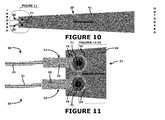
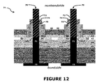
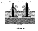
- the lead lines 30 are shown electrically connected to the inboard regions 21 in Figures 10-15 .
- the lead lines 30 are electrically connected via a standard nut 74 having interior threads 75.
- the nuts 74 can be off-the-shelf items and they can be tightened onto the fastener's stem 71 with a standard tool (e.g., a wrench).
- a standard tool e.g., a wrench
- electrical connection can be accomplished with standard tools which do not require special skills and/or which consistently perform regardless of worker experience.
- heat application on or near the busses 52 is not required, thereby eliminating the risk of thermal damage thereto
- the heater layer 43 can be subassembled on the support layer 44 so that the conductive path 51 and the busses 52 reside thereon ( Figure 16 ).
- Stem-receiving openings 143-144 can be produced on the subassembled heater layers 43-44 ( Figure 17 ).
- the windows 60 can created on the layers 41-42 nonbondside of the heater layer 43 ( Figure 18 ).
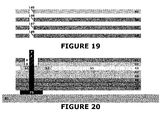
- the stem-receiving openings 145-148 are produced in the layers 45-48 ( Figure 19 ), the layers 41-48 are compiled on a build metal 81 with the fastener head 73 positioned below bondside layers 48 ( Figure 20 ).
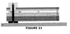
- a plug 82 is preferably inserted into the window 60 so as to preserve its dimensions ( Figure 21 ).
- the laminate can then be vacuum bagged and cured in a conventional manner.
- the laminate may be sandwiched between peel plies and/or release plies.
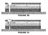
- the layers 41-48 can instead be compiled on the build metal 81 without the fasteners 70 ( Figure 30 ), the stem-receiving openings 145-148 filled with a plug 83 ( Figure 31 ), and the fasteners 70 inserted after curing and removal of the plugs 82-83 ( Figure 32-33 ).
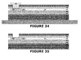
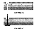
- the layers 41-48 can be compiled on the build metal 81 and cured without openings 145-148 ( Figure 34 ), the stem-receiving openings 145-148 produced in a post-curing step ( Figure 35 , and the fasteners 70 then inserted therethrough ( Figure 36-37 ).
- FIG. 38-43 Another electrical mat 20 and inboard region 21 is shown in Figures 38-43 .
- the fastener heads 73 are situated nonbondside of the heater layer 43 and mounted on a bus connection face 53 with a patch of electrically conductive adhesive 76.
- the lead lines 30 can again be mechanically attached to the stem 71 via a nut 74 having internal threads 75.
- the mat 20 depicted in Figures 38-43 can be made in the same manner as discussed above, absent the opening-producing steps and with the addition of patch-applying step.
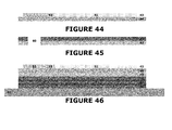
- the heater layer 43 can be subassembled on the support layer 44 ( Figure 44 ) and the windows 60 can created on the layers 41-42 nonbondside of the heater layer 43 ( Figure 45 ).
- the layers 43-48 are then compiled on the build metal 81 ( Figure 46 ), the adhesive patches 76 are placed on the busses' connection faces 53 ( Figure 47 ) and the fastener heads 73 are secured to the patches 76 ( Figure 48 ).
- the layers 41-42 are then compiled with the layers 43-48, with the fastener stems 71 extending through windows 60 ( Figure 49 ).
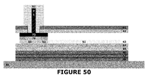
- a plug 82 is inserted into the window to preserve its dimensions ( Figure 50 ) and then the laminate can then vacuum bagged and cured in a conventional manner.
- FIG. 51-56 Another electrical mat 20 and inboard region 21 is shown in Figures 51-56 .
- the fastener nut 74 (with internal threads) is mounted on a bus connection face 53 with a patch of electrically conductive adhesive 76.
- the lead lines 30 can be mechanically attached to the nut 74 via a stem 72 having internal threads 73.
- the mat 20 can be made in the same manner as one discussed immediately above with the adhesively-attached head 73.
- additional laminate layers 91-93 may be necessary in the inboard region 21 to avoid over-protrusion of the nuts 74.
- a plug 84 can be positioned to preserve the nut's internal threads 75, rather than window dimensions.
- connection face 36 of the lead line 30 contacts the bus's connection face 53 to thereby directly establish electrical connection therewith.
- the fastener stem 71 does not participate in the electrical connection path, but instead merely mechanically holds the lead line 30 so that its connection face 36 contacts the bus connection face 53.
- the fastener head 73 and the fastener's nut 94 also do not participate in the electrical connection path in these embodiments.
- connection face 36 of the lead line 30 makes contact with the head 73 or the nut 74 of the fastener 70.
- Electrical connection with the bus's connection face 53 is made indirectly through the adhesive patch 76.
- the fastener stem 71 does not participate electrically in the electrical connection, but again merely mechanically holds the lead line 30 so that its connection face 36 contacts the bus connection face 53. In these embodiments, however, either the fastener head 73 or the fastener nut 74 participates electrically in the electrical connection of the lead line 30 to the bus 52.
- both fasteners 70 are positioned in the same manner for the two busses 52, but this need not be the case.
- An inboard region 21 having fasteners 70 positioned at different layer levels is feasible and foreseeable. Such a staggered positioning may be beneficial when the heater 50 has multiple conductive paths 51 (and thus multiple bus pairs). It may also help promote consistent thicknesses across the inboard region 21. And electrical mats 20 with both nonbondside and bondside electrical connections are certainly plausible and possible.
- the aircraft electrical mat 20 allows the heater's busses 52 to be electrically connected to the lead lines 30 with simple and standard fastening tools. These electrical connections can be accomplished without heat application near the busses 52 and/or without post-lamination material removal steps.
- the aircraft electrical mat 10 can be delivered to the customer (e.g., an aircraft manufacturer), wrapped in instructional peel plies 85, with the dimension-preserving plug 82 still in the window 60, with the plug 83 still within the stem-receiving openings, and/or with the plug 84 still within the nuts 74.
- the customer e.g., an aircraft manufacturer
- the dimension-preserving plug 82 still in the window 60
- the plug 83 still within the stem-receiving openings
- the plug 84 still within the nuts 74.
- the aircraft 10, the electrical mat 20, the lead lines 30, the layers 41-48, the heater 50, the windows 60, and/or the fasteners 70 have been shown and described with respect to certain embodiments, other equivalent alterations and modifications will occur to others skilled in the art upon the reading and understanding of this disclosure.
- the electrical mats 20 are shown in connection with rotary helicopter blades 11, they can instead be installed on other rotary or non-rotary aircraft surfaces 12 susceptible to excessive ice accumulation.
- the electrical mat 20 may also find application in non-aircraft situations such as, for example, wind turbine blades.
- the mat 20 need not be for ice protection purposes, and/or the element 50 need not be a heater element.
- the electrical element 50 could be associated with lightning-strike protection with the lead lines 30 connected to ground.
- the element 50 can be any electrical element having a bus 52 for electrical connection to a lead line 30.
Landscapes
- Engineering & Computer Science (AREA)
- Aviation & Aerospace Engineering (AREA)
- Resistance Heating (AREA)
- Surface Heating Bodies (AREA)
- Multi-Conductor Connections (AREA)
Abstract
Description
- An aircraft will usually have one or more surfaces vulnerable to ice accumulation and thus equipped with some type of ice protection system. With an electrothermal system, an ice protection mat is installed on the relevant aircraft surface. The mat typically comprises a heater comprising at least one electrically conductive path and a bus electrically connected to the conductive path. The bus is electrically connected via lead lines to a power source onboard the aircraft.
- An electrical mat is provided wherein the heater's busses can be electrically connected to lead lines with simple and standard fastening tools. The electrical connections to the aircraft onboard power source can be made without heat application in the vicinity of the busses, without post-lamination material removal steps, and/or and without requiring special worker skills, such as soldering.
-
Figures 1-3 show an aircraft with electrical mats installed on some of its ice-vulnerable surfaces, a cross section of an ice-vulnerable surface, and a lead line for electrical connection of the mat to an onboard power source. -
Figures 4-80 , and the figures associated therewith by alphabetic suffixes, show various views of the electrical mat, some possible embodiments for its inboard region, and method steps for making the same. For ease in illustration, the mats and inboard regions are shown in a flattened form, although they will often conform to an airfoil shape such as shownFigure 2 . Also, for ease-in-illustration reasons, layer thicknesses and fastener dimensions are greatly exaggerated, and probably not sized to scale. Further, laminates and composites are sometimes shown with significant empty pockets or spaces between adjacent layers and elements, but this would not really be the case as the thinness of the elements and/or the tight spacing of the layers would preclude any noticeable voids thereamong. - Referring now to the drawings, and initially to
Figures 1-3 , anaircraft 10 hascomponents 11 withsurfaces 12 which are vulnerable to ice accumulation. Anelectrical mat 20 is installed on each of theaircraft surfaces 12 and electrically connected to anonboard power source 13 vialead lines 30. Eachlead line 30 can comprise, for example, awire 31 with astandard ring terminal 32 coupled thereto. Theterminal 32 has acrimp 33 crimped to thewire 31, apodium 34, and aramp 35 attaching thecrimp 33 to thepodium 34. Thepodium 34 has abondside connection face 36, anonbondside face 37, and a central opening (i.e., a stem-receivingopening 134 introduced below) extending therethrough. - Referring to
Figure 4 , theelectrical mat 20 can comprise a plurality of layers 41-48. In the illustratedelectrical mat 20, these layers include anonbondside layer 41, anadhesive layer 42, aheater layer 43, a heater-support layer 44, anotheradhesive layer 45, and bondside layers 46-48. Theelectrical mat 20 can instead have fewer, more, and/or different layers, depending upon its intended application, design, fabrication, and/or other factors. - The
nonbondside layer 41 can comprise a thermoset polymer sheet (e.g., an epoxy polymer) having reinforcing fibers (e.g., fiberglass) embedded therein. Or it can comprise a metal sheet (e.g., stainless steel). In either or any event, thenonbondside layer 41 will preferably have a high coefficient of thermal transfer to encourage heat flow in the nonbondside direction. Also, if thislayer 41 is exposed to the environment and ice will accumulate thereon, it may also be called upon to function as an erosion shield and moisture barrier. - The
adhesive layer 42 serves, in the illustrated embodiment, as an insulating layer around theheater layer 43, whereby it has dielectric qualities. Thelayer 42 can comprise, for example, a thermoset polymer adhesive (e.g., modified epoxy) with reinforcing fibers embedded therein. In addition to serving as an electric insulator, theadhesive layer 42 also insures a strong and secure bonding of thelayers layer 43 can have thermal transfer properties akin to that of thenonbondside layer 41. However, the relative height of theadhesive layer 42 may be such that its thermal-transfer properties are dwarfed by those of thenonbondside sheet 41 and/or the bondside layers 46-48. - The
heater layer 43 comprises aheater element 50 having at least one electricallyconductive path 51 with electrical resistance characteristics corresponding to a desired power output for ice protection purposes. Abus 52 is electrically connected to each end of theconductive path 51 so as to supply electrical power thereto and return it therefrom. Thebusses 52 can each comprise, for example, a thin sheet of metal (e.g., copper, gold, silver, etc) or other conductive material. Busses are typically located on an inboard region and they usually have a relatively low resistance relative to their connected-toconductive path 51. - The heater-
support layer 44 can comprise any dielectric material suitable for subassembly of theheater element 50, if theconductive paths 51 are etched, printed, laid, or otherwise subassembled on the heater-support layer 44 prior to layer lamination. If the bus-connectedpath 51 resides on a subassembledheater support layer 44, thebusses 52 can also reside thereon and/or be subassembled therewith. If theheater element 50 instead depends upon a conductive sheet or fabric for itsconductive paths 51, a heater-support layer 44 may not be necessary and/or thebusses 52 may be integral with theheater element 50. - The
adhesive layer 45 can comprise a thermosetting polymer adhesive (e.g., modified epoxy) having the primary role to insure strong and secure bonding of the layers 43-44 tolayer 46. It can preferably have electric insulation and/or thermal transfer properties akin to that of the bondside layers 46-48. But again, the thinness of theadhesive layer 45 relative to the bondside layers 46-48 may moot such properties. - The bondside layers 46-48 can each comprise a thermoset polymer sheet (e.g., an epoxy polymer) having reinforcing fibers (e.g., fiberglass) embedded therein. The
layer 46 serves as an electric insulating layer around theheater layer 43, whereby at least it should have dielectric qualities. In contrast to thenonbondside layer 41, the bondside layers 46-48 preferably have a low coefficient of thermal transfer to discourage heat flow in the bondside direction. This can be accomplished, for example, by the layers 46-48 being made of less thermally-transferring material and/or by using multiple bondside layers. - As is explained in more detail below, the
electrical mat 20 is preferably made by compiling the layers 41-48 and then curing this compilation to create a composite or laminate. Accordingly, thenonbondside layer 41, the heater-support layer 44 and the bondside layers 46-48 can each begin as prepreg layer with a matrix polymer that is crosslinked during curing. Theadhesive layers - The
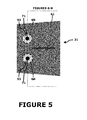
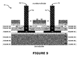
inboard region 21 of theelectrical mat 20 depicted inFigure 4 (shown enlarged inFigure 5 ) can have a cross-sectional construction as illustrated in any ofFigures 6-9 . In these constructions, eachbus 52 includes aconnection face 53 for electrical connection to theconnection face 36 of the lead line'sterminal 32. The term "connection face" refers to a site on the topology of abus 52, rather than a distinct segment or part. In most cases, there will be no structural distinction between theface 53 and the rest of thebus 52, other than the location of this site. - A
window 60 is associated with eachbus 52 and aligned with itsconnection face 53. Eachwindow 60 reaches through the thickness of thenonbondside layer 41 and any other layer (e.g., the adhesive film layer 42) located nonbondside of theheater layer 43. As is explained in more detail below, thewindow 60 preferably exists prior to layer lamination, to avoid post-lamination steps involving material removal near thebusses 52. - A
fastener 70 is adapted to mechanically attach thelead line 30 to theelectrical mat 20 in such a manner that itsconnection face 36 is electrically connected to the bus'sconnection face 53. Thefastener 70 hasstem 71 which extends through thewindow 60 and hasexternal threads 72. The cross-sectional size of thestem 71 is such there is agenerous gap 61 between it and window-defining edges. If thewindow 60 is circular, for example, thegap 61 will have annulus-like shape. - The
fastener 70 can have ahead 73 on the bondside end of itsstem 73. Thehead 73 is intended to sit substantially flush against one of thelayers 40, whereby can preferably be made as thin as possible (e.g., less than 1.0mm, less than 0.5mm, and/or less than 0.35mm). Additionally or alternatively, thehead 73 can have polygonal shape (e.g., hexagonal) so as to not encourage rotation relative to adjacent layers. - The fastener stem 71 preferably has a standard construction while the
fastener head 73 optimally has a much thinner than standard construction. Accordingly, one option for fastener fabrication is to modify the head of a standard fastener, filing it down to the desired thickness. In the embodiments illustrated inFigures 4-10 , thefastener 70 can comprise an off-the-shelf screw, a modified off-the-shelf screw, or a custom-machined component. - In the
inboard region 21 shown inFigure 6 , the fastener heads 73 are situated bondside of thelayer 48. The layers 43-48 have stem-receiving openings 143-148 aligned with eachwindow 60, with theopening 143 being located centrally within theconnection face 53 of the correspondingbus 52. Thestem 71 of eachfastener 70 extends, in the nonbondside direction, through the alignedwindow 60 and through the aligned fastener-receiving openings 143-148. In theinboard region 21 shown inFigure 7 , the fastener heads 73 are situated bondside of thelayer 47, and the fastener stems 71 extend throughwindows 60 and then through stem-receiving openings 143-147. In theinboard region 21 shown inFigure 8 , theheads 73 are situated bondside of thelayer 46 and the stems 71 extend throughwindows 60 and through openings 143-146. And in theinboard region 21 shown inFigure 9 , theheads 73 are situated bondside of theheater support layer 44, and the stems 71 extend through thewindows 60 and throughopenings 144. - The lead lines 30 are shown electrically connected to the
inboard regions 21 inFigures 10-15 . The lead lines 30 are electrically connected via astandard nut 74 havinginterior threads 75. The nuts 74 can be off-the-shelf items and they can be tightened onto the fastener'sstem 71 with a standard tool (e.g., a wrench). Thus, electrical connection can be accomplished with standard tools which do not require special skills and/or which consistently perform regardless of worker experience. And heat application on or near thebusses 52 is not required, thereby eliminating the risk of thermal damage thereto - Some method steps for making the
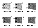
electrical mat 20 are shown schematically inFigures 16-37 . Specifically, for example, theheater layer 43 can be subassembled on thesupport layer 44 so that theconductive path 51 and thebusses 52 reside thereon (Figure 16 ). Stem-receiving openings 143-144 can be produced on the subassembled heater layers 43-44 (Figure 17 ). And thewindows 60 can created on the layers 41-42 nonbondside of the heater layer 43 (Figure 18 ). - For the
inboard region 21 shown inFigure 6 , the stem-receiving openings 145-148 are produced in the layers 45-48 (Figure 19 ), the layers 41-48 are compiled on abuild metal 81 with thefastener head 73 positioned below bondside layers 48 (Figure 20 ). Aplug 82 is preferably inserted into thewindow 60 so as to preserve its dimensions (Figure 21 ). The laminate can then be vacuum bagged and cured in a conventional manner. Although not specifically shown in the drawings, the laminate may be sandwiched between peel plies and/or release plies. - A similar approach is followed for the
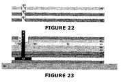
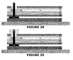
inboard region 21 shown inFigure 7 (Figures 22-24 ) and theinboard region 21 shown inFigure 8 (Figures 25-27 ). For theinboard region 21 shown inFigure 9 (Figures 28-29 ), opening-producing steps for layers bondside of theheater support layer 44 are not necessary. - For the
inboard region 21 shown inFigure 6 , the layers 41-48 can instead be compiled on thebuild metal 81 without the fasteners 70 (Figure 30 ), the stem-receiving openings 145-148 filled with a plug 83 (Figure 31 ), and thefasteners 70 inserted after curing and removal of the plugs 82-83 (Figure 32-33 ). Alternatively, the layers 41-48 can be compiled on thebuild metal 81 and cured without openings 145-148 (Figure 34 ), the stem-receiving openings 145-148 produced in a post-curing step (Figure 35 , and thefasteners 70 then inserted therethrough (Figure 36-37 ). - Another
electrical mat 20 andinboard region 21 is shown inFigures 38-43 . In this embodiment, the fastener heads 73 are situated nonbondside of theheater layer 43 and mounted on abus connection face 53 with a patch of electricallyconductive adhesive 76. The lead lines 30 can again be mechanically attached to thestem 71 via anut 74 havinginternal threads 75. - As shown in
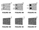
Figures 44-50 , themat 20 depicted inFigures 38-43 can be made in the same manner as discussed above, absent the opening-producing steps and with the addition of patch-applying step. Specifically, for example, theheater layer 43 can be subassembled on the support layer 44 (Figure 44 ) and thewindows 60 can created on the layers 41-42 nonbondside of the heater layer 43 (Figure 45 ). The layers 43-48 are then compiled on the build metal 81 (Figure 46 ), theadhesive patches 76 are placed on the busses' connection faces 53 (Figure 47 ) and the fastener heads 73 are secured to the patches 76 (Figure 48 ). The layers 41-42 are then compiled with the layers 43-48, with the fastener stems 71 extending through windows 60 (Figure 49 ). Aplug 82 is inserted into the window to preserve its dimensions (Figure 50 ) and then the laminate can then vacuum bagged and cured in a conventional manner. - Another
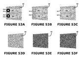
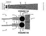
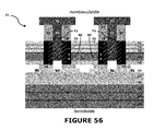
electrical mat 20 andinboard region 21 is shown inFigures 51-56 . In this embodiment, the fastener nut 74 (with internal threads) is mounted on abus connection face 53 with a patch of electricallyconductive adhesive 76. The lead lines 30 can be mechanically attached to thenut 74 via astem 72 havinginternal threads 73. As shown inFigures 57-64 , themat 20 can be made in the same manner as one discussed immediately above with the adhesively-attachedhead 73. However, additional laminate layers 91-93 may be necessary in theinboard region 21 to avoid over-protrusion of the nuts 74. And in this embodiment, aplug 84 can be positioned to preserve the nut'sinternal threads 75, rather than window dimensions. - With each of the connections shown in
Figures 10-15 , theconnection face 36 of thelead line 30 contacts the bus'sconnection face 53 to thereby directly establish electrical connection therewith. Thefastener stem 71 does not participate in the electrical connection path, but instead merely mechanically holds thelead line 30 so that itsconnection face 36 contacts thebus connection face 53. Thefastener head 73 and the fastener's nut 94 also do not participate in the electrical connection path in these embodiments. - With the connections shown in
Figures 41-43 and inFigures 54-56 , theconnection face 36 of thelead line 30 makes contact with thehead 73 or thenut 74 of thefastener 70. Electrical connection with the bus'sconnection face 53 is made indirectly through theadhesive patch 76. Thefastener stem 71 does not participate electrically in the electrical connection, but again merely mechanically holds thelead line 30 so that itsconnection face 36 contacts thebus connection face 53. In these embodiments, however, either thefastener head 73 or thefastener nut 74 participates electrically in the electrical connection of thelead line 30 to thebus 52. - In the
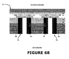
electrical mats 20 shown inFigures 4-9 ,Figure 40 , andFigure 53 , the electrical connections are made nonbondside. However, as shown inFigures 65-68 , the electrical connections could instead be made bondside. - In the
inboard regions 21 shown in the drawings, bothfasteners 70 are positioned in the same manner for the twobusses 52, but this need not be the case. Aninboard region 21 havingfasteners 70 positioned at different layer levels is feasible and foreseeable. Such a staggered positioning may be beneficial when theheater 50 has multiple conductive paths 51 (and thus multiple bus pairs). It may also help promote consistent thicknesses across theinboard region 21. Andelectrical mats 20 with both nonbondside and bondside electrical connections are certainly plausible and possible. - Accordingly, the aircraft
electrical mat 20 allows the heater'sbusses 52 to be electrically connected to the lead lines 30 with simple and standard fastening tools. These electrical connections can be accomplished without heat application near thebusses 52 and/or without post-lamination material removal steps. - As shown in
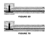
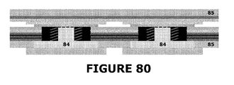
Figures 69-80 , the aircraftelectrical mat 10 can be delivered to the customer (e.g., an aircraft manufacturer), wrapped in instructional peel plies 85, with the dimension-preservingplug 82 still in thewindow 60, with the plug 83 still within the stem-receiving openings, and/or with theplug 84 still within the nuts 74. - While the
aircraft 10, theelectrical mat 20, the lead lines 30, the layers 41-48, theheater 50, thewindows 60, and/or thefasteners 70 have been shown and described with respect to certain embodiments, other equivalent alterations and modifications will occur to others skilled in the art upon the reading and understanding of this disclosure. For example, while theelectrical mats 20 are shown in connection withrotary helicopter blades 11, they can instead be installed on other rotary or non-rotary aircraft surfaces 12 susceptible to excessive ice accumulation. Furthermore, theelectrical mat 20 may also find application in non-aircraft situations such as, for example, wind turbine blades. - Moreover, the
mat 20 need not be for ice protection purposes, and/or theelement 50 need not be a heater element. In an aircraft setting, for example, theelectrical element 50 could be associated with lightning-strike protection with the lead lines 30 connected to ground. Theelement 50 can be any electrical element having abus 52 for electrical connection to alead line 30. -
REFERENCE NUMBERS 10 aircraft 47 bondside layer 11 aircraft components 48 bondside layer 12 ice- vulnerable surfaces 50 heater element 13 onboard power source 51 electrically conductive path 20 mat 52 bus 21 inboard region 53 connection face 30 lead lines 60 window 31 wire 61 stem-surrounding gap 32 ring terminal 70 fastener 33 crimp 71 stem 34 pedestal 72 external threads 35 ramp 73 head 36 bondside connection face 74 nut 37 nonbondside face 75 internal threads 41 nonbondside layer 76 electrically conductive adhesive 42 adhesive film layer 81 build metal 43 heater layer 82 window plug 44 heater-support layer 83 opening plug 45 adhesive film layer 84 nut plug 46 bondside layer 85 instructional peel plies 91 lofting layer 143 stem-receiving opening 92 lofting layer 144 stem-receiving opening 93 lofting layer 145 stem-receiving opening 134 stem-receiving opening 146 stem-receiving opening 141 stem-receiving opening 147 stem-receiving opening 142 stem-receiving opening 148 stem-receiving opening
Claims (15)
- An electrical mat (20) comprising a plurality of layers (41-48) including an electrical layer (43), an electrical element (50) on the layer (43) including at least one bus (52), a window (60) for each bus (52), and a fastener (70) for each window (60); wherein:each bus (52) has a connection face (53) for electrical connection to a lead line (30),each window (60) is aligned with the connection site (53) on the corresponding bus (52),each fastener (70) has a threaded part (71, 74) that extends through the corresponding window (60), andthe threaded part (71, 74) is adapted to mechanically attach a terminal (32) of the lead line (30) so as to establish an electrical connection between a connection face (36) of the lead line (30) and the connection face (53) of the corresponding bus (52).
- An electrical mat (20) as set forth in claim 1, wherein the electrical element (50) comprises at least one electrically conductive path (51) and a bus (52) is connected to each end of this path (51).
- An electrical mat (20) as set forth in claim 2, wherein the electrical element (50) is a heater element and the conductive path (51) has a resistance corresponding to a desired heat output.
- An electrical mat (20) as set forth in any preceding claim, wherein the window (60) reaches through the thickness of layers (41, 42) located nonbondside of the electrical layer (43).
- An electrical mat (20) as set forth in any of claims 1 to 3, wherein the window (60) reaches through the thickness of layers (41, 42) located bondside of the electrical layer (43).
- An electrical mat (20) as set forth in any preceding claim, wherein the fastener part is a stem (71) having external threads (72).
- An electrical mat (20) as set forth in any preceding claim, wherein the fastener (70) comprises a head (73) attached to the stem (71), wherein the head (73) of each fastener (70) optionally has a thickness less than 1.0mm, less than 0.50mm, and/or less than 0.35mm.
- An electrical mat (20) as set forth in claim 6 or 7, wherein each stem (71) extends through an opening (143) in the corresponding bus (52).
- An electrical mat (20) as set forth in claim 8, wherein the connection face (53) for each bus (52) surrounds the opening (143).
- An electrical mat (20) as set forth in claim 9, wherein the head (73) of each fastener (70) is mounted on the connection face (53) of the corresponding bus (52).
- An electrical mat (20) as set forth in claim 10, wherein the head (73) is secured to the connection face (53) with electrically conductive adhesive (76).
- An electrical mat (20) as set forth in any preceding claim, comprising a plug (82) in the window (60).
- An electrical mat (20) as set forth in any preceding claim, further comprising:a lead line (30) having a connection face (36) for each bus (52);wherein the fastener part (71, 74) mechanically attaches the lead line (30) to thereby establish an electrical connection between the connection face (36) of the lead line (30) and the connection face (53) of the bus (52).
- An aircraft (10) comprising:an onboard power source (13);an electrical mat (20) as set forth in any preceding claim; andlead lines (30) electrically connecting the electrical element (50) of the electrical mat (20) to the onboard power source (13).
- An aircraft (10) as set forth in claim 14, comprising a surface (12) and wherein the electrical mat (20) is installed on the surface (12), wherein, for example, the surface (12) is an ice-vulnerable surface and the electrical mat (20) is an ice protection mat.
Applications Claiming Priority (2)
| Application Number | Priority Date | Filing Date | Title |
|---|---|---|---|
| US201261678025P | 2012-07-31 | 2012-07-31 | |
| US201361766264P | 2013-02-19 | 2013-02-19 |
Publications (2)
| Publication Number | Publication Date |
|---|---|
| EP2692641A2 true EP2692641A2 (en) | 2014-02-05 |
| EP2692641A3 EP2692641A3 (en) | 2018-01-31 |
Family
ID=48914112
Family Applications (1)
| Application Number | Title | Priority Date | Filing Date |
|---|---|---|---|
| EP13178840.8A Withdrawn EP2692641A3 (en) | 2012-07-31 | 2013-07-31 | Aircraft electrical mat with solderless lead line connections |
Country Status (5)
| Country | Link |
|---|---|
| US (1) | US20140034783A1 (en) |
| EP (1) | EP2692641A3 (en) |
| CN (1) | CN103569365B (en) |
| BR (1) | BR102013019561A2 (en) |
| CA (1) | CA2822627A1 (en) |
Families Citing this family (2)
| Publication number | Priority date | Publication date | Assignee | Title |
|---|---|---|---|---|
| US11438973B2 (en) * | 2014-04-10 | 2022-09-06 | Metis Design Corporation | Multifunctional assemblies |
| EP3538440B1 (en) * | 2016-11-11 | 2020-07-15 | Bombardier Inc. | Signal return network for composite aircraft |
Family Cites Families (11)
| Publication number | Priority date | Publication date | Assignee | Title |
|---|---|---|---|---|
| FR897724A (en) * | 1942-12-02 | 1945-03-29 | Messerschmitt Ag | Device for connecting heating elements for aircraft de-icing |
| US2791668A (en) * | 1951-08-21 | 1957-05-07 | Napier & Son Ltd | Electrically heated de-icing or antifreezing apparatus |
| US3063031A (en) * | 1959-12-28 | 1962-11-06 | Gen Motors Corp | Electrical aircraft heater |
| US3217139A (en) * | 1961-04-19 | 1965-11-09 | Radcor Inc | Infrared heating assembly |
| US3146340A (en) * | 1961-08-21 | 1964-08-25 | Baird Atomic Inc | Heating devices |
| US3218436A (en) * | 1963-03-12 | 1965-11-16 | Gen Motors Corp | Electrical aircraft heater |
| JP2816800B2 (en) * | 1993-08-18 | 1998-10-27 | 第一電装部品株式会社 | Conductive connection device |
| JPH0982079A (en) * | 1995-07-10 | 1997-03-28 | Fujitsu Ltd | Optical storage |
| US7622695B2 (en) * | 2004-11-04 | 2009-11-24 | Dipucchio Jay | Multi-layered carrier |
| US7157663B1 (en) * | 2005-10-12 | 2007-01-02 | The Boeing Company | Conducting-fiber deicing systems and methods |
| WO2011127995A1 (en) * | 2010-04-12 | 2011-10-20 | Siemens Aktiengesellschaft | Fixation of a heating mat to a blade of a wind turbine |
-
2013
- 2013-07-30 CA CA2822627A patent/CA2822627A1/en not_active Abandoned
- 2013-07-31 US US13/955,712 patent/US20140034783A1/en not_active Abandoned
- 2013-07-31 BR BR102013019561A patent/BR102013019561A2/en not_active Application Discontinuation
- 2013-07-31 EP EP13178840.8A patent/EP2692641A3/en not_active Withdrawn
- 2013-07-31 CN CN201310414953.8A patent/CN103569365B/en not_active Expired - Fee Related
Non-Patent Citations (1)
| Title |
|---|
| None |
Also Published As
| Publication number | Publication date |
|---|---|
| CN103569365B (en) | 2017-06-06 |
| CN103569365A (en) | 2014-02-12 |
| CA2822627A1 (en) | 2014-01-31 |
| BR102013019561A2 (en) | 2015-09-22 |
| US20140034783A1 (en) | 2014-02-06 |
| EP2692641A3 (en) | 2018-01-31 |
Similar Documents
| Publication | Publication Date | Title |
|---|---|---|
| US6611659B2 (en) | Electrically heated aircraft composite floor panel | |
| US11597524B2 (en) | Heating device and method for manufacturing same | |
| EP2754891B1 (en) | Wind turbine rotor blade de-icing arrangement | |
| JP2017071388A (en) | A method for diverting lightning currents from the skin fasteners of composite non-metallic structures. | |
| DE19918736C2 (en) | Panel component, in particular for a floor panel in an aircraft | |
| EP2113456B1 (en) | Aircraft heated floor panel | |
| EP2650219B1 (en) | Deicer zones with heating-enhanced borders | |
| CN1141616A (en) | Variable watt density heating using stranded resistance wire | |
| EP3569496B1 (en) | Heated aircraft floor panels | |
| CA2819942A1 (en) | Aircraft ice protection system and method | |
| EP2390182B1 (en) | Aircraft heating system | |
| EP3248867B1 (en) | Propeller blade sheath | |
| WO2009153452A3 (en) | System for dissipating a lightning current generated by a thunderstorm discharge on an aircraft | |
| CN101978558A (en) | Connector and electrical tracks assembly | |
| WO2018095649A1 (en) | Blade for a wind turbine and connection arrangement | |
| EP2868575B1 (en) | Rotor blade with electrical interconnects | |
| US20140034783A1 (en) | Aircraft electrical mat with solderless lead line connections | |
| KR100847060B1 (en) | Flexible heating pad | |
| IL271605A (en) | Suppression of electrostatic discharge noise by means of conduction between a tiered metal element and the wiring system of a glazing unit | |
| US10066608B2 (en) | Method for repairing an electrical heating element of a wind turbine rotor blade | |
| JP2015109142A (en) | Polymer type lightning arrester and manufacturing method thereof | |
| EP3821123B1 (en) | Improvements relating to wind turbine blades | |
| EP4055235B1 (en) | A method for producing a heat module | |
| US11591959B2 (en) | Generator air gap heater | |
| EP3938715B1 (en) | Heating mat for use in a floor structure, floor structure, and method for producing same |
Legal Events
| Date | Code | Title | Description |
|---|---|---|---|
| AK | Designated contracting states |
Kind code of ref document: A2 Designated state(s): AL AT BE BG CH CY CZ DE DK EE ES FI FR GB GR HR HU IE IS IT LI LT LU LV MC MK MT NL NO PL PT RO RS SE SI SK SM TR |
|
| AX | Request for extension of the european patent |
Extension state: BA ME |
|
| PUAI | Public reference made under article 153(3) epc to a published international application that has entered the european phase |
Free format text: ORIGINAL CODE: 0009012 |
|
| PUAL | Search report despatched |
Free format text: ORIGINAL CODE: 0009013 |
|
| AK | Designated contracting states |
Kind code of ref document: A3 Designated state(s): AL AT BE BG CH CY CZ DE DK EE ES FI FR GB GR HR HU IE IS IT LI LT LU LV MC MK MT NL NO PL PT RO RS SE SI SK SM TR |
|
| AX | Request for extension of the european patent |
Extension state: BA ME |
|
| RIC1 | Information provided on ipc code assigned before grant |
Ipc: B64D 15/12 20060101AFI20171222BHEP |
|
| STAA | Information on the status of an ep patent application or granted ep patent |
Free format text: STATUS: THE APPLICATION HAS BEEN PUBLISHED |
|
| STAA | Information on the status of an ep patent application or granted ep patent |
Free format text: STATUS: THE APPLICATION IS DEEMED TO BE WITHDRAWN |
|
| 18D | Application deemed to be withdrawn |
Effective date: 20180801 |