EP2692551A1 - Bonding to a pneumatic tire - Google Patents
Bonding to a pneumatic tire Download PDFInfo
- Publication number
- EP2692551A1 EP2692551A1 EP13178354.0A EP13178354A EP2692551A1 EP 2692551 A1 EP2692551 A1 EP 2692551A1 EP 13178354 A EP13178354 A EP 13178354A EP 2692551 A1 EP2692551 A1 EP 2692551A1
- Authority
- EP
- European Patent Office
- Prior art keywords
- tire
- sidewall
- groove
- segment
- tube
- Prior art date
- Legal status (The legal status is an assumption and is not a legal conclusion. Google has not performed a legal analysis and makes no representation as to the accuracy of the status listed.)
- Withdrawn
Links
- 238000005452 bending Methods 0.000 claims abstract description 21
- 239000012815 thermoplastic material Substances 0.000 claims abstract description 19
- 238000005096 rolling process Methods 0.000 claims abstract description 13
- 230000004044 response Effects 0.000 claims abstract description 8
- 239000011324 bead Substances 0.000 claims abstract description 5
- 229920001169 thermoplastic Polymers 0.000 claims description 16
- 239000004416 thermosoftening plastic Substances 0.000 claims description 16
- 239000000853 adhesive Substances 0.000 claims description 15
- 230000001070 adhesive effect Effects 0.000 claims description 15
- -1 polyethylene Polymers 0.000 claims description 14
- 239000004699 Ultra-high molecular weight polyethylene Substances 0.000 claims description 9
- 229920000785 ultra high molecular weight polyethylene Polymers 0.000 claims description 9
- 239000004698 Polyethylene Substances 0.000 claims description 5
- 238000000034 method Methods 0.000 claims description 5
- 229920000573 polyethylene Polymers 0.000 claims description 5
- 239000004593 Epoxy Substances 0.000 claims description 4
- 239000004952 Polyamide Substances 0.000 claims description 4
- 239000004954 Polyphthalamide Substances 0.000 claims description 4
- 229920002647 polyamide Polymers 0.000 claims description 4
- 229920001955 polyphenylene ether Polymers 0.000 claims description 4
- 229920006375 polyphtalamide Polymers 0.000 claims description 4
- 239000004743 Polypropylene Substances 0.000 claims description 3
- 229920000728 polyester Polymers 0.000 claims description 3
- 229920001155 polypropylene Polymers 0.000 claims description 3
- 238000004519 manufacturing process Methods 0.000 claims 1
- 229920001971 elastomer Polymers 0.000 description 24
- 239000005060 rubber Substances 0.000 description 20
- KAKZBPTYRLMSJV-UHFFFAOYSA-N Butadiene Chemical compound C=CC=C KAKZBPTYRLMSJV-UHFFFAOYSA-N 0.000 description 12
- PPBRXRYQALVLMV-UHFFFAOYSA-N Styrene Chemical compound C=CC1=CC=CC=C1 PPBRXRYQALVLMV-UHFFFAOYSA-N 0.000 description 12
- 230000002572 peristaltic effect Effects 0.000 description 10
- 230000006835 compression Effects 0.000 description 7
- 238000007906 compression Methods 0.000 description 7
- 238000005086 pumping Methods 0.000 description 7
- 239000000463 material Substances 0.000 description 6
- 238000003780 insertion Methods 0.000 description 5
- 230000037431 insertion Effects 0.000 description 5
- 229920002857 polybutadiene Polymers 0.000 description 5
- RRHGJUQNOFWUDK-UHFFFAOYSA-N Isoprene Chemical compound CC(=C)C=C RRHGJUQNOFWUDK-UHFFFAOYSA-N 0.000 description 4
- 239000005062 Polybutadiene Substances 0.000 description 4
- 239000000806 elastomer Substances 0.000 description 4
- 238000012423 maintenance Methods 0.000 description 4
- 239000000654 additive Substances 0.000 description 3
- 229920001577 copolymer Polymers 0.000 description 3
- 238000007720 emulsion polymerization reaction Methods 0.000 description 3
- HQQADJVZYDDRJT-UHFFFAOYSA-N ethene;prop-1-ene Chemical group C=C.CC=C HQQADJVZYDDRJT-UHFFFAOYSA-N 0.000 description 3
- 238000002844 melting Methods 0.000 description 3
- 230000008018 melting Effects 0.000 description 3
- 239000000178 monomer Substances 0.000 description 3
- 229920000642 polymer Polymers 0.000 description 3
- 230000009467 reduction Effects 0.000 description 3
- ZGHFDIIVVIFNPS-UHFFFAOYSA-N 3-Methyl-3-buten-2-one Chemical compound CC(=C)C(C)=O ZGHFDIIVVIFNPS-UHFFFAOYSA-N 0.000 description 2
- HGINCPLSRVDWNT-UHFFFAOYSA-N Acrolein Chemical compound C=CC=O HGINCPLSRVDWNT-UHFFFAOYSA-N 0.000 description 2
- NLHHRLWOUZZQLW-UHFFFAOYSA-N Acrylonitrile Chemical compound C=CC#N NLHHRLWOUZZQLW-UHFFFAOYSA-N 0.000 description 2
- NINIDFKCEFEMDL-UHFFFAOYSA-N Sulfur Chemical compound [S] NINIDFKCEFEMDL-UHFFFAOYSA-N 0.000 description 2
- XLOMVQKBTHCTTD-UHFFFAOYSA-N Zinc monoxide Chemical compound [Zn]=O XLOMVQKBTHCTTD-UHFFFAOYSA-N 0.000 description 2
- RTACIUYXLGWTAE-UHFFFAOYSA-N buta-1,3-diene;2-methylbuta-1,3-diene;styrene Chemical compound C=CC=C.CC(=C)C=C.C=CC1=CC=CC=C1 RTACIUYXLGWTAE-UHFFFAOYSA-N 0.000 description 2
- MTAZNLWOLGHBHU-UHFFFAOYSA-N butadiene-styrene rubber Chemical compound C=CC=C.C=CC1=CC=CC=C1 MTAZNLWOLGHBHU-UHFFFAOYSA-N 0.000 description 2
- 229920005549 butyl rubber Polymers 0.000 description 2
- 230000001413 cellular effect Effects 0.000 description 2
- 229920003193 cis-1,4-polybutadiene polymer Polymers 0.000 description 2
- 229920003211 cis-1,4-polyisoprene Polymers 0.000 description 2
- 238000004140 cleaning Methods 0.000 description 2
- 230000000295 complement effect Effects 0.000 description 2
- 150000001875 compounds Chemical class 0.000 description 2
- 230000001419 dependent effect Effects 0.000 description 2
- 150000001993 dienes Chemical class 0.000 description 2
- FJKIXWOMBXYWOQ-UHFFFAOYSA-N ethenoxyethane Chemical compound CCOC=C FJKIXWOMBXYWOQ-UHFFFAOYSA-N 0.000 description 2
- 239000000203 mixture Substances 0.000 description 2
- 238000012544 monitoring process Methods 0.000 description 2
- 229920001084 poly(chloroprene) Polymers 0.000 description 2
- 229920001707 polybutylene terephthalate Polymers 0.000 description 2
- 229920000139 polyethylene terephthalate Polymers 0.000 description 2
- 239000005020 polyethylene terephthalate Substances 0.000 description 2
- 229920001195 polyisoprene Polymers 0.000 description 2
- 229920005989 resin Polymers 0.000 description 2
- 239000011347 resin Substances 0.000 description 2
- 229910052717 sulfur Inorganic materials 0.000 description 2
- 239000011593 sulfur Substances 0.000 description 2
- 229920003051 synthetic elastomer Polymers 0.000 description 2
- 239000005061 synthetic rubber Substances 0.000 description 2
- 229920001897 terpolymer Polymers 0.000 description 2
- 125000000391 vinyl group Chemical group [H]C([*])=C([H])[H] 0.000 description 2
- PMJHHCWVYXUKFD-SNAWJCMRSA-N (E)-1,3-pentadiene Chemical compound C\C=C\C=C PMJHHCWVYXUKFD-SNAWJCMRSA-N 0.000 description 1
- HECLRDQVFMWTQS-RGOKHQFPSA-N 1755-01-7 Chemical compound C1[C@H]2[C@@H]3CC=C[C@@H]3[C@@H]1C=C2 HECLRDQVFMWTQS-RGOKHQFPSA-N 0.000 description 1
- SDJHPPZKZZWAKF-UHFFFAOYSA-N 2,3-dimethylbuta-1,3-diene Chemical compound CC(=C)C(C)=C SDJHPPZKZZWAKF-UHFFFAOYSA-N 0.000 description 1
- SMZOUWXMTYCWNB-UHFFFAOYSA-N 2-(2-methoxy-5-methylphenyl)ethanamine Chemical compound COC1=CC=C(C)C=C1CCN SMZOUWXMTYCWNB-UHFFFAOYSA-N 0.000 description 1
- NIXOWILDQLNWCW-UHFFFAOYSA-N 2-Propenoic acid Natural products OC(=O)C=C NIXOWILDQLNWCW-UHFFFAOYSA-N 0.000 description 1
- 244000043261 Hevea brasiliensis Species 0.000 description 1
- VQTUBCCKSQIDNK-UHFFFAOYSA-N Isobutene Chemical group CC(C)=C VQTUBCCKSQIDNK-UHFFFAOYSA-N 0.000 description 1
- CERQOIWHTDAKMF-UHFFFAOYSA-N Methacrylic acid Chemical compound CC(=C)C(O)=O CERQOIWHTDAKMF-UHFFFAOYSA-N 0.000 description 1
- VVQNEPGJFQJSBK-UHFFFAOYSA-N Methyl methacrylate Chemical compound COC(=O)C(C)=C VVQNEPGJFQJSBK-UHFFFAOYSA-N 0.000 description 1
- 239000004677 Nylon Substances 0.000 description 1
- 229920002292 Nylon 6 Polymers 0.000 description 1
- 229920002302 Nylon 6,6 Polymers 0.000 description 1
- 229920005683 SIBR Polymers 0.000 description 1
- XUIMIQQOPSSXEZ-UHFFFAOYSA-N Silicon Chemical compound [Si] XUIMIQQOPSSXEZ-UHFFFAOYSA-N 0.000 description 1
- ATJFFYVFTNAWJD-UHFFFAOYSA-N Tin Chemical compound [Sn] ATJFFYVFTNAWJD-UHFFFAOYSA-N 0.000 description 1
- 229920010741 Ultra High Molecular Weight Polyethylene (UHMWPE) Polymers 0.000 description 1
- 230000009471 action Effects 0.000 description 1
- 239000012190 activator Substances 0.000 description 1
- 230000000996 additive effect Effects 0.000 description 1
- 150000001299 aldehydes Chemical class 0.000 description 1
- 150000001336 alkenes Chemical class 0.000 description 1
- 125000005370 alkoxysilyl group Chemical group 0.000 description 1
- 239000003963 antioxidant agent Substances 0.000 description 1
- 230000008901 benefit Effects 0.000 description 1
- 229920005557 bromobutyl Polymers 0.000 description 1
- WFYPICNXBKQZGB-UHFFFAOYSA-N butenyne Chemical group C=CC#C WFYPICNXBKQZGB-UHFFFAOYSA-N 0.000 description 1
- 239000003795 chemical substances by application Substances 0.000 description 1
- 229920005556 chlorobutyl Polymers 0.000 description 1
- 239000002131 composite material Substances 0.000 description 1
- 239000000470 constituent Substances 0.000 description 1
- 238000010276 construction Methods 0.000 description 1
- 230000008602 contraction Effects 0.000 description 1
- 230000008878 coupling Effects 0.000 description 1
- 238000010168 coupling process Methods 0.000 description 1
- 238000005859 coupling reaction Methods 0.000 description 1
- 230000006378 damage Effects 0.000 description 1
- 235000014113 dietary fatty acids Nutrition 0.000 description 1
- 238000009792 diffusion process Methods 0.000 description 1
- CJSBUWDGPXGFGA-UHFFFAOYSA-N dimethyl-butadiene Natural products CC(C)=CC=C CJSBUWDGPXGFGA-UHFFFAOYSA-N 0.000 description 1
- 239000000839 emulsion Substances 0.000 description 1
- 150000002170 ethers Chemical class 0.000 description 1
- 125000002534 ethynyl group Chemical class [H]C#C* 0.000 description 1
- 239000000194 fatty acid Substances 0.000 description 1
- 229930195729 fatty acid Natural products 0.000 description 1
- 150000004665 fatty acids Chemical class 0.000 description 1
- 239000000945 filler Substances 0.000 description 1
- 238000011010 flushing procedure Methods 0.000 description 1
- 238000010528 free radical solution polymerization reaction Methods 0.000 description 1
- 239000000446 fuel Substances 0.000 description 1
- 229920005555 halobutyl Polymers 0.000 description 1
- 125000004968 halobutyl group Chemical group 0.000 description 1
- 238000005304 joining Methods 0.000 description 1
- 150000002576 ketones Chemical class 0.000 description 1
- 239000004816 latex Substances 0.000 description 1
- 229920000126 latex Polymers 0.000 description 1
- 230000004048 modification Effects 0.000 description 1
- 238000012986 modification Methods 0.000 description 1
- 229920003052 natural elastomer Polymers 0.000 description 1
- 229920001194 natural rubber Polymers 0.000 description 1
- 229920001778 nylon Polymers 0.000 description 1
- 239000003921 oil Substances 0.000 description 1
- 239000002245 particle Substances 0.000 description 1
- 230000037361 pathway Effects 0.000 description 1
- PMJHHCWVYXUKFD-UHFFFAOYSA-N penta-1,3-diene Chemical compound CC=CC=C PMJHHCWVYXUKFD-UHFFFAOYSA-N 0.000 description 1
- 239000000049 pigment Substances 0.000 description 1
- 229920003023 plastic Polymers 0.000 description 1
- 239000004033 plastic Substances 0.000 description 1
- 239000004014 plasticizer Substances 0.000 description 1
- 230000000379 polymerizing effect Effects 0.000 description 1
- 229920000098 polyolefin Polymers 0.000 description 1
- 239000011148 porous material Substances 0.000 description 1
- 238000012545 processing Methods 0.000 description 1
- 230000000246 remedial effect Effects 0.000 description 1
- 238000010058 rubber compounding Methods 0.000 description 1
- 229910052710 silicon Inorganic materials 0.000 description 1
- 239000010703 silicon Substances 0.000 description 1
- 230000007480 spreading Effects 0.000 description 1
- 238000003892 spreading Methods 0.000 description 1
- 229920001059 synthetic polymer Polymers 0.000 description 1
- 229920001567 vinyl ester resin Polymers 0.000 description 1
- 239000001993 wax Substances 0.000 description 1
- 239000011787 zinc oxide Substances 0.000 description 1
Images












Classifications
-
- B—PERFORMING OPERATIONS; TRANSPORTING
- B29—WORKING OF PLASTICS; WORKING OF SUBSTANCES IN A PLASTIC STATE IN GENERAL
- B29D—PRODUCING PARTICULAR ARTICLES FROM PLASTICS OR FROM SUBSTANCES IN A PLASTIC STATE
- B29D30/00—Producing pneumatic or solid tyres or parts thereof
- B29D30/06—Pneumatic tyres or parts thereof (e.g. produced by casting, moulding, compression moulding, injection moulding, centrifugal casting)
- B29D30/0601—Vulcanising tyres; Vulcanising presses for tyres
- B29D30/0661—Rigid cores therefor, e.g. annular or substantially toroidal cores
-
- B—PERFORMING OPERATIONS; TRANSPORTING
- B60—VEHICLES IN GENERAL
- B60C—VEHICLE TYRES; TYRE INFLATION; TYRE CHANGING; CONNECTING VALVES TO INFLATABLE ELASTIC BODIES IN GENERAL; DEVICES OR ARRANGEMENTS RELATED TO TYRES
- B60C19/00—Tyre parts or constructions not otherwise provided for
-
- B—PERFORMING OPERATIONS; TRANSPORTING
- B29—WORKING OF PLASTICS; WORKING OF SUBSTANCES IN A PLASTIC STATE IN GENERAL
- B29D—PRODUCING PARTICULAR ARTICLES FROM PLASTICS OR FROM SUBSTANCES IN A PLASTIC STATE
- B29D30/00—Producing pneumatic or solid tyres or parts thereof
- B29D30/06—Pneumatic tyres or parts thereof (e.g. produced by casting, moulding, compression moulding, injection moulding, centrifugal casting)
- B29D30/72—Side-walls
-
- B—PERFORMING OPERATIONS; TRANSPORTING
- B60—VEHICLES IN GENERAL
- B60C—VEHICLE TYRES; TYRE INFLATION; TYRE CHANGING; CONNECTING VALVES TO INFLATABLE ELASTIC BODIES IN GENERAL; DEVICES OR ARRANGEMENTS RELATED TO TYRES
- B60C23/00—Devices for measuring, signalling, controlling, or distributing tyre pressure or temperature, specially adapted for mounting on vehicles; Arrangement of tyre inflating devices on vehicles, e.g. of pumps or of tanks; Tyre cooling arrangements
- B60C23/10—Arrangement of tyre-inflating pumps mounted on vehicles
- B60C23/12—Arrangement of tyre-inflating pumps mounted on vehicles operated by a running wheel
- B60C23/121—Arrangement of tyre-inflating pumps mounted on vehicles operated by a running wheel the pumps being mounted on the tyres
- B60C23/123—Elongate peristaltic pumps
-
- B—PERFORMING OPERATIONS; TRANSPORTING
- B60—VEHICLES IN GENERAL
- B60C—VEHICLE TYRES; TYRE INFLATION; TYRE CHANGING; CONNECTING VALVES TO INFLATABLE ELASTIC BODIES IN GENERAL; DEVICES OR ARRANGEMENTS RELATED TO TYRES
- B60C23/00—Devices for measuring, signalling, controlling, or distributing tyre pressure or temperature, specially adapted for mounting on vehicles; Arrangement of tyre inflating devices on vehicles, e.g. of pumps or of tanks; Tyre cooling arrangements
- B60C23/10—Arrangement of tyre-inflating pumps mounted on vehicles
- B60C23/12—Arrangement of tyre-inflating pumps mounted on vehicles operated by a running wheel
- B60C23/135—Arrangement of tyre-inflating pumps mounted on vehicles operated by a running wheel activated due to tyre deformation
-
- B—PERFORMING OPERATIONS; TRANSPORTING
- B29—WORKING OF PLASTICS; WORKING OF SUBSTANCES IN A PLASTIC STATE IN GENERAL
- B29D—PRODUCING PARTICULAR ARTICLES FROM PLASTICS OR FROM SUBSTANCES IN A PLASTIC STATE
- B29D30/00—Producing pneumatic or solid tyres or parts thereof
- B29D30/06—Pneumatic tyres or parts thereof (e.g. produced by casting, moulding, compression moulding, injection moulding, centrifugal casting)
- B29D30/48—Bead-rings or bead-cores; Treatment thereof prior to building the tyre
- B29D2030/483—Treating the bead cores to increase rubber adhesion
-
- B—PERFORMING OPERATIONS; TRANSPORTING
- B29—WORKING OF PLASTICS; WORKING OF SUBSTANCES IN A PLASTIC STATE IN GENERAL
- B29D—PRODUCING PARTICULAR ARTICLES FROM PLASTICS OR FROM SUBSTANCES IN A PLASTIC STATE
- B29D30/00—Producing pneumatic or solid tyres or parts thereof
- B29D30/06—Pneumatic tyres or parts thereof (e.g. produced by casting, moulding, compression moulding, injection moulding, centrifugal casting)
- B29D30/72—Side-walls
- B29D2030/724—Stiffening the sidewalls, e.g. by using additional inserts, e.g. made of rubber, plastics or other materials
-
- B—PERFORMING OPERATIONS; TRANSPORTING
- B29—WORKING OF PLASTICS; WORKING OF SUBSTANCES IN A PLASTIC STATE IN GENERAL
- B29K—INDEXING SCHEME ASSOCIATED WITH SUBCLASSES B29B, B29C OR B29D, RELATING TO MOULDING MATERIALS OR TO MATERIALS FOR MOULDS, REINFORCEMENTS, FILLERS OR PREFORMED PARTS, e.g. INSERTS
- B29K2223/00—Use of polyalkenes or derivatives thereof as reinforcement
- B29K2223/04—Polymers of ethylene
- B29K2223/06—PE, i.e. polyethylene
-
- B—PERFORMING OPERATIONS; TRANSPORTING
- B29—WORKING OF PLASTICS; WORKING OF SUBSTANCES IN A PLASTIC STATE IN GENERAL
- B29K—INDEXING SCHEME ASSOCIATED WITH SUBCLASSES B29B, B29C OR B29D, RELATING TO MOULDING MATERIALS OR TO MATERIALS FOR MOULDS, REINFORCEMENTS, FILLERS OR PREFORMED PARTS, e.g. INSERTS
- B29K2223/00—Use of polyalkenes or derivatives thereof as reinforcement
- B29K2223/10—Polymers of propylene
- B29K2223/12—PP, i.e. polypropylene
-
- B—PERFORMING OPERATIONS; TRANSPORTING
- B29—WORKING OF PLASTICS; WORKING OF SUBSTANCES IN A PLASTIC STATE IN GENERAL
- B29K—INDEXING SCHEME ASSOCIATED WITH SUBCLASSES B29B, B29C OR B29D, RELATING TO MOULDING MATERIALS OR TO MATERIALS FOR MOULDS, REINFORCEMENTS, FILLERS OR PREFORMED PARTS, e.g. INSERTS
- B29K2267/00—Use of polyesters or derivatives thereof as reinforcement
-
- B—PERFORMING OPERATIONS; TRANSPORTING
- B29—WORKING OF PLASTICS; WORKING OF SUBSTANCES IN A PLASTIC STATE IN GENERAL
- B29K—INDEXING SCHEME ASSOCIATED WITH SUBCLASSES B29B, B29C OR B29D, RELATING TO MOULDING MATERIALS OR TO MATERIALS FOR MOULDS, REINFORCEMENTS, FILLERS OR PREFORMED PARTS, e.g. INSERTS
- B29K2271/00—Use of polyethers, e.g. PEEK, i.e. polyether-etherketone or PEK, i.e. polyetherketone or derivatives thereof, as reinforcement
- B29K2271/12—PPO, i.e. polyphenylene oxide; PPE, i.e. polyphenylene ether
-
- B—PERFORMING OPERATIONS; TRANSPORTING
- B29—WORKING OF PLASTICS; WORKING OF SUBSTANCES IN A PLASTIC STATE IN GENERAL
- B29K—INDEXING SCHEME ASSOCIATED WITH SUBCLASSES B29B, B29C OR B29D, RELATING TO MOULDING MATERIALS OR TO MATERIALS FOR MOULDS, REINFORCEMENTS, FILLERS OR PREFORMED PARTS, e.g. INSERTS
- B29K2277/00—Use of PA, i.e. polyamides, e.g. polyesteramides or derivatives thereof, as reinforcement
-
- Y—GENERAL TAGGING OF NEW TECHNOLOGICAL DEVELOPMENTS; GENERAL TAGGING OF CROSS-SECTIONAL TECHNOLOGIES SPANNING OVER SEVERAL SECTIONS OF THE IPC; TECHNICAL SUBJECTS COVERED BY FORMER USPC CROSS-REFERENCE ART COLLECTIONS [XRACs] AND DIGESTS
- Y10—TECHNICAL SUBJECTS COVERED BY FORMER USPC
- Y10T—TECHNICAL SUBJECTS COVERED BY FORMER US CLASSIFICATION
- Y10T152/00—Resilient tires and wheels
- Y10T152/10—Tires, resilient
- Y10T152/10495—Pneumatic tire or inner tube
Definitions
- the invention relates generally to bonding parts to a pneumatic tire and, more specifically, to bonding parts of a pumping assembly to a pneumatic tire.
- Tire Pressure Monitoring Systems have been proposed to warn drivers when tire pressure is significantly low. Such systems, however, remain dependent upon the driver taking remedial action when warned to re-inflate a tire to recommended pressure. It is a desirable, therefore, to incorporate an air maintenance feature within a tire that will maintain air pressure within the tire in order to compensate for any reduction in tire pressure over time without the need for driver intervention.
- the invention relates to a tire in accordance with claim 1 and to a method in accordance with claim 15.
- a pneumatic tire assembly may comprise: A tire having a pneumatic cavity; a rigid structure for facilitating operation of the tire assembly, the rigid structure being bonded to the tire by a layered thermoplastic material such that a stiffness gradient is created between the structure and the tire; first and second sidewalls extending respectively from first and second tire bead regions to a tire tread region, the first sidewall having at least one bending region operatively bending when radially within a rolling tire footprint; and a sidewall groove defined by groove walls positioned within the bending region of the first tire sidewall, the sidewall groove deforming segment by segment between a non-deformed state and a deformed, constricted state in response to bending of the bending region of the first sidewall while radially within the rolling tire footprint.
- An air passageway is defined by the sidewall groove and deforms segment by segment between an expanded condition and an at least partially collapsed condition in response to respective segment by segment deformation of the sidewall groove when radially within the rolling tire footprint.
- the thermoplastic material may be selected from the group consisting of polyethylene, polypropylene, polyamide, polyester, polyphenylene ether, and polyphthalamide.
- thermoplastic material may be polyethylene
- the rigid structure may further comprise an adhesive selected from the group consisting of an RFL adhesive and an epoxy-based adhesive.
- thermoplastic material may comprise a plurality of thermoplastic layers.
- the thermoplastic material may comprise a plurality of thermoplastic layers wherein the thermoplastic layers have a layer thickness ranging from 0.1 to 1 mm.
- thermoplastic material may comprise at least ten thermoplastic layers.
- the thermoplastic material may comprise a plurality of thermoplastic layers with an adhesive disposed between the thermoplastic layers.
- the thermoplastic material may comprise at least ten thermoplastic layers with an adhesive disposed between the thermoplastic layers.
- the rigid structure may be constructed of ultra high molecular weight polyethylene.
- the rigid structure and the tire may define a built-in tube-like cavity.
- the rigid structure and the tire preferably reroute pressurized air to a pump assembly, and from there, into the pneumatic cavity.
- a separate tube may be disposed within the sidewall groove, the separate tube defining a circular air passageway.
- the separate tube preferably has an outer profile corresponding to an inner profile of the sidewall groove.
- the rigid structure preferably comprises a plurality of check valves disposed at multiple arcuate positions about the sidewall groove.
- a subcoat may be applied to a bare surface of the rigid structure and a topcoat may be applied to the subcoat.
- the subcoat may be dried to the bare surface of the rigid structure for instance at 180C for 8 min.
- Axial and “axially” means lines or directions that are parallel to the axis of rotation of the tire.
- “Circumferential” means lines or directions extending along the perimeter of the surface of the annular tread perpendicular to the axial direction.
- Equatorial Centerplane means the plane perpendicular to the tire's axis of rotation and passing through the center of the tread.
- “Footprint” means the contact patch or area of contact of the tire tread with a flat surface at zero speed and under normal load and pressure.
- “Lateral” means an axial direction.
- Periodaltic means operating by means of wave-like contractions that propel contained matter, such as air, along tubular pathways.
- Ring and radially means directions radially toward or away from the axis of rotation of the tire.
- an example tire assembly 10 includes a tire 12, a peristaltic pump assembly 14, and a tire rim 16.
- the tire mounts in conventional fashion to a pair of rim mounting surfaces 18, 20 adjacent outer rim flanges 22, 24.
- the rim flanges 22, 24 each have a radially outward facing flange end 26.
- a rim body 28 may support the tire assembly 10 as shown.
- the tire 12 may be of conventional construction, having a pair of sidewalls 30, 32 extending from opposite bead areas 34, 36 to a crown or tire tread region 38.
- the tire 12 and rim 16 enclose a tire cavity 40.
- the example peristaltic pump assembly 14 includes an annular air tube 42 that encloses an annular passageway 43.
- the tube 42 is formed of a resilient, flexible material such as plastic or rubber compounds that are capable of withstanding repeated deformation cycles of a flattened condition subject to external force and, upon removal of such force, returned to an original condition generally circular in cross-section.
- the tube 42 has a diameter sufficient to operatively pass a volume of air for purposes described herein and allowing a positioning of the tube in an operable location within the tire assembly 10 as will be described below.
- the tube 42 may be an elongate, generally elliptical shape in cross-section, having opposite tube sidewalls 44, 46 extending from a flat (closed) trailing tube end 48 to a radiussed (open) leading tube end 50.
- the tube 42 may have a longitudinal outwardly projecting pair of locking detent ribs 52 of generally semi-circular cross-section and each rib extending along outward surfaces of the sidewalls 44, 46, respectively.
- the tube 42 may have a length L1 within a range of 3.65 mm to 3.80 mm; a width of D1 within a range of 2.2 mm to 3.8 mm; a trailing end width of D3 within a range of 0.8 mm to 1.0 mm.
- the protruding detent ribs 52, 54 may each have a radius of curvature R2 within a range of 0.2 mm to 0.5 mm and each rib may be located at a position distance L3 within a range of 1.8 mm to 2.0 mm of the trailing tube end 48.
- the leading end 50 of the tube 42 may have a radius R1 within a range of 1.1 mm to 1.9 mm.
- the air passageway 43 within the tube 42 may likewise be generally elliptical with a length L2 within a range of 2.2 mm to 2.3 mm; and a width D2 within a range of 0.5 mm to 0.9 mm.
- the tube 42 is profiled and geometrically configured for insertion into a groove 56.
- the groove 56 may have an elongate, generally elliptical configuration with a length L1 within a range of 3.65 mm to 3.80 mm complementary to the elliptical shape of the tube 42.
- the groove 56 may include a restricted narrower entryway 58 having a nominal cross-sectional width D3 within a range of 0.8 mm to 1.0 mm.
- a pair of groove-rib receiving axial detent channels 60, 62 of semi-circular configuration may be formed within opposite sides of the groove 56 for corresponding receipt of the tube locking ribs 52, 54, respectively.
- the channels 60, 62 may be spaced approximately a distance L3 within a range of 1.8 mm to 2.0 mm of the groove entryway 58.
- Detent channels 60, 62 may each have a radius of curvature R2 within a range of 0.2 mm to 0.5 mm.
- An inward detent groove portion 64 may be formed with a radius of curvature R1 within a range of 1.1 mm to 1.9 mm and a cross-sectional nominal width D1 within a range of 2.2 mm to 3.8 mm.
- the tire 12 may further form one or more compression ribs 66 extending the circumference of, and projecting into, the groove 56.
- the ribs 66 may form a pattern of ribs of prescribed pitch, frequency, and location, as described below.
- seven compression ribs may be referred to generally by numeral 66 in the first rib profile pattern shown, and specifically by the rib designations D0 through D6.
- the ribs D0 through D6 may be formed in a sequence and pitch pattern in order to optimize the pumping of air through the tube passageway 43.
- the ribs 66 may each have a unique and predetermined height and placement within the pattern and, as shown in FIG. 8D , project outward into the groove 56 at a radius R3 ( FIG. 8A ) within a range of 0.95 mm to 1.60 mm.
- the peristaltic pump assembly 14 further includes an inlet device 68 and an outlet device 70 preferable spaced apart approximately 180 degrees at respective locations along the circumferential air tube 42.
- the example outlet device 70 has a T-shaped configuration in which conduits 72, 74 direct air to, and from, the tire cavity 40.
- An outlet device housing 76 contains conduit arms 78, 80 that integrally extend from respective conduits 72, 74.
- Each of the conduit arms 78, 80 have external coupling ribs 82, 84 for retaining the conduits within disconnected ends of the air tube 42 in the assembled condition.
- the housing 76 is formed having an external geometry that complements the groove 56 and includes a flat end 86, a radiused generally oblong body 88, and outwardly projecting longitudinal detent ribs 90.
- the housing 76 may thus be capable of close receipt into the groove 56 at its intended location with the ribs 90 registering within the groove 56 as represented in FIG. 8A .
- the inlet device 68 may include an elongate outward sleeve body 94 joining an elongate inward sleeve body 96 at a narrow sleeve neck 98.
- the outward sleeve body is generally triangular in section.
- the inward sleeve body 96 has an oblong external geometry complementary to the groove 56 and includes a pair of detent ribs 100 extending longitudinally along the inward sleeve body.
- An elongate air entry tube 101 is positioned within the inward sleeve body 96 and includes opposite tube ends 102 and a pattern of entry apertures 104 extending into a central tube passageway. External ribs 106, 108 secure the tube ends 102 in the air tube 42 opposite the outlet device 70.
- the pump assembly 14 comprises the air tube 42 and inlet and outlet devices 68, 70 affixed in-line to the air tube at respective locations 180 degrees apart when inserted into the groove 56.
- the groove 56 may be located at a lower sidewall region of the tire 12 that, when the tire is mounted to the rim 16, positions the air tube 42 above the rim flange ends 26.
- FIG. 8B shows the air tube 42 diametrically squeezed and collapsed to accommodate insertion into the groove 56. Upon full insertion, as shown in FIG.
- the ribs 52, 54 may register within the groove channels 60, 62 and the flat outer end 48 of the tube 42 may be generally coplanar with the outer surface of the sidewall of the tire. Once fully inserted, the air passageway 43 of the tube 42 may elastically restore itself into an open condition to allow the flow of air along the tube during operation of the pump.
- the inlet device 68 and the outlet device 70 may be positioned within the circumference of the circular air tube 42 generally 180 degrees apart.
- the tire 12 with the tube 42 positioned within groove 56 rotates in a direction of rotation 110, causing a footprint 120 to be formed against the ground surface 118.
- a compressive force 124 is directed into the tire 12 from the footprint 120 and acts to flatten a segment of the air tube passageway 43 opposite the footprint 120, as shown at numeral 122. Flattening of a segment of the passageway 43 forces air from the segment along the tube passageway 43 in the direction shown by arrow 116, toward the outlet device 70.
- the tube 42 may be sequentially flattened or squeezed opposite the tire footprint, segment by segment, in a direction opposite to the direction 110.
- a sequential flattening of the tube passageway 43, segment by segment, may cause evacuated air from the flattened segments to be pumped in the direction 116 within tube passageway 43 toward the outlet device 70.
- Air may flow through the outlet device 70 and to the tire cavity 40, as shown at 130.
- air exiting the outlet device 70 may be routed to the tire cavity 40 and serve to re-inflate the tire 12 to a desired pressure level.
- a valve system to regulate the flow of air to the cavity 40, when the air pressure within the cavity falls to a prescribed level, is shown and described in pending US-A- 2011/0272073 incorporated herein by reference.
- FIG. 5A shows the orientation of the peristaltic pump assembly 14 in such a position.
- the tube 42 may continue to be sequentially flattened, segment by segment, opposite the tire footprint 120 by a compressive force 124. Air may be pumped in the clockwise direction 116 to the inlet device 68 and evacuated or exhausted external to the tire 12.
- Passage of exhaust air, as shown at 128, from the inlet device 68 may occur through a filter sleeve 92 exemplarily formed of a cellular or porous material or composite. Flow of air through the filter sleeve 92 and into the tube 101 may thus cleanse debris or particulates. In the exhaust or reverse flow of air direction 128, the filter sleeve 92 may be cleansed of trapped accumulated debris or particles within the porous medium.
- the outlet device 70 With the evacuation of pumped air out of the inlet device 68, the outlet device 70 may be in a closed position preventing air flow to the tire cavity 40.
- the airflow may resume to the outlet device and cause the pumped air to flow out and into the tire cavity 40. Air pressure within the tire cavity 40 may thus be maintained at a desired level.
- FIG. 5B illustrates that the tube 42 is flattened, segment by segment, as the tire 12 rotates in direction 110.
- a flattened segment 134 moves counterclockwise as it is rotated away from the tire footprint 120 while an adjacent segment 132 moves opposite the tire footprint and is flattened.
- the progression of squeezed or flattened or closed tube segments may be move air toward the outlet device 70 ( FIG. 5A ) or the inlet device 68 ( FIG. 5B ) depending on the rotational position of the tire 12 relative to such devices.
- the compression forces within the tire 12 from the footprint region may be eliminated and the segment may resiliently reconfigure into an unflattened or open condition as the segment refills with air from the passageway 43.
- FIGS. 6A and 6B show a segment of the tube 42 in the flattened condition while FIGS. 6A and 6B show the segment in an expanded, unflat or open configuration prior to, and after, moving away from a location opposite the tire footprint 120.
- segments of the tube 42 may resume the exemplary oblong generally elliptical shape.
- the above-described cycle may repeat for each tire revolution, with half of each rotation resulting in pumped air moving to the tire cavity 40 and half of each rotation resulting in pumped air moving back out the filter sleeve 92 of the inlet device 68 for self-cleaning the filter.
- the direction of rotation 110 of the tire 12 is as shown in FIGS. 5A and 5B is counterclockwise
- the subject tire assembly 10 and its peristaltic pump assembly 14 may function in a like manner in a reverse (clockwise) direction of rotation as well.
- the peristaltic pump assembly 14 may accordingly be bi-directional and equally functional with the tire 12 and vehicle moving in a forward or reverse direction of rotation and forward or reverse direction of the vehicle.
- the air tube/pump assembly 14 may be as shown in FIGS.5A , 5B , 6A , 6B , 7A and 7B .
- the tube 42 may be located within the groove 56 in a lower region of the sidewall 30 of the tire 12.
- the passageway 43 of the tube 42 may close by compression strain bending of the sidewall groove 56 within a rolling tire footprint 120, as explained above.
- the location of the tube 42 in the sidewall 30 may provide freedom of placement thereby avoiding contact between the tube 42 and the rim 16. Higher placement of the tube 42 in the sidewall groove 56 may use high deformation characteristics of this region of the sidewall as it passes through the tire footprint 120 to close the tube 42.
- FIGS. 8A-8D , 9, 10A and 10B The configuration and operation of the grooved sidewalls, and in particular the variable pressure pump compression of the tube 42 by operation of ridges or compression ribs 66 within the groove 56 is shown in FIGS. 8A-8D , 9, 10A and 10B .
- the ridges or ribs are indicated by numeral 66 and individually as D0 through D6.
- the groove 56 may be uniform width circumferentially along the side of the tire 12 with the molded ridges D0 through D6 formed to project into the groove 56 in a preselected sequence, pattern, or array.
- the ridges D0 through D6 may retain the tube 42 in a predetermined orientation within the groove 56 and also may apply a variable sequential constriction force to the tube.
- the uniformly dimensioned pump tube 42 may be positioned within the groove 56 as explained above - a procedure initiated by mechanically spreading the entryway D3 of the groove 56 apart.
- the tube 42 may then be inserted into the enlarged opening of the groove 56.
- the opening of the groove 56 may thereafter be released to return to close into the original spacing D3 and thereby capture the tube 42 inside the groove.
- the longitudinal locking ribs 52, 54 may thus be captured/locked into the longitudinal grooves 60, 62.
- the locking ribs 52, 54 resultingly operate to lock the tube 42 inside the groove 56 and prevent ejection of the tube from the groove 56 during tire operation/rotation.
- the tube 42 may be press inserted into the groove 56.
- the tube 42 being of uniform width dimensions and geometry, may be manufactured in large quantities.
- a uniform dimensioned pump tube 42 may reduce overall assembly time, material cost, and non-uniformity of tube inventory. From a reliability perspective, this results in less chance for scrap.
- the circumferential ridges D0 through D6 projecting into the groove 56 may increase in frequency (number of ridges per axial groove unit of length) toward the inlet passage of the tube 42, represented by the outlet device 70.
- Each of the ridges D0 through D6 may have a common radius dimension R4 within a range of 0.15 mm to 0.30 mm.
- the spacing between ridges D0 and D1 may be largest, the spacing between D1 and D2 the next largest, and so on until the spacing between ridges D5 and D6 is nominally eliminated. While seven ridges are shown, more or fewer ridges may be deployed at various frequency along the groove 56.
- the projection of the ridges into the groove 56 by radius R4 may serve a twofold purpose.
- the ridges D0 through D6 may engage the tube 42 and prevent the tube from migrating, or "walking", along the groove 56 during tire operation/rotation from the intended location of the tube.
- the ridges D0 through D6 may compress the segment of the tube 42 opposite each ridge to a greater extent as the tire 12 rotates through its rotary pumping cycle, as explained above.
- the flexing of the sidewall may manifest a compression force through each ridge D0 through D6 and may constrict the tube segment opposite such ridge to a greater extent than otherwise would occur in tube segments opposite non-ridged portions of the groove 56. As seen in FIGS.
- the groove 56 may provide variable pumping pressure within the tube 42 configured to have a uniform dimension therealong.
- the sidewall groove 56 may be a variable pressure pump groove functioning to apply a variable pressure to a tube 42 situated within the groove. It will be appreciated that the degree of pumping pressure variation may be determined by the pitch or ridge frequency within the groove 56 and the amplitude of the ridges deployed relative to the diametric dimensions of the tube passageway 43.
- FIG. 9 depicts the attachment of the tube 42 to the outlet device 70 and the direction of air flow on both sides into outlet device.
- FIG. 11 shows a second alternative rib profile area located on both sides of the outlet to the outlet device 70.
- FIG. 12A shows an enlarged detail of the groove 56 with the alternative second rib profile and
- FIG. 12B shows an enlarged detail of the tube 42 pressed into the second rib profile.
- the ridges, or ribs, D0 through D6 in this alternative may have a frequency pattern similar to that described above in reference to FIGS. 10A, 10B , but with each rib having a unique respective amplitude as well.
- Each of the ribs D0 through D6 may generally have a semi-circular cross-section with a respective radius of curvature R1 through R7, respectively.
- the number of ridges D0 through D6 and respective radii of each ridge may be constructed outside the above ranges to suit other dimensions or applications.
- the increasing radius of curvature in the direction of air flow may result in the ridges D0 through D6 projecting at an increasing amplitude and, to an increasing extent, into the passageway 43 toward the outlet device 70.
- the passageway 43 may constrict to a narrower region 138 toward the outlet device 70 and cause a correspondingly greater increase in air pressure from a reduction in air volume.
- the benefit of such a configuration is that the tube 42 may be constructed smaller than otherwise necessary in order to achieve a desired air flow pressure along the passageway 43 and into the tire cavity 40 from the outlet device 70.
- a smaller sized tube 42 may be economically and functionally desirable in allowing a smaller groove 56 within the tire 12 to be used, thereby resulting a minimal structural discontinuity in the tire sidewall.
- FIGS. 13A through 13 °C show another tube 42 and groove 56 detail in which the detent ribs 90 of FIG. 8A through 8 °C are eliminated as a result of rib and groove modification.
- This tube 42 may have an external geometry and passageway configuration with indicated dimensions within ranges specified as follows:
- the external configuration of the tube 42 may include beveled surfaces 138, 140 adjoining the end surface 48; parallel and opposite straight intermediate surfaces 142, 144 adjoining the beveled surfaces, respectively; and a radiused nose, or forward surface 146, adjoining the intermediate surfaces 142, 144.
- the tube 42 may be compressed for press insertion into the groove 56 and, upon full insertion, expand.
- the constricted opening of the groove 56 at the sidewall surface may retain the tube 42 securely within the groove 56.
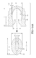
- FIGS. 14A through 14C show another tube 42 and groove 56 configuration.
- FIG. 14A is an enlarged view and 14B is a detailed view showing the tube 42 compressed and inserted into the groove 56.
- FIG. 14C is a detailed view showing the tube 42 fully inserted into the groove 56.
- the tube 42 may be generally elliptical in cross-section inserting into a like-configured groove 56.
- the groove 56 may have a narrow entryway formed between opposite parallel surfaces 148, 150.
- the tube 42 is configured having an external geometry and passageway configuration with dimensions within the ranges specified as follows:
- the example assembly comprises a bi-directionally peristaltic pump assembly 14 for air maintenance of a tire 12.
- the circular air tube 42 flattens, segment by segment, and closes in the tire footprint 100.
- the air inlet device 68 preferably includes an outer filter sleeve 92 formed of porous cellular material and thereby render the air inlet device 68 self-cleaning.
- the outlet device 70 may employ a valve unit (see US-A-2011/0272073 , incorporated herein by reference).
- the peristaltic pump assembly 14 may pump air through rotation of the tire 12 in either direction, one half of a revolution pumping air to the tire cavity 40 and the other half of a revolution pumping air back out of the inlet device 68.
- the peristaltic pump assembly 14 may be used with a secondary tire pressure monitoring system (TPMS) (not shown) that may serve as a system fault detector.
- TPMS secondary tire pressure monitoring system
- the TPMS may be used to detect any fault in the self-inflation system of the tire assembly 10 and alert the user of such a condition.
- the tire air maintenance system 10 may further incorporate a variable pressure pump groove 56 with one or more inwardly directed ridges or ribs 66 engaging and compressing a segment of the air tube 42 opposite such rib(s).
- the pitch or frequency of the ribs may increase toward the outlet device 70 for gradually reducing air volume within the passageway 43 by compressing the tube 42.
- the reduction in air volume may increase air pressure within the passageway 43 and thereby facilitate a more efficient air flow from the tube 42 into the tire cavity 40.
- the increase in tube pressure may be achieved by engagement by the ribs 66 of the groove 56 and the tube 42 having uniform dimensions along the tube length.
- the tube 42 may thus be made of uniform dimension and of relatively smaller size without compromising the flow pressure of air to the tire cavity 40 for maintaining air pressure.
- the pitch and amplitude of the ridges 66 may both be varied to better achieve the desired pressure increase within the passageway 43.
- Structures in a pneumatic tire may require the embedding of certain rigid parts, functional devices, and/or connectors into adhering onto the rubber of the tire.
- the structures 14, 42, 68, 70, 101, 202 of the example air maintenance tire 12 described above may require embedding/adherence.
- Such structures 14, 42, 68, 70, 101, 202 typically encounter high stresses during operating conditions of the tire 10.
- strong bonding of such structures 14, 42, 68, 70, 101, 202 is desired since a bond break at the structure's 14, 42, 68, 70, 101, 202, etc. surface will likely lead to destruction of the assembly 14 and/or the integrity of the tire 12 as a whole.
- an ultra high molecular weight polyethylene (UHMWPE) elbow-like structure 70 may be bonded to a tire 12 in order to define a built-in tube-like cavity ( FIG. 3C ).
- This structure 70 may thereby allow rerouting of pressurized air to a pump assembly 14 and from there, into a tire cavity 40, as well as to make a connection to the outside for providing fresh unpressurized air to the pump assembly.
- UHMWPE structures 14, 42, 68, 70, 101, 202 may be used.
- UHMWPE is similar to standard polyethylene, but has viscous flow shifted to significantly higher temperatures due to the much higher molecular weight and/or chain length. Thus, UHMWPE may bond at its surface to rubber at elevated temperatures through polymer chain entanglement, without losing its initial shape.
- the UHMWPE structures 14, 42, 68, 70, 101, 202, as well as any other build-in connectors inserts, and rigid parts, may be pressure sintered and machined from bulk and bonded to the tire 12. This bonding may reduce complexity and cost.
- FIG. 1 An example UHMWPE structure 14, 42, 68, 70, 101, 202 in accordance with the present invention is shown in cross-section in FIG. 1 , with a plurality of layers of tape 222 disposed on a surface 228.
- the layers 222 may be stacked and overlapped in such a manner as to form a desired bond strength.
- the layers of tape 222 may be fused by application of heat during cure of a tire 12, or by action of an adhesive applied to tape 222.
- the relatively thin tape 222 allows easy handling and application of the thermoplastic during tire building without need for thermal softening.
- Suitable thermoplastic materials for use as the tape 222 may include polyolefin such as polyethylene and polypropylene; polyamides such as nylon 6, nylon 6,6; nylon 6,12; polyesters such as polyethylene terephthalate (PET) and polybutylene terephthalate (PBT); polyphenylene ether (PPE); polyphthalamide (PPA); and the like.
- Suitable thermoplastic materials preferably have a melting temperature greater than the temperatures experienced during operating conditions of the tire 12.
- the thermoplastic material preferably has a melting temperature greater than 160°C or a melting temperature greater than 130°C.
- the thermoplastic material may be treated on its surface with an adhesive to promote adhesion between the layers of tape 222 and the adhesion between the tape 222 and the adjacent UHMWPE structures 14, 42, 68, 70, 101, 202.
- the tape 222 may be dipped in an RFL (resorcinol-formaldehyde-latex) type adhesive, an epoxy-based adhesive, and/or a combination of RFL and epoxy-based adhesives.
- the adhesive if used, may then be disposed between the layers of tape 22 in the UHMWPE structure 14, 42, 68, 70, 101, 202.
- Other components of the tire 12 may be made from rubber compositions with rubbers or elastomers containing olefinic unsaturation.
- the phrase "rubber or elastomer containing olefinic unsaturation" is intended to include both natural rubber and its various raw and reclaim forms, as well as various synthetic rubbers.
- Representative synthetic polymers may be the homopolymerization products of butadiene and its homologues and derivatives, for example, methyl butadiene, dimethylbutadiene and pentadiene, as well as copolymers such as those formed from butadiene or its homologues or derivatives with other unsaturated monomers.
- acetylenes for example, vinyl acetylene
- olefins for example, isobutylene, which copolymerizes with isoprene to form butyl rubber
- vinyl compounds for example, acrylic acid, acrylonitrile (which polymerize with butadiene to form NBR), methacrylic acid and styrene, the latter compound polymerizing with butadiene to form SBR, as well as vinyl esters and various unsaturated aldehydes, ketones, and ethers (e.g., acrolein, methyl isopropenyl ketone , and/or vinylethyl ether).
- acetylenes for example, vinyl acetylene
- olefins for example, isobutylene, which copolymerizes with isoprene to form butyl rubber
- vinyl compounds for example, acrylic acid, acrylonitrile (which polymerize with butadiene to form NBR), me
- synthetic rubbers may include neoprene (polychloroprene), polybutadiene (including cis-1,4-polybutadiene), polyisoprene (including cis-1,4-polyisoprene), butyl rubber, halobutyl rubber such as chlorobutyl rubber or bromobutyl rubber, styrene/isoprene/butadiene rubber, copolymers of 1,3-butadiene or isoprene with monomers such as styrene, acrylonitrile, and/or methyl methacrylate, as well as ethylene/propylene terpolymers (also known as ethylene/propylene/diene monomer (EPDM)), and/or ethylene/propylene/ dicyclopentadiene terpolymers.
- neoprene polychloroprene
- polybutadiene including cis-1,4-polybutadiene
- Rubbers which may be used include alkoxy-silyl end functionalized solution polymerized polymers (SBR, PBR, IBR, and/or SIBR), silicon-coupled and tin-coupled star-branched polymers. Rubber and/or elastomers may be polybutadiene and SBR.
- the rubber may be at least two diene based rubbers.
- a combination of two or more rubbers may be cis 1,4-polyisoprene rubber (natural or synthetic), 3,4-polyisoprene rubber, styrene/isoprene/butadiene rubber, emulsion and solution polymerization derived styrene/butadiene rubbers, cis 1,4-polybutadiene rubbers, and emulsion polymerization prepared butadiene/acrylonitrile copolymers.
- E-SBR emulsion polymerization derived styrene/butadiene
- An E-SBR may be used having a styrene content of 20% to 28% bound styrene or, for some applications, an E-SBR having a medium to relatively high bound styrene content (e.g., a bound styrene content of 30% to 45%).
- pl may refer to "parts by weight of a respective material per 100 parts by weight of rubber or elastomer.”
- the rubber composition is compounded by methods known in the rubber compounding art, such as mixing the various sulfur-vulcanizable constituent rubbers with various commonly used additive materials such as, for example, sulfur donors, curing aids, such as activators and retarders and processing additives, such as oils, resins including tackifying resins and plasticizers, fillers, pigments, fatty acid, zinc oxide, waxes, antioxidants and antiozonants and peptizing agents.
- additives may be selected and used in suitable amounts.
Landscapes
- Engineering & Computer Science (AREA)
- Mechanical Engineering (AREA)
- Tires In General (AREA)
Abstract
Description
- The invention relates generally to bonding parts to a pneumatic tire and, more specifically, to bonding parts of a pumping assembly to a pneumatic tire.
- Normal air diffusion reduces tire pressure over time. The natural state of tires is under inflated. Accordingly, drivers must repeatedly act to maintain tire pressures or they will see reduced fuel economy, tire life and reduced vehicle braking and handling performance. Tire Pressure Monitoring Systems have been proposed to warn drivers when tire pressure is significantly low. Such systems, however, remain dependent upon the driver taking remedial action when warned to re-inflate a tire to recommended pressure. It is a desirable, therefore, to incorporate an air maintenance feature within a tire that will maintain air pressure within the tire in order to compensate for any reduction in tire pressure over time without the need for driver intervention.
- The invention relates to a tire in accordance with
claim 1 and to a method in accordance with claim 15. - Dependent claims refer to preferred embodiments of the invention.
- In one aspect of the present invention, a pneumatic tire assembly may comprise: A tire having a pneumatic cavity; a rigid structure for facilitating operation of the tire assembly, the rigid structure being bonded to the tire by a layered thermoplastic material such that a stiffness gradient is created between the structure and the tire; first and second sidewalls extending respectively from first and second tire bead regions to a tire tread region, the first sidewall having at least one bending region operatively bending when radially within a rolling tire footprint; and a sidewall groove defined by groove walls positioned within the bending region of the first tire sidewall, the sidewall groove deforming segment by segment between a non-deformed state and a deformed, constricted state in response to bending of the bending region of the first sidewall while radially within the rolling tire footprint. An air passageway is defined by the sidewall groove and deforms segment by segment between an expanded condition and an at least partially collapsed condition in response to respective segment by segment deformation of the sidewall groove when radially within the rolling tire footprint.
- According to one aspect of the invention, the thermoplastic material may be selected from the group consisting of polyethylene, polypropylene, polyamide, polyester, polyphenylene ether, and polyphthalamide.
- According to another aspect of the invention, the thermoplastic material may be polyethylene.
- According to yet another aspect of the invention, the rigid structure may further comprise an adhesive selected from the group consisting of an RFL adhesive and an epoxy-based adhesive.
- According to still another aspect of the invention, the thermoplastic material may comprise a plurality of thermoplastic layers.
- According to yet another aspect of the invention, the thermoplastic material may comprise a plurality of thermoplastic layers wherein the thermoplastic layers have a layer thickness ranging from 0.1 to 1 mm.
- According to still another aspect of the invention, the thermoplastic material may comprise at least ten thermoplastic layers.
- According to yet another aspect of the invention, the thermoplastic material may comprise a plurality of thermoplastic layers with an adhesive disposed between the thermoplastic layers.
- According to still another aspect of the invention, the thermoplastic material may comprise at least ten thermoplastic layers with an adhesive disposed between the thermoplastic layers.
- According to yet another aspect of the invention, the rigid structure may be constructed of ultra high molecular weight polyethylene.
- According to still another aspect of the invention, the rigid structure and the tire may define a built-in tube-like cavity.
- According to yet another aspect of the invention, the rigid structure and the tire preferably reroute pressurized air to a pump assembly, and from there, into the pneumatic cavity.
- According to still another aspect of the invention, a separate tube may be disposed within the sidewall groove, the separate tube defining a circular air passageway.
- According to yet another aspect of the invention, the separate tube preferably has an outer profile corresponding to an inner profile of the sidewall groove.
- According to still another aspect of the invention, the rigid structure preferably comprises a plurality of check valves disposed at multiple arcuate positions about the sidewall groove.
- According to still another aspect of the invention, a subcoat may be applied to a bare surface of the rigid structure and a topcoat may be applied to the subcoat.
- According to still another aspect of the pneumatic tire assembly, the subcoat may be dried to the bare surface of the rigid structure for instance at 180C for 8 min.
- "Axial" and "axially" means lines or directions that are parallel to the axis of rotation of the tire.
- "Circumferential" means lines or directions extending along the perimeter of the surface of the annular tread perpendicular to the axial direction.
- "Equatorial Centerplane (CP)" means the plane perpendicular to the tire's axis of rotation and passing through the center of the tread.
- "Footprint" means the contact patch or area of contact of the tire tread with a flat surface at zero speed and under normal load and pressure.
- "Lateral" means an axial direction.
- "Peristaltic" means operating by means of wave-like contractions that propel contained matter, such as air, along tubular pathways.
- "Radial" and "radially" means directions radially toward or away from the axis of rotation of the tire.
- The invention will be described by way of example and with reference to the accompanying drawings in which:
- Fig-1; Schematic cross-sectional view of an example assembly in accordance with the present invention.
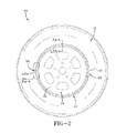
- Fig-2; Side view of the example tire/tube assembly.
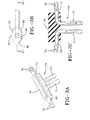
- Fig-3A-3C; Details of an example outlet connector.
- Fig-4A-4E; Details of an example inlet (filter) connector.
- Fig-5A; Side view of an example tire rotating with air movement (84) to cavity.
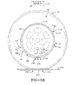
- Fig-5B; Side view of the example tire rotating with air flushing out filter.
- Fig-6A; Section view taken from Fig-5A.
- Fig-6B; Enlarged detail of tube area taken from Fig-6A, sidewall in non-compressed state.
- Fig-7A; Section view taken from Fig-5A.
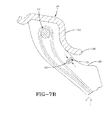
- Fig-7B; Enlarged detail of tube area taken from Fig-7A, sidewall in compressed state.
- Fig-8A; Enlarged detail of an example tube & groove detail taken from Fig-2.
- Fig-8B; Detail showing an example tube compressed and being inserted into the groove.
- Fig-8C; Detail showing an example tube fully inserted into the groove at a ribbed area of the groove.
- Fig-8D; Exploded fragmented view of tube being inserted into a ribbed groove.
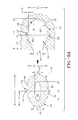
- Fig-9; Enlarged detail taken from Fig-2 showing an example rib profile area located on both sides of the outlet to a cavity connector.
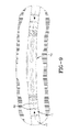
- Fig-10A; Enlarged detail of the groove with the example rib profile.
- Fig-10B; Enlarged detail of tube pressed into the example rib profile.
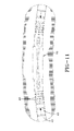
- Fig-11; Enlarged detail taken from Fig-2 showing another example rib profile area located on both sides of the outlet to a cavity connector.
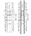
- Fig-12A; Enlarged detail of the groove with the other example rib profile.
- Fig-12B; Enlarged detail of the tube pressed into the other example rib profile.
- Fig-13A; Enlarged view of another example tube & groove detail.
- Fig-13B; Detail showing tube from Fig-13A being compressed and inserted into the groove.
- Fig-13C; Detail showing the tube from Fig-13A fully inserted into the groove.
- Fig-14A; Enlarged view of a third example tube & groove detail.
- Fig-14B; Detail showing tube from Fig-14A being compressed and inserted into the groove.
- Fig-14C; Detail showing the tube from Fig-14A fully inserted into the groove.
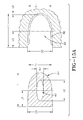
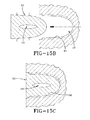
- Fig-15A; Enlarged view of a fourth example tube & groove detail.
- Fig-15B; Detail showing tube from Fig-15A being compressed and inserted into the groove.
- Fig-15C; Detail showing the tube from Fig-15A fully inserted into the groove.
-
Fig. 16 ; Isometric exploded view of an example tire and tube assembly for use with the present invention. - Referring to
FIGS. 16 ,2 , and6A , anexample tire assembly 10 includes atire 12, aperistaltic pump assembly 14, and atire rim 16. The tire mounts in conventional fashion to a pair ofrim mounting surfaces outer rim flanges flange end 26. Arim body 28 may support thetire assembly 10 as shown. Thetire 12 may be of conventional construction, having a pair ofsidewalls opposite bead areas tire tread region 38. Thetire 12 and rim 16 enclose atire cavity 40. - As seen from
FIGS. 2 and3A, 3B, 3C ,6B and8A , the exampleperistaltic pump assembly 14 includes anannular air tube 42 that encloses anannular passageway 43. Thetube 42 is formed of a resilient, flexible material such as plastic or rubber compounds that are capable of withstanding repeated deformation cycles of a flattened condition subject to external force and, upon removal of such force, returned to an original condition generally circular in cross-section. Thetube 42 has a diameter sufficient to operatively pass a volume of air for purposes described herein and allowing a positioning of the tube in an operable location within thetire assembly 10 as will be described below. In the example configuration shown, thetube 42 may be an elongate, generally elliptical shape in cross-section, having opposite tube sidewalls 44, 46 extending from a flat (closed) trailingtube end 48 to a radiussed (open) leadingtube end 50. Thetube 42 may have a longitudinal outwardly projecting pair oflocking detent ribs 52 of generally semi-circular cross-section and each rib extending along outward surfaces of thesidewalls - As referenced in
FIG 8A , thetube 42 may have a length L1 within a range of 3.65 mm to 3.80 mm; a width of D1 within a range of 2.2 mm to 3.8 mm; a trailing end width of D3 within a range of 0.8 mm to 1.0 mm. The protrudingdetent ribs tube end 48. The leadingend 50 of thetube 42 may have a radius R1 within a range of 1.1 mm to 1.9 mm. Theair passageway 43 within thetube 42 may likewise be generally elliptical with a length L2 within a range of 2.2 mm to 2.3 mm; and a width D2 within a range of 0.5 mm to 0.9 mm. - The
tube 42 is profiled and geometrically configured for insertion into agroove 56. Thegroove 56 may have an elongate, generally elliptical configuration with a length L1 within a range of 3.65 mm to 3.80 mm complementary to the elliptical shape of thetube 42. Thegroove 56 may include a restrictednarrower entryway 58 having a nominal cross-sectional width D3 within a range of 0.8 mm to 1.0 mm. A pair of groove-rib receivingaxial detent channels groove 56 for corresponding receipt of thetube locking ribs channels groove entryway 58.Detent channels detent groove portion 64 may be formed with a radius of curvature R1 within a range of 1.1 mm to 1.9 mm and a cross-sectional nominal width D1 within a range of 2.2 mm to 3.8 mm. - As best seen from
FIGS. 8D ,9 ,10A and 10B , thetire 12 may further form one ormore compression ribs 66 extending the circumference of, and projecting into, thegroove 56. Theribs 66 may form a pattern of ribs of prescribed pitch, frequency, and location, as described below. For the purpose of explanation, seven compression ribs may be referred to generally by numeral 66 in the first rib profile pattern shown, and specifically by the rib designations D0 through D6. The ribs D0 through D6 may be formed in a sequence and pitch pattern in order to optimize the pumping of air through thetube passageway 43. Theribs 66 may each have a unique and predetermined height and placement within the pattern and, as shown inFIG. 8D , project outward into thegroove 56 at a radius R3 (FIG. 8A ) within a range of 0.95 mm to 1.60 mm. - With reference to
FIGS. 16 ,2 ,3A through 3C, and4A through E, theperistaltic pump assembly 14 further includes aninlet device 68 and anoutlet device 70 preferable spaced apart approximately 180 degrees at respective locations along thecircumferential air tube 42. Theexample outlet device 70 has a T-shaped configuration in whichconduits tire cavity 40. Anoutlet device housing 76 containsconduit arms respective conduits conduit arms external coupling ribs air tube 42 in the assembled condition. Thehousing 76 is formed having an external geometry that complements thegroove 56 and includes aflat end 86, a radiused generally oblongbody 88, and outwardly projectinglongitudinal detent ribs 90. Thehousing 76 may thus be capable of close receipt into thegroove 56 at its intended location with theribs 90 registering within thegroove 56 as represented inFIG. 8A . - The
inlet device 68, as seen inFIGS. 12 ,4A through 4E , may include an elongateoutward sleeve body 94 joining an elongateinward sleeve body 96 at anarrow sleeve neck 98. The outward sleeve body is generally triangular in section. Theinward sleeve body 96 has an oblong external geometry complementary to thegroove 56 and includes a pair ofdetent ribs 100 extending longitudinally along the inward sleeve body. An elongateair entry tube 101 is positioned within theinward sleeve body 96 and includes opposite tube ends 102 and a pattern ofentry apertures 104 extending into a central tube passageway.External ribs air tube 42 opposite theoutlet device 70. - As shown in
FIGS. 6A ,6B ,7A ,7B ,8A through D, thepump assembly 14 comprises theair tube 42 and inlet andoutlet devices groove 56. Thegroove 56 may be located at a lower sidewall region of thetire 12 that, when the tire is mounted to therim 16, positions theair tube 42 above the rim flange ends 26.FIG. 8B shows theair tube 42 diametrically squeezed and collapsed to accommodate insertion into thegroove 56. Upon full insertion, as shown inFIG. 8C , theribs groove channels outer end 48 of thetube 42 may be generally coplanar with the outer surface of the sidewall of the tire. Once fully inserted, theair passageway 43 of thetube 42 may elastically restore itself into an open condition to allow the flow of air along the tube during operation of the pump. - Referring to
FIGS. 16 ,2 ,5A ,5B ,6A ,6B ,7A ,7B ,8A through 8D , theinlet device 68 and theoutlet device 70 may be positioned within the circumference of thecircular air tube 42 generally 180 degrees apart. Thetire 12 with thetube 42 positioned withingroove 56 rotates in a direction ofrotation 110, causing afootprint 120 to be formed against theground surface 118. Acompressive force 124 is directed into thetire 12 from thefootprint 120 and acts to flatten a segment of theair tube passageway 43 opposite thefootprint 120, as shown atnumeral 122. Flattening of a segment of thepassageway 43 forces air from the segment along thetube passageway 43 in the direction shown byarrow 116, toward theoutlet device 70. - As the
tire 12 continues to rotate in thedirection 110 along theground surface 118, thetube 42 may be sequentially flattened or squeezed opposite the tire footprint, segment by segment, in a direction opposite to thedirection 110. A sequential flattening of thetube passageway 43, segment by segment, may cause evacuated air from the flattened segments to be pumped in thedirection 116 withintube passageway 43 toward theoutlet device 70. Air may flow through theoutlet device 70 and to thetire cavity 40, as shown at 130. At 130, air exiting theoutlet device 70 may be routed to thetire cavity 40 and serve to re-inflate thetire 12 to a desired pressure level. A valve system to regulate the flow of air to thecavity 40, when the air pressure within the cavity falls to a prescribed level, is shown and described in pendingUS-A- 2011/0272073 incorporated herein by reference. - With the
tire 12 rotating indirection 110, flattened tube segments may be sequentially refilled by air flowing into theinlet device 68 in thedirection 114, as shown byFIG. 5A . The inflow of air into theinlet device 68, and then into thetube passageway 43, may continue until theoutlet device 70, rotating in acounterclockwise direction 110, passes thetire footprint 120.FIG. 5B shows the orientation of theperistaltic pump assembly 14 in such a position. Thetube 42 may continue to be sequentially flattened, segment by segment, opposite thetire footprint 120 by acompressive force 124. Air may be pumped in theclockwise direction 116 to theinlet device 68 and evacuated or exhausted external to thetire 12. Passage of exhaust air, as shown at 128, from theinlet device 68 may occur through afilter sleeve 92 exemplarily formed of a cellular or porous material or composite. Flow of air through thefilter sleeve 92 and into thetube 101 may thus cleanse debris or particulates. In the exhaust or reverse flow ofair direction 128, thefilter sleeve 92 may be cleansed of trapped accumulated debris or particles within the porous medium. With the evacuation of pumped air out of theinlet device 68, theoutlet device 70 may be in a closed position preventing air flow to thetire cavity 40. When thetire 12 rotates further incounterclockwise direction 110 until theinlet device 70 passes the tire footprint 120 (as shown inFIG. 5A ), the airflow may resume to the outlet device and cause the pumped air to flow out and into thetire cavity 40. Air pressure within thetire cavity 40 may thus be maintained at a desired level. -
FIG. 5B illustrates that thetube 42 is flattened, segment by segment, as thetire 12 rotates indirection 110. A flattenedsegment 134 moves counterclockwise as it is rotated away from thetire footprint 120 while anadjacent segment 132 moves opposite the tire footprint and is flattened. Accordingly, the progression of squeezed or flattened or closed tube segments may be move air toward the outlet device 70 (FIG. 5A ) or the inlet device 68 (FIG. 5B ) depending on the rotational position of thetire 12 relative to such devices. As each segment is moved by tire rotation away from thefootprint 120, the compression forces within thetire 12 from the footprint region may be eliminated and the segment may resiliently reconfigure into an unflattened or open condition as the segment refills with air from thepassageway 43.FIGS. 7A and7B show a segment of thetube 42 in the flattened condition whileFIGS. 6A and6B show the segment in an expanded, unflat or open configuration prior to, and after, moving away from a location opposite thetire footprint 120. In the original non-flattened configuration, segments of thetube 42 may resume the exemplary oblong generally elliptical shape. - The above-described cycle may repeat for each tire revolution, with half of each rotation resulting in pumped air moving to the
tire cavity 40 and half of each rotation resulting in pumped air moving back out thefilter sleeve 92 of theinlet device 68 for self-cleaning the filter. It may be appreciated that while the direction ofrotation 110 of thetire 12 is as shown inFIGS. 5A and5B is counterclockwise, thesubject tire assembly 10 and itsperistaltic pump assembly 14 may function in a like manner in a reverse (clockwise) direction of rotation as well. Theperistaltic pump assembly 14 may accordingly be bi-directional and equally functional with thetire 12 and vehicle moving in a forward or reverse direction of rotation and forward or reverse direction of the vehicle. - The air tube/
pump assembly 14 may be as shown inFIGS.5A ,5B ,6A ,6B ,7A and7B . Thetube 42 may be located within thegroove 56 in a lower region of thesidewall 30 of thetire 12. Thepassageway 43 of thetube 42 may close by compression strain bending of thesidewall groove 56 within a rollingtire footprint 120, as explained above. The location of thetube 42 in thesidewall 30 may provide freedom of placement thereby avoiding contact between thetube 42 and therim 16. Higher placement of thetube 42 in thesidewall groove 56 may use high deformation characteristics of this region of the sidewall as it passes through thetire footprint 120 to close thetube 42. - The configuration and operation of the grooved sidewalls, and in particular the variable pressure pump compression of the
tube 42 by operation of ridges orcompression ribs 66 within thegroove 56 is shown inFIGS. 8A-8D ,9, 10A and 10B . The ridges or ribs are indicated bynumeral 66 and individually as D0 through D6. Thegroove 56 may be uniform width circumferentially along the side of thetire 12 with the molded ridges D0 through D6 formed to project into thegroove 56 in a preselected sequence, pattern, or array. The ridges D0 through D6 may retain thetube 42 in a predetermined orientation within thegroove 56 and also may apply a variable sequential constriction force to the tube. - The uniformly dimensioned
pump tube 42 may be positioned within thegroove 56 as explained above - a procedure initiated by mechanically spreading the entryway D3 of thegroove 56 apart. Thetube 42 may then be inserted into the enlarged opening of thegroove 56. The opening of thegroove 56 may thereafter be released to return to close into the original spacing D3 and thereby capture thetube 42 inside the groove. Thelongitudinal locking ribs longitudinal grooves ribs tube 42 inside thegroove 56 and prevent ejection of the tube from thegroove 56 during tire operation/rotation. - Alternatively, the
tube 42 may be press inserted into thegroove 56. Thetube 42, being of uniform width dimensions and geometry, may be manufactured in large quantities. Moreover, a uniform dimensionedpump tube 42 may reduce overall assembly time, material cost, and non-uniformity of tube inventory. From a reliability perspective, this results in less chance for scrap. - The circumferential ridges D0 through D6 projecting into the
groove 56 may increase in frequency (number of ridges per axial groove unit of length) toward the inlet passage of thetube 42, represented by theoutlet device 70. Each of the ridges D0 through D6 may have a common radius dimension R4 within a range of 0.15 mm to 0.30 mm. The spacing between ridges D0 and D1 may be largest, the spacing between D1 and D2 the next largest, and so on until the spacing between ridges D5 and D6 is nominally eliminated. While seven ridges are shown, more or fewer ridges may be deployed at various frequency along thegroove 56. - The projection of the ridges into the
groove 56 by radius R4 may serve a twofold purpose. First, the ridges D0 through D6 may engage thetube 42 and prevent the tube from migrating, or "walking", along thegroove 56 during tire operation/rotation from the intended location of the tube. Secondly, the ridges D0 through D6 may compress the segment of thetube 42 opposite each ridge to a greater extent as thetire 12 rotates through its rotary pumping cycle, as explained above. The flexing of the sidewall may manifest a compression force through each ridge D0 through D6 and may constrict the tube segment opposite such ridge to a greater extent than otherwise would occur in tube segments opposite non-ridged portions of thegroove 56. As seen inFIGS. 10A and 10B , as the frequency of the ridges increases in the direction of air flow, a pinching of thetube passageway 43 may progressively occur until the passageway constricts to the size shown atnumeral 136, gradually reducing the air volume and increasing the pressure. As a result, with the presence of the ridges, thegroove 56 may provide variable pumping pressure within thetube 42 configured to have a uniform dimension therealong. As such, thesidewall groove 56 may be a variable pressure pump groove functioning to apply a variable pressure to atube 42 situated within the groove. It will be appreciated that the degree of pumping pressure variation may be determined by the pitch or ridge frequency within thegroove 56 and the amplitude of the ridges deployed relative to the diametric dimensions of thetube passageway 43. The greater the ridge amplitude relative to the diameter, the more air volume may be reduced in the tube segment opposite the ridge and pressure increased, and vice versa.FIG. 9 depicts the attachment of thetube 42 to theoutlet device 70 and the direction of air flow on both sides into outlet device. -
FIG. 11 shows a second alternative rib profile area located on both sides of the outlet to theoutlet device 70.FIG. 12A shows an enlarged detail of thegroove 56 with the alternative second rib profile andFIG. 12B shows an enlarged detail of thetube 42 pressed into the second rib profile. With reference toFIGS. 11 ,12A, 12B , the ridges, or ribs, D0 through D6 in this alternative may have a frequency pattern similar to that described above in reference toFIGS. 10A, 10B , but with each rib having a unique respective amplitude as well. Each of the ribs D0 through D6 may generally have a semi-circular cross-section with a respective radius of curvature R1 through R7, respectively. The radii of curvatures of the ridges/ D0 through D6 may be within the exemplary range: Δ = 0.020 mm to 0.036 mm. - The number of ridges D0 through D6 and respective radii of each ridge may be constructed outside the above ranges to suit other dimensions or applications. The increasing radius of curvature in the direction of air flow may result in the ridges D0 through D6 projecting at an increasing amplitude and, to an increasing extent, into the
passageway 43 toward theoutlet device 70. As such, thepassageway 43 may constrict to anarrower region 138 toward theoutlet device 70 and cause a correspondingly greater increase in air pressure from a reduction in air volume. The benefit of such a configuration is that thetube 42 may be constructed smaller than otherwise necessary in order to achieve a desired air flow pressure along thepassageway 43 and into thetire cavity 40 from theoutlet device 70. A smallersized tube 42 may be economically and functionally desirable in allowing asmaller groove 56 within thetire 12 to be used, thereby resulting a minimal structural discontinuity in the tire sidewall. -
FIGS. 13A through 13 °C show anothertube 42 andgroove 56 detail in which thedetent ribs 90 ofFIG. 8A through 8 °C are eliminated as a result of rib and groove modification. Thistube 42 may have an external geometry and passageway configuration with indicated dimensions within ranges specified as follows: - D1= 2.2 to 3.8 mm;
- D2= 0.5 to 0.9 mm;
- D3= 0.8 to 1.0 mm;
- R4= 0.15 to 0.30 mm;
- L1= 3.65 to 3.8 mm;
- L2= 2.2 to 2.3 mm;
- L3=1.8 to 2.0 mm.
- The above ranges may be modified to suit a particular dimensional preference, tire geometry, or tire application. The external configuration of the
tube 42 may includebeveled surfaces end surface 48; parallel and opposite straightintermediate surfaces forward surface 146, adjoining theintermediate surfaces FIGS. 13B and 13C , thetube 42 may be compressed for press insertion into thegroove 56 and, upon full insertion, expand. The constricted opening of thegroove 56 at the sidewall surface may retain thetube 42 securely within thegroove 56. -
FIGS. 14A through 14C show anothertube 42 andgroove 56 configuration.FIG. 14A is an enlarged view and 14B is a detailed view showing thetube 42 compressed and inserted into thegroove 56.FIG. 14C is a detailed view showing thetube 42 fully inserted into thegroove 56. Thetube 42 may be generally elliptical in cross-section inserting into a like-configuredgroove 56. Thegroove 56 may have a narrow entryway formed between oppositeparallel surfaces FIGS. 14A through 14C , thetube 42 is configured having an external geometry and passageway configuration with dimensions within the ranges specified as follows: - D1= 2.2 to 3.8 mm;
- D2= 0.5 to 0.9 mm;
- D3=0.8 to 1.0 mm;
- R4= 0.15 to 0.30 mm;
- L1= 3.65 to 3.8 mm;
- L2= 2.2 to 2.3 mm;
- L3= 1.8 to 2.0 mm.
- D1= 2.2 to 3.8 mm;
- D2= 0.5 to 0.9 mm;
- D3= 2.5 to 4.1 mm;
- L1= 3.65 to 3.8 mm;
- L2= 2.2 to 2.3 mm;
- L3= 1.8 to 2.0 mm.
- From the forgoing, it will be appreciated that the example assembly comprises a bi-directionally
peristaltic pump assembly 14 for air maintenance of atire 12. Thecircular air tube 42 flattens, segment by segment, and closes in thetire footprint 100. Theair inlet device 68 preferably includes anouter filter sleeve 92 formed of porous cellular material and thereby render theair inlet device 68 self-cleaning. Theoutlet device 70 may employ a valve unit (seeUS-A-2011/0272073 , incorporated herein by reference). Theperistaltic pump assembly 14 may pump air through rotation of thetire 12 in either direction, one half of a revolution pumping air to thetire cavity 40 and the other half of a revolution pumping air back out of theinlet device 68. Theperistaltic pump assembly 14 may be used with a secondary tire pressure monitoring system (TPMS) (not shown) that may serve as a system fault detector. The TPMS may be used to detect any fault in the self-inflation system of thetire assembly 10 and alert the user of such a condition. - The tire
air maintenance system 10 may further incorporate a variablepressure pump groove 56 with one or more inwardly directed ridges orribs 66 engaging and compressing a segment of theair tube 42 opposite such rib(s). The pitch or frequency of the ribs may increase toward theoutlet device 70 for gradually reducing air volume within thepassageway 43 by compressing thetube 42. The reduction in air volume may increase air pressure within thepassageway 43 and thereby facilitate a more efficient air flow from thetube 42 into thetire cavity 40. The increase in tube pressure may be achieved by engagement by theribs 66 of thegroove 56 and thetube 42 having uniform dimensions along the tube length. Thetube 42 may thus be made of uniform dimension and of relatively smaller size without compromising the flow pressure of air to thetire cavity 40 for maintaining air pressure. The pitch and amplitude of theridges 66 may both be varied to better achieve the desired pressure increase within thepassageway 43. - Structures in a pneumatic tire may require the embedding of certain rigid parts, functional devices, and/or connectors into adhering onto the rubber of the tire. For example, the
structures air maintenance tire 12 described above may require embedding/adherence.Such structures tire 10. Thus, strong bonding ofsuch structures assembly 14 and/or the integrity of thetire 12 as a whole. - For example, an ultra high molecular weight polyethylene (UHMWPE) elbow-
like structure 70 may be bonded to atire 12 in order to define a built-in tube-like cavity (FIG. 3C ). Thisstructure 70 may thereby allow rerouting of pressurized air to apump assembly 14 and from there, into atire cavity 40, as well as to make a connection to the outside for providing fresh unpressurized air to the pump assembly. - In order to optimally bond
such structures tire 12,UHMWPE structures UHMWPE structures tire 12. This bonding may reduce complexity and cost. - An
example UHMWPE structure FIG. 1 , with a plurality of layers oftape 222 disposed on asurface 228. Thelayers 222 may be stacked and overlapped in such a manner as to form a desired bond strength. The layers oftape 222 may be fused by application of heat during cure of atire 12, or by action of an adhesive applied totape 222. With the present method, the relativelythin tape 222 allows easy handling and application of the thermoplastic during tire building without need for thermal softening. - Suitable thermoplastic materials for use as the
tape 222 may include polyolefin such as polyethylene and polypropylene; polyamides such as nylon 6, nylon 6,6;nylon 6,12; polyesters such as polyethylene terephthalate (PET) and polybutylene terephthalate (PBT); polyphenylene ether (PPE); polyphthalamide (PPA); and the like. Suitable thermoplastic materials preferably have a melting temperature greater than the temperatures experienced during operating conditions of thetire 12. The thermoplastic material preferably has a melting temperature greater than 160°C or a melting temperature greater than 130°C. The thermoplastic material may be treated on its surface with an adhesive to promote adhesion between the layers oftape 222 and the adhesion between thetape 222 and theadjacent UHMWPE structures tape 222 may be dipped in an RFL (resorcinol-formaldehyde-latex) type adhesive, an epoxy-based adhesive, and/or a combination of RFL and epoxy-based adhesives. The adhesive, if used, may then be disposed between the layers oftape 22 in theUHMWPE structure tire 12 may be made from rubber compositions with rubbers or elastomers containing olefinic unsaturation. The phrase "rubber or elastomer containing olefinic unsaturation" is intended to include both natural rubber and its various raw and reclaim forms, as well as various synthetic rubbers. - Representative synthetic polymers may be the homopolymerization products of butadiene and its homologues and derivatives, for example, methyl butadiene, dimethylbutadiene and pentadiene, as well as copolymers such as those formed from butadiene or its homologues or derivatives with other unsaturated monomers. Among the latter may be acetylenes, for example, vinyl acetylene; olefins, for example, isobutylene, which copolymerizes with isoprene to form butyl rubber; vinyl compounds, for example, acrylic acid, acrylonitrile (which polymerize with butadiene to form NBR), methacrylic acid and styrene, the latter compound polymerizing with butadiene to form SBR, as well as vinyl esters and various unsaturated aldehydes, ketones, and ethers (e.g., acrolein, methyl isopropenyl ketone , and/or vinylethyl ether). Specific examples of synthetic rubbers may include neoprene (polychloroprene), polybutadiene (including cis-1,4-polybutadiene), polyisoprene (including cis-1,4-polyisoprene), butyl rubber, halobutyl rubber such as chlorobutyl rubber or bromobutyl rubber, styrene/isoprene/butadiene rubber, copolymers of 1,3-butadiene or isoprene with monomers such as styrene, acrylonitrile, and/or methyl methacrylate, as well as ethylene/propylene terpolymers (also known as ethylene/propylene/diene monomer (EPDM)), and/or ethylene/propylene/ dicyclopentadiene terpolymers. Additional examples of rubbers which may be used include alkoxy-silyl end functionalized solution polymerized polymers (SBR, PBR, IBR, and/or SIBR), silicon-coupled and tin-coupled star-branched polymers. Rubber and/or elastomers may be polybutadiene and SBR.
- The rubber may be at least two diene based rubbers. For example, a combination of two or more rubbers may be cis 1,4-polyisoprene rubber (natural or synthetic), 3,4-polyisoprene rubber, styrene/isoprene/butadiene rubber, emulsion and solution polymerization derived styrene/butadiene rubbers, cis 1,4-polybutadiene rubbers, and emulsion polymerization prepared butadiene/acrylonitrile copolymers. An emulsion polymerization derived styrene/butadiene (E-SBR) may be used having a styrene content of 20% to 28% bound styrene or, for some applications, an E-SBR having a medium to relatively high bound styrene content (e.g., a bound styrene content of 30% to 45%).
- The term "phr" as used herein, may refer to "parts by weight of a respective material per 100 parts by weight of rubber or elastomer."
- It may be understood by those having skill in the art that the rubber composition is compounded by methods known in the rubber compounding art, such as mixing the various sulfur-vulcanizable constituent rubbers with various commonly used additive materials such as, for example, sulfur donors, curing aids, such as activators and retarders and processing additives, such as oils, resins including tackifying resins and plasticizers, fillers, pigments, fatty acid, zinc oxide, waxes, antioxidants and antiozonants and peptizing agents. Depending on the intended use of the sulfur vulcanizable and sulfur-vulcanized material (rubbers), the additives may be selected and used in suitable amounts.
Claims (15)
- A pneumatic tire comprising:a cavity (40), a first and a second sidewall (30, 32) extending respectively from a first and a second tire bead region (34, 36) to a tire tread region (38), the first sidewall having at least one bending region operatively bending when radially within a rolling tire footprint (120);a sidewall groove (56) defined by groove walls positioned within the bending region of the first tire sidewall (30), the sidewall groove (56) operatively deforming segment by segment between a non-deformed state and a deformed, constricted state in response to a bending of the bending region of the first sidewall (30) while radially within the rolling tire footprint (120);an air passageway (43) defined by the sidewall groove or located within the sidewall groove (56) and operatively deforming segment by segment between an expanded condition and an at least partially collapsed condition in response to respective segment by segment deformation of the sidewall groove (56) when radially within the rolling tire footprint (120); anda rigid structure (14, 42, 68, 70, 101) wherein the rigid structure (14, 42, 68, 70, 101) is bonded to the tire (12) by a layered thermoplastic material (222).
- The pneumatic tire of claim 1 wherein the thermoplastic material (222) is selected from the group consisting of polyethylene, polypropylene, polyamide, polyester, polyphenylene ether, and polyphthalamide.
- The pneumatic tire of claim 1 or 2 wherein the rigid structure (14, 42, 68, 70, 101) comprises or is coated with an adhesive selected from the group consisting of an RFL adhesive and an epoxy-based adhesive.
- The pneumatic tire of at least one of the previous claims wherein the layered thermoplastic material (222) comprises a plurality of thermoplastic layers such as at least ten thermoplastic layers.
- The pneumatic tire of claim 1 or 4 wherein the thermoplastic layer (222) or the thermoplastic layers each have a layer thickness ranging of from 0.1 to 1 mm.
- The pneumatic tire of at least one of the previous claims wherein the thermoplastic material comprises a plurality of thermoplastic layers such as at least ten thermoplastic layers with an adhesive disposed between the thermoplastic layers.
- The pneumatic tire of at least one of the previous claims wherein the rigid structure (14, 42, 68, 70, 101) is constructed of polyamide or an ultra high molecular weight polyethylene.
- The pneumatic tire as set forth in at least one of the previous claims wherein the rigid structure (14, 42, 68, 70, 101) and the tire (12) define a built-in tube-like cavity.
- The pneumatic tire as set forth in at least one of the previous claims wherein the rigid structure (14, 42, 68, 70, 101) and the tire (12) reroute pressurized air to a pump assembly and from there, into the cavity (40).
- The pneumatic tire as set forth in at least one of the previous claims further including a subcoat applied to a surface or bare surface of the rigid structure (14, 42, 68, 70, 101) and, optionally, a topcoat applied to the subcoat.
- The pneumatic tire as set forth in claim 10 or 11 wherein the layered thermoplastic material (222) is applied to the topcoat or to the subcoat.
- The pneumatic tire as set forth in at least one of the previous claims further including a separate tube (42) within the sidewall groove (56), the separate tube defining a circular air passageway, the separate tube (42) preferably having an outer profile corresponding to an inner profile of the sidewall groove (56).
- The pneumatic tire as set forth in at least one of the previous claims wherein the rigid structure comprises a plurality of check valves disposed at multiple arcuate positions about the sidewall groove (56).
- The pneumatic tire as set forth in at least one of the previous claims wherein the tire is a self-inflating tire.
- A method of manufacturing a pneumatic tire, the method comprising:providing a tire (12) having a cavity (40), a first and a second sidewall (30, 32) extending respectively from a first and a second tire bead region (34, 36) to a tire tread region (38), the first sidewall having at least one bending region operatively bending when radially within a rolling tire footprint (120), a sidewall groove (56) defined by groove walls positioned within the bending region of the first tire sidewall (30), the sidewall groove (56) operatively deforming segment by segment between a non-deformed state and a deformed, constricted state in response to a bending of the bending region of the first sidewall (30) while radially within the rolling tire footprint (120), an air passageway (43) defined by the sidewall groove or located within the sidewall groove (56) and operatively deforming segment by segment between an expanded condition and an at least partially collapsed condition in response to respective segment by segment deformation of the sidewall groove (56) when radially within the rolling tire footprint (120);providing a rigid structure (14, 42, 68, 70, 101) for bonding the rigid structure (14, 42, 68, 70, 101) to the tire (12); andbonding the rigid structure (14, 42, 68, 70, 101) to the tire (12) by a layered thermoplastic material (222).
Applications Claiming Priority (1)
| Application Number | Priority Date | Filing Date | Title |
|---|---|---|---|
| US13/561,155 US20140027032A1 (en) | 2012-07-30 | 2012-07-30 | Bonding to a pneumatic tire |
Publications (1)
| Publication Number | Publication Date |
|---|---|
| EP2692551A1 true EP2692551A1 (en) | 2014-02-05 |
Family
ID=48874923
Family Applications (1)
| Application Number | Title | Priority Date | Filing Date |
|---|---|---|---|
| EP13178354.0A Withdrawn EP2692551A1 (en) | 2012-07-30 | 2013-07-29 | Bonding to a pneumatic tire |
Country Status (5)
| Country | Link |
|---|---|
| US (1) | US20140027032A1 (en) |
| EP (1) | EP2692551A1 (en) |
| JP (1) | JP2014024545A (en) |
| CN (1) | CN103568744B (en) |
| BR (1) | BR102013019403A2 (en) |
Families Citing this family (4)
| Publication number | Priority date | Publication date | Assignee | Title |
|---|---|---|---|---|
| US9381781B2 (en) | 2012-07-30 | 2016-07-05 | The Goodyear Tire & Rubber Company | Bonding to a pneumatic tire |
| US20140027030A1 (en) * | 2012-07-30 | 2014-01-30 | Andreas Frantzen | Adhesive bonding for a pneumatic tire |
| US9266389B2 (en) * | 2013-07-19 | 2016-02-23 | The Boeing Company | Wheel system for a vehicle |
| US9365084B2 (en) * | 2013-12-11 | 2016-06-14 | The Goodyear Tire & Rubber Company | Self-inflating tire and pressure regulator |
Citations (7)
| Publication number | Priority date | Publication date | Assignee | Title |
|---|---|---|---|---|
| US3304981A (en) * | 1964-02-24 | 1967-02-21 | Sheppard Ronald Leslie | Self-inflating pneumatic tires |
| EP1671817A2 (en) * | 2004-12-14 | 2006-06-21 | Sumitomo Rubber Industries Ltd. | Pneumatic tire having accommodation tool of electronic component |
| WO2007134556A1 (en) * | 2006-05-23 | 2007-11-29 | Coda Development, S.R.O. | A chamber of a peristaltic pump for tire pressure adjustment |
| US20100032066A1 (en) * | 2006-12-05 | 2010-02-11 | Yukio Nakao | Ic tag, pneumatic tire fitted with the same, and method of fitting ic tag |
| US20110272073A1 (en) | 2010-05-07 | 2011-11-10 | Robert Allen Losey | Self-inflating tire assembly |
| EP2433822A1 (en) * | 2010-09-27 | 2012-03-28 | The Goodyear Tire & Rubber Company | Distributed pump self-inflating tire assembly |
| EP2455239A1 (en) * | 2010-11-22 | 2012-05-23 | The Goodyear Tire & Rubber Company | In-line pumping assembly for self-inflating tire |
Family Cites Families (8)
| Publication number | Priority date | Publication date | Assignee | Title |
|---|---|---|---|---|
| JPH05202340A (en) * | 1991-11-27 | 1993-08-10 | Sekisui Chem Co Ltd | Flame-retardant adhesive tape and construction sheet fixing method |
| JP2007254719A (en) * | 2006-02-21 | 2007-10-04 | Toray Ind Inc | Base material for thermal bonding |
| JP2009534247A (en) * | 2006-04-18 | 2009-09-24 | トレッドエフエックス エルエルシー | Manufacturing tires with printable thermoplastic organic polymers |
| US7462391B2 (en) * | 2006-05-17 | 2008-12-09 | The Goodyear Tire & Rubber Company | Multi-layered veneer for a tire sidewall |
| US8291950B2 (en) * | 2010-10-18 | 2012-10-23 | The Goodyear Tire & Rubber Company | Self-inflating tire assembly |
| US8156978B1 (en) * | 2010-10-18 | 2012-04-17 | The Goodyear Tire & Rubber Company | Tire and self-inflation apparatus assembly |
| US8394311B2 (en) * | 2010-10-18 | 2013-03-12 | The Goodyear Tire & Rubber Company | Method of constructing a self-inflating tire |
| US8322036B2 (en) * | 2010-11-22 | 2012-12-04 | The Goodyear Tire & Rubber Company | Method of manufacturing a self-inflating tire |
-
2012
- 2012-07-30 US US13/561,155 patent/US20140027032A1/en not_active Abandoned
-
2013
- 2013-07-29 EP EP13178354.0A patent/EP2692551A1/en not_active Withdrawn
- 2013-07-30 CN CN201310324332.0A patent/CN103568744B/en not_active Expired - Fee Related
- 2013-07-30 BR BR102013019403A patent/BR102013019403A2/en not_active Application Discontinuation
- 2013-07-30 JP JP2013157670A patent/JP2014024545A/en active Pending
Patent Citations (7)
| Publication number | Priority date | Publication date | Assignee | Title |
|---|---|---|---|---|
| US3304981A (en) * | 1964-02-24 | 1967-02-21 | Sheppard Ronald Leslie | Self-inflating pneumatic tires |
| EP1671817A2 (en) * | 2004-12-14 | 2006-06-21 | Sumitomo Rubber Industries Ltd. | Pneumatic tire having accommodation tool of electronic component |
| WO2007134556A1 (en) * | 2006-05-23 | 2007-11-29 | Coda Development, S.R.O. | A chamber of a peristaltic pump for tire pressure adjustment |
| US20100032066A1 (en) * | 2006-12-05 | 2010-02-11 | Yukio Nakao | Ic tag, pneumatic tire fitted with the same, and method of fitting ic tag |
| US20110272073A1 (en) | 2010-05-07 | 2011-11-10 | Robert Allen Losey | Self-inflating tire assembly |
| EP2433822A1 (en) * | 2010-09-27 | 2012-03-28 | The Goodyear Tire & Rubber Company | Distributed pump self-inflating tire assembly |
| EP2455239A1 (en) * | 2010-11-22 | 2012-05-23 | The Goodyear Tire & Rubber Company | In-line pumping assembly for self-inflating tire |
Also Published As
| Publication number | Publication date |
|---|---|
| BR102013019403A2 (en) | 2016-08-02 |
| CN103568744A (en) | 2014-02-12 |
| CN103568744B (en) | 2016-03-23 |
| US20140027032A1 (en) | 2014-01-30 |
| JP2014024545A (en) | 2014-02-06 |
Similar Documents
| Publication | Publication Date | Title |
|---|---|---|
| EP2692549B1 (en) | Pneumatic tire comprising a filter | |
| EP2543524B1 (en) | Air maintenance pumping assembly and tire | |
| US8826955B2 (en) | Air maintenance pumping assembly and tire | |
| US8695661B2 (en) | Air maintenance pumping tube and tire assembly | |
| EP2565059B1 (en) | Pneumatic tire | |
| US9056435B2 (en) | Securing to a pneumatic tire | |
| EP2746072A1 (en) | Compact valve system for self-inflating tire | |
| US20140027032A1 (en) | Bonding to a pneumatic tire | |
| US20140027030A1 (en) | Adhesive bonding for a pneumatic tire | |
| US9688109B2 (en) | Filter for a pneumatic tire | |
| EP2957439A1 (en) | Air maintenance pumping system and tire | |
| US9381781B2 (en) | Bonding to a pneumatic tire | |
| US20160052350A1 (en) | Air maintenance pumping assembly and tire | |
| EP3112192A1 (en) | Tire |
Legal Events
| Date | Code | Title | Description |
|---|---|---|---|
| AK | Designated contracting states |
Kind code of ref document: A1 Designated state(s): AL AT BE BG CH CY CZ DE DK EE ES FI FR GB GR HR HU IE IS IT LI LT LU LV MC MK MT NL NO PL PT RO RS SE SI SK SM TR |
|
| AX | Request for extension of the european patent |
Extension state: BA ME |
|
| PUAI | Public reference made under article 153(3) epc to a published international application that has entered the european phase |
Free format text: ORIGINAL CODE: 0009012 |
|
| 17P | Request for examination filed |
Effective date: 20140805 |
|
| RBV | Designated contracting states (corrected) |
Designated state(s): AL AT BE BG CH CY CZ DE DK EE ES FI FR GB GR HR HU IE IS IT LI LT LU LV MC MK MT NL NO PL PT RO RS SE SI SK SM TR |
|
| 17Q | First examination report despatched |
Effective date: 20160404 |
|
| GRAP | Despatch of communication of intention to grant a patent |
Free format text: ORIGINAL CODE: EPIDOSNIGR1 |
|
| INTG | Intention to grant announced |
Effective date: 20170523 |
|
| STAA | Information on the status of an ep patent application or granted ep patent |
Free format text: STATUS: THE APPLICATION IS DEEMED TO BE WITHDRAWN |
|
| 18D | Application deemed to be withdrawn |
Effective date: 20171003 |