EP2692454A1 - Press forming analysis method - Google Patents
Press forming analysis method Download PDFInfo
- Publication number
- EP2692454A1 EP2692454A1 EP12763272.7A EP12763272A EP2692454A1 EP 2692454 A1 EP2692454 A1 EP 2692454A1 EP 12763272 A EP12763272 A EP 12763272A EP 2692454 A1 EP2692454 A1 EP 2692454A1
- Authority
- EP
- European Patent Office
- Prior art keywords
- press
- stress
- distribution
- formed part
- analysis
- Prior art date
- Legal status (The legal status is an assumption and is not a legal conclusion. Google has not performed a legal analysis and makes no representation as to the accuracy of the status listed.)
- Granted
Links
Images



Classifications
-
- G—PHYSICS
- G01—MEASURING; TESTING
- G01L—MEASURING FORCE, STRESS, TORQUE, WORK, MECHANICAL POWER, MECHANICAL EFFICIENCY, OR FLUID PRESSURE
- G01L1/00—Measuring force or stress, in general
- G01L1/04—Measuring force or stress, in general by measuring elastic deformation of gauges, e.g. of springs
-
- B—PERFORMING OPERATIONS; TRANSPORTING
- B21—MECHANICAL METAL-WORKING WITHOUT ESSENTIALLY REMOVING MATERIAL; PUNCHING METAL
- B21D—WORKING OR PROCESSING OF SHEET METAL OR METAL TUBES, RODS OR PROFILES WITHOUT ESSENTIALLY REMOVING MATERIAL; PUNCHING METAL
- B21D22/00—Shaping without cutting, by stamping, spinning, or deep-drawing
-
- G—PHYSICS
- G06—COMPUTING OR CALCULATING; COUNTING
- G06F—ELECTRIC DIGITAL DATA PROCESSING
- G06F30/00—Computer-aided design [CAD]
- G06F30/20—Design optimisation, verification or simulation
- G06F30/23—Design optimisation, verification or simulation using finite element methods [FEM] or finite difference methods [FDM]
-
- G—PHYSICS
- G06—COMPUTING OR CALCULATING; COUNTING
- G06F—ELECTRIC DIGITAL DATA PROCESSING
- G06F7/00—Methods or arrangements for processing data by operating upon the order or content of the data handled
-
- G—PHYSICS
- G06—COMPUTING OR CALCULATING; COUNTING
- G06F—ELECTRIC DIGITAL DATA PROCESSING
- G06F30/00—Computer-aided design [CAD]
- G06F30/10—Geometric CAD
- G06F30/15—Vehicle, aircraft or watercraft design
-
- Y—GENERAL TAGGING OF NEW TECHNOLOGICAL DEVELOPMENTS; GENERAL TAGGING OF CROSS-SECTIONAL TECHNOLOGIES SPANNING OVER SEVERAL SECTIONS OF THE IPC; TECHNICAL SUBJECTS COVERED BY FORMER USPC CROSS-REFERENCE ART COLLECTIONS [XRACs] AND DIGESTS
- Y02—TECHNOLOGIES OR APPLICATIONS FOR MITIGATION OR ADAPTATION AGAINST CLIMATE CHANGE
- Y02T—CLIMATE CHANGE MITIGATION TECHNOLOGIES RELATED TO TRANSPORTATION
- Y02T10/00—Road transport of goods or passengers
- Y02T10/80—Technologies aiming to reduce greenhouse gasses emissions common to all road transportation technologies
- Y02T10/82—Elements for improving aerodynamics
Definitions
- This invention relates to a method for press forming analysis, and particularly to a method that quickly and accurately analyzes a degree of influence of stress in each region of a press-formed part on the springback.
- the analysis method involves the following stages:
- stage (1) is performed by using a finite element method
- stage (2) is performed by using a springback theoretical formula or a finite element method.
- the springback is known to be caused by an uneven distribution of residual stress accumulated in a formed part before the formed part is released from a press die.
- estimation using a numerical analysis method such as a finite element method, has been performed.
- Patent Literatures 1 and 2 discuss influences of the shape and the forming conditions of a formed part on the springback.
- Patent Literature 1 discloses a method of calculating how a value, which is defined to describe the springback, changes when a distribution of residual stress in a specific region of a press-formed part changes, and estimating an influence of the distribution of residual stress in the specific region on the springback.
- Patent Literature 1 removes or changes the stress by only considering the stress before releasing the press-formed part from a press die. Then, a springback analysis is performed and compared with a case that the stress is not changed to examine an influence of the change of the stress.
- An object of this invention is to determine, by changing the stress before the release from a press die, a degree of influence of stress in each region of a press-formed part on the springback by considering a distribution of stress (residual stress) after releasing the press-formed part from a press die.
- a first invention is a method for press forming analysis, including
- a second invention is a method for press forming analysis, including
- Fig. 4 is a flowchart illustrating a procedure of a method for press forming analysis according to the first embodiment of a method for press forming analysis of this invention.
- the first embodiment is an analysis method that focuses only on a springback effective stress. That is, the first embodiment changes or removes the springback effective stress in a springback analysis target region, performs a springback analysis, and makes a comparison with a shape of the press-formed part after the release. Thus, an influence of stress in the springback analysis target region is evaluated.
- An analytical calculation in the method for press forming analysis illustrated in Fig. 4 is performed by using a finite element method (FEM) analysis system.
- FEM finite element method
- step S1 First, in step S1, a distribution of stress in a press-formed part before the release from a press die is determined.
- step S2 the stress determined in step S1, which is expressed in the global coordinate system, is subjected to a coordinate transformation, and a distribution of stress (a) in a local coordinate system is determined.
- a springback causes a turning of the press-formed part after the release. Therefore, if a difference in the stress is determined by directly subtracting the stresses expressed in the global coordinate system, it is not possible to accurately determine the stress that contributes to the deformation.
- a local coordinate system that does not change after the release is defined and the stress is subjected to a coordinate transformation. Then, a difference in the stress before and after the release is determined. This is a technique typically used in finite element analysis.
- the local coordinate system is defined typically by using a shell element having four or three nodes and no node in the thickness direction. Therefore, it is common to select, as the third axis of the coordinate system, the thickness direction, that is, the direction normal to a plane defined by four or three nodes. In the case of a four-node shell element, the four nodes are not necessarily in the same plane. Therefore, for example, (1) a direction obtained from an outer product of the diagonal lines may be defined as the thickness direction, or (2) a direction normal to an approximate plane may be defined as the thickness direction.
- first axis and the second axis for example, (1) a direction from the first node to the second node of the shell element may be defined as the first axis, or (2) the first axis and the second axis may be created from vectors of the diagonal lines.
- step S3 A Springback analysis is performed on the basis of the distribution of stress determined in step S1.
- S5 A coordinate transformation from the global coordinate system to the local coordinate system is performed, and a distribution of residual stress (b) in the press-formed part after the release in the local coordinate system is determined.
- SB effective stress A difference (a - b) between the distribution of stress (a) before the release and the distribution of residual stress (b) after the release, which is defined as a springback effective stress (hereinafter referred to as SB effective stress), is determined.
- S10 A distribution of SB effective stress in the press-formed part after the change or removal of the SB effective stress in the analysis target region is determined.
- step S11 A springback analysis is performed on the basis of the distribution of stress determined in step S10.
- S12 Shape data (c) of the press-formed part after the release is determined.
- Fig. 5 is a flowchart illustrating a procedure of a method for press forming analysis according to the second embodiment of the method for press forming analysis of this invention.
- the second embodiment is an analysis method that adds the residual stress in the local coordinate system to the distribution of the springback effective stress in the local coordinate system determined by the partial change or removal of the springback effective stress determined in the first embodiment, and transforms the obtained distribution of stress into the global coordinate system. Then, performs a springback analysis, and makes a comparison with a shape of the press-formed part after the release. Thus, an influence of stress in the springback analysis target region is evaluated.
- An analytical calculation in the method for press forming analysis illustrated in Fig. 5 is performed by using a finite element method (FEM) analysis system.
- FEM finite element method
- step S21 First, in step S21, a distribution of stress in a press-formed part before the release is determined.
- step S22 In step S22, a local coordinate system that does not change after the release is defined. Then, the stress determined in step S21, which is expressed in the global coordinate system, is subjected to a coordinate transformation, and a distribution of stress (a) in the local coordinate system is determined.
- the method for determining the local coordinate system is the same as that in the first embodiment and thus is not described here.
- S25 A coordinate transformation from the global coordinate system to the local coordinate system is performed, and a distribution of residual stress (b) in the press-formed part after the release in the local coordinate system is determined.
- SB effective stress A difference (a - b) between the distribution of stress (a) before the release and the distribution of residual stress (b) after the release, which is defined as the springback effective stress (hereinafter referred to as SB effective stress), is determined.
- S28 A coordinate transformation from the local coordinate system to the global coordinate system is performed, and a distribution of SB effective stress in the global coordinate system is determined.
- S29 SB effective stress in an analysis target region is changed or removed.
- S30 A distribution of SB effective stress (X) in the press-formed part after the change or removal of the SB effective stress in the analysis target region is determined.
- S31 The stress (b) is assigned to the shape of the press-formed part before the release.
- S36 Shape data (c) of the press-formed part after the release is determined.
- Fig. 1 illustrates a general shape of the part.
- a 980 MPa grade high-strength cold-rolled steel sheet with a thickness of 1.6 mm is press-formed using a die and trimmed. And the press-formed part is subjected to bending, and shaped into the front body inner pillar part. In the process of bending, the steel sheet is bent along bend lines illustrated in Fig. 1 .
- the press forming analysis analyzed a degree of influence of stress in each of the analysis target regions 1 to 6 illustrated in Fig. 2 on the forming of the front body inner pillar part illustrated in Fig. 1 .
- the analysis was performed by using a commercially available finite element method (FEM) analysis system in accordance with the steps illustrated in Figs. 4 and 5 . Specifically, after the process of bending, the stress in each of the regions (1 to 6) illustrated in Fig. 2 was removed, and influences on displacements in the Z direction at points A and B was examined. Normally (i.e., when the stress in each region is not removed), displacements in the Z direction after the springback analysis is -16.5 mm at point A and -9.7 mm at point B, respectively.
- Conventional Example Patent Literature 1 removed the entire stress in each analysis target region (one of 1 to 6) and performed the springback calculation.
- Inventive Example 1 extracted only SB effective stress according to this invention (in step S8 of Fig.
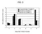
- the results are shown in Fig. 3 .
- the horizontal axis represents the number that denotes the analysis target regions, and the vertical axis represents the displacement (mm) in the Z direction at point A.
- the analysis target region 6 has the largest influence in Conventional Example, whereas the analysis target region 2 has the largest influence in Inventive Examples 1 and 2.
- each of the analysis target regions 2 and 6 was notched in a triangular shape at the flange, and a comparison was made. With a notch, since a deformation around the notch does not affect the other portions, it is possible to realize an effect similar to that in the case where the stress is removed.
- the analysis target region 6 has the largest influence in Conventional Example. It seems that, since the analysis target region 6 has a relatively complex shape and has a large residual stress after the springback, removing the residual stress at this analysis target region has a noticeable influence. Also, in the bending process, since the analysis target regions 4 to 6 are farther from the bend lines to which plastic deformation is applied, it seems that the influence of the analysis target region 6 is overestimated in Conventional Example.
Landscapes
- Engineering & Computer Science (AREA)
- Physics & Mathematics (AREA)
- Theoretical Computer Science (AREA)
- General Physics & Mathematics (AREA)
- General Engineering & Computer Science (AREA)
- Computer Hardware Design (AREA)
- Evolutionary Computation (AREA)
- Geometry (AREA)
- Mechanical Engineering (AREA)
- Shaping Metal By Deep-Drawing, Or The Like (AREA)
- Investigating Strength Of Materials By Application Of Mechanical Stress (AREA)
Abstract
Description
- This invention relates to a method for press forming analysis, and particularly to a method that quickly and accurately analyzes a degree of influence of stress in each region of a press-formed part on the springback.
- To realize the weight saving of an automobile, application of high-strength steel sheets to automobile parts has been expanded in recent years. Since the degree of an elastic recovery (hereinafter referred to as a springback, or may be abbreviated as SB) of high strength steel sheets after a press forming is greater than that of mild steel sheets, it is difficult to ensure accuracy of dimensions of parts. Therefore, until an acceptable dimensional accuracy is achieved, a repeated correction of a shape of press die and springback compensation of die are required.
- To reduce the burden for such correction of a press die, techniques for estimating the amount of springback at the press die design stage have been demanded, and analysis systems for the estimation have been developed.
- The analysis method involves the following stages:
- (1) analysis of the deformation, stress, and strain of a part under the restraint by a press die; and
- (2) analysis of the springback after the release from the restraint by the press die.
- Note that the analysis in stage (1) is performed by using a finite element method, and the analysis in stage (2) is performed by using a springback theoretical formula or a finite element method.
- The springback is known to be caused by an uneven distribution of residual stress accumulated in a formed part before the formed part is released from a press die. Conventionally, estimation using a numerical analysis method, such as a finite element method, has been performed. However, it has been difficult to estimate which region of the formed part has residual stress having a dominant influence on the springback.
- For example,
Patent Literatures -
Patent Literature 1 discloses a method of calculating how a value, which is defined to describe the springback, changes when a distribution of residual stress in a specific region of a press-formed part changes, and estimating an influence of the distribution of residual stress in the specific region on the springback. - PTL 1: Japanese Unexamined Patent Application Publication No.
2007-229724 - The method of changing stress disclosed in
Patent Literature 1 removes or changes the stress by only considering the stress before releasing the press-formed part from a press die. Then, a springback analysis is performed and compared with a case that the stress is not changed to examine an influence of the change of the stress. - However, even after a press-formed part is released from a press die, that is, even after the springback, the stress remains in the press-formed part. Therefore, when the influence is examined by only considering the stress before releasing the press-formed part from a press die, it may be difficult to accurately evaluate the influence of the stress in each region of the press-formed part.
- This invention has been made to solve the problems described above. An object of this invention is to determine, by changing the stress before the release from a press die, a degree of influence of stress in each region of a press-formed part on the springback by considering a distribution of stress (residual stress) after releasing the press-formed part from a press die.
- This invention is summarized as follows.
- A first invention is a method for press forming analysis, including
- (1) calculating a data representing a shape of and a distribution of residual stress in a press-formed part before being released from a press die, and performing a coordinate transformation on a basis of the data before being released from the press die to calculate a distribution of stress (a) before being released from the press die in a local coordinate system;
- (2) performing a springback analysis on a basis of the data before being released from the press die, wherein the performing of the springback analysis includes: (i) calculating a distribution of residual stress in the press-formed part after being released from the press die and performing the coordinate transformation to calculate a distribution of residual stress (b) in the press-formed part in the local coordinate system; and (ii) calculating a first shape data (d) of the press-formed part after being released from the press die;
- (3) calculating a difference (a - b) between the distributions of stress (a) and (b) as a springback effective stress (SB effective stress), performing a coordinate transformation to calculate a distribution of SB effective stress in a global coordinate system, changing or removing the SB effective stress in an analysis target region in the distribution of SB effective stress to calculate a second distribution of SB effective stress in the press-formed part, and performing the springback analysis to calculate a second shape data (c) of the press-formed part after being released from the press die; and
- (4) calculating a difference (c - d) between the second shape data (c) and the first shape data (d) to determine a degree of influence of the analysis target region on the overall shape.
- A second invention is a method for press forming analysis, including
- (1) calculating a data representing a shape of and a distribution of residual stress in a press-formed part before being released from a press die, and performing a coordinate transformation on a basis of the data before being released from the press die to calculate a distribution of stress (a) before being released from the press die in a local coordinate system;
- (2) performing a springback analysis on a basis of the data before being released from the press die, wherein the performing of the springback analysis includes: (i) calculating a distribution of residual stress in the press-formed part after being released from the press die and performing the coordinate transformation to calculate a distribution of residual stress (b) in the press-formed part in the local coordinate system; and (ii) calculating a first shape data (d) of the press-formed part after being released from the press die;
- (3) calculating a difference (a - b) between the distributions of stress (a) and (b) as a springback effective stress (SB effective stress), performing a coordinate transformation to calculate a distribution of SB effective stress in a global coordinate system, removing the SB effective stress in an analysis target region in the distribution of SB effective stress to calculate a second distribution of SB effective stress (X) in the press-formed part;
- (4) assigning the distribution of residual stress (b) in the local coordinate system to the shape of the press-formed part before being released from the press die to calculate an equivalent of residual stress in the local coordinate system, and performing the coordinate transformation to calculate an equivalent of residual stress (Y) in the press-formed part in the global coordinate system;
- (5) adding the equivalent of residual stress (Y) in the press-formed part to the second distribution of SB effective stress (X) in the press-formed part to calculate a second distribution of stress, performing the springback analysis to calculate a third shape data (c) of the press-formed part after being released from the press die; and
- (6) calculating a difference (c - d) between the third shape data (c) and the first shape data (d) to determine a degree of influence of the analysis target region on the overall shape.
- It is possible to appropriately evaluate an influence of the stress in an analysis target region on the springback without overestimating or underestimating the stress that actually contributes to the springback. By setting a local coordinate system, it is possible to evaluate an influence of a specific component of the stress by only removing the component. The analysis can be used to examine measures to reduce the springback.
-
- [
Fig. 1] Fig. 1 is a general view of a front body inner pillar subjected to SB analysis. - [
Fig. 2] Fig. 2 illustrates SB analysis target regions of the front body inner pillar. - [
Fig. 3] Fig. 3 illustrates an analysis result. - [
Fig. 4] Fig. 4 is a flowchart of a first embodiment. - [
Fig. 5] Fig. 5 is a flowchart of a second embodiment. - A first embodiment of this invention will be described with reference to a drawing.
-
Fig. 4 is a flowchart illustrating a procedure of a method for press forming analysis according to the first embodiment of a method for press forming analysis of this invention. The first embodiment is an analysis method that focuses only on a springback effective stress. That is, the first embodiment changes or removes the springback effective stress in a springback analysis target region, performs a springback analysis, and makes a comparison with a shape of the press-formed part after the release. Thus, an influence of stress in the springback analysis target region is evaluated. - An analytical calculation in the method for press forming analysis illustrated in
Fig. 4 is performed by using a finite element method (FEM) analysis system. - S1: First, in step S1, a distribution of stress in a press-formed part before the release from a press die is determined.
- S2: In step S2, the stress determined in step S1, which is expressed in the global coordinate system, is subjected to a coordinate transformation, and a distribution of stress (a) in a local coordinate system is determined. A springback causes a turning of the press-formed part after the release. Therefore, if a difference in the stress is determined by directly subtracting the stresses expressed in the global coordinate system, it is not possible to accurately determine the stress that contributes to the deformation. Thus, for respective finite elements to which the distribution of stress is given, a local coordinate system that does not change after the release is defined and the stress is subjected to a coordinate transformation. Then, a difference in the stress before and after the release is determined. This is a technique typically used in finite element analysis.
- The coordinate transformation of the stress is given by the following equations (1):
- [Numerical Expression 1]

where (l1, m1, n1), (l2, m2, n2), and (l3, m3, n3) are unit vectors of three orthogonal axes in the local coordinate system. - In a press forming simulation, the local coordinate system is defined typically by using a shell element having four or three nodes and no node in the thickness direction. Therefore, it is common to select, as the third axis of the coordinate system, the thickness direction, that is, the direction normal to a plane defined by four or three nodes. In the case of a four-node shell element, the four nodes are not necessarily in the same plane. Therefore, for example, (1) a direction obtained from an outer product of the diagonal lines may be defined as the thickness direction, or (2) a direction normal to an approximate plane may be defined as the thickness direction. As for the first axis and the second axis, for example, (1) a direction from the first node to the second node of the shell element may be defined as the first axis, or (2) the first axis and the second axis may be created from vectors of the diagonal lines.
- S3: A Springback analysis is performed on the basis of the distribution of stress determined in step S1.
- S4: A distribution of residual stress in the press-formed part after the release is determined.
- S5: A coordinate transformation from the global coordinate system to the local coordinate system is performed, and a distribution of residual stress (b) in the press-formed part after the release in the local coordinate system is determined.
- S6: Shape data (d) of the press-formed part after the release is determined from the springback analysis performed in step S3.
- S7: A difference (a - b) between the distribution of stress (a) before the release and the distribution of residual stress (b) after the release, which is defined as a springback effective stress (hereinafter referred to as SB effective stress), is determined.
- S8: A coordinate transformation from the local coordinate system to the global coordinate system is performed, and a distribution of SB effective stress in the global coordinate system is determined.
- S9: SB effective stress in an analysis target region is changed or removed.
- S10: A distribution of SB effective stress in the press-formed part after the change or removal of the SB effective stress in the analysis target region is determined.
- S11: A springback analysis is performed on the basis of the distribution of stress determined in step S10.
- S12: Shape data (c) of the press-formed part after the release is determined.
- S13: A difference (c - d) between the shape data (c) and the shape data (d) is calculated, and a degree of influence of the SB analysis target region on the overall shape is evaluated.
- A second embodiment of this invention will be described with reference to a drawing.
-
Fig. 5 is a flowchart illustrating a procedure of a method for press forming analysis according to the second embodiment of the method for press forming analysis of this invention. - The second embodiment is an analysis method that adds the residual stress in the local coordinate system to the distribution of the springback effective stress in the local coordinate system determined by the partial change or removal of the springback effective stress determined in the first embodiment, and transforms the obtained distribution of stress into the global coordinate system. Then, performs a springback analysis, and makes a comparison with a shape of the press-formed part after the release. Thus, an influence of stress in the springback analysis target region is evaluated.
- An analytical calculation in the method for press forming analysis illustrated in
Fig. 5 is performed by using a finite element method (FEM) analysis system. - S21: First, in step S21, a distribution of stress in a press-formed part before the release is determined.
- S22: In step S22, a local coordinate system that does not change after the release is defined. Then, the stress determined in step S21, which is expressed in the global coordinate system, is subjected to a coordinate transformation, and a distribution of stress (a) in the local coordinate system is determined. The method for determining the local coordinate system is the same as that in the first embodiment and thus is not described here.
- S23: A Springback analysis is performed on the basis of the distribution of stress determined in step S21.
- S24: A distribution of residual stress in the press-formed part after the release is determined.
- S25: A coordinate transformation from the global coordinate system to the local coordinate system is performed, and a distribution of residual stress (b) in the press-formed part after the release in the local coordinate system is determined.
- S26: Shape data (d) of the press-formed part after the release is determined from the springback analysis performed in step S23.
- S27: A difference (a - b) between the distribution of stress (a) before the release and the distribution of residual stress (b) after the release, which is defined as the springback effective stress (hereinafter referred to as SB effective stress), is determined.
- S28: A coordinate transformation from the local coordinate system to the global coordinate system is performed, and a distribution of SB effective stress in the global coordinate system is determined.
- S29: SB effective stress in an analysis target region is changed or removed.
- S30: A distribution of SB effective stress (X) in the press-formed part after the change or removal of the SB effective stress in the analysis target region is determined.
- S31: The stress (b) is assigned to the shape of the press-formed part before the release.
- S32: An equivalent of residual stress in the local coordinate system is determined.
- S33: The transformation to the global coordinate system is performed, and an equivalent of residual stress (Y) in the press-formed part in the global coordinate system is determined.
- S34: The equivalent of residual stress (Y) is added to the distribution of SB effective stress (X) to calculate a distribution of stress.
- S35: A Springback analysis is performed.
- S36: Shape data (c) of the press-formed part after the release is determined.
- S37: A difference (c - d) between the shape data (c) and the shape data (d) is calculated, and a degree of influence of the SB analysis target region on the overall shape is evaluated.
- As an example of the method for press forming analysis according to this invention, press forming of a front body inner pillar part will be described.
-
Fig. 1 illustrates a general shape of the part. A 980 MPa grade high-strength cold-rolled steel sheet with a thickness of 1.6 mm is press-formed using a die and trimmed. And the press-formed part is subjected to bending, and shaped into the front body inner pillar part. In the process of bending, the steel sheet is bent along bend lines illustrated inFig. 1 . - The press forming analysis analyzed a degree of influence of stress in each of the
analysis target regions 1 to 6 illustrated inFig. 2 on the forming of the front body inner pillar part illustrated inFig. 1 . - The analysis was performed by using a commercially available finite element method (FEM) analysis system in accordance with the steps illustrated in
Figs. 4 and5 . Specifically, after the process of bending, the stress in each of the regions (1 to 6) illustrated inFig. 2 was removed, and influences on displacements in the Z direction at points A and B was examined. Normally (i.e., when the stress in each region is not removed), displacements in the Z direction after the springback analysis is -16.5 mm at point A and -9.7 mm at point B, respectively. Conventional Example (Patent Literature 1) removed the entire stress in each analysis target region (one of 1 to 6) and performed the springback calculation. Inventive Example 1 extracted only SB effective stress according to this invention (in step S8 ofFig. 4 ), removed SB effective stress in each analysis target region (one of 1 to 6) (in step S9 ofFig. 4 ), and performed the springback calculation (in step S11 ofFig. 4 ). Inventive Example 2 removed SB effective stress in each analysis target region (one of 1 to 6) (in step S29 ofFig. 5 ), and performed the springback calculation (in step S35 ofFig. 5 ). - The results are shown in
Fig. 3 . The horizontal axis represents the number that denotes the analysis target regions, and the vertical axis represents the displacement (mm) in the Z direction at point A. As shown, theanalysis target region 6 has the largest influence in Conventional Example, whereas theanalysis target region 2 has the largest influence in Inventive Examples 1 and 2. - To specifically verify the results of factor analysis, each of the
analysis target regions - When the
analysis target region 6 was notched, point A was raised by 1.2 mm, whereas when theanalysis target region 2 was notched, point A was raised by 4.3 mm. This shows that theanalysis target region 2 has a larger influence, and that the factor analyses performed in Inventive Examples 1 and 2 are better than that performed in Conventional Example. - As described above, the
analysis target region 6 has the largest influence in Conventional Example. It seems that, since theanalysis target region 6 has a relatively complex shape and has a large residual stress after the springback, removing the residual stress at this analysis target region has a noticeable influence. Also, in the bending process, since theanalysis target regions 4 to 6 are farther from the bend lines to which plastic deformation is applied, it seems that the influence of theanalysis target region 6 is overestimated in Conventional Example. - 1 to 6: reference numerals denoting analysis target regions
Claims (2)
- A method for press forming analysis, comprising the steps of:(1) calculating a data representing a shape of and a distribution of residual stress in a press-formed part before being released from a press die, and performing a coordinate transformation on a basis of the data before being released from the press die to calculate a distribution of stress (a) before being released from the press die in a local coordinate system;(2) performing a springback analysis on a basis of the data before being released from the press die, wherein the performing of the springback analysis includes:(i) calculating a distribution of residual stress in the press-formed part after being released from the press die and performing the coordinate transformation to calculate a distribution of residual stress (b) in the press-formed part in the local coordinate system; and(ii) calculating a first shape data (d) of the press-formed part after being released from the press die;(3) calculating a difference (a - b) between the distributions of stress (a) and (b) as a springback effective stress (SB effective stress), performing a coordinate transformation to calculate a distribution of SB effective stress in a global coordinate system, changing or removing the SB effective stress in an analysis target region in the distribution of SB effective stress to calculate a second distribution of SB effective stress in the press-formed part, and performing the springback analysis to calculate a second shape data (c) of the press-formed part after being released from the press die; and(4) calculating a difference (c - d) between the second shape data (c) and the first shape data (d) to determine a degree of influence of the analysis target region on the overall shape.
- A method for press forming analysis, comprising the steps of:(1) calculating a data representing a shape of and a distribution of residual stress in a press-formed part before being released from a press die, and performing a coordinate transformation on a basis of the data before being released from the press die to calculate a distribution of stress (a) before being released from the press die in a local coordinate system;(2) performing a springback analysis on a basis of the data before being released from the press die, wherein the performing of the springback analysis includes:(i) calculating a distribution of residual stress in the press-formed part after being released from the press die and performing the coordinate transformation to calculate a distribution of residual stress (b) in the press-formed part in the local coordinate system; and(ii) calculating a first shape data (d) of the press-formed part after being released from the press die;(3) calculating a difference (a - b) between the distributions of stress (a) and (b) as a springback effective stress (SB effective stress), performing a coordinate transformation to calculate a distribution of SB effective stress in a global coordinate system, removing the SB effective stress in an analysis target region in the distribution of SB effective stress to calculate a second distribution of SB effective stress (X) in the press-formed part;(4) assigning the distribution of residual stress (b) in the local coordinate system to the shape of the press-formed part before being released from the press die to calculate an equivalent of residual stress in the local coordinate system, and performing the coordinate transformation to calculate an equivalent of residual stress (Y) in the press-formed part in the global coordinate system;(5) adding the equivalent of residual stress (Y) in the press-formed part to the second distribution of SB effective stress (X) in the press-formed part to calculate a second distribution of stress, performing the springback analysis to calculate a third shape data (c) of the press-formed part after being released from the press die; and(6) calculating a difference (c - d) between the third shape data (c) and the first shape data (d) to determine a degree of influence of the analysis target region on the overall shape.
Applications Claiming Priority (2)
| Application Number | Priority Date | Filing Date | Title |
|---|---|---|---|
| JP2011075778A JP5765014B2 (en) | 2011-03-30 | 2011-03-30 | Press forming analysis method |
| PCT/JP2012/058774 WO2012133867A1 (en) | 2011-03-30 | 2012-03-26 | Press forming analysis method |
Publications (3)
| Publication Number | Publication Date |
|---|---|
| EP2692454A1 true EP2692454A1 (en) | 2014-02-05 |
| EP2692454A4 EP2692454A4 (en) | 2014-10-08 |
| EP2692454B1 EP2692454B1 (en) | 2017-10-18 |
Family
ID=46931555
Family Applications (1)
| Application Number | Title | Priority Date | Filing Date |
|---|---|---|---|
| EP12763272.7A Active EP2692454B1 (en) | 2011-03-30 | 2012-03-26 | Press forming analysis method |
Country Status (7)
| Country | Link |
|---|---|
| US (1) | US9410855B2 (en) |
| EP (1) | EP2692454B1 (en) |
| JP (1) | JP5765014B2 (en) |
| KR (1) | KR101544464B1 (en) |
| CN (1) | CN103459058B (en) |
| MX (1) | MX2013011153A (en) |
| WO (1) | WO2012133867A1 (en) |
Cited By (1)
| Publication number | Priority date | Publication date | Assignee | Title |
|---|---|---|---|---|
| US11911816B2 (en) | 2019-02-01 | 2024-02-27 | Jfe Steel Corporation | Method for identifying variation factor portion of springback amount |
Families Citing this family (13)
| Publication number | Priority date | Publication date | Assignee | Title |
|---|---|---|---|---|
| CN103258095B (en) * | 2013-05-14 | 2015-10-07 | 西北工业大学 | The general milling force modeling method of flat-bottom end mill |
| CN106295055A (en) * | 2016-08-22 | 2017-01-04 | 南京埃斯顿自动化股份有限公司 | A kind of bender bending method that upper mold depth is carried out bending springback compensation |
| JP6519639B1 (en) | 2017-12-07 | 2019-05-29 | Jfeスチール株式会社 | Springback amount fluctuation factor site identification method |
| JP6852750B2 (en) | 2019-04-25 | 2021-03-31 | Jfeスチール株式会社 | Springback amount Dissociation factor Part identification method and device |
| JP6841295B2 (en) | 2019-05-22 | 2021-03-10 | Jfeスチール株式会社 | Springback amount divergence factor part identification method and device |
| WO2020262087A1 (en) * | 2019-06-26 | 2020-12-30 | 国立研究開発法人科学技術振興機構 | Stress and strain amount distribution display method, device, and program |
| JP7243657B2 (en) * | 2020-02-14 | 2023-03-22 | Jfeスチール株式会社 | Shape change prediction method for press-formed products |
| JP6888703B1 (en) * | 2020-02-14 | 2021-06-16 | Jfeスチール株式会社 | Method for predicting shape change of press-molded products |
| US12282717B2 (en) * | 2021-07-20 | 2025-04-22 | Ford Motor Company | Method and procedure for evaluation and compensation of springback |
| JP7698209B2 (en) * | 2021-12-23 | 2025-06-25 | 日本製鉄株式会社 | Analysis device, analysis method, manufacturing method, and program |
| KR20240171589A (en) | 2023-05-31 | 2024-12-09 | 광우알엔에이 주식회사 | Spring back correction method for aluminium bumper beam |
| KR20260010937A (en) * | 2024-07-15 | 2026-01-22 | 씨제이제일제당 (주) | Crystallizer modeling method and crystallizer modeling system |
| CN120480014B (en) * | 2025-07-17 | 2025-09-12 | 天津铭鑫汽车技术有限公司 | Automobile body stamping part forming method based on combined stamping |
Family Cites Families (8)
| Publication number | Priority date | Publication date | Assignee | Title |
|---|---|---|---|---|
| JP4631335B2 (en) * | 2004-07-21 | 2011-02-16 | Jfeスチール株式会社 | Method for determining the shape of a press mold |
| CA2613845C (en) * | 2005-06-30 | 2011-03-15 | Nippon Steel Corporation | Member designing method, member designing apparatus, computer program product, and computer-readable recording medium |
| JP4894294B2 (en) * | 2006-02-27 | 2012-03-14 | Jfeスチール株式会社 | Press forming analysis method |
| JP4739147B2 (en) * | 2006-08-28 | 2011-08-03 | トヨタ自動車株式会社 | Shape defect factor identification method, apparatus and program |
| CN103995927B (en) * | 2006-08-31 | 2017-01-04 | 新日铁住金株式会社 | Resilience countermeasure position specifying method and resilience countermeasure position specific device |
| JP4724626B2 (en) * | 2006-08-31 | 2011-07-13 | 新日本製鐵株式会社 | Springback occurrence cause identifying method, apparatus thereof, and program thereof |
| JP4410833B2 (en) * | 2007-12-25 | 2010-02-03 | 新日本製鐵株式会社 | Springback generation cause analysis method, apparatus, program and recording medium |
| CN101339574B (en) * | 2008-08-12 | 2010-06-16 | 江苏大学 | System and method for mold surface design of concrete mixing blade based on springback compensation |
-
2011
- 2011-03-30 JP JP2011075778A patent/JP5765014B2/en active Active
-
2012
- 2012-03-26 KR KR1020137026029A patent/KR101544464B1/en active Active
- 2012-03-26 MX MX2013011153A patent/MX2013011153A/en active IP Right Grant
- 2012-03-26 US US14/007,974 patent/US9410855B2/en active Active
- 2012-03-26 CN CN201280016493.7A patent/CN103459058B/en active Active
- 2012-03-26 WO PCT/JP2012/058774 patent/WO2012133867A1/en not_active Ceased
- 2012-03-26 EP EP12763272.7A patent/EP2692454B1/en active Active
Cited By (1)
| Publication number | Priority date | Publication date | Assignee | Title |
|---|---|---|---|---|
| US11911816B2 (en) | 2019-02-01 | 2024-02-27 | Jfe Steel Corporation | Method for identifying variation factor portion of springback amount |
Also Published As
| Publication number | Publication date |
|---|---|
| MX2013011153A (en) | 2013-11-01 |
| EP2692454A4 (en) | 2014-10-08 |
| US9410855B2 (en) | 2016-08-09 |
| JP5765014B2 (en) | 2015-08-19 |
| US20140019071A1 (en) | 2014-01-16 |
| CN103459058B (en) | 2015-11-25 |
| WO2012133867A1 (en) | 2012-10-04 |
| KR101544464B1 (en) | 2015-08-13 |
| JP2012206158A (en) | 2012-10-25 |
| CN103459058A (en) | 2013-12-18 |
| KR20130129457A (en) | 2013-11-28 |
| EP2692454B1 (en) | 2017-10-18 |
Similar Documents
| Publication | Publication Date | Title |
|---|---|---|
| EP2692454B1 (en) | Press forming analysis method | |
| US8126658B2 (en) | Shape defect factor identification method, device, and program | |
| EP2371464B1 (en) | Method, device, program and recording medium of analyzing cause of springback | |
| EP3991872B1 (en) | Springback variation cause analysis method | |
| JP4410833B2 (en) | Springback generation cause analysis method, apparatus, program and recording medium | |
| US7937183B2 (en) | Molded-component stress-strain curve estimation device | |
| EP2954961A1 (en) | Press-forming analysis method | |
| JP4724626B2 (en) | Springback occurrence cause identifying method, apparatus thereof, and program thereof | |
| EP4104945A1 (en) | Method for predicting change in shape of press-formed part | |
| EP3747566B1 (en) | Press-forming method, press-forming system, and press-formed product | |
| EP2933627A1 (en) | Spot welding section analysis method, spot welding section analysis program, storage medium and spot welding section analysis device | |
| EP3251769B1 (en) | Method for estimating surface shape defect generating regions, method for estimating surface shape defect source regions, surface shape defect generating region estimating device, shape defect source region estimating device, program and recording media | |
| EP4389314B1 (en) | Method of predicting shape change of press-formed product | |
| JP5131212B2 (en) | Material state estimation method | |
| JP4352658B2 (en) | Springback analysis method for press-formed products | |
| JP2012208884A (en) | Spring back factor analysis method in multi-process press molding | |
| EP4620590A1 (en) | Press-molding simulation analysis method, device and program, and press-molded product manufacturing method | |
| JP6323410B2 (en) | Structure partial analysis model generation apparatus and method, and structure collision analysis method using partial analysis model generated by structure partial analysis model generation method | |
| JP5210085B2 (en) | Deformation forecasting method | |
| EP4575437B1 (en) | Residual stress distribution calculation method, device and program | |
| JP2011164709A (en) | Method and device for generating spring back estimated shape of press forming die | |
| US20240256736A1 (en) | Method of measuring amount of automotive body deformation and program of measuring amount of automotive body deformation in crashworthiness analysis of automobile | |
| JP5059084B2 (en) | Design support program and design support apparatus | |
| JP2017199084A (en) | Structure design support device that can detect mechanical weak points of structures using inductive force | |
| Esener et al. | A Sensitivity analysis by using design of experiment and its application in stamping |
Legal Events
| Date | Code | Title | Description |
|---|---|---|---|
| PUAI | Public reference made under article 153(3) epc to a published international application that has entered the european phase |
Free format text: ORIGINAL CODE: 0009012 |
|
| 17P | Request for examination filed |
Effective date: 20131023 |
|
| AK | Designated contracting states |
Kind code of ref document: A1 Designated state(s): AL AT BE BG CH CY CZ DE DK EE ES FI FR GB GR HR HU IE IS IT LI LT LU LV MC MK MT NL NO PL PT RO RS SE SI SK SM TR |
|
| DAX | Request for extension of the european patent (deleted) | ||
| A4 | Supplementary search report drawn up and despatched |
Effective date: 20140910 |
|
| RIC1 | Information provided on ipc code assigned before grant |
Ipc: B21D 22/00 20060101AFI20140904BHEP Ipc: G06F 17/50 20060101ALI20140904BHEP |
|
| GRAP | Despatch of communication of intention to grant a patent |
Free format text: ORIGINAL CODE: EPIDOSNIGR1 |
|
| STAA | Information on the status of an ep patent application or granted ep patent |
Free format text: STATUS: GRANT OF PATENT IS INTENDED |
|
| INTG | Intention to grant announced |
Effective date: 20170510 |
|
| GRAS | Grant fee paid |
Free format text: ORIGINAL CODE: EPIDOSNIGR3 |
|
| GRAA | (expected) grant |
Free format text: ORIGINAL CODE: 0009210 |
|
| STAA | Information on the status of an ep patent application or granted ep patent |
Free format text: STATUS: THE PATENT HAS BEEN GRANTED |
|
| AK | Designated contracting states |
Kind code of ref document: B1 Designated state(s): AL AT BE BG CH CY CZ DE DK EE ES FI FR GB GR HR HU IE IS IT LI LT LU LV MC MK MT NL NO PL PT RO RS SE SI SK SM TR |
|
| REG | Reference to a national code |
Ref country code: GB Ref legal event code: FG4D |
|
| REG | Reference to a national code |
Ref country code: CH Ref legal event code: EP |
|
| REG | Reference to a national code |
Ref country code: AT Ref legal event code: REF Ref document number: 937496 Country of ref document: AT Kind code of ref document: T Effective date: 20171115 Ref country code: IE Ref legal event code: FG4D |
|
| REG | Reference to a national code |
Ref country code: DE Ref legal event code: R096 Ref document number: 602012038697 Country of ref document: DE |
|
| REG | Reference to a national code |
Ref country code: NL Ref legal event code: MP Effective date: 20171018 |
|
| REG | Reference to a national code |
Ref country code: LT Ref legal event code: MG4D |
|
| REG | Reference to a national code |
Ref country code: AT Ref legal event code: MK05 Ref document number: 937496 Country of ref document: AT Kind code of ref document: T Effective date: 20171018 |
|
| REG | Reference to a national code |
Ref country code: FR Ref legal event code: PLFP Year of fee payment: 7 |
|
| PG25 | Lapsed in a contracting state [announced via postgrant information from national office to epo] |
Ref country code: NL Free format text: LAPSE BECAUSE OF FAILURE TO SUBMIT A TRANSLATION OF THE DESCRIPTION OR TO PAY THE FEE WITHIN THE PRESCRIBED TIME-LIMIT Effective date: 20171018 |
|
| PG25 | Lapsed in a contracting state [announced via postgrant information from national office to epo] |
Ref country code: NO Free format text: LAPSE BECAUSE OF FAILURE TO SUBMIT A TRANSLATION OF THE DESCRIPTION OR TO PAY THE FEE WITHIN THE PRESCRIBED TIME-LIMIT Effective date: 20180118 Ref country code: FI Free format text: LAPSE BECAUSE OF FAILURE TO SUBMIT A TRANSLATION OF THE DESCRIPTION OR TO PAY THE FEE WITHIN THE PRESCRIBED TIME-LIMIT Effective date: 20171018 Ref country code: LT Free format text: LAPSE BECAUSE OF FAILURE TO SUBMIT A TRANSLATION OF THE DESCRIPTION OR TO PAY THE FEE WITHIN THE PRESCRIBED TIME-LIMIT Effective date: 20171018 Ref country code: SE Free format text: LAPSE BECAUSE OF FAILURE TO SUBMIT A TRANSLATION OF THE DESCRIPTION OR TO PAY THE FEE WITHIN THE PRESCRIBED TIME-LIMIT Effective date: 20171018 Ref country code: ES Free format text: LAPSE BECAUSE OF FAILURE TO SUBMIT A TRANSLATION OF THE DESCRIPTION OR TO PAY THE FEE WITHIN THE PRESCRIBED TIME-LIMIT Effective date: 20171018 |
|
| PG25 | Lapsed in a contracting state [announced via postgrant information from national office to epo] |
Ref country code: HR Free format text: LAPSE BECAUSE OF FAILURE TO SUBMIT A TRANSLATION OF THE DESCRIPTION OR TO PAY THE FEE WITHIN THE PRESCRIBED TIME-LIMIT Effective date: 20171018 Ref country code: AT Free format text: LAPSE BECAUSE OF FAILURE TO SUBMIT A TRANSLATION OF THE DESCRIPTION OR TO PAY THE FEE WITHIN THE PRESCRIBED TIME-LIMIT Effective date: 20171018 Ref country code: BG Free format text: LAPSE BECAUSE OF FAILURE TO SUBMIT A TRANSLATION OF THE DESCRIPTION OR TO PAY THE FEE WITHIN THE PRESCRIBED TIME-LIMIT Effective date: 20180118 Ref country code: GR Free format text: LAPSE BECAUSE OF FAILURE TO SUBMIT A TRANSLATION OF THE DESCRIPTION OR TO PAY THE FEE WITHIN THE PRESCRIBED TIME-LIMIT Effective date: 20180119 Ref country code: IS Free format text: LAPSE BECAUSE OF FAILURE TO SUBMIT A TRANSLATION OF THE DESCRIPTION OR TO PAY THE FEE WITHIN THE PRESCRIBED TIME-LIMIT Effective date: 20180218 Ref country code: RS Free format text: LAPSE BECAUSE OF FAILURE TO SUBMIT A TRANSLATION OF THE DESCRIPTION OR TO PAY THE FEE WITHIN THE PRESCRIBED TIME-LIMIT Effective date: 20171018 Ref country code: LV Free format text: LAPSE BECAUSE OF FAILURE TO SUBMIT A TRANSLATION OF THE DESCRIPTION OR TO PAY THE FEE WITHIN THE PRESCRIBED TIME-LIMIT Effective date: 20171018 |
|
| REG | Reference to a national code |
Ref country code: DE Ref legal event code: R097 Ref document number: 602012038697 Country of ref document: DE |
|
| PG25 | Lapsed in a contracting state [announced via postgrant information from national office to epo] |
Ref country code: DK Free format text: LAPSE BECAUSE OF FAILURE TO SUBMIT A TRANSLATION OF THE DESCRIPTION OR TO PAY THE FEE WITHIN THE PRESCRIBED TIME-LIMIT Effective date: 20171018 Ref country code: EE Free format text: LAPSE BECAUSE OF FAILURE TO SUBMIT A TRANSLATION OF THE DESCRIPTION OR TO PAY THE FEE WITHIN THE PRESCRIBED TIME-LIMIT Effective date: 20171018 Ref country code: SK Free format text: LAPSE BECAUSE OF FAILURE TO SUBMIT A TRANSLATION OF THE DESCRIPTION OR TO PAY THE FEE WITHIN THE PRESCRIBED TIME-LIMIT Effective date: 20171018 Ref country code: CZ Free format text: LAPSE BECAUSE OF FAILURE TO SUBMIT A TRANSLATION OF THE DESCRIPTION OR TO PAY THE FEE WITHIN THE PRESCRIBED TIME-LIMIT Effective date: 20171018 |
|
| PLBE | No opposition filed within time limit |
Free format text: ORIGINAL CODE: 0009261 |
|
| STAA | Information on the status of an ep patent application or granted ep patent |
Free format text: STATUS: NO OPPOSITION FILED WITHIN TIME LIMIT |
|
| PG25 | Lapsed in a contracting state [announced via postgrant information from national office to epo] |
Ref country code: SM Free format text: LAPSE BECAUSE OF FAILURE TO SUBMIT A TRANSLATION OF THE DESCRIPTION OR TO PAY THE FEE WITHIN THE PRESCRIBED TIME-LIMIT Effective date: 20171018 Ref country code: IT Free format text: LAPSE BECAUSE OF FAILURE TO SUBMIT A TRANSLATION OF THE DESCRIPTION OR TO PAY THE FEE WITHIN THE PRESCRIBED TIME-LIMIT Effective date: 20171018 Ref country code: RO Free format text: LAPSE BECAUSE OF FAILURE TO SUBMIT A TRANSLATION OF THE DESCRIPTION OR TO PAY THE FEE WITHIN THE PRESCRIBED TIME-LIMIT Effective date: 20171018 Ref country code: PL Free format text: LAPSE BECAUSE OF FAILURE TO SUBMIT A TRANSLATION OF THE DESCRIPTION OR TO PAY THE FEE WITHIN THE PRESCRIBED TIME-LIMIT Effective date: 20171018 |
|
| 26N | No opposition filed |
Effective date: 20180719 |
|
| REG | Reference to a national code |
Ref country code: CH Ref legal event code: PL |
|
| PG25 | Lapsed in a contracting state [announced via postgrant information from national office to epo] |
Ref country code: MC Free format text: LAPSE BECAUSE OF FAILURE TO SUBMIT A TRANSLATION OF THE DESCRIPTION OR TO PAY THE FEE WITHIN THE PRESCRIBED TIME-LIMIT Effective date: 20171018 Ref country code: SI Free format text: LAPSE BECAUSE OF FAILURE TO SUBMIT A TRANSLATION OF THE DESCRIPTION OR TO PAY THE FEE WITHIN THE PRESCRIBED TIME-LIMIT Effective date: 20171018 |
|
| REG | Reference to a national code |
Ref country code: BE Ref legal event code: MM Effective date: 20180331 |
|
| REG | Reference to a national code |
Ref country code: IE Ref legal event code: MM4A |
|
| PG25 | Lapsed in a contracting state [announced via postgrant information from national office to epo] |
Ref country code: LU Free format text: LAPSE BECAUSE OF NON-PAYMENT OF DUE FEES Effective date: 20180326 |
|
| PG25 | Lapsed in a contracting state [announced via postgrant information from national office to epo] |
Ref country code: IE Free format text: LAPSE BECAUSE OF NON-PAYMENT OF DUE FEES Effective date: 20180326 |
|
| PG25 | Lapsed in a contracting state [announced via postgrant information from national office to epo] |
Ref country code: BE Free format text: LAPSE BECAUSE OF NON-PAYMENT OF DUE FEES Effective date: 20180331 Ref country code: LI Free format text: LAPSE BECAUSE OF NON-PAYMENT OF DUE FEES Effective date: 20180331 Ref country code: CH Free format text: LAPSE BECAUSE OF NON-PAYMENT OF DUE FEES Effective date: 20180331 |
|
| PGFP | Annual fee paid to national office [announced via postgrant information from national office to epo] |
Ref country code: GB Payment date: 20190320 Year of fee payment: 8 |
|
| PG25 | Lapsed in a contracting state [announced via postgrant information from national office to epo] |
Ref country code: MT Free format text: LAPSE BECAUSE OF NON-PAYMENT OF DUE FEES Effective date: 20180326 |
|
| PG25 | Lapsed in a contracting state [announced via postgrant information from national office to epo] |
Ref country code: TR Free format text: LAPSE BECAUSE OF FAILURE TO SUBMIT A TRANSLATION OF THE DESCRIPTION OR TO PAY THE FEE WITHIN THE PRESCRIBED TIME-LIMIT Effective date: 20171018 |
|
| PG25 | Lapsed in a contracting state [announced via postgrant information from national office to epo] |
Ref country code: HU Free format text: LAPSE BECAUSE OF FAILURE TO SUBMIT A TRANSLATION OF THE DESCRIPTION OR TO PAY THE FEE WITHIN THE PRESCRIBED TIME-LIMIT; INVALID AB INITIO Effective date: 20120326 Ref country code: PT Free format text: LAPSE BECAUSE OF FAILURE TO SUBMIT A TRANSLATION OF THE DESCRIPTION OR TO PAY THE FEE WITHIN THE PRESCRIBED TIME-LIMIT Effective date: 20171018 |
|
| PG25 | Lapsed in a contracting state [announced via postgrant information from national office to epo] |
Ref country code: MK Free format text: LAPSE BECAUSE OF NON-PAYMENT OF DUE FEES Effective date: 20171018 Ref country code: CY Free format text: LAPSE BECAUSE OF FAILURE TO SUBMIT A TRANSLATION OF THE DESCRIPTION OR TO PAY THE FEE WITHIN THE PRESCRIBED TIME-LIMIT Effective date: 20171018 |
|
| PG25 | Lapsed in a contracting state [announced via postgrant information from national office to epo] |
Ref country code: AL Free format text: LAPSE BECAUSE OF FAILURE TO SUBMIT A TRANSLATION OF THE DESCRIPTION OR TO PAY THE FEE WITHIN THE PRESCRIBED TIME-LIMIT Effective date: 20171018 |
|
| REG | Reference to a national code |
Ref country code: DE Ref legal event code: R082 Ref document number: 602012038697 Country of ref document: DE Representative=s name: HL KEMPNER PATENTANWAELTE, SOLICITORS (ENGLAND, DE Ref country code: DE Ref legal event code: R082 Ref document number: 602012038697 Country of ref document: DE Representative=s name: HL KEMPNER PATENTANWALT, RECHTSANWALT, SOLICIT, DE Ref country code: DE Ref legal event code: R082 Ref document number: 602012038697 Country of ref document: DE Representative=s name: HL KEMPNER PARTG MBB, DE |
|
| GBPC | Gb: european patent ceased through non-payment of renewal fee |
Effective date: 20200326 |
|
| PG25 | Lapsed in a contracting state [announced via postgrant information from national office to epo] |
Ref country code: GB Free format text: LAPSE BECAUSE OF NON-PAYMENT OF DUE FEES Effective date: 20200326 |
|
| PGFP | Annual fee paid to national office [announced via postgrant information from national office to epo] |
Ref country code: DE Payment date: 20260128 Year of fee payment: 15 |
|
| PGFP | Annual fee paid to national office [announced via postgrant information from national office to epo] |
Ref country code: FR Payment date: 20260209 Year of fee payment: 15 |