EP2692446A1 - Rotary drum apparatus comprising a rotary drum and at least one electric motor for driving the drum, with a stator extending against a part of circumference of the drum - Google Patents
Rotary drum apparatus comprising a rotary drum and at least one electric motor for driving the drum, with a stator extending against a part of circumference of the drum Download PDFInfo
- Publication number
- EP2692446A1 EP2692446A1 EP13179084.2A EP13179084A EP2692446A1 EP 2692446 A1 EP2692446 A1 EP 2692446A1 EP 13179084 A EP13179084 A EP 13179084A EP 2692446 A1 EP2692446 A1 EP 2692446A1
- Authority
- EP
- European Patent Office
- Prior art keywords
- drum
- longitudinal axis
- stator
- motor
- rotor
- Prior art date
- Legal status (The legal status is an assumption and is not a legal conclusion. Google has not performed a legal analysis and makes no representation as to the accuracy of the status listed.)
- Granted
Links
Images


Classifications
-
- B—PERFORMING OPERATIONS; TRANSPORTING
- B02—CRUSHING, PULVERISING, OR DISINTEGRATING; PREPARATORY TREATMENT OF GRAIN FOR MILLING
- B02C—CRUSHING, PULVERISING, OR DISINTEGRATING IN GENERAL; MILLING GRAIN
- B02C17/00—Disintegrating by tumbling mills, i.e. mills having a container charged with the material to be disintegrated with or without special disintegrating members such as pebbles or balls
- B02C17/18—Details
- B02C17/24—Driving mechanisms
-
- H—ELECTRICITY
- H02—GENERATION; CONVERSION OR DISTRIBUTION OF ELECTRIC POWER
- H02K—DYNAMO-ELECTRIC MACHINES
- H02K16/00—Machines with more than one rotor or stator
-
- H—ELECTRICITY
- H02—GENERATION; CONVERSION OR DISTRIBUTION OF ELECTRIC POWER
- H02K—DYNAMO-ELECTRIC MACHINES
- H02K41/00—Propulsion systems in which a rigid body is moved along a path due to dynamo-electric interaction between the body and a magnetic field travelling along the path
- H02K41/02—Linear motors; Sectional motors
- H02K41/025—Asynchronous motors
-
- H—ELECTRICITY
- H02—GENERATION; CONVERSION OR DISTRIBUTION OF ELECTRIC POWER
- H02K—DYNAMO-ELECTRIC MACHINES
- H02K7/00—Arrangements for handling mechanical energy structurally associated with dynamo-electric machines, e.g. structural association with mechanical driving motors or auxiliary dynamo-electric machines
- H02K7/14—Structural association with mechanical loads, e.g. with hand-held machine tools or fans
-
- H—ELECTRICITY
- H02—GENERATION; CONVERSION OR DISTRIBUTION OF ELECTRIC POWER
- H02K—DYNAMO-ELECTRIC MACHINES
- H02K2201/00—Specific aspects not provided for in the other groups of this subclass relating to the magnetic circuits
- H02K2201/15—Sectional machines
-
- H—ELECTRICITY
- H02—GENERATION; CONVERSION OR DISTRIBUTION OF ELECTRIC POWER
- H02K—DYNAMO-ELECTRIC MACHINES
- H02K2213/00—Specific aspects, not otherwise provided for and not covered by codes H02K2201/00 - H02K2211/00
- H02K2213/12—Machines characterised by the modularity of some components
Definitions
- the present invention relates to a rotary drum apparatus comprising a drum rotatable around a longitudinal axis and at least one motor for driving the drum in rotation around the longitudinal axis.
- Each drive motor comprises a stator and a rotor, the rotor comprising at least one ring portion extending substantially perpendicular to the longitudinal axis.
- the invention applies, in particular, to an ore crusher, the drum then being adapted to receive an ore to be crushed.
- a rotary drum apparatus of aforementioned type is known from US 3,555,329 .
- This apparatus is a cement mill comprising a drum around a longitudinal axis and a motor for driving the drum in rotation around the longitudinal axis.
- the motor comprises a rotor joined together with the drum, and a stator having a stator winding.
- the stator winding is adapted to generate a magnetic field driving the rotor in rotation.
- the stator is in the form of a revolution ring around the longitudinal axis.
- the stator surrounds perpendicular to the longitudinal axis, the rotor which is itself fixed to the periphery of the drum along a plane perpendicular to the longitudinal axis.
- the stator then extends against the entire circumference of the drum along a plane perpendicular to the longitudinal axis.
- the drum has a high-value diameter, generally between 5 meters and 12 meters, along the plane perpendicular to the longitudinal axis. This leads to significant operating losses when the drive motor is damaged and must be stopped in order to be repaired.
- the aim of the invention is to provide a rotary drum apparatus offering better reliability, while being less sensitive to vibrations of the drum and associated mechanical deformations.
- the invention relates to a rotary drum apparatus of aforementioned type, wherein the stator of each drive motor extends against a part of circumference of the drum perpendicular to the longitudinal axis.
- the rotary drum apparatus comprises one or several of the following characteristics, taken individually or according to all technically possible combinations: the part of circumference of the drum against which the stator extends has an angular sector of value less than 90°, preferably less than 60°, more preferably substantially equal to 30°; the apparatus comprises two motors for driving the drum in rotation around the longitudinal axis; the stators of both motors are significantly diametrically opposed with respect to the longitudinal axis, and the rotors of both motors comprise at least one ring joint with both motors, said ring being joined together with the drum and extending substantially perpendicularly to the longitudinal axis; each electric drive motor is a linear motor; each drive motor comprises several separate modules, distributed along the longitudinal axis, each module comprising a rotor element and a stator element, the rotor element comprising at least one ring portion extending substantially perpendicularly to the longitudinal axis and the stator element extending against only a part of circumference of the drum;
- a rotary drum apparatus 10 comprises a drum 12 rotatable around a longitudinal axis X, a retaining frame 14 of the drum 12, and at least one electric motor 16, 18 for driving the drum 12 in rotation around the longitudinal axis X.
- the rotary drum apparatus 10 comprises a first electric motor 16 and a second electric motor 18; both electric motors 16, 18 being adapted to drive the drum 12 in rotation around the longitudinal axis X.
- the rotary drum apparatus 10 is, for example, an ore crusher, and then the drum 12 is adapted to receive an ore to be crushed.
- the drum 12 is adapted to receive steel balls, in order to facilitate ore crushing.
- the drum 12 extends along the longitudinal axis X and has, perpendicularly to the longitudinal axis X, a maximum diameter Dmax, visible in Figure 1 , of value greater than 1 meter.
- the maximum diameter Dmax of the drum 12 preferably has a value greater than 2 meters, more preferably a value greater than 4 meters and even more preferably a value greater than 10 meters.
- the value of the maximum diameter Dmax of the drum 12 is, for example, between 5 meters and 12 meters.
- the drum 12 has a shape of revolution around the longitudinal axis X, and is for example in shape of a revolving cylinder around the axis X.
- the drum 12 has, at each of its ends along the longitudinal axis X, a narrowing for the insertion, respectively extraction of the ore.
- the ends of the drum 12, not shown for sake of simplicity in Figure 1 are supported by the retaining frame 14, particularly during rotation of the drum 12.
- the retaining frame 14 is adapted to hold the drum 12 by its ends both axially along the longitudinal axis X and radially along radial direction perpendicular to the longitudinal axis X.
- the retaining frame 14 is, for example, made of concrete.
- the first drive motor 16 comprises a first stator 20 and a first rotor 22.
- the first drive motor 16 is made in the form of first separate modules 24A, 24B, 24C, distributed along the longitudinal axis X.
- the second drive motor 18 comprises second stator 26 and second rotor 28.
- the second drive motor 18 is made in the form of second separate modules 30A, 30B, 30C, distributed along the longitudinal axis X.
- the first motor 16 and the second motor 18 are, for example, linear motors. These first and second linear motors 16, 18 form the induction machines. The first and second motors 16, 18 are then asynchronous motors. Each electric motor 16, 18 have an electrical power for example greater than 10MW.
- Both drive motors 16, 18 comprise, for example, the same number of separate modules 24A, 24B, 24C, 30A, 30B, 30C.
- the number of first separate modules 24A, 24B, 24C is equal to 3
- the number of second separate modules 30A, 30B, 30C is equal to 3.
- the first stator 20 and second stator 26 extends against a part of the circumference of the drum 12, perpendicularly to the longitudinal axis X, as shown in Figure 1 .
- the part of the circumference of the drum 12 against which extends the first stator 20 has a first angular sector ⁇ 1 around the longitudinal axis X
- the part of the circumference of the drum 12 against which extends second stator 26 has a second angular sector ⁇ 2 around the longitudinal axis X, as shown in Figure 1 .
- the first angular sector ⁇ 1 and the second angular sector ⁇ 2 have values less than 90°, preferably less than 60°, more significantly preferably equal to 30°.
- the first stator 20 and second stator 26 are substantially diametrically opposed with respect to the longitudinal axis X.
- the first stator 20 and the second stator 26 are, for example, fastened directly to the retaining frame 14.
- the rotor 22, 28 of each drive motor 16, 18 comprises at least one ring portion 32A, 32B, 32C extending substantially perpendicularly to the longitudinal axis X.
- the rotor 22, 28 of each drive motor is joined together with the drum 12.
- the rotors 22, 28 of both motors 16, 18 comprise a first ring 32A, a second ring 32B and a third ring 32C, the first 32A, second 32B and third 32C rings being joint with both motors 16, 18 and extending substantially perpendicularly to the longitudinal axis X.
- the first three modules 24A, 24B, 24C each comprise a respective first rotor member 33A, 33B, 33C and a respective first stator element 34A, 34B, 34C.
- the second modules 30, 30A, 30B, 30C each have a respective second rotor element 35A, 35B, 35C and a respective second stator member 36A, 36B, 36C.
- the first, second and third rings 32A, 32B, 32C are spaced from each other along the longitudinal axis X.
- the first, second and third rings 32A, 32B, 32C are joined together with the drum 12.
- the first, second and third rings 32A, 32B, 32C are fixed to the outer periphery of the drum 12, for example, using bolts and nuts.
- the first, second and third rings 32A, 32B, 32C are welded to the outer periphery of the drum 12.
- Each ring 32A, 32B, 32C has a thickness E along the longitudinal axis X, as shown in Fig 2 .
- the thickness E is of the order of a centimeter.
- Each ring 32A, 32B, 32C comprises, for example, several angular segments attached to each other as a result of others at outer periphery of the drum 12. Each segment has a respective angular sector, and the sum of angular sectors of different segments forming the ring 32A, 32B, 32C correspond to the angular sector of said ring 32A, 32B, 32C.
- Each ring 32A, 32B, 32C is made, for example, of a copper alloy. Alternatively, each ring 32A, 32B, 32C is made of an aluminum alloy.
- the first rotor elements 33A, 33B, 33C are, for example, formed respectively by the first ring 32A, the second ring 32B and the third ring 32C.
- the first stator elements 34A, 34B, 34C extend against part of circumference of the drum 12 perpendicularly to the longitudinal axis X, and the part of circumference of the drum 12 against which the first stator elements 34A, 34B, 34C extends corresponding to the first angular sector ⁇ 1 described previously.
- each first stator element 34A, 34B, 34C is substantially diametrically opposed to a second corresponding stator element 36A, 36B, 36C, with respect to the longitudinal axis X.
- the first set of stator elements 34A, 34B, 34C form the first stator 20 of the first motor.
- the number of first stator elements 34A, 34B, 34C is equal to the number of rings 32A, 32B, 32C forming the first rotor elements 33A, 33B, 33C.
- the second rotor elements 35A, 35B, 35C are formed by the first ring 32A, the second ring 32B, and the third ring 32C respectively.
- the first set of rotor elements 33A, 33B, 33C form the first rotor 22 and the set of second rotor elements 35A, 35B, 35C form the second rotor 28, the first rotor 22 and the second rotor 28 being joined in the embodiment of Figure 1 .
- the first ring 32A is joint with the respective first rotor element 33A and the second rotor element 35A of first and second motors 16, 18.
- the second ring 32B and third ring 32C are joint with the respective first rotor elements 33B, 33C and second rotor elements 35B, 35C of first and second electric motors 16, 18.
- the second stator elements 36A, 36B, 36C extend against a part of circumference of the drum 12, perpendicularly to the longitudinal axis X, and the part of circumference of the drum 12 against which the second stator elements 36A, 36B, 36C extends corresponds to the second angular sector ⁇ 2 described previously.
- the second set of stator elements 36A, 36B, 36C form the second stator 26 of the second motor.
- the number of second stator elements 36A, 36B, 36C is equal to the number of rings 32A, 32B, 32C forming the second rotor elements 35A, 35B, 35C.
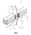
- Each stator element 34A, 34B, 34C, 36A, 36B, 36C comprises, in the known manner, a core 38 in which notches 40, and windings 42 housed in the notches 40 are arranged, as shown in Figure 2 .
- Figure 2 only the first stator element 34B is shown in detail for the sake of simplification.
- the notches 40 extend substantially perpendicularly to the longitudinal axis X, and the windings 42 are adapted to generate an axial flux along the longitudinal axis X when they are electrically powered (arrow F) .
- the notches 40 are parallel to each other.
- the notches 40 are not parallel and each are arranged along a respective radial direction, perpendicular to the longitudinal axis X. Such an arrangement of notches 40 allows to have sliding, between the stator 20, 26 and the rotor 22 of the corresponding motor 28, constant throughout the length of the rotor 22, 28 following the radial direction.
- the first stator elements 34A, 34B, 34C and the second stator elements 36A, 36B, 36C are electrically powered in order to generate an axial flux along the longitudinal axis X.
- Each axial flux then acts on the ring 32A, 32B, 32C respectively, and drives said rotor ring 32A, 32B, 32C following a direction perpendicular to the flux generated, in the known manner.
- the drive motor(s) 16, 18 of the rotary drum apparatus 10 are much simpler to manufacture than the drive motor of the state-of-the-art rotary drum apparatus, since the corresponding stator 20, 26 has dimensions are far less than those of the state - of - the - art stator, the stator 20, 26 does not extend over the entire circumference of the drum 12, but only on a part of said circumference.
- the motor(s) 16, 18 then depend very little on the size of the drum 12, particularly the value of its maximum diameter Dmax.
- the motor(s) 16, 18 are feasible in segmented form, while comprising several separate modules 24A, 24B, 24C, 30A, 30B, 30C. This further facilitates manufacturing of the motor (s) 16, 18.
- This realization in segmented form of the motor(s) 16, 18 also allows to provide operation redundancy, since in case of failure of a module among various modules 24A, 24B, 24C, 30A, 30B, 30C of the motor(s), it is sufficient to electrically isolate this faulty module, all while continuing to power supply the other modules. Then this allows to ensure continuity of operation of the rotary drum apparatus 10 in case of failure of a given module 24B, the stator elements 34A, 34C of other modules 24A, 24C being always capable of rotating the drum 12 around the longitudinal axis X through the magnetic effect exerted on the first and third ring 32A, 32C.
- stator(s) 20, 26 are adapted to generate an axial flux along the longitudinal axis X, and the motor(s) 16, 18 are then less disturbed by the radial displacements of the drum 12, these radial displacements being likely to be relatively large, of the order of centimeter, given the imbalance of the ore to be crushed.
- first and second stators 20, 26 allows to avoid asymmetry of mechanical torque exerted on the drum 12.
- FIG. 3 illustrates a second embodiment of the invention for which the elements similar to the first embodiment, described above, are identified by identical references, and are not described again.
- At least one ring portion 32A, 32B, 32C comprises a plurality of ferromagnetic elements 100 angularly offset relative to each other around the longitudinal axis.
- the ferromagnetic elements 100 are surrounded by a retaining part 102 made of an electrically conductive material.
- the corresponding ring portion 32A, 32B, 32C then forms a squirrel-cage rotor 22, 28.
- each ring 32A, 32B, 32C comprises plurality of ferromagnetic elements 100 surrounded by the retaining part 102.
- the first and second rotors 22, 28 are then squirrel-cage rotors.
- Each ferromagnetic element 100 has an angular sector a around the longitudinal axis X.
- the value of the angular sector a is smaller than those of the first and second angular sectors ⁇ 1, ⁇ 2.
- the value of the angular sector ⁇ is preferably less than ⁇ i/n, where n is an integer of value greater than or equal to 2, preferably greater than or equal to 4, and i is an index equal to 1 or 2 depending on whether the corresponding ring portion 32A, 32B, 32C belong to the first rotor part 22 or the second rotor 28.
- the retaining part 102 is, for example, made of a copper alloy. Alternatively, the retaining part 102 is made of an aluminum alloy. Alternatively, the holding portion 102 is made of an alloy of copper and aluminum.
- this second embodiment is similar to that of the first embodiment described above, and is not described again. According to the second embodiment, the advantages of this second embodiment are similar to those of the first embodiment described above.
Landscapes
- Engineering & Computer Science (AREA)
- Power Engineering (AREA)
- Food Science & Technology (AREA)
- Physics & Mathematics (AREA)
- Chemical & Material Sciences (AREA)
- Combustion & Propulsion (AREA)
- Electromagnetism (AREA)
- Connection Of Motors, Electrical Generators, Mechanical Devices, And The Like (AREA)
Abstract
Description
- The present invention relates to a rotary drum apparatus comprising a drum rotatable around a longitudinal axis and at least one motor for driving the drum in rotation around the longitudinal axis. Each drive motor comprises a stator and a rotor, the rotor comprising at least one ring portion extending substantially perpendicular to the longitudinal axis.
- The invention applies, in particular, to an ore crusher, the drum then being adapted to receive an ore to be crushed.
- A rotary drum apparatus of aforementioned type is known from
US 3,555,329 . This apparatus is a cement mill comprising a drum around a longitudinal axis and a motor for driving the drum in rotation around the longitudinal axis. The motor comprises a rotor joined together with the drum, and a stator having a stator winding. The stator winding is adapted to generate a magnetic field driving the rotor in rotation. - The stator is in the form of a revolution ring around the longitudinal axis. The stator surrounds perpendicular to the longitudinal axis, the rotor which is itself fixed to the periphery of the drum along a plane perpendicular to the longitudinal axis. The stator then extends against the entire circumference of the drum along a plane perpendicular to the longitudinal axis.
- However, such a rotary drum apparatus has reliability problems related to mechanical vibrations of the drum and associated mechanical deformations, the drum has a high-value diameter, generally between 5 meters and 12 meters, along the plane perpendicular to the longitudinal axis. This leads to significant operating losses when the drive motor is damaged and must be stopped in order to be repaired.
- Thus, the aim of the invention is to provide a rotary drum apparatus offering better reliability, while being less sensitive to vibrations of the drum and associated mechanical deformations.
- For this purpose, the invention relates to a rotary drum apparatus of aforementioned type, wherein the stator of each drive motor extends against a part of circumference of the drum perpendicular to the longitudinal axis.
- According to other advantageous aspects of the invention, the rotary drum apparatus comprises one or several of the following characteristics, taken individually or according to all technically possible combinations: the part of circumference of the drum against which the stator extends has an angular sector of value less than 90°, preferably less than 60°, more preferably substantially equal to 30°; the apparatus comprises two motors for driving the drum in rotation around the longitudinal axis; the stators of both motors are significantly diametrically opposed with respect to the longitudinal axis, and the rotors of both motors comprise at least one ring joint with both motors, said ring being joined together with the drum and extending substantially perpendicularly to the longitudinal axis; each electric drive motor is a linear motor; each drive motor comprises several separate modules, distributed along the longitudinal axis, each module comprising a rotor element and a stator element, the rotor element comprising at least one ring portion extending substantially perpendicularly to the longitudinal axis and the stator element extending against only a part of circumference of the drum; both drive motors comprise the same number of modules, each stator element of a motor being substantially diametrically against to the corresponding stator element of the other motor, relative to the longitudinal axis; each rotor element of a motor comprises a ring, said ring being joint with a corresponding rotor element of the other motor and extending substantially perpendicularly to the longitudinal axis; the drum has, perpendicular to the longitudinal axis, a maximum diameter of value greater than 1 meter, preferably greater than 2 meters, more preferably greater than 4 meters; at least one ring portion comprises plurality of ferromagnetic elements angularly offset with respect to each other around the longitudinal axis; and the apparatus is an ore crusher, the drum being adapted to receive an ore to be crushed.
- These characteristics and advantages of the invention will become apparent on reading the following description, given only as non-limiting example, and made in reference to the annexed drawings, wherein:
-
Figure 1 is a diagram of a rotating drum apparatus according to the invention; -
Figure 2 is a sectional view along the place inFigure 1 , and -
Figure 3 is a view similar to that ofFigure 2 according to second embodiment of the invention. - Conventionally, in this application, the term "substantially equal to" will express an equality relationship with plus or minus 5%.
- In
Figure 1 , arotary drum apparatus 10 comprises adrum 12 rotatable around a longitudinal axis X, a retaining frame 14 of thedrum 12, and at least oneelectric motor drum 12 in rotation around the longitudinal axis X. - In the embodiment of
Figure 1 , therotary drum apparatus 10 comprises a firstelectric motor 16 and a secondelectric motor 18; bothelectric motors drum 12 in rotation around the longitudinal axis X. - The
rotary drum apparatus 10 is, for example, an ore crusher, and then thedrum 12 is adapted to receive an ore to be crushed. In addition, thedrum 12 is adapted to receive steel balls, in order to facilitate ore crushing. - The
drum 12 extends along the longitudinal axis X and has, perpendicularly to the longitudinal axis X, a maximum diameter Dmax, visible inFigure 1 , of value greater than 1 meter. - The maximum diameter Dmax of the
drum 12 preferably has a value greater than 2 meters, more preferably a value greater than 4 meters and even more preferably a value greater than 10 meters. The value of the maximum diameter Dmax of thedrum 12 is, for example, between 5 meters and 12 meters. - The
drum 12 has a shape of revolution around the longitudinal axis X, and is for example in shape of a revolving cylinder around the axis X. - The
drum 12 has, at each of its ends along the longitudinal axis X, a narrowing for the insertion, respectively extraction of the ore. The ends of thedrum 12, not shown for sake of simplicity inFigure 1 , are supported by the retaining frame 14, particularly during rotation of thedrum 12. - The retaining frame 14 is adapted to hold the
drum 12 by its ends both axially along the longitudinal axis X and radially along radial direction perpendicular to the longitudinal axis X. The retaining frame 14 is, for example, made of concrete. - The
first drive motor 16 comprises afirst stator 20 and afirst rotor 22. In the embodiment ofFigure 1 , thefirst drive motor 16 is made in the form of firstseparate modules - The
second drive motor 18 comprisessecond stator 26 andsecond rotor 28. In the embodiment ofFigure 1 , thesecond drive motor 18 is made in the form of secondseparate modules - The
first motor 16 and thesecond motor 18 are, for example, linear motors. These first and secondlinear motors second motors electric motor - Both
drive motors separate modules Figure 1 , the number of firstseparate modules separate modules - The
first stator 20 andsecond stator 26 extends against a part of the circumference of thedrum 12, perpendicularly to the longitudinal axis X, as shown inFigure 1 . The part of the circumference of thedrum 12 against which extends thefirst stator 20 has a first angular sector θ1 around the longitudinal axis X, and the part of the circumference of thedrum 12 against which extendssecond stator 26 has a second angular sector θ2 around the longitudinal axis X, as shown inFigure 1 . - The first angular sector θ1 and the second angular sector θ2 have values less than 90°, preferably less than 60°, more significantly preferably equal to 30°.
- The
first stator 20 andsecond stator 26 are substantially diametrically opposed with respect to the longitudinal axis X. Thefirst stator 20 and thesecond stator 26 are, for example, fastened directly to the retaining frame 14. - The
rotor drive motor ring portion rotor drum 12. - In the embodiment of
Figure 1 , therotors motors first ring 32A, asecond ring 32B and athird ring 32C, the first 32A, second 32B and third 32C rings being joint with bothmotors - The first three
modules first rotor member first stator element - The
second modules second rotor element second stator member - The first, second and
third rings third rings drum 12. The first, second andthird rings drum 12, for example, using bolts and nuts. Alternatively, the first, second andthird rings drum 12. - Each
ring Fig 2 . The thickness E is of the order of a centimeter. - Each
ring drum 12. Each segment has a respective angular sector, and the sum of angular sectors of different segments forming thering said ring - Each
ring ring - The
first rotor elements first ring 32A, thesecond ring 32B and thethird ring 32C. - The
first stator elements drum 12 perpendicularly to the longitudinal axis X, and the part of circumference of thedrum 12 against which thefirst stator elements - In the embodiment of
Figure 1 , eachfirst stator element corresponding stator element - The first set of
stator elements first stator 20 of the first motor. The number offirst stator elements rings first rotor elements - The
second rotor elements first ring 32A, thesecond ring 32B, and thethird ring 32C respectively. - The first set of
rotor elements first rotor 22 and the set ofsecond rotor elements second rotor 28, thefirst rotor 22 and thesecond rotor 28 being joined in the embodiment ofFigure 1 . In other words, thefirst ring 32A is joint with the respective first rotor element 33A and thesecond rotor element 35A of first andsecond motors second ring 32B andthird ring 32C are joint with the respectivefirst rotor elements second rotor elements electric motors - The
second stator elements drum 12, perpendicularly to the longitudinal axis X, and the part of circumference of thedrum 12 against which thesecond stator elements - The second set of
stator elements second stator 26 of the second motor. The number ofsecond stator elements rings second rotor elements - Each
stator element notches 40, andwindings 42 housed in thenotches 40 are arranged, as shown inFigure 2 . InFigure 2 , only thefirst stator element 34B is shown in detail for the sake of simplification. - The
notches 40 extend substantially perpendicularly to the longitudinal axis X, and thewindings 42 are adapted to generate an axial flux along the longitudinal axis X when they are electrically powered (arrow F) . - In the embodiment of
Figure 2 , thenotches 40 are parallel to each other. - In an alternative not shown, the
notches 40 are not parallel and each are arranged along a respective radial direction, perpendicular to the longitudinal axis X. Such an arrangement ofnotches 40 allows to have sliding, between thestator rotor 22 of thecorresponding motor 28, constant throughout the length of therotor - During the operation of the
rotary drum apparatus 10, thefirst stator elements second stator elements - Each axial flux, represented by arrow F, then acts on the
ring rotor ring - The magnetic effect exerted on the rotor rings 32A, 32B, 32C by the first and
second stators drum 12 in rotation around the longitudinal axis X, thedrum 12 being supported at its ends by the retaining support 14. - Thus, the drive motor(s) 16, 18 of the
rotary drum apparatus 10 according to the invention are much simpler to manufacture than the drive motor of the state-of-the-art rotary drum apparatus, since the correspondingstator stator drum 12, but only on a part of said circumference. - The motor(s) 16, 18 then depend very little on the size of the
drum 12, particularly the value of its maximum diameter Dmax. - In addition, the motor(s) 16, 18 are feasible in segmented form, while comprising several
separate modules - This realization in segmented form of the motor(s) 16, 18 also allows to provide operation redundancy, since in case of failure of a module among
various modules rotary drum apparatus 10 in case of failure of a givenmodule 24B, thestator elements other modules drum 12 around the longitudinal axis X through the magnetic effect exerted on the first andthird ring - In addition, the stator(s) 20, 26 are adapted to generate an axial flux along the longitudinal axis X, and the motor(s) 16, 18 are then less disturbed by the radial displacements of the
drum 12, these radial displacements being likely to be relatively large, of the order of centimeter, given the imbalance of the ore to be crushed. - In addition, in the described embodiment, the arrangement diametrically opposed relative to the longitudinal axis X of first and
second stators drum 12. -
Figure 3 illustrates a second embodiment of the invention for which the elements similar to the first embodiment, described above, are identified by identical references, and are not described again. - According to the second embodiment, at least one
ring portion ferromagnetic elements 100 angularly offset relative to each other around the longitudinal axis. Theferromagnetic elements 100 are surrounded by a retainingpart 102 made of an electrically conductive material. Thecorresponding ring portion cage rotor - In the embodiment of
Figure 3 , eachring ferromagnetic elements 100 surrounded by the retainingpart 102. The first andsecond rotors - Each
ferromagnetic element 100 has an angular sector a around the longitudinal axis X. The value of the angular sector a is smaller than those of the first and second angular sectors θ1, θ2. The value of the angular sector α is preferably less than θi/n, where n is an integer of value greater than or equal to 2, preferably greater than or equal to 4, and i is an index equal to 1 or 2 depending on whether thecorresponding ring portion first rotor part 22 or thesecond rotor 28. - The retaining
part 102 is, for example, made of a copper alloy. Alternatively, the retainingpart 102 is made of an aluminum alloy. Alternatively, the holdingportion 102 is made of an alloy of copper and aluminum. - The operation of this second embodiment is similar to that of the first embodiment described above, and is not described again. According to the second embodiment, the advantages of this second embodiment are similar to those of the first embodiment described above.
- We also design the
rotary drum apparatus 10 according to the invention which offers better reliability, while being less sensitive to vibrations of the drum and associated mechanical deformations.
Claims (11)
- Rotary drum apparatus (10) comprising:a drum (12) rotatable around a longitudinal axis (X), andat least one electric motor (16,18) for driving the drum (12) in rotation around the longitudinal axis (X),each drive motor (16,18) comprising a stator (20,26) and a rotor (22,28), the rotor (22,28) comprising at least one ring portion (32A,32B,32C) joined together with the drum (12) and extending substantially perpendicularly to the longitudinal axis (X),characterized in that the stator (20,26) of each drive motor (16,18) extending against a part of circumference of the drum (12) perpendicularly to the longitudinal axis (X).
- Apparatus (10) as claimed in claim 1, characterized in that the part of circumference of the drum (12) against which the stator (20, 26) extends and has an angular sector (θ1,θ2) of value less than 90°, preferably less than 60°, more preferably substantially equal to 30°.
- Apparatus (10) as claimed in claim 1 or claim 2, characterized in that the apparatus (10) comprises two motors (16,18) for driving the drum (12) in rotation around the longitudinal axis (X) .
- Apparatus (10) as claimed in claim 3, characterized in that the stators (20 26) of both motors (16, 18) are substantially diametrically opposed with respect to the longitudinal axis (X), and the rotors (22,28) of both motors (16,18) comprise at least one ring (32A,32B,32C) joint with both motors (16,18), said ring (32A,32B,32C) being joint together with the drum (12) and extending substantially perpendicularly to the longitudinal axis (X).
- Apparatus (10) as claimed in any preceding claim, characterized in that each electric drive motor (16,18) is a linear motor.
- Apparatus (10) as claimed in any preceding claim, characterized in that each drive motor (16, 18) comprises a plurality of separate modules (24A, 24B, 24C, 30A, 30B, 30C) distributed along the longitudinal axis (X), each module (24A, ..., 30C) comprising a rotor member (33A,33B,33C,35A,35B,35C) and a stator element (34A,34B,34C,36A,36B,36C), the rotor member (33A, ..., 35C) comprising at least one ring portion (32A,32B,32C) extending substantially perpendicularly to the longitudinal axis (X) and the stator element (34A, ..., 36C) extending against a part of circumference of the drum (12).
- Apparatus (10) as claimed in any one of claims 3 to 6, characterized in that both drive motors (18,16) comprise the same number of modules (24A, ..., 24C, 30A, ..., 30C), each stator member (34A,34B,34C) of a motor being substantially diametrically against a corresponding stator element (36A,36B,36C) of the other motor, relative to the longitudinal axis (X).
- Apparatus (10) as claimed in claim 7, characterized in that each rotor member (33A, 33B, 33C) of a motor (16) comprises a ring (32A,32B,32C), said ring (32A, 32B,32C) being joint with a rotor member (35A,35B,35C) corresponding to the other motor (18) and extending substantially perpendicularly to the longitudinal axis (X).
- Apparatus (10) according to any preceding claim, wherein the drum (12) has, perpendicularly to the longitudinal axis (X), a maximum diameter (Dmax) of value greater than 1 meter, preferably greater than 2 meters, more preferably greater than 4 meters.
- Apparatus (10) as claimed in any preceding claim, characterized in that at least one ring portion (32A,32B,32C) comprises a plurality of ferromagnetic elements (100) angularly offset relative to each other around the longitudinal axis (X).
- Apparatus (10) as claimed in any preceding claim, characterized in that the apparatus (10) is an ore crusher, the drum (12) being adapted to receive an ore to be crushed.
Applications Claiming Priority (1)
| Application Number | Priority Date | Filing Date | Title |
|---|---|---|---|
| FR1257604A FR2994107B1 (en) | 2012-08-03 | 2012-08-03 | ROTARY DRUM APPARATUS COMPRISING A ROTARY DRUM AND AT LEAST ONE ELECTRIC DRUM DRIVE MOTOR, WITH A STATOR EXTENDING ONLY ONE PART OF THE CIRCUMFERENCE OF THE DRUM |
Publications (2)
| Publication Number | Publication Date |
|---|---|
| EP2692446A1 true EP2692446A1 (en) | 2014-02-05 |
| EP2692446B1 EP2692446B1 (en) | 2019-04-24 |
Family
ID=46963950
Family Applications (1)
| Application Number | Title | Priority Date | Filing Date |
|---|---|---|---|
| EP13179084.2A Active EP2692446B1 (en) | 2012-08-03 | 2013-08-02 | Rotary drum apparatus comprising a rotary drum and at least one electric motor for driving the drum, with a stator extending against a part of circumference of the drum |
Country Status (3)
| Country | Link |
|---|---|
| US (1) | US9387481B2 (en) |
| EP (1) | EP2692446B1 (en) |
| FR (1) | FR2994107B1 (en) |
Families Citing this family (1)
| Publication number | Priority date | Publication date | Assignee | Title |
|---|---|---|---|---|
| WO2012176359A1 (en) * | 2011-06-23 | 2012-12-27 | 株式会社ブリヂストン | Tire testing device |
Citations (5)
| Publication number | Priority date | Publication date | Assignee | Title |
|---|---|---|---|---|
| FR1334283A (en) * | 1961-09-26 | 1963-08-02 | Gen Electric Co Ltd | Improvements to grinding mills, pelletizers and similar apparatus |
| US3555329A (en) | 1968-05-27 | 1971-01-12 | Bbc Brown Boveri & Cie | Gearless drive for cement mill |
| US20030094524A1 (en) * | 2001-11-16 | 2003-05-22 | Scuccato Serge Louis | Grinding mill and methods for fabricating same |
| DE102007005131B3 (en) * | 2007-02-01 | 2008-01-31 | Siemens Ag | Ring motor as direct drive, particularly for ore mills or tube mills, comprises stator and rotor formed as rotary mill body, where stator has two different excitation systems and mill body has toothed structure |
| WO2012100818A1 (en) * | 2011-01-25 | 2012-08-02 | Siemens Aktiengesellschaft | Tube mill |
-
2012
- 2012-08-03 FR FR1257604A patent/FR2994107B1/en active Active
-
2013
- 2013-08-02 EP EP13179084.2A patent/EP2692446B1/en active Active
- 2013-08-02 US US13/957,837 patent/US9387481B2/en active Active
Patent Citations (5)
| Publication number | Priority date | Publication date | Assignee | Title |
|---|---|---|---|---|
| FR1334283A (en) * | 1961-09-26 | 1963-08-02 | Gen Electric Co Ltd | Improvements to grinding mills, pelletizers and similar apparatus |
| US3555329A (en) | 1968-05-27 | 1971-01-12 | Bbc Brown Boveri & Cie | Gearless drive for cement mill |
| US20030094524A1 (en) * | 2001-11-16 | 2003-05-22 | Scuccato Serge Louis | Grinding mill and methods for fabricating same |
| DE102007005131B3 (en) * | 2007-02-01 | 2008-01-31 | Siemens Ag | Ring motor as direct drive, particularly for ore mills or tube mills, comprises stator and rotor formed as rotary mill body, where stator has two different excitation systems and mill body has toothed structure |
| WO2012100818A1 (en) * | 2011-01-25 | 2012-08-02 | Siemens Aktiengesellschaft | Tube mill |
Also Published As
| Publication number | Publication date |
|---|---|
| FR2994107A1 (en) | 2014-02-07 |
| EP2692446B1 (en) | 2019-04-24 |
| US9387481B2 (en) | 2016-07-12 |
| US20140034767A1 (en) | 2014-02-06 |
| FR2994107B1 (en) | 2015-06-19 |
Similar Documents
| Publication | Publication Date | Title |
|---|---|---|
| JP5751747B2 (en) | Stator arrangement, generator and wind turbine | |
| JP5941484B2 (en) | Permanent magnet rotating electric machine | |
| US11018537B2 (en) | Method of construction for permanent magnet generator | |
| US9143014B2 (en) | Rotor, dynamo-electric machine having the rotor and rotor manufacturing method | |
| JP6323630B1 (en) | Two-axis integrated motor | |
| US9831743B2 (en) | Machine with two co-axial rotors | |
| US4453101A (en) | Amortisseur bar with improved interface between free conductor bars and amortisseur ring | |
| US20170047833A1 (en) | Rotary electrical machine | |
| CN108781010A (en) | Rotors for axial flux electromagnetic motors or generators with semi-embedded magnets and axial retaining means | |
| US20150333584A1 (en) | High speed brushless dc electric machine | |
| US7411330B2 (en) | Rotating electric machine | |
| EP3084937A2 (en) | Optimized synchronous reluctance motor assisted by permanent magnets | |
| US8569923B2 (en) | Rotating electric machine with interlocking inner and outer press plates | |
| EP2692446B1 (en) | Rotary drum apparatus comprising a rotary drum and at least one electric motor for driving the drum, with a stator extending against a part of circumference of the drum | |
| CN103867290A (en) | Turbocharger embedding an electrical machine with permanent magnets | |
| WO2014192609A1 (en) | Inner rotor brushless motor | |
| JP2013188075A (en) | Rotor of permanent magnet type rotary electrical machine | |
| US11258317B2 (en) | Synchronous generator | |
| EP3512082B1 (en) | Magnetic device suitable for use as a power generator or drive motor | |
| US9450470B2 (en) | Electric machine having two rotors and at least two bearings | |
| RU2382472C1 (en) | Rotor of high-speed electric machine (versions) | |
| CN1877966B (en) | Motor | |
| US20140125063A1 (en) | Electrical Generator | |
| US10044249B2 (en) | Rotary electric machine | |
| EP2677133A1 (en) | Turbocharger embedding an electrical machine with a dc coil |
Legal Events
| Date | Code | Title | Description |
|---|---|---|---|
| AK | Designated contracting states |
Kind code of ref document: A1 Designated state(s): AL AT BE BG CH CY CZ DE DK EE ES FI FR GB GR HR HU IE IS IT LI LT LU LV MC MK MT NL NO PL PT RO RS SE SI SK SM TR |
|
| AX | Request for extension of the european patent |
Extension state: BA ME |
|
| PUAI | Public reference made under article 153(3) epc to a published international application that has entered the european phase |
Free format text: ORIGINAL CODE: 0009012 |
|
| 17P | Request for examination filed |
Effective date: 20140731 |
|
| RBV | Designated contracting states (corrected) |
Designated state(s): AL AT BE BG CH CY CZ DE DK EE ES FI FR GB GR HR HU IE IS IT LI LT LU LV MC MK MT NL NO PL PT RO RS SE SI SK SM TR |
|
| GRAP | Despatch of communication of intention to grant a patent |
Free format text: ORIGINAL CODE: EPIDOSNIGR1 |
|
| STAA | Information on the status of an ep patent application or granted ep patent |
Free format text: STATUS: GRANT OF PATENT IS INTENDED |
|
| INTG | Intention to grant announced |
Effective date: 20181105 |
|
| RIN1 | Information on inventor provided before grant (corrected) |
Inventor name: PERMUY, ALFRED |
|
| GRAS | Grant fee paid |
Free format text: ORIGINAL CODE: EPIDOSNIGR3 |
|
| GRAA | (expected) grant |
Free format text: ORIGINAL CODE: 0009210 |
|
| STAA | Information on the status of an ep patent application or granted ep patent |
Free format text: STATUS: THE PATENT HAS BEEN GRANTED |
|
| AK | Designated contracting states |
Kind code of ref document: B1 Designated state(s): AL AT BE BG CH CY CZ DE DK EE ES FI FR GB GR HR HU IE IS IT LI LT LU LV MC MK MT NL NO PL PT RO RS SE SI SK SM TR |
|
| REG | Reference to a national code |
Ref country code: GB Ref legal event code: FG4D |
|
| REG | Reference to a national code |
Ref country code: CH Ref legal event code: EP |
|
| REG | Reference to a national code |
Ref country code: DE Ref legal event code: R096 Ref document number: 602013054219 Country of ref document: DE |
|
| REG | Reference to a national code |
Ref country code: AT Ref legal event code: REF Ref document number: 1123498 Country of ref document: AT Kind code of ref document: T Effective date: 20190515 Ref country code: IE Ref legal event code: FG4D |
|
| REG | Reference to a national code |
Ref country code: NL Ref legal event code: MP Effective date: 20190424 |
|
| REG | Reference to a national code |
Ref country code: LT Ref legal event code: MG4D |
|
| PG25 | Lapsed in a contracting state [announced via postgrant information from national office to epo] |
Ref country code: NL Free format text: LAPSE BECAUSE OF FAILURE TO SUBMIT A TRANSLATION OF THE DESCRIPTION OR TO PAY THE FEE WITHIN THE PRESCRIBED TIME-LIMIT Effective date: 20190424 |
|
| PG25 | Lapsed in a contracting state [announced via postgrant information from national office to epo] |
Ref country code: AL Free format text: LAPSE BECAUSE OF FAILURE TO SUBMIT A TRANSLATION OF THE DESCRIPTION OR TO PAY THE FEE WITHIN THE PRESCRIBED TIME-LIMIT Effective date: 20190424 Ref country code: ES Free format text: LAPSE BECAUSE OF FAILURE TO SUBMIT A TRANSLATION OF THE DESCRIPTION OR TO PAY THE FEE WITHIN THE PRESCRIBED TIME-LIMIT Effective date: 20190424 Ref country code: LT Free format text: LAPSE BECAUSE OF FAILURE TO SUBMIT A TRANSLATION OF THE DESCRIPTION OR TO PAY THE FEE WITHIN THE PRESCRIBED TIME-LIMIT Effective date: 20190424 Ref country code: HR Free format text: LAPSE BECAUSE OF FAILURE TO SUBMIT A TRANSLATION OF THE DESCRIPTION OR TO PAY THE FEE WITHIN THE PRESCRIBED TIME-LIMIT Effective date: 20190424 Ref country code: FI Free format text: LAPSE BECAUSE OF FAILURE TO SUBMIT A TRANSLATION OF THE DESCRIPTION OR TO PAY THE FEE WITHIN THE PRESCRIBED TIME-LIMIT Effective date: 20190424 Ref country code: SE Free format text: LAPSE BECAUSE OF FAILURE TO SUBMIT A TRANSLATION OF THE DESCRIPTION OR TO PAY THE FEE WITHIN THE PRESCRIBED TIME-LIMIT Effective date: 20190424 Ref country code: PT Free format text: LAPSE BECAUSE OF FAILURE TO SUBMIT A TRANSLATION OF THE DESCRIPTION OR TO PAY THE FEE WITHIN THE PRESCRIBED TIME-LIMIT Effective date: 20190824 Ref country code: NO Free format text: LAPSE BECAUSE OF FAILURE TO SUBMIT A TRANSLATION OF THE DESCRIPTION OR TO PAY THE FEE WITHIN THE PRESCRIBED TIME-LIMIT Effective date: 20190724 |
|
| PG25 | Lapsed in a contracting state [announced via postgrant information from national office to epo] |
Ref country code: LV Free format text: LAPSE BECAUSE OF FAILURE TO SUBMIT A TRANSLATION OF THE DESCRIPTION OR TO PAY THE FEE WITHIN THE PRESCRIBED TIME-LIMIT Effective date: 20190424 Ref country code: PL Free format text: LAPSE BECAUSE OF FAILURE TO SUBMIT A TRANSLATION OF THE DESCRIPTION OR TO PAY THE FEE WITHIN THE PRESCRIBED TIME-LIMIT Effective date: 20190424 Ref country code: GR Free format text: LAPSE BECAUSE OF FAILURE TO SUBMIT A TRANSLATION OF THE DESCRIPTION OR TO PAY THE FEE WITHIN THE PRESCRIBED TIME-LIMIT Effective date: 20190725 Ref country code: RS Free format text: LAPSE BECAUSE OF FAILURE TO SUBMIT A TRANSLATION OF THE DESCRIPTION OR TO PAY THE FEE WITHIN THE PRESCRIBED TIME-LIMIT Effective date: 20190424 Ref country code: BG Free format text: LAPSE BECAUSE OF FAILURE TO SUBMIT A TRANSLATION OF THE DESCRIPTION OR TO PAY THE FEE WITHIN THE PRESCRIBED TIME-LIMIT Effective date: 20190724 |
|
| REG | Reference to a national code |
Ref country code: AT Ref legal event code: MK05 Ref document number: 1123498 Country of ref document: AT Kind code of ref document: T Effective date: 20190424 |
|
| PG25 | Lapsed in a contracting state [announced via postgrant information from national office to epo] |
Ref country code: IS Free format text: LAPSE BECAUSE OF FAILURE TO SUBMIT A TRANSLATION OF THE DESCRIPTION OR TO PAY THE FEE WITHIN THE PRESCRIBED TIME-LIMIT Effective date: 20190824 |
|
| REG | Reference to a national code |
Ref country code: DE Ref legal event code: R097 Ref document number: 602013054219 Country of ref document: DE |
|
| PG25 | Lapsed in a contracting state [announced via postgrant information from national office to epo] |
Ref country code: RO Free format text: LAPSE BECAUSE OF FAILURE TO SUBMIT A TRANSLATION OF THE DESCRIPTION OR TO PAY THE FEE WITHIN THE PRESCRIBED TIME-LIMIT Effective date: 20190424 Ref country code: CZ Free format text: LAPSE BECAUSE OF FAILURE TO SUBMIT A TRANSLATION OF THE DESCRIPTION OR TO PAY THE FEE WITHIN THE PRESCRIBED TIME-LIMIT Effective date: 20190424 Ref country code: EE Free format text: LAPSE BECAUSE OF FAILURE TO SUBMIT A TRANSLATION OF THE DESCRIPTION OR TO PAY THE FEE WITHIN THE PRESCRIBED TIME-LIMIT Effective date: 20190424 Ref country code: AT Free format text: LAPSE BECAUSE OF FAILURE TO SUBMIT A TRANSLATION OF THE DESCRIPTION OR TO PAY THE FEE WITHIN THE PRESCRIBED TIME-LIMIT Effective date: 20190424 Ref country code: SK Free format text: LAPSE BECAUSE OF FAILURE TO SUBMIT A TRANSLATION OF THE DESCRIPTION OR TO PAY THE FEE WITHIN THE PRESCRIBED TIME-LIMIT Effective date: 20190424 Ref country code: DK Free format text: LAPSE BECAUSE OF FAILURE TO SUBMIT A TRANSLATION OF THE DESCRIPTION OR TO PAY THE FEE WITHIN THE PRESCRIBED TIME-LIMIT Effective date: 20190424 |
|
| PG25 | Lapsed in a contracting state [announced via postgrant information from national office to epo] |
Ref country code: IT Free format text: LAPSE BECAUSE OF FAILURE TO SUBMIT A TRANSLATION OF THE DESCRIPTION OR TO PAY THE FEE WITHIN THE PRESCRIBED TIME-LIMIT Effective date: 20190424 Ref country code: SM Free format text: LAPSE BECAUSE OF FAILURE TO SUBMIT A TRANSLATION OF THE DESCRIPTION OR TO PAY THE FEE WITHIN THE PRESCRIBED TIME-LIMIT Effective date: 20190424 |
|
| PLBE | No opposition filed within time limit |
Free format text: ORIGINAL CODE: 0009261 |
|
| STAA | Information on the status of an ep patent application or granted ep patent |
Free format text: STATUS: NO OPPOSITION FILED WITHIN TIME LIMIT |
|
| PG25 | Lapsed in a contracting state [announced via postgrant information from national office to epo] |
Ref country code: TR Free format text: LAPSE BECAUSE OF FAILURE TO SUBMIT A TRANSLATION OF THE DESCRIPTION OR TO PAY THE FEE WITHIN THE PRESCRIBED TIME-LIMIT Effective date: 20190424 |
|
| 26N | No opposition filed |
Effective date: 20200127 |
|
| PG25 | Lapsed in a contracting state [announced via postgrant information from national office to epo] |
Ref country code: SI Free format text: LAPSE BECAUSE OF FAILURE TO SUBMIT A TRANSLATION OF THE DESCRIPTION OR TO PAY THE FEE WITHIN THE PRESCRIBED TIME-LIMIT Effective date: 20190424 Ref country code: LI Free format text: LAPSE BECAUSE OF NON-PAYMENT OF DUE FEES Effective date: 20190831 Ref country code: MC Free format text: LAPSE BECAUSE OF FAILURE TO SUBMIT A TRANSLATION OF THE DESCRIPTION OR TO PAY THE FEE WITHIN THE PRESCRIBED TIME-LIMIT Effective date: 20190424 Ref country code: CH Free format text: LAPSE BECAUSE OF NON-PAYMENT OF DUE FEES Effective date: 20190831 Ref country code: LU Free format text: LAPSE BECAUSE OF NON-PAYMENT OF DUE FEES Effective date: 20190802 |
|
| REG | Reference to a national code |
Ref country code: BE Ref legal event code: MM Effective date: 20190831 |
|
| PG25 | Lapsed in a contracting state [announced via postgrant information from national office to epo] |
Ref country code: IE Free format text: LAPSE BECAUSE OF NON-PAYMENT OF DUE FEES Effective date: 20190802 |
|
| PG25 | Lapsed in a contracting state [announced via postgrant information from national office to epo] |
Ref country code: BE Free format text: LAPSE BECAUSE OF NON-PAYMENT OF DUE FEES Effective date: 20190831 |
|
| PG25 | Lapsed in a contracting state [announced via postgrant information from national office to epo] |
Ref country code: CY Free format text: LAPSE BECAUSE OF FAILURE TO SUBMIT A TRANSLATION OF THE DESCRIPTION OR TO PAY THE FEE WITHIN THE PRESCRIBED TIME-LIMIT Effective date: 20190424 |
|
| PG25 | Lapsed in a contracting state [announced via postgrant information from national office to epo] |
Ref country code: HU Free format text: LAPSE BECAUSE OF FAILURE TO SUBMIT A TRANSLATION OF THE DESCRIPTION OR TO PAY THE FEE WITHIN THE PRESCRIBED TIME-LIMIT; INVALID AB INITIO Effective date: 20130802 Ref country code: MT Free format text: LAPSE BECAUSE OF FAILURE TO SUBMIT A TRANSLATION OF THE DESCRIPTION OR TO PAY THE FEE WITHIN THE PRESCRIBED TIME-LIMIT Effective date: 20190424 |
|
| PG25 | Lapsed in a contracting state [announced via postgrant information from national office to epo] |
Ref country code: MK Free format text: LAPSE BECAUSE OF FAILURE TO SUBMIT A TRANSLATION OF THE DESCRIPTION OR TO PAY THE FEE WITHIN THE PRESCRIBED TIME-LIMIT Effective date: 20190424 |
|
| PGFP | Annual fee paid to national office [announced via postgrant information from national office to epo] |
Ref country code: DE Payment date: 20250724 Year of fee payment: 13 |
|
| PGFP | Annual fee paid to national office [announced via postgrant information from national office to epo] |
Ref country code: GB Payment date: 20250724 Year of fee payment: 13 |
|
| PGFP | Annual fee paid to national office [announced via postgrant information from national office to epo] |
Ref country code: FR Payment date: 20250725 Year of fee payment: 13 |