EP2692155B1 - Audio precompensation controller design using a variable set of support loudspeakers - Google Patents
Audio precompensation controller design using a variable set of support loudspeakers Download PDFInfo
- Publication number
- EP2692155B1 EP2692155B1 EP12872014.1A EP12872014A EP2692155B1 EP 2692155 B1 EP2692155 B1 EP 2692155B1 EP 12872014 A EP12872014 A EP 12872014A EP 2692155 B1 EP2692155 B1 EP 2692155B1
- Authority
- EP
- European Patent Office
- Prior art keywords
- loudspeaker
- controller
- loudspeakers
- audio
- audio precompensation
- Prior art date
- Legal status (The legal status is an assumption and is not a legal conclusion. Google has not performed a legal analysis and makes no representation as to the accuracy of the status listed.)
- Active
Links
Images


Classifications
-
- H—ELECTRICITY
- H04—ELECTRIC COMMUNICATION TECHNIQUE
- H04R—LOUDSPEAKERS, MICROPHONES, GRAMOPHONE PICK-UPS OR LIKE ACOUSTIC ELECTROMECHANICAL TRANSDUCERS; ELECTRIC HEARING AIDS; PUBLIC ADDRESS SYSTEMS
- H04R3/00—Circuits for transducers
- H04R3/04—Circuits for transducers for correcting frequency response
-
- H—ELECTRICITY
- H04—ELECTRIC COMMUNICATION TECHNIQUE
- H04S—STEREOPHONIC SYSTEMS
- H04S7/00—Indicating arrangements; Control arrangements, e.g. balance control
- H04S7/30—Control circuits for electronic adaptation of the sound field
- H04S7/301—Automatic calibration of stereophonic sound system, e.g. with test microphone
-
- H—ELECTRICITY
- H04—ELECTRIC COMMUNICATION TECHNIQUE
- H04S—STEREOPHONIC SYSTEMS
- H04S5/00—Pseudo-stereo systems, e.g. in which additional channel signals are derived from monophonic signals by means of phase shifting, time delay or reverberation
-
- H—ELECTRICITY
- H04—ELECTRIC COMMUNICATION TECHNIQUE
- H04S—STEREOPHONIC SYSTEMS
- H04S7/00—Indicating arrangements; Control arrangements, e.g. balance control
- H04S7/30—Control circuits for electronic adaptation of the sound field
- H04S7/305—Electronic adaptation of stereophonic audio signals to reverberation of the listening space
Definitions
- the present invention generally concerns digital audio precompensation and more particularly the design of a digital audio precompensation controller that generates several signals to a sound generating system, with the aim of modifying the dynamic response of the compensated system, as measured in several measurement positions in a spatial region of interest in a listening environment.
- the acoustic reverberation of the room where the equipment is placed has a considerable and often detrimental effect on the perceived audio quality of the system.
- the effect of reverberation is often described differently depending on which frequency region is considered. At low frequencies, reverberation is often described in terms of resonances, standing waves, or so-called room modes, which affect the reproduced sound by introducing strong peaks and deep nulls at distinct frequencies in the low end of the spectrum. At higher frequencies, reverberation is generally thought of as reflections arriving at the listener's ears some time after the direct sound from the loudspeaker itself.
- Sound reproduction with very high quality can generally be obtained by using matched sets of high-quality cables, amplifiers and loudspeakers, and by modifying the acoustic properties of the room using for example acoustic diffusers, Helmholtz resonators and acoustically absorbing materials.
- acoustic diffusers for example acoustic diffusers, Helmholtz resonators and acoustically absorbing materials.
- passive means for improving sound quality are cumbersome, expensive, and sometimes not even feasible.
- a precompensation filter in Fig. 1 , is then placed between the original audio signal source and the audio equipment.
- the dynamic properties of the sound generating system can be measured and modeled by recording the system's response to known test signals at one or several positions in the room.
- the filter is then calculated and implemented to compensate for the measured properties of the system, symbolized by in Fig. 1 .
- the phase and amplitude response of the compensated system is close to a pre-specified ideal response, symbolized by in Fig. 1 , in all measurement positions.
- the compensated sound reproduction y ( t ) matches the ideal y ref ( t ) to some given degree of accuracy:
- the pre-distortion generated by the precompensator is intended to counteract the distortion due to the system , such that the resulting sound reproduction has the sound characteristic of .
- the model may not be a perfect description of the real system, and the recordings of the system responses may contain disturbances due to e.g., background noise.
- Such measurement and modeling errors can for example be represented by adding a noise signal, e ( t ) in Fig. 1 to the system, yielding the measured system output y m ( t ).
- modeling errors and uncertainties about the system can also be included in the model , which is then partly parameterized by random variables with specified probability distributions.
- the aim of the design could, for example, be to cancel acoustic resonances and diffraction effects caused by imperfectly built loudspeaker cabinets.
- Another application could be to minimize the effect of room modes (i.e., low-frequency resonance peaks and nulls) in different places of the listening room.
- Yet another aim could be to obtain a pleasant tonal balance and a detailed perceived stereo image.
- Single-channel precompensation refers to the principle that the input signal to a loudspeaker is processed by a single filter.
- a sound system containing more than one loudspeaker channel for example a 5.1 home cinema system having five wide-band channels and a subwoofer-it means that the filters for different loudspeaker channels are determined individually and independently of each other.
- the extent to which each compensated loudspeaker actually attains its specified ideal target response in all measurement positions depends mainly on the following two factors:
- the method of single-channel compensation has a potential limitation in that it can only correct the impulse and frequency responses in an average sense when multiple measurement positions are considered. In an acoustic environment where the original response of a loudspeaker varies a lot between measurement positions, this variability will remain also in the responses of the compensated loudspeaker, although the compensated system's performance on average is closer to the target performance. Moreover, designing a compensator with respect to only one measurement position is not a realistic option because it is well known that single-point designs yield filters that are extremely non-robust and degrade the system's performance at all other positions in the room [13, 14].
- single-channel precompensation methods are most effective for correcting degradations that are systematic over the spatial region of interest, i.e., distortion components that are common, or at least nearly common, to all measurement positions.
- systematic degradations are caused by the loudspeaker itself, or by reflecting surfaces very close to the loudspeaker, or by the room acoustics at low frequencies, where the wavelength is large compared to the region of interest. If a sound reproduction system, including its acoustic environment, is such that its spatially varying distortion dominates over its spatially common distortion, then the sound quality improvement offered by single-channel methods is unfortunately rather small.
- EP 2 257 083 A1 relates to a scheme to design an audio precompensation controller for a multichannel audio system, with a prescribed number N of loudspeakers in prescribed positions so that listeners positioned in any of P > 1 spatially extended listening regions should be given the illusion of being in another acoustic environments that has L sound sources (virtual loudspeakers) located at prescribed positions in a prescribed room acoustics.
- the invention provides a unified joint solution to the problems of equalizer design, crossover design, delay and level calibration, sum-response optimization and up-mixing.
- a multi-input multi-output audio precompensation controller is designed for an associated sound generating system comprising a limited number of loudspeaker inputs for emulating a number of virtual sound sources.
- the scheme for designing is based on:
- a basic idea is to determine an audio precompensation controller for an associated sound generating system comprising a total of N ⁇ 2 loudspeakers, each having a loudspeaker input.
- the audio precompensation controller has a number L ⁇ 1 inputs for L input signal(s) and N outputs for N controller output signals, one to each loudspeaker of the sound generating system, and the audio precompensation controller generally has a number of adjustable filter parameters. It is relevant to estimate, for each one of at least a subset of the N loudspeaker inputs, an impulse response at each of a plurality M ⁇ 2 of measurement positions, distributed in a region of interest in a listening environment, based on sound measurements at the M measurement positions.
- a selected one of the N loudspeakers as a primary loudspeaker and a selected subset S including at least one of the N loudspeakers as support loudspeaker(s), where the primary loudspeaker is not part of this subset.
- a key point is to specify, for each primary loudspeaker, a target impulse response at each of the M measurement positions with the target impulse response having an acoustic propagation delay, where the acoustic propagation delay is determined based on the distance from the primary loudspeaker to the respective measurement position.
- the idea is then to determine, for each one of the L input signal(s), based on the selected primary loudspeaker and the selected support loudspeaker(s), filter parameters of the audio precompensation controller so that a criterion function is optimized under the constraint of stability of the dynamics of the audio precompensation controller.
- the criterion function includes a weighted summation of powers of differences between the compensated estimated impulse responses and the target impulse responses over the M measurement positions.
- the different aspects of the invention include a method, system and computer program for determining an audio precompensation controller, a so determined precompensation controller, an audio system incorporating such an audio precompensation controller as well as a digital audio signal generated by such an audio precompensation controller.
- the proposed technology is based on the recognition that mathematical models of dynamic systems, and model-based optimization of digital precompensation filters, provide powerful tools for designing filters that improve the performance of various types of audio equipment by modifying the input signals to the equipment. It is furthermore noted that appropriate models can be obtained by measurements at a plurality of measurement positions distributed in a region of interest in a listening environment.
- the sound generating system comprises a total of N ⁇ 2 loudspeakers, each having a loudspeaker input.
- the audio precompensation controller has a number L ⁇ 1 inputs for L input signal(s) and N outputs for N controller output signals, one to each loudspeaker of the sound generating system.
- the controller output signals are directed to the loudspeakers, i.e. in the input path of the loudspeakers.
- the controller output signals may be transferred to the loudspeaker inputs via optional circuitry (indicated by the dashed lines) such as digital-to-analog converters, amplifiers and additional filters.
- the optional circuitry may also include a wireless link.
- the audio precompensation controller has a number of adjustable filter parameters, to be determined in the filter design scheme.
- the audio precompensation controller when designed, should thus generate N controller output signals to the sound generating system with the aim of modifying the dynamic response of the compensated system, as measured in a plurality M ⁇ 2 of measurement positions, distributed in a region of interest in a listening environment.
- Fig. 5 is a schematic flow diagram illustrating a method for determining an audio precompensation controller according to an exemplary embodiment.
- Step S 1 involves estimating, for each one of at least a subset of the N loudspeaker inputs, an impulse response at each of a plurality M ⁇ 2 of measurement positions, distributed in a region of interest in a listening environment, based on sound measurements at the M measurement positions.
- Step S 2 involves specifying, for each one of the L input signal(s), a selected one of the N loudspeakers as a primary loudspeaker and a selected subset S including at least one of the N loudspeakers as support loudspeaker(s), where the primary loudspeaker is not part of the subset.
- Step S 3 involves specifying, for each primary loudspeaker, a target impulse response at each of the M measurement positions with the target impulse response having an acoustic propagation delay, where the acoustic propagation delay is determined based on the distance from the primary loudspeaker to the respective measurement position.
- Step S 4 involves determining, for each one of the L input signal(s), based on the selected primary loudspeaker and the selected support loudspeaker(s), filter parameters of the audio precompensation controller so that a criterion function is optimized under the constraint of stability of the dynamics of the audio precompensation controller.
- the criterion function includes a weighted summation of powers of differences between the compensated estimated impulse responses and the target impulse responses over the M measurement positions.
- the audio precompensation controller is configured for controlling the acoustic response of P primary loudspeakers, where P ⁇ L and P ⁇ N, by the combined use of the P primary loudspeakers and, for each primary loudspeaker, an additional number of support loudspeakers 1 ⁇ S ⁇ N - 1 of the N loudspeakers.
- the method may also include the optional step S 5 of merging all of the filter parameters, determined for the L input signals, into a merged set of filter parameters for the audio precompensation controller.
- the audio precompensation controller with the merged set of filter parameters, is configured for operating on the L input signals to generate the N controller output signals to the loudspeakers to attain the target impulse responses.
- the audio precompensation controller may be desirable for the audio precompensation controller to have the ability of producing output zero to some of the N loudspeakers for some setting of its adjustable filter parameters.
- the target impulse responses are non-zero and include adjustable parameters that can be modified within prescribed limits.
- the adjustable parameters of the target impulse responses, as well as the adjustable parameters of the audio precompensation controller may be adjusted jointly, with the aim of optimizing the criterion function.
- the step of determining filter parameters of the audio precompensation controller is based on a Linear Quadratic Gaussian (LQG) optimization of the parameters of a stable, linear and causal multivariable feedforward controller based on a given target dynamical system, and a dynamical model of the sound generating system.
- the controller output signals may be transferred to the loudspeaker inputs via optional circuitry.
- each one of the N controller output signals of the audio precompensation controller may be fed to a respective loudspeaker via an all-pass filter including a phase compensation component and a delay component, yielding N filtered controller output signals.
- the criterion function includes penalty terms, with the penalty terms being such that the audio precompensation controller, obtained by optimizing the criterion function, produces signal levels of constrained magnitude on a selected subset of the precompensation controller outputs, yielding constrained signal levels on selected loudspeaker inputs to the N loudspeakers for specified frequency bands.
- the penalty terms may be differently chosen a number of times, and the step of determining filter parameters of the audio precompensation controller is repeated for each choice of the penalty terms, resulting in a number of instances of the audio precompensation controller, each of which produces signal levels with individually constrained magnitudes to the S support loudspeakers for specified frequency bands.
- the criterion function contains a representation of possible errors in the estimated impulse responses. This error representation is designed as a set of models that describe the assumed range of errors.
- the criterion function also contains an aggregation operation which can be a sum, a weighted sum, or a statistical expectation over said set of models.
- the step of determining filter parameters of the audio precompensation controller is also based on adjusting filter parameters of the audio precompensation controller to reach a target magnitude frequency response of the sound generating system including the audio precompensation controller, in at least a subset of the M measurement positions.
- the step of adjusting filter parameters of the audio precompensation controller is based on the evaluation of magnitude frequency responses in at least a subset of the M measurement positions and thereafter determining a minimum phase model of the sound generating system including the audio precompensation controller.
- the step of estimating, for each one of at least a subset of the N loudspeaker inputs, an impulse response at each of a plurality M of measurement positions is based on a model describing the dynamical response of the sound generating system at the M measurement positions.
- the audio precompensation controller may be created by implementing the filter parameters in an audio filter structure.
- the audio filter structure is then typically embodied together with the sound generating system to enable generation of the target impulse response at the M measurement positions in the listening environment.
- the sound generating system may be a car audio system or mobile studio audio system and the listening environment may be part of a car or a mobile studio.
- Other examples of sound generating system include a cinema theatre audio system, concert hall audio system, home audio system, or a professional audio system, where the corresponding listening environment is part of a cinema theatre, a concert hall, a home, a studio, an auditorium, or any other premises.
- Linear filters, dynamic systems or models that may have multiple inputs and/or multiple outputs are represented by transfer function matrices in the following and are denoted by boldface calligraphic letters, as for example ( q -1 ) or simply .
- a special case of a transfer function matrix is a matrix that includes only FIR filters as elements. Such matrices will be referred to as polynomial matrices and are denoted by bold italic capitals as for example B ( q -1 ) or simply B .
- qs ( t ) s ( t + 1).
- a causal matrix of FIR filters (polynomial matrix) B ( q -1 ) operates only on input signals that are current or past with respect to the present time index t . It will thus have matrix elements that are polynomials in the backward shift operator q -1 only.
- a polynomial matrix B ( q , q -1 ) will operate on both future and past signals, whereas B ( q ) will operate on future signals only.
- a superscript ( ⁇ ) T as for example B T ( q -1 ), or B T means transpose, and when used for a vector, a rational- or a polynomial matrix it means that a row vector transposed becomes a column vector, and the j:th row of a rational- or a polynomial matrix is becoming the j:th column of the same matrix.
- a subscript ( ⁇ ) ⁇ means complex conjugate transpose. It means that the vector, the rational-, or polynomial matrix will be transposed, as explained above, and their elements will be complex conjugated. For example, a rational matrix complex conjugated transposed is denoted .
- An identity matrix is a constant matrix with ones on the diagonal.
- I I N
- Another constant matrix e.g., 0 N denotes a zero matrix of dimension N ⁇ N.
- diag([ F 1 ... F N ] T ) denotes a diagonal matrix with F 1 ... F N on the diagonal
- tr P denotes the trace of the matrix P , which is the sum of the diagonal elements of P .
- the sound generating or reproducing system to be modified will be represented as in Fig. 2 by a linear time-invariant and stable dynamic model that describes the relation in discrete time between a set of N input signals u ( t ) to a set of M modeled output signals y ( t ): where t is an integer that represents a discrete time index (a unit sampling time is assumed, where, e.g., t+1 means one sample time ahead of time t) and the signal y ( t ) is a M -dimensional column vector representing the modeled sound pressure time-series at the M measurement positions.
- the operator represents a model of the acoustic dynamic response, in the form of a transfer function matrix.
- M ⁇ N It is a matrix of dimension M ⁇ N whose elements are stable linear dynamic operators or transforms, e.g., represented as FIR filters or IIR filters. These filters determine the response y ( t ) to a N -dimensional time-dependent input vector u ( t ). If the M ⁇ N model contains IIR filters as elements, then it can be written on so-called right Matrix Fraction Description (right MFD) form, where B ( q -1 ) and A ( q -1 ) are polynomial matrices of dimensions M ⁇ N and N ⁇ N, respectively [15].
- the transfer function matrix represents the effect of the whole or a part of the sound generating, or sound reproducing system, including any pre-existing digital compensators, digital-to-analog converters, analog amplifiers, loudspeakers, cables and the room acoustic response.
- the transfer function matrix represents the dynamic response of relevant parts of a sound generating system.
- the input signal u ( t ) to the system which is a N -dimensional column vector, may represent input signals to N individual amplifier-loudspeaker chains of the sound generating system.
- the signal y m ( t ) (with subscript m denoting "measurement") is a M -dimensional column vector representing the true (measured) sound time-series at the M measurement positions and e ( t ) represents background noise, unmodelled room reflections, effects of an incorrect model structure, nonlinear distortion and other unmodelled contributions.
- Each M -dimensional column of then represents the M transfer functions between one of the N loudspeaker inputs and the M measurement positions.
- the matrices B 0 , ⁇ B and B are of dimension M ⁇ N, whereas B 1 , A 0 , A 1 and A are of dimension N ⁇ N.
- the matrices B 0 and A 0 refer to the nominal model , and the elements of ⁇ B are polynomials with stochastic variables as coefficients. For simplicity we will assume these coefficients to have zero mean and unit variance.
- the filter B 1 A 1 ⁇ 1 is used for shaping the spectral distribution of the stochastic uncertainty model. It can also be used to accomodate variances of the random coefficients different from unity. In the sequel the denominators A 0 , A 1 and A will, for simplicity, be assumed to be diagonal. If the system is represented as in (3), then can be viewed as a set of models , describing a range of possible errors in the measured response of the system. For a general introduction to the above probabilistic modeling framework, the reader is referred to [27] and references therein. Modeling of uncertainties can be performed in many ways, and the above formulation is merely one example of how it can be accomplished and used in a systematic way.
- a general objective of sound field control is to modify the dynamics of the sound generating system represented by (1) in relation to a reference dynamics.
- a reference matrix or in this case, a column vector
- w ( t ) is a signal representing a live or recorded sound source, or even an artificially generated digital audio signal, including test signals used for designing the filter.
- the signal w ( t ) may, for example, represent a digitally recorded sound, or an analog source that has been sampled and digitized.
- the matrix is a stable transfer function column vector of dimension M ⁇ 1 that is assumed to be known.
- This linear discrete-time dynamic system is to be specified by the designer. It represents the reference dynamics (desired target dynamics) of the vector y ( t ) in (1).
- the signal w ( t ) will represent one out of totally L input source signals. Its desired effect at the M measurement positions is represented by the elements ,... , of in (5).
- the system may include a set of adjustable parameters. Alternatively, it may indirectly be affected by such a set via its specification.
- This audio precompensation controller includes a set of adjustable parameters. These parameters should allow sufficient flexibility to modify the input-output dynamic properties of the controller, for example, allowing some elements of , or the whole of to be zero for appropriate parameter settings. The optimization of should however be constrained to parameter settings that make an input-output stable dynamic system.
- the approximation (7) can never be made exact in practice with a limited number N of loudspeakers, a large number M of measurement positions and complicated wide-band acoustic dynamic models in .
- the attainable approximation quality depends on the nature of the problem set-up. For a fixed given acoustic environment, the quality of the approximation can in general be improved if the number of loudspeaker channels N is increased.
- the initial propagation delay of a dynamical system is the time it takes for a signal to propagate from the input to the output of the system.
- the initial propagation delay is given by the time instant of the first nonzero coefficient of the impulse response of the system.
- a causal compensator which uses only present and past values of w ( t ) , cannot be expected to perform well because at time t the reference signal y ref ( t ) will depend on signal values w ( t - d 0 - k ) for k ⁇ 0, whereas the output y ( t ) of the compensated system will depend only on w ( t - d 1 - k ) , for k ⁇ 0, i.e., the reference signal depends on more recent data than what can be produced at the system output.
- the compensator aims at steering y ( t ) towards the reference y ref ( t ), but due to the time-lag difference between and the action of the control signal u ( t ) at the output of will always arrive at least d 1 - d 0 samples later than necessary.
- the compensator In order for the compensator to perform well in such a case, it would have to be non-causal, i.e., it would have to be able to predict at least d 1 - d 0 future values of the signal w ( t ).
- the compensator will perform considerably better because by the knowledge of and w ( t ), the compensator has the possibility to predict future values of the reference signal.
- the compensator may therefore start acting on the dynamics of by d 0 - d 1 samples in advance, in such a way that the output y ( t ) is more effectively steered towards the reference y ref ( t ).
- a large bulk delay in the target dynamics is helpful for reducing the average reproduction error, e.g., E ⁇ y ref t ⁇ y t ⁇ 2 2 .
- a large bulk delay in the target allows the compensator to act on the system in a predictive way, i.e., the output y ( t ) may depend on data w ( t ) that is "in the future" compared to the data that constitutes the signal y ref ( t ).
- this predictive behavior may cause errors that are perceived as pre-ringings or pre-echoes in the compensated system.
- the impulse response of the compensated system contains sound energy that arrives before the intended bulk delay d 0 .
- the length of the time interval where pre-ringing errors may occur is determined by the difference between the initial propagation delays of and .
- a large target bulk delay also called modeling delay or smoothing lag
- the method in question uses a large target bulk delay q -d 0 in combination with a noncausal all-pass filter that compensates the non-minimum phase distortion that is common to all spatial positions. If the delay d 0 is large enough, then the resulting noncausal filter q ⁇ d 0 F * q can be approximated with a causal FIR filter, which is included as a fixed part of the compensator.
- an optimal causal and stable compensator is designed for the augmented system whose initial propagation delay is d 0 .
- a bulk delay of d 0 is still used in the target, which means that the initial propagation delays of the augmented system and the target are identical.
- the causal filter can therefore not add any pre-ringings to the system.
- H ⁇ q ⁇ 1 H q ⁇ 1 ⁇ ⁇ q ⁇ 1 F * q
- ⁇ ( q -1 ) and are diagonal N ⁇ N matrices given by ⁇ ⁇ q ⁇ 1 diag q ⁇ d 0 ⁇ d 1 ⁇ q ⁇ d 0 ⁇ d N T
- F * q diag F 1 * q ⁇ F N * q T .
- the extra delays values d 1 , ... , d N above can be used to fine-tune the relation between the initial propagation delay of the target system and the initial propagation delays of the N loudspeaker channels (i.e., the initial propagation delays of the columns of ).
- the room-acoustic impulse responses of each of N loudspeakers are estimated from measurements at M positions which are distributed over the spatial region of intended listener positions. It is recommended that the number of measurement positions M is larger than the number of loudspeakers N.
- the dynamic acoustic responses can then be estimated by sending out test signals from the loudspeakers, one loudspeaker at a time, and recording the resulting acoustic signals at all M measurement positions. Test signals such as white or colored noise or swept sinusoids may be used for this purpose. Models of the linear dynamic responses from one loudspeaker to M outputs can then be estimated in the form of FIR or IIR filters with one input and M outputs.
- MIMO multiple input-multiple output
- a precompensation controller is to be designed with the aim of improving the acoustic reproduction of L source signals by at least one physical loudspeaker.
- To improve the acoustic reproduction here means that the impulse response of a physical loudspeaker, as measured in a number of points, is altered by the compensator in such a way that its deviation from a specified ideal target response is minimized.
- the present design is performed under as few restrictions as possible regarding filter structures and how the loudspeakers are used.
- the only restrictions posed on the compensator is linearity, causality and stability.
- the restriction of single-channel compensators i.e., the restriction that each of the L source signals can be processed by only one single filter and distributed to only one loudspeaker input, is here relaxed.
- the compensator associated with each one of the L source signals is thus allowed to consist of more than one filter, yielding at least one, but possibly several, processed versions of the source signal, to be distributed to at least one, but possibly several, loudspeakers.
- L source signals have been produced with some particular intended physical loudspeaker layout in mind.
- This layout is assumed to consist of at most L loudspeakers, and each of the L source signals is intended to be fed into at most one loudspeaker input.
- the source signals are a result of some upmixing algorithm (for example an algorithm that produces a six-channel 5.1 surround material out of a two-channel stereo recording)
- the down-mix case i.e., when two or more of the L source signals are fed into the same loudspeaker input, we have the situation of an intended loudspeaker layout with less than L loudspeakers.
- the aim of the compensator design is, however, to make the reproduction performance of the original intended loudspeaker layout as good as possible.
- this loudspeaker is henceforth called the primary loudspeaker of the concerned source signal
- additional loudspeakers are used by the compensator for improving the performance of the primary loudspeaker.
- each column of represents the acoustic response of one loudspeaker at M measurement positions.
- one of the columns of contains the responses of the primary loudspeaker, and the rest of the columns contain the responses of the S support loudspeakers. Therefore, in a particular design of a compensator for one of the L source inputs, the acoustic model contains 1+ S columns, and the resulting compensator has one input and 1+ S outputs, where 1+ S may be less than N , depending on how many support loudspeakers were chosen for that particular source input. Note also that it is not necessary to use the same set of loudspeakers repeatedly when compensators are designed for the remaining L - 1 source inputs. The number S of support loudspeakers used by the compensator may therefore not be the same for all of the L source inputs.
- the aim of loudspeaker precompensation is not to generate an arbitrary sound field in a room, but to improve the acoustic response of an existing physical loudspeaker.
- the target sound field to be defined for one particular (out of L ) input source signals is therefore highly determined by the characteristics of the primary loudspeaker associated with that input source signal.
- the following example is an illustration of how a target sound field can be specified for a specific primary loudspeaker.
- the sound system in question is measured in M positions, and is represented with a transfer function matrix as in (1).
- the j th column of represents the impulse responses of the considered primary loudspeaker.
- a target sound field can be specified in form of a M ⁇ 1 column vector of transfer functions, as in (5).
- the target sound field should be specified as an idealized version of the measured impulse responses of the primary loudspeaker.
- the target response in (12) is an idealized version of the primary loudspeaker's impulse response, in the sense that it represents a sound wave whose propagation through space (i.e., over the M measurement positions) is similar to that of the primary loudspeaker, but in the time domain the shape of the target sound wave is pulse-like and contains no room echoes.
- the delays ⁇ 1 . .. , ⁇ M can be determined by detecting the time lag corresponding to of the first coefficient of non-negligible magnitude in each of the impulse responses in the j th column of .
- the extra common bulk delay d 0 is optional, but should preferably be included if a diagonal phase compensator with lag d 0 is used, as suggested in (9), (10).
- one target sound field is defined for each of the L signal sources that are to be reproduced by the sound system.
- the delays ⁇ 1 , ... , ⁇ M can be adjustable within prescribed limits.
- Such flexibility of the target can help attain better approximation to the selected target, better criterion values and better perceived audio quality. This type of flexibility can be utilized by adjusting the parameters of the target and the parameters of the precompensation filter iteratively.
- a scalar criterion that is to be optimized with respect to the adjustable parameters.
- weighted powers of the N audio precompensator output signals, u ( t ) see (6), can be added to the criterion.
- the polynomial matrix W can be a full matrix, it can be diagonal with FIR filters on the diagonal, or it can be just the identity matrix, depending on how and in which frequency ranges the precompensator signals are to be penalized. If no weighting of the penalty is required, then W will just be the identity matrix.
- V ( q -1 ) and W ( q -1 ) being diagonal with FIR filters on the diagonal. If all diagonal elements of V ( q -1 ) are low pass filters, then it means that we will prioritize high accuracy (small error) at low frequencies. In a similar manner, if the elements of W ( q -1 ) are high pass filters, then the high frequency contents of the audio precompensation filter output will be penalized (i.e., contribute more to the criterion value) than would the low frequency contents. Hence, an audio precompensation filter that strives to minimize the criterion will put its efforts at low frequencies.
- the first right-hand sum of the criterion (15) represents a weighted summation over the M measurement positions of powers of differences between the compensated estimated impulse responses, represented by elements of , and the target impulse responses, represented by elements of , where the weighting is performed by the polynomial matrix V ( q -1 ) and by the spectral properties of the signal w ( t ) .
- the criterion (15) which constitutes a squared 2-norm, or other forms of criteria, based e.g., on other norms, can be optimized in several ways with respect to the adjustable parameters of the precompensator . It is also possible to impose structural constraints on the precompensator, such as e.g., requiring its elements to be FIR filters of certain fixed orders, and then perform optimization of the adjustable parameters under these constraints. Such optimization can be performed with adaptive techniques, or by the use of FIR Wiener filter design methods. However, as all structural constraints lead to a constrained solution space, the attainable performance will be inferior compared with problem formulations without such constraints.
- the optimization should preferably be performed without structural constraints on the precompensator, except for causality of the precompensator and stability of the compensated system.
- the problem becomes a Linear Quadratic Gaussian (LQG) design problem for the multivariable feedforward compensator .
- Linear quadratic theory provides optimal linear controllers, or precompensators, for linear systems and quadratic criteria, see e.g., [1, 19, 20, 31]. If the involved signals are assumed to be Gaussian, then the LQG precompensator, obtained by optimizing the criterion (15) can be shown to be optimal not only among all linear controllers but also among all nonlinear controllers, see e.g., [1]. Hence, optimizing the criterion (15) with respect to the adjustable parameters of , under the constraint of causality of and stability of the compensated system , is very general. With and assumed stable, stability of the compensated system, or error transfer operator, D ⁇ HR , is thus equivalent to stability of the controller .
- phase compensations can be designed according to the principles described in [5], [6].
- the all-pass filters q ⁇ d 0 ⁇ d j F j ⁇ q , j 1,..., N be regarded as a fixed part of the system.
- diag( ⁇ ) denotes a diagonal matrix with the elements of the vector on the diagonal
- ( ⁇ ) T means the transpose of the same vector
- F j ( q -1 ) is the reciprocal polynomial of F j ( q -1 ) , i.e., the zeros of F j ( z -1 ) are in the mirror locations, with respect to the unit circle, to those of F j ( z -1 ) .
- the rational matrix is here constructed from excess phase zeros that are common among the transfer functions of each of the N loudspeakers for all M measurement positions. That is, the elements B 1 j ,..., B Mj of the jth column of B in (4) are assumed to share a common excess phase factor F j ( q -1 ) .
- d 0 in (18) is the intended initial delay of the phase-compensated system
- the second equality of (19) is allowed because A , ⁇ and are diagonal, see (4), (11) and (18).
- the so obtained set of filters 1 Such a right spectral factor exists under mild conditions for the current problem. See section 3.3. of [31].
- the spectral factor is unique up to an orthogonal matrix. 2 Lower degrees may occur in special cases.
- the bold signals x 1 , and x 2 are of dimension N ⁇ 1 since u is of dimension N ⁇ 1.
- Such a filtering procedure is, however, not the only possible implementation of .
- Such an FIR approximation can be obtained by using a unit pulse, ⁇ ( t ) , as input signal and record a series of samples at the N outputs of the filter.
- the recorded N output signals then constitute the impulse responses of the elements of , and the FIR filter coefficients are obtained by truncating the output signals at an appropriate length.
- the magnitude spectrum of the system's transfer functions is smooth and well balanced, at least on average over the listening region. If the compensated system perfectly attains the desired target at all positions, then the average magnitude response of the compensated system will be equal to that of the target. However, since the designed controller cannot be expected to fully reach the target response at all frequencies, e.g., due to very complex room reverberation that cannot be fully compensated for, there will always be some remaining approximation errors in the compensated system. These approximation errors may have different magnitude at different frequencies, and they may affect the quality of the reproduced sound. Magnitude response imperfections are generally undesirable and the controller matrix should preferably be adjusted so that an overall target magnitude response is reached on average in all the listening regions.
- a final design step is therefore preferably added after the criterion minimization with the aim of adjusting the controller response so that, on average, a target magnitude response is well approximated on average over the measurement positions.
- the magnitude responses of the overall system i.e., the system including the controller
- a minimum phase filter can then be designed so that on average (in the RMS sense) the target magnitude response is reached in all listening regions.
- variable fractional octave smoothing based on the spatial response variations may be employed in order not to overcompensate in any particular frequency region. The result is one scalar equalizer filter that adjusts all the elements of by an equal amount.
- the resulting filter of (20) can be realized in any number of ways, in state space form or in transfer function form.
- the required filters are in general of very high order, in particular if a full audio range sampling rate is used and if also room acoustic dynamics have been taken into account in the model on which the design is based.
- methods for limiting the computational complexity of the precompensator are of interest. We here outline one method for this purpose that is based on controller order reduction of elements of the controller matrix , in particular of any transfer functions that have impulse responses with very long but smooth tails. The method works as follows.
- the relevant scalar impulse response elements ,..., of the pre-compensator are first represented as very long FIR filters, as mentioned above. Then, for each precompensator impulse response , do the following:
- the aim of this procedure is to obtain realizations in which the sum of the number of parameters in the FIR filter M ( q -1 ) and the IIR filter N ( q -1 ) is much lower than the original number of impulse response coefficients.
- Various different methods for approximating the tail of the impulse response can be used, for example adjustment of autoregressive models to a covariance sequence based on the Yule-Walker equations.
- first order filters or second order IIR filter elements may be used.
- the design methodology is executed on a computer system to produce the filter parameters of the precompensation filter.
- the calculated filter parameters are then normally downloaded to a digital filter, for example realized by a digital signal processing system or similar computer system, which executes the actual filtering.
- the filter design scheme proposed by the invention is preferably implemented as software in the form of program modules, functions or equivalent.
- the software may be written in any type of computer language, such as C, C++ or even specialized languages for digital signal processors (DSPs).
- DSPs digital signal processors
- the computer program used for the design or determination of the audio precompensation filter is normally encoded on a computer-readable medium such as a DVD, CD or similar structure for distribution to the user/filter designer, who then may load the program into his/her computer system for subsequent execution.
- the software may even be downloaded from a remote server via the Internet.
- an audio precompensation controller for an associated sound generating system comprising a total of N ⁇ 2 loudspeakers, each having a loudspeaker input, where the audio precompensation controller has a number L ⁇ 1 inputs for L input signal(s) and N outputs for N controller output signals, one to each loudspeaker of the sound generating system.
- the audio precompensation controller has a number of adjustable filter parameters to be determined.
- the system basically comprises means for estimating, for each one of at least a subset of the N loudspeaker inputs, an impulse response at each of a plurality M ⁇ 2 of measurement positions, distributed in a region of interest in a listening environment, based on sound measurements at the M measurement positions.
- the system also comprises means for specifying, for each one of the L input signal(s), a selected one of the N loudspeakers as a primary loudspeaker and a selected subset S including at least one of the N loudspeakers as support loudspeaker(s), where the primary loudspeaker is not part of the subset.
- the system further comprises means for specifying, for each primary loudspeaker, a target impulse response at each of the M measurement positions with the target impulse response having an acoustic propagation delay, where the acoustic propagation delay is determined based on the distance from the primary loudspeaker to the respective measurement position.
- the system also comprises means for determining, for each one of the L input signal(s), based on the selected primary loudspeaker and the selected support loudspeaker(s), filter parameters of the audio precompensation controller so that a criterion function is optimized under the constraint of stability of the dynamics of the audio precompensation controller.
- the criterion function is defined to include a weighted summation of powers of differences between the compensated estimated impulse responses and the target impulse responses over the M measurement positions.
- the system may also include means for merging all of the filter parameters, determined for the L controller input signals, into a merged set of filter parameters for the audio precompensation controller.
- the audio precompensation controller, with the merged set of filter parameters, is then configured for operating on the L input signals to generate the N controller output signals to the loudspeakers to attain the desired target impulse responses.
- the means for determining filter parameters of the audio precompensation controller is configured to operate based on a Linear Quadratic Gaussian (LQG) optimization of the parameters of a stable, linear and causal multivariable feedforward controller based on a given target dynamical system, and a dynamical model of the sound generating system.
- LQG Linear Quadratic Gaussian
- the computer program product comprises corresponding program means, and is configured for determining the audio precompensation controller when running on a computer system.
- Fig. 4 is a schematic block diagram illustrating an example of a computer system suitable for implementation of a filter design algorithm according to the invention.
- the filter design system 100 may be realized in the form of any conventional computer system, including personal computers (PCs), mainframe computers, multiprocessor systems, network PCs, digital signal processors (DSPs), and the like.
- the system 100 basically comprises a central processing unit (CPU) or digital signal processor (DSP) core 10, a system memory 20 and a system bus 30 that interconnects the various system components.
- the system memory 20 typically includes a read only memory (ROM) 22 and a random access memory (RAM) 24.
- ROM read only memory
- RAM random access memory
- the system 100 normally comprises one or more driver-controlled peripheral memory devices 40, such as hard disks, magnetic disks, optical disks, floppy disks, digital video disks or memory cards, providing non-volatile storage of data and program information.
- Each peripheral memory device 40 is normally associated with a memory drive for controlling the memory device as well as a drive interface (not illustrated) for connecting the memory device 40 to the system bus 30.
- a filter design program implementing a design algorithm according to the invention may be stored in the peripheral memory 40 and loaded into the RAM 24 of the system memory 20 for execution by the CPU 10. Given the relevant input data, such as measurements, input specifications, and possibly a model representation and other optional configurations, the filter design program calculates the filter parameters of the audio precompensation controller/filter.
- the determined filter parameters are then normally transferred from the RAM 24 in the system memory 20 via an I/O interface 70 of the system 100 to an audio precompensation controller 200.
- the audio precompensation controller 200 is based on a digital signal processor (DSP) or similar central processing unit (CPU) 202, and one or more memory modules 204 for holding the filter parameters and the required delayed signal samples.
- DSP digital signal processor
- CPU central processing unit
- the memory 204 normally also includes a filtering program, which when executed by the processor 202, performs the actual filtering based on the filter parameters.
- the filter parameters may be stored on a peripheral memory card or memory disk 40 for later distribution to an audio precompensation controller, which may or may not be remotely located from the filter design system 100.
- the calculated filter parameters may also be downloaded from a remote location, e.g. via the Internet, and then preferably in encrypted form.
- any conventional microphone unit(s) or similar recording equipment may be connected to the computer system 100, typically via an analog-to-digital (A/D) converter.
- A/D analog-to-digital
- the system 100 can develop a model of the audio system, using an application program loaded into the system memory 20. The measurements may also be used to evaluate the performance of the combined system of precompensation filter and audio equipment. If the designer is not satisfied with the resulting design, he may initiate a new optimization of the precompensation filter based on a modified set of design parameters.
- system 100 typically has a user interface 50 for allowing user-interaction with the filter designer. Several different user-interaction scenarios are possible.
- the filter designer may decide that he/she wants to use a specific, customized set of design parameters in the calculation of the filter parameters of the audio precompensation controller 200.
- the filter designer then defines the relevant design parameters via the user interface 50.
- the filter designer can select between a set of different pre-configured parameters, which may have been designed for different audio systems, listening environments and/or for the purpose of introducing special characteristics into the resulting sound.
- the preconfigured options are normally stored in the peripheral memory 40 and loaded into the system memory during execution of the filter design program.
- the filter designer may also define a reference system by using the user interface 50. Instead of determining a system model based on microphone measurements, it is also possible for the filter designer to select a model of the audio system from a set of different preconfigured system models. Preferably, such a selection is based on the particular audio equipment with which the resulting precompensation filter is to be used. Another option is to design a set of filters for a selected appropriate set of weighting matrices to be able to vary the degree of support provided by the selected set of support loudspeakers.
- the audio filter is embodied together with the sound generating system so as to enable reproduction of sound influenced by the filter.
- the filter design is performed more or less autonomously with no or only marginal user participation.
- the exemplary system comprises a supervisory program, system identification software and filter design software.
- the supervisory program first generates test signals and measures the resulting acoustic response of the audio system. Based on the test signals and the obtained measurements, the system identification software determines a model of the audio system. The supervisory program then gathers and/or generates the required design parameters and forwards these design parameters to the filter design program, which calculates the audio precompensation filter parameters.
- the supervisory program may then, as an option, evaluate the performance of the resulting design on the measured signal and, if necessary, order the filter design program to determine a new set of filter parameters based on a modified set of design parameters. This procedure may be repeated until a satisfactory result is obtained. Then, the final set of filter parameters are downloaded/implemented into the audio precompensation controller.
- the filter parameters of the precompensation filter may change.
- the position of the loudspeakers and/or objects such as furniture in the listening environment may change, which in turn may affect the room acoustics, and/or some equipment in the audio system may be exchanged by some other equipment leading to different characteristics of the overall audio system.
- continuous or intermittent measurements of the sound from the audio system in one or several positions in the listening environment may be performed by one or more microphone units, possibly wirelessly connected, or similar sound recording equipment.
- the recorded sound data may then be fed, possibly wirelessly, into a filter design system, which calculates a new audio system model and adjusts the filter parameters so that they are better adapted for the new audio conditions.
- the invention is not limited to the arrangement of Fig. 4 .
- the design of the precompensation filter and the actual implementation of the filter may both be performed in one and the same computer system 100 or 200. This generally means that the filter design program and the filtering program are implemented and executed on the same DSP or microprocessor system.
- the audio precompensation controller may be realized as a standalone equipment in a digital signal processor or computer that has an analog or digital interface to the subsequent amplifiers, as mentioned above. Alternatively, it may be integrated into the construction of a digital preamplifier, a car audio system, a cinema theatre audio system, a concert hall audio system, a computer sound card, a compact stereo system, a home audio system, a computer game console, a TV, a docking station for an MP3 player, a soundbar or any other device or system aimed at producing sound. It is also possible to realize the precompensation filter in a more hardware-oriented manner, with customized computational hardware structures, such as FPGAs or ASICs.
- the audio precompensation controller is implemented as a linear stable causal feedforward controller.
- the precompensation may be performed separate from the distribution of the sound signal to the actual place of reproduction.
- the precompensation signal generated by the precompensation filter does not necessarily have to be distributed immediately to and in direct connection with the sound generating system, but may be recorded on a separate medium for later distribution to the sound generating system.
- the compensation signal could then represent for example recorded music on a CD or DVD disk that has been adjusted to a particular audio equipment and listening environment. It can also be a precompensated audio file stored on an Internet server for allowing subsequent downloading of the file to a remote location over the Internet.
Landscapes
- Physics & Mathematics (AREA)
- Engineering & Computer Science (AREA)
- Acoustics & Sound (AREA)
- Signal Processing (AREA)
- Circuit For Audible Band Transducer (AREA)
- Stereophonic System (AREA)
- Tone Control, Compression And Expansion, Limiting Amplitude (AREA)
- Obtaining Desirable Characteristics In Audible-Bandwidth Transducers (AREA)
Description
- The present invention generally concerns digital audio precompensation and more particularly the design of a digital audio precompensation controller that generates several signals to a sound generating system, with the aim of modifying the dynamic response of the compensated system, as measured in several measurement positions in a spatial region of interest in a listening environment.
- A system for generating or reproducing sound-including amplifiers, cables, loudspeakers and room acoustics-will always affect the spectral, transient and spatial properties of the reproduced sound, often in unwanted ways. In particular, the acoustic reverberation of the room where the equipment is placed has a considerable and often detrimental effect on the perceived audio quality of the system. The effect of reverberation is often described differently depending on which frequency region is considered. At low frequencies, reverberation is often described in terms of resonances, standing waves, or so-called room modes, which affect the reproduced sound by introducing strong peaks and deep nulls at distinct frequencies in the low end of the spectrum. At higher frequencies, reverberation is generally thought of as reflections arriving at the listener's ears some time after the direct sound from the loudspeaker itself.
- Sound reproduction with very high quality can generally be obtained by using matched sets of high-quality cables, amplifiers and loudspeakers, and by modifying the acoustic properties of the room using for example acoustic diffusers, Helmholtz resonators and acoustically absorbing materials. However, such passive means for improving sound quality are cumbersome, expensive, and sometimes not even feasible.
- Other means for improving the quality of sound reproduction systems include active solutions based on digital filtering, often referred to as precompensation, equalization, or dereverberation.
- A precompensation filter,in

Fig. 1 , is then placed between the original audio signal source and the audio equipment. The dynamic properties of the sound generating system can be measured and modeled by recording the system's response to known test signals at one or several positions in the room. The filteris then calculated and implemented to compensate for the measured properties of the system, symbolized byin
Fig. 1 . In particular it is desirable that the phase and amplitude response of the compensated system is close to a pre-specified ideal response, symbolized byin
Fig. 1 , in all measurement positions. In other words, it is required that the compensated sound reproduction y (t) matches the ideal y ref(t) to some given degree of accuracy: The pre-distortion generated by the precompensatoris intended to counteract the distortion due to the system, such that the resulting sound reproduction has the sound characteristic of. In order to obtain a precompensator that is robust and practically useful, it is important to realize that the modelmay not be a perfect description of the real system, and the recordings of the system responses may contain disturbances due to e.g., background noise. Such measurement and modeling errors can for example be represented by adding a noise signal, e (t) inFig. 1 to the system, yielding the measured system output y m(t). As will be described in the following, modeling errors and uncertainties about the system can also be included in the model, which is then partly parameterized by random variables with specified probability distributions. - Up to the physical limits of the system, it is thus, at least in theory, possible to attain an improved sound reproduction quality without the high cost of using extreme high-end audio equipment. The aim of the design could, for example, be to cancel acoustic resonances and diffraction effects caused by imperfectly built loudspeaker cabinets. Another application could be to minimize the effect of room modes (i.e., low-frequency resonance peaks and nulls) in different places of the listening room. Yet another aim could be to obtain a pleasant tonal balance and a detailed perceived stereo image.
- So far, the established methods for digital precompensation of audio systems that exist on the commercial market and in the scientific literature are mainly single-channel methods, see e.g., [17]. Single-channel precompensation refers to the principle that the input signal to a loudspeaker is processed by a single filter. When single-channel precompensation is applied to a sound system containing more than one loudspeaker channel-for example a 5.1 home cinema system having five wide-band channels and a subwoofer-it means that the filters for different loudspeaker channels are determined individually and independently of each other. The extent to which each compensated loudspeaker actually attains its specified ideal target response in all measurement positions depends mainly on the following two factors:
- 1. If the impulse response of the loudspeaker and the room is not entirely of minimum phase character, then the compensating filter must be of so-called mixed phase type, in order to correct for the distortion components that are not minimum phase. As nearly all loudspeaker-room impulse responses contain non-minimum phase components [23], a minimum phase filter will be insufficient for compensating the system so that it fully reaches the target response. As the design of mixed-phase filters for audio use is considerably less straightforward than the design of minimum phase filters, most existing products for digital precompensation make use of filters that are restricted to be of minimum phase type.
- 2. If the impulse response of a loudspeaker varies between different measurement positions, as is normally the case in a room, then a single filter will not be able to fully correct the response of the loudspeaker at all measurement positions due to conflicting requirements at different positions. In an average sense the response of the compensated system may be closer to the target, but due to the spatial variability of the system, there will always be remaining errors at each measurement position. Moreover, if a mixed-phase compensator is used, then errors may occur in the form of so-called "pre-ringings" unless the compensator is designed with great caution [5]. Pre-ringing errors are known to be perceptually much more objectionable than post-ringings. In [5, 6] it is shown how to design a mixed-phase compensator that alleviates the problem of pre-ringing errors, by correcting only for the non-minimum phase distortion that is common to all measurement positions.
- Thus, the method of single-channel compensation has a potential limitation in that it can only correct the impulse and frequency responses in an average sense when multiple measurement positions are considered. In an acoustic environment where the original response of a loudspeaker varies a lot between measurement positions, this variability will remain also in the responses of the compensated loudspeaker, although the compensated system's performance on average is closer to the target performance. Moreover, designing a compensator with respect to only one measurement position is not a realistic option because it is well known that single-point designs yield filters that are extremely non-robust and degrade the system's performance at all other positions in the room [13, 14].
- It can thus be concluded that single-channel precompensation methods are most effective for correcting degradations that are systematic over the spatial region of interest, i.e., distortion components that are common, or at least nearly common, to all measurement positions. Typically, such systematic degradations are caused by the loudspeaker itself, or by reflecting surfaces very close to the loudspeaker, or by the room acoustics at low frequencies, where the wavelength is large compared to the region of interest. If a sound reproduction system, including its acoustic environment, is such that its spatially varying distortion dominates over its spatially common distortion, then the sound quality improvement offered by single-channel methods is unfortunately rather small.
- Considering the above, one may ask whether a precompensation strategy of higher performance can be obtained, for example by using loudspeakers and filter structures in a more flexible way than what is suggested by the established single-channel methods. In the acoustics-related research literature, a few different strategies that go beyond traditional single-channel filtering have been identified [2, 7, 9, 10, 11, 12, 18, 21, 22, 24, 25, 29, 33, 34]. In summary, the known methods can be grouped into the following categories.
- 1. The methods in the first category are based on physical insight about room acoustics and particularly the acoustic coupling between loudspeakers and the low-frequency resonance modes of the room. It is well known that a carefully selected physical placement of loudspeakers and the use of several subwoofers are helpful to reduce the effect of room modes [34].
- 2. Another principle is the source-sink method [7, 8, 33] where the room modes are reduced by positioning a number of subwoofers symmetrically in the room, whereafter delay-, gain-and phase adjustments are applied to the different subwoofer channels. According to this method, the subwoofers at the front wall of the room act as sources of sound, whereas the delay-, gain- and phase adjusted subwoofers at the rear wall act as sinks, i.e., absorbers of sound, which cancel the low-frequency reflections from the rear wall. The method is, however, restricted to work only on the lowest part of the spectrum (below 150 Hz), and the type of adjustments made to the subwoofer signals are very primitive.
- 3. A third important method is modal equalization [16, 21], in which the modal resonances and their decay times are equalized by digital prefilters. This method involves an explicit identification of the center frequencies and decay times of single room modes, and it is limited to work at very low frequencies (typically only below 200 Hz) where the room resonances are assumed to be distinct and well separated on the frequency axis. Reference [16] discusses two possible approaches, Type I which is a single-channel equalizer and Type II which uses two or more channels for canceling the room modes. It is acknowledged in [16] that the filter design for Type II modal equalization is not straightforward when more than two channels are used, and an explicit solution to the multichannel design case is not presented. Altogether, the approach is unsatisfactory since it relies on assumptions that are in general not fulfilled in a typical room, for example that all modes subject to equalization are well separated and estimable with high precision.
- 4. A fourth category of methods is based on multichannel filter design under various objectives. One objective is active noise control, where the sound from one or several loudspeakers are used to cancel unwanted acoustic disturbances, see e.g., [11]. A second objective is to obtain an exact reproduction of specific sound pressures in a small number of spatial positions, typically the positions of the ears of a human listener. This approach is often referred to as crosstalk cancellation, virtual acoustic imaging, or transaural stereo [2, 22, 24, 25]. A drawback of this approach is that its performance is extremely sensitive to small movements of the listener, and it is particularly nonrobust in normal reverberant rooms. A third common objective relates to "holophonic" audio rendering techniques such as Wave Field Synthesis (WFS) and High Order Ambisonics (HOA) [10, 28, 30], which aim at reproducing arbitrary sound fields over large regions in two or three dimensions, using massive loudspeaker arrays of 50 or more loudspeakers. A number of multichannel filter designs have been proposed in order to improve the performance of WFS, HOA and related techniques, see e.g., [9, 12, 18, 29]. A fourth objective concerns the minimization of destructive phase interaction in the cross-over frequency region, between subwoofer and satellite loudspeakers in sound systems employing so-called bass management [3]. These mentioned multichannel filter designs are not suitable as solutions to the general loudspeaker precompensation problem. First, they are significantly different in their objectives compared to the single-channel precompensation methods. Second, the proposed computational methods yield filters with unsatisfactory properties. For example, most methods design filters in the frequency domain without regard to broadband filter behavior such as causality, the maximum allowed delay through the system and the level and duration of pre-ringing errors.
- None of the multichannel filter design methods in the prior art are useful for the purpose of robust wide-band loudspeaker/room compensation of an existing loudspeaker set-up for stereo or multichannel audio reproduction.
-
EP 2 257 083 A1 relates to a scheme to design an audio precompensation controller for a multichannel audio system, with a prescribed number N of loudspeakers in prescribed positions so that listeners positioned in any of P > 1 spatially extended listening regions should be given the illusion of being in another acoustic environments that has L sound sources (virtual loudspeakers) located at prescribed positions in a prescribed room acoustics. The invention provides a unified joint solution to the problems of equalizer design, crossover design, delay and level calibration, sum-response optimization and up-mixing. A multi-input multi-output audio precompensation controller is designed for an associated sound generating system comprising a limited number of loudspeaker inputs for emulating a number of virtual sound sources. The scheme for designing is based on: - estimating, for each loudspeaker input signals, an impulse response at each of a set of measurement positions that cover the P listening regions;
- specifying a target impulse response (target stages) for each virtual sound source at each measurement position; and
- determining adjustable filter parameters of the audio precompensation controller so that a criterion function is optimized. The criterion function includes a weighted summation of powers of differences between the compensated estimated impulse responses and the target impulse responses over a discrete grid of said M measurement positions.
- It is a general objective to provide an extended precompensation strategy for improving the reproduction of stereo or multi-channel audio material over two or more loudspeakers.
- It is a specific objective to provide a method for determining an audio precompensation controller for an associated sound generating system.
- It is another specific objective to provide a system for determining an audio precompensation controller for an associated sound generating system.
- It is yet another specific objective to provide a computer program product for determining an audio precompensation controller for an associated sound generating system.
- It is also a specific object to provide an improved audio precompensation controller, as well as an audio system comprising such an audio precompensation controller and a digital audio signal generated by such an audio precompensation controller.
- These and other objects are met by the invention as defined by the accompanying patent claims.
- A basic idea is to determine an audio precompensation controller for an associated sound generating system comprising a total of N ≥ 2 loudspeakers, each having a loudspeaker input. The audio precompensation controller has a number L ≥ 1 inputs for L input signal(s) and N outputs for N controller output signals, one to each loudspeaker of the sound generating system, and the audio precompensation controller generally has a number of adjustable filter parameters. It is relevant to estimate, for each one of at least a subset of the N loudspeaker inputs, an impulse response at each of a plurality M ≥ 2 of measurement positions, distributed in a region of interest in a listening environment, based on sound measurements at the M measurement positions. It is also important to specify, for each one of the L input signal(s), a selected one of the N loudspeakers as a primary loudspeaker and a selected subset S including at least one of the N loudspeakers as support loudspeaker(s), where the primary loudspeaker is not part of this subset. A key point is to specify, for each primary loudspeaker, a target impulse response at each of the M measurement positions with the target impulse response having an acoustic propagation delay, where the acoustic propagation delay is determined based on the distance from the primary loudspeaker to the respective measurement position. The idea is then to determine, for each one of the L input signal(s), based on the selected primary loudspeaker and the selected support loudspeaker(s), filter parameters of the audio precompensation controller so that a criterion function is optimized under the constraint of stability of the dynamics of the audio precompensation controller. The criterion function includes a weighted summation of powers of differences between the compensated estimated impulse responses and the target impulse responses over the M measurement positions.
- The different aspects of the invention include a method, system and computer program for determining an audio precompensation controller, a so determined precompensation controller, an audio system incorporating such an audio precompensation controller as well as a digital audio signal generated by such an audio precompensation controller.
- The present invention offers the following advantages:
- Improved design scheme for an audio precompensation controller.
- Improved reproduction of stereo or multi-channel audio material over two or more loudspeakers.
- Better performance in rooms or listening environments where the impulse responses of the loudspeakers are varying with spatial position.
- Higher flexibility where the performance improvements are not constrained to low frequencies.
- Control over issues such as causality and pre-ringing artifacts.
- Other advantages and features offered by the present invention will be appreciated upon reading of the following description of the embodiments of the invention.
- The invention, together with further objects and advantages thereof, may best be understood by making reference to the following description taken together with the accompanying drawings, in which:
-
Fig. 1 describes a single-channel compensator, that has a signal w(t) as input signal. The compensator produces a control signal u(t) that acts as input to the stable linear dynamic single-input multiple-output (SIMO) modelof the acoustic system. The modelhas one input and M outputs, where the M outputs represent M measurement positions. The acoustic signals at the M measurement positions are represented by a column vector y (t). The desired dynamic system properties are specified by a stable SIMO model, which has one input and M outputs. When the signal w(t) is used as input to, the resulting output is a desired signal vector y ref(t) with M elements. The M-dimensional signal vector y m (t) represents a measurement of y (t) and the signal vector e (t), which also has dimension M, represents a possible measurement disturbance. -
Fig. 2 describes a multichannel compensator, that has a signal w(t) as input signal. The compensator produces a multichannel control signal u (t) with N elements that acts as input to the stable linear dynamic multiple-input multiple-output (MIMO) modelof the acoustic system. The modelhas N inputs and M outputs, where the N inputs represent the inputs to N loudspeakers and the M outputs represent M measurement positions. The acoustic signals at the M measurement positions are represented by a column vector y (t). The desired dynamic system properties are specified by a stable SIMO model, which has one input and M outputs. When the signal w(t) is used as input to, the resulting output is a desired signal vector y ref(t) with M elements. The M-dimensional signal vector y m(t) represents a measurement of y (t) and the signal vector e (t), which also has dimension M, represents a possible measurement disturbance. -
Fig. 3 is a schematic diagram illustrating an example of an audio system including a sound generating system and an audio precompensation controller. -
Fig. 4 is a schematic block diagram of an example of a computer-based system suitable for implementation of the invention. -
Fig. 5 is a schematic flow diagram illustrating a method for determining an audio precompensation controller according to an exemplary embodiment. -
Fig. 6 is the frequency responses of a loudspeaker in a room, measured at 64 positions (grey lines) and their root-mean-square (RMS) average (black line). -
Fig. 7 is the frequency responses of the same loudspeaker as inFig. 6 , after a single-channel precompensation filter has been applied to its input. The figure shows the frequency responses measured at 64 positions (grey lines) and their root-mean-square (RMS) average (black line). -
Fig. 8 shows the result of a multichannel precompensation, where the loudspeaker ofFig. 6 was used as primary loudspeaker, and an additional 15 loudspeakers were used as support loudspeakers. The figure shows the frequency responses measured at 64 positions (grey lines) and their root-mean-square (RMS) average (black line). -
Fig. 9 shows a waterfall plot, or cumulative spectral decay, of the same loudspeaker as inFig. 6 , when no precompensation has been applied. The waterfall shown in the figure is the average cumulative spectral decay of the loudspeaker's impulse response in 64 positions. -
Fig. 10 shows a waterfall plot, or cumulative spectral decay, of the same loudspeaker as inFig. 7 , where a single-channel precompensation filter has been applied. The waterfall shown in the figure is the average cumulative spectral decay of the compensated loudspeaker's impulse response in 64 positions. -
Fig. 11 shows a waterfall plot, or cumulative spectral decay, of the same loudspeaker as inFig. 8 , where a multichannel precompensation strategy has been applied to compensate the primary loudspeaker using 15 additional support loudspeakers. The waterfall shown in the figure is the average cumulative spectral decay of the compensated loudspeaker's impulse response in 64 positions. - Throughout the drawings, the same reference numbers are used for similar or corresponding elements.
- The proposed technology is based on the recognition that mathematical models of dynamic systems, and model-based optimization of digital precompensation filters, provide powerful tools for designing filters that improve the performance of various types of audio equipment by modifying the input signals to the equipment. It is furthermore noted that appropriate models can be obtained by measurements at a plurality of measurement positions distributed in a region of interest in a listening environment.
- As mentioned, a basic idea is to determine an audio precompensation controller for an associated sound generating system. As illustrated in the example of
Fig. 3 , the sound generating system comprises a total of N ≥ 2 loudspeakers, each having a loudspeaker input. The audio precompensation controller has a number L ≥ 1 inputs for L input signal(s) and N outputs for N controller output signals, one to each loudspeaker of the sound generating system. It should be understood that the controller output signals are directed to the loudspeakers, i.e. in the input path of the loudspeakers. The controller output signals may be transferred to the loudspeaker inputs via optional circuitry (indicated by the dashed lines) such as digital-to-analog converters, amplifiers and additional filters. The optional circuitry may also include a wireless link. - In general, the audio precompensation controller has a number of adjustable filter parameters, to be determined in the filter design scheme. The audio precompensation controller, when designed, should thus generate N controller output signals to the sound generating system with the aim of modifying the dynamic response of the compensated system, as measured in a plurality M ≥ 2 of measurement positions, distributed in a region of interest in a listening environment.
-
Fig. 5 is a schematic flow diagram illustrating a method for determining an audio precompensation controller according to an exemplary embodiment. Step S1 involves estimating, for each one of at least a subset of the N loudspeaker inputs, an impulse response at each of a plurality M ≥ 2 of measurement positions, distributed in a region of interest in a listening environment, based on sound measurements at the M measurement positions. Step S2 involves specifying, for each one of the L input signal(s), a selected one of the N loudspeakers as a primary loudspeaker and a selected subset S including at least one of the N loudspeakers as support loudspeaker(s), where the primary loudspeaker is not part of the subset. Step S3 involves specifying, for each primary loudspeaker, a target impulse response at each of the M measurement positions with the target impulse response having an acoustic propagation delay, where the acoustic propagation delay is determined based on the distance from the primary loudspeaker to the respective measurement position. Step S4 involves determining, for each one of the L input signal(s), based on the selected primary loudspeaker and the selected support loudspeaker(s), filter parameters of the audio precompensation controller so that a criterion function is optimized under the constraint of stability of the dynamics of the audio precompensation controller. The criterion function includes a weighted summation of powers of differences between the compensated estimated impulse responses and the target impulse responses over the M measurement positions. - Expressed differently, the audio precompensation controller is configured for controlling the acoustic response of P primary loudspeakers, where P ≤ L and P ≤ N, by the combined use of the P primary loudspeakers and, for each primary loudspeaker, an additional number of
support loudspeakers 1 ≤ S ≤ N - 1 of the N loudspeakers. - If there are two or more input signals, i.e. L ≥ 2, the method may also include the optional step S5 of merging all of the filter parameters, determined for the L input signals, into a merged set of filter parameters for the audio precompensation controller. The audio precompensation controller, with the merged set of filter parameters, is configured for operating on the L input signals to generate the N controller output signals to the loudspeakers to attain the target impulse responses.
- By way of example, it may be desirable for the audio precompensation controller to have the ability of producing output zero to some of the N loudspeakers for some setting of its adjustable filter parameters.
- Preferably, the target impulse responses are non-zero and include adjustable parameters that can be modified within prescribed limits. For example, the adjustable parameters of the target impulse responses, as well as the adjustable parameters of the audio precompensation controller, may be adjusted jointly, with the aim of optimizing the criterion function.
- In a particular example embodiment, the step of determining filter parameters of the audio precompensation controller is based on a Linear Quadratic Gaussian (LQG) optimization of the parameters of a stable, linear and causal multivariable feedforward controller based on a given target dynamical system, and a dynamical model of the sound generating system. As mentioned, the controller output signals may be transferred to the loudspeaker inputs via optional circuitry. For example, each one of the N controller output signals of the audio precompensation controller may be fed to a respective loudspeaker via an all-pass filter including a phase compensation component and a delay component, yielding N filtered controller output signals.
- Optionally, the criterion function includes penalty terms, with the penalty terms being such that the audio precompensation controller, obtained by optimizing the criterion function, produces signal levels of constrained magnitude on a selected subset of the precompensation controller outputs, yielding constrained signal levels on selected loudspeaker inputs to the N loudspeakers for specified frequency bands.
- The penalty terms may be differently chosen a number of times, and the step of determining filter parameters of the audio precompensation controller is repeated for each choice of the penalty terms, resulting in a number of instances of the audio precompensation controller, each of which produces signal levels with individually constrained magnitudes to the S support loudspeakers for specified frequency bands.
- In a further optional embodiment, the criterion function contains a representation of possible errors in the estimated impulse responses. This error representation is designed as a set of models that describe the assumed range of errors. In this particular embodiment, the criterion function also contains an aggregation operation which can be a sum, a weighted sum, or a statistical expectation over said set of models.
- In a particular example, the step of determining filter parameters of the audio precompensation controller is also based on adjusting filter parameters of the audio precompensation controller to reach a target magnitude frequency response of the sound generating system including the audio precompensation controller, in at least a subset of the M measurement positions.
- By way of example, the step of adjusting filter parameters of the audio precompensation controller is based on the evaluation of magnitude frequency responses in at least a subset of the M measurement positions and thereafter determining a minimum phase model of the sound generating system including the audio precompensation controller.
- Preferably, the step of estimating, for each one of at least a subset of the N loudspeaker inputs, an impulse response at each of a plurality M of measurement positions is based on a model describing the dynamical response of the sound generating system at the M measurement positions.
- As understood by a skilled person, the audio precompensation controller may be created by implementing the filter parameters in an audio filter structure. The audio filter structure is then typically embodied together with the sound generating system to enable generation of the target impulse response at the M measurement positions in the listening environment.
- The proposed technology may be used in many audio applications. For example, the sound generating system may be a car audio system or mobile studio audio system and the listening environment may be part of a car or a mobile studio. Other examples of sound generating system include a cinema theatre audio system, concert hall audio system, home audio system, or a professional audio system, where the corresponding listening environment is part of a cinema theatre, a concert hall, a home, a studio, an auditorium, or any other premises.
- The proposed technology will now be described in more detail with reference to various nonlimiting, exemplary embodiments.
- Linear filters, dynamic systems or models that may have multiple inputs and/or multiple outputs are represented by transfer function matrices in the following and are denoted by boldface calligraphic letters, as for example(q -1) or simply. A special case of a transfer function matrix is a matrix that includes only FIR filters as elements. Such matrices will be referred to as polynomial matrices and are denoted by bold italic capitals as for example B (q -1) or simply B . Here q -1 is the backward shift operator which, when operating on a signal s(t), results in s(t - 1) i.e., q -1 s(t) = s(t - 1). Similarly, qs(t) = s(t + 1). When evaluating a polynomial or rational matrix in the frequency domain, the complex variable z or ejw is exchanged for q. A causal matrix of FIR filters (polynomial matrix) B (q -1) operates only on input signals that are current or past with respect to the present time index t. It will thus have matrix elements that are polynomials in the backward shift operator q -1 only. Similarly, a polynomial matrix B (q, q -1) will operate on both future and past signals, whereas B (q) will operate on future signals only. A superscript (·) T as for example B T (q -1), or B T , means transpose, and when used for a vector, a rational- or a polynomial matrix it means that a row vector transposed becomes a column vector, and the j:th row of a rational- or a polynomial matrix is becoming the j:th column of the same matrix. Similarly, a subscript (·)∗ means complex conjugate transpose. It means that the vector, the rational-, or polynomial matrix will be transposed, as explained above, and their elements will be complex conjugated. For example, a rational matrixcomplex conjugated transposed is denoted
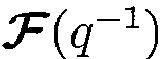 . An identity matrix is a constant matrix with ones on the diagonal. It is denoted I, or I N , if the dimension is N × N . Another constant matrix, e.g., 0 N denotes a zero matrix of dimension N × N. Furthermore, diag([F 1... FN ] T ) denotes a diagonal matrix with F 1 ... FN on the diagonal, whereas trP denotes the trace of the matrix P , which is the sum of the diagonal elements of P .
- The sound generating or reproducing system to be modified will be represented as in
Fig. 2 by a linear time-invariant and stable dynamic modelthat describes the relation in discrete time between a set of N input signals u (t) to a set of M modeled output signals y (t): represents a model of the acoustic dynamic response, in the form of a transfer function matrix. It is a matrix of dimension M × N whose elements are stable linear dynamic operators or transforms, e.g., represented as FIR filters or IIR filters. These filters determine the response y (t) to a N-dimensional time-dependent input vector u (t). If the M × N modelcontains IIR filters as elements, then it can be written on so-called right Matrix Fraction Description (right MFD) form,
- The transfer function matrixrepresents the effect of the whole or a part of the sound generating, or sound reproducing system, including any pre-existing digital compensators, digital-to-analog converters, analog amplifiers, loudspeakers, cables and the room acoustic response. In other words, the transfer function matrixrepresents the dynamic response of relevant parts of a sound generating system. The input signal u (t) to the system, which is a N-dimensional column vector, may represent input signals to N individual amplifier-loudspeaker chains of the sound generating system. The signal y m(t) (with subscript m denoting "measurement") is a M-dimensional column vector representing the true (measured) sound time-series at the M measurement positions and e (t) represents background noise, unmodelled room reflections, effects of an incorrect model structure, nonlinear distortion and other unmodelled contributions. Each M-dimensional column ofthen represents the M transfer functions between one of the N loudspeaker inputs and the M measurement positions.
- The modelmay also include additive or multiplicative model uncertainties, here represented by a rational matrix. If, for example, the model uncertainties
 are parameterized by polynomial matrices with random coefficients, then a suitable model would be
 is the nominal model and
 , which is partly parameterized by random variables, constitutes the uncertainty model. Writing out the matrix fractions for
 and
and , the decomposition (3) ofexpands into
 , and the elements of Δ B are polynomials with stochastic variables as coefficients. For simplicity we will assume these coefficients to have zero mean and unit variance. The filter
 can be viewed as a set of models, describing a range of possible errors in the measured response of the system. For a general introduction to the above probabilistic modeling framework, the reader is referred to [27] and references therein. Modeling of uncertaintiescan be performed in many ways, and the above formulation is merely one example of how it can be accomplished and used in a systematic way.
- A general objective of sound field control is to modify the dynamics of the sound generating system represented by (1) in relation to a reference dynamics. For this purpose, a reference matrix (or in this case, a column vector)of dynamic systems is introduced:
 is a stable transfer function column vector of dimension M × 1 that is assumed to be known. This linear discrete-time dynamic system is to be specified by the designer. It represents the reference dynamics (desired target dynamics) of the vector y (t) in (1). In the compensated system, the signal w(t) will represent one out of totally L input source signals. Its desired effect at the M measurement positions is represented by the elements,... ,
 of
of in (5). The systemmay include a set of adjustable parameters. Alternatively, it may indirectly be affected by such a set via its specification.
 - The audio precompensation controller is assumed to be realized as a multivariable dynamic discrete-time precompensation filter, generally denoted by, which generates an input signal vector u (t) to the audio reproduction system (1) based on linear dynamic processing of the signal w(t):

- This audio precompensation controller includes a set of adjustable parameters. These parameters should allow sufficient flexibility to modify the input-output dynamic properties of the controller, for example, allowing some elements of, or the whole ofto be zero for appropriate parameter settings. The optimization ofshould however be constrained to parameter settings that makean input-output stable dynamic system.
- Our design objective will be to construct a stable transfer function matrixof dimension N × 1 that is designed to generate an input signal vector u (t) to the audio reproduction system (1) such that its compensated model output y (t) approximates the reference vector y ref(t) well, according to a specified criterion. This objective would be attained if

- The corresponding model-based approximation error at the M measurement positions is represented by

- The true, measured, error vector will then, by
Fig. 2 and (1 ), be y ref(t) - y m(t) = ε(t) - e(t). The approximation (7) can never be made exact in practice with a limited number N of loudspeakers, a large number M of measurement positions and complicated wide-band acoustic dynamic models in. The attainable approximation quality depends on the nature of the problem set-up. For a fixed given acoustic environment, the quality of the approximation can in general be improved if the number of loudspeaker channels N is increased. It may also be improved by increasing the number M of measurement points within the intended listening region, since this gives a denser and more accurate sampling of the sound field as a function of space. Enlargement of the listening region or addition of regions for a fixed N would, in general, result in larger approximation errors. - A scheme for calculating an appropriate approximation for the present problem will be outlined below.
- An important aspect to consider when designing a precompensator is the relation between the initial propagation delay of the system to be compensated and the initial propagation delay of the desired target dynamics. The initial propagation delay of a dynamical system is the time it takes for a signal to propagate from the input to the output of the system. In other words, the initial propagation delay is given by the time instant of the first nonzero coefficient of the impulse response of the system. A systemhaving an initial propagation delay of d samples can therefore be written as
 has an impulse response that starts with a nonzero coefficient.
- Consider for example the system in
Fig. 2 , and suppose thathas an initial propagation delay d 1 andhas an initial propagation delay d 0. If d 1 > d 0, then a causal compensator, which uses only present and past values of w(t), cannot be expected to perform well because at time t the reference signal y ref(t) will depend on signal values w(t - d 0 - k) for k ≥ 0, whereas the output y (t) of the compensated system will depend only on w(t - d 1 - k), for k ≥ 0, i.e., the reference signal depends on more recent data than what can be produced at the system output. The compensator aims at steering y (t) towards the reference y ref(t), but due to the time-lag difference betweenandthe action of the control signal u (t) at the output ofwill always arrive at least d 1 - d 0 samples later than necessary. In order for the compensatorto perform well in such a case, it would have to be non-causal, i.e., it would have to be able to predict at least d 1 - d 0 future values of the signal w(t). If the relation between the initial delays is the opposite, i.e., if d 1 < d 0, then the compensator will perform considerably better because by the knowledge ofand w(t), the compensator has the possibility to predict future values of the reference signal. The compensator may therefore start acting on the dynamics ofby d 0 - d 1 samples in advance, in such a way that the output y (t) is more effectively steered towards the reference y ref(t). - It is thus in general possible to improve the performance of a precompensator by ensuring that the initial delay of the target dynamicsis large enough compared to the initial delay of the system. For example, this can be obtained by adding an overall bulk delay q -d0 to the target, so that
 is the original intended target dynamics, and d 0 is larger than or equal to the initial propagation delay of
 .
. - For audio reproduction purposes, however, allowing a large bulk delay q -d
0 in the target can be problematic. On the one hand, it is generally true that a large bulk delay in the target dynamics is helpful for reducing the average reproduction error, e.g., and. It is thus of interest to use a bulk delay that is large enough to allow the compensator to work properly, but not so large that the compensator can produce audible pre-ringing errors. In other words, to minimize the pre-ringing effects one should use d 1 ≤ d 0 in the above example, with d 1 as close to d 0 as possible.
 - However, it is well known that a large target bulk delay (also called modeling delay or smoothing lag) can improve the performance considerably when the system to be compensated contains non-minimum phase distortion. Moreover, for the single-channel case there exists a method for compensation of non-minimum phase distortion and which does not produce pre-ringings [4, 5, 6]. The method in question uses a large target bulk delay q -d
0 in combination with a noncausal all-pass filterthat compensates the non-minimum phase distortion that is common to all spatial positions. If the delay d 0 is large enough, then the resulting noncausal filter
 is designed for the augmented system
 is designed, a bulk delay of d 0 is still used in the target, which means that the initial propagation delays of the augmented systemand the targetare identical. The causal filtercan therefore not add any pre-ringings to the system.
 - The above method for single-channel compensation without pre-ringings can be exploited also in the design of multichannel compensators, as a "pre-conditioning" step, in which the individual channels of the system are corrected with respect to phase distortion before the multichannel compensator is designed. By extending this approach, a single-channel phase compensator
 and the optimal causal N-channel compensator that is to be designed. That is, the system to be compensated becomes
 are diagonal N × N matrices given by
- The extra delays values d 1, ... , dN above can be used to fine-tune the relation between the initial propagation delay of the target systemand the initial propagation delays of the N loudspeaker channels (i.e., the initial propagation delays of the columns of).
- The room-acoustic impulse responses of each of N loudspeakers are estimated from measurements at M positions which are distributed over the spatial region of intended listener positions. It is recommended that the number of measurement positions M is larger than the number of loudspeakers N. The dynamic acoustic responses can then be estimated by sending out test signals from the loudspeakers, one loudspeaker at a time, and recording the resulting acoustic signals at all M measurement positions. Test signals such as white or colored noise or swept sinusoids may be used for this purpose. Models of the linear dynamic responses from one loudspeaker to M outputs can then be estimated in the form of FIR or IIR filters with one input and M outputs. Various system identification techniques such as the least squares method or Fourier-transform based techniques can be used for this purpose. The measurement procedure is repeated for all loudspeakers, finally resulting in a modelthat is represented by a M × N matrix of dynamic models. The multiple input-multiple output (MIMO) model may alternatively be represented by a state-space description.
- An example of a mathematically convenient, although very general, MIMO model for representing a sound reproduction system is by means of a right MFD with diagonal denominator,
 as defined in (11) may include a parametrization that describes model errors and uncertainties, as given for example by (4).
 - For a given sound reproduction system, a precompensation controller is to be designed with the aim of improving the acoustic reproduction of L source signals by at least one physical loudspeaker. To improve the acoustic reproduction here means that the impulse response of a physical loudspeaker, as measured in a number of points, is altered by the compensator in such a way that its deviation from a specified ideal target response is minimized.
- In order to obtain a compensator that is more general than existing single-channel compensators, the present design is performed under as few restrictions as possible regarding filter structures and how the loudspeakers are used. The only restrictions posed on the compensator is linearity, causality and stability. The restriction of single-channel compensators, i.e., the restriction that each of the L source signals can be processed by only one single filter and distributed to only one loudspeaker input, is here relaxed. The compensator associated with each one of the L source signals is thus allowed to consist of more than one filter, yielding at least one, but possibly several, processed versions of the source signal, to be distributed to at least one, but possibly several, loudspeakers.
- We assume here that the L source signals have been produced with some particular intended physical loudspeaker layout in mind. This layout is assumed to consist of at most L loudspeakers, and each of the L source signals is intended to be fed into at most one loudspeaker input. For example, an established audio source format such as two-channel stereo (L = 2) is intended to be played back through a pair of loudspeakers positioned symmetrically in front of the listener, where the first source channel is fed to the left loudspeaker and the second source channel is fed to the right loudspeaker. Another source format is 5.1 surround which consists of totally six audio channels (L = 6) that are intended to be played back in a one-to-one fashion (i.e., without any cross-mixing of channels) through five loudspeakers and a subwoofer. In the case that the source signals are a result of some upmixing algorithm (for example an algorithm that produces a six-channel 5.1 surround material out of a two-channel stereo recording), we shall associate L with the number of channels in the upmixed material (i.e., in the example of stereo-to-5.1 surround upmix, we shall use L = 6 rather than L = 2). In the down-mix case, i.e., when two or more of the L source signals are fed into the same loudspeaker input, we have the situation of an intended loudspeaker layout with less than L loudspeakers.
- As mentioned above, we here want to construct a compensator that is allowed to use the loudspeakers of a system more freely. The aim of the compensator design is, however, to make the reproduction performance of the original intended loudspeaker layout as good as possible. To accomplish this we shall, for each one of the L source input signals, distinguish between which loudspeaker belongs to that particular source signal in the original intended layout (this loudspeaker is henceforth called the primary loudspeaker of the concerned source signal), and which additional loudspeakers (henceforth called support loudspeakers) are used by the compensator for improving the performance of the primary loudspeaker.
- Suppose that we have L source input signals and a system of totally N loudspeakers. Then, for each one of the L source input signals there must be one associated primary loudspeaker. Among the remaining N - 1 loudspeakers, we then choose a set of S support loudspeakers, where 1 ≤ S ≤ N - 1, to be used by the compensator for improving the performance of the primary loudspeaker.
- Recall that if the sound system is represented by a transfer function matrix model, as for example in (1), then each column ofrepresents the acoustic response of one loudspeaker at M measurement positions. Thus, one of the columns ofcontains the responses of the primary loudspeaker, and the rest of the columns contain the responses of the S support loudspeakers. Therefore, in a particular design of a compensator for one of the L source inputs, the acoustic modelcontains 1+S columns, and the resulting compensator has one input and 1+S outputs, where 1+S may be less than N, depending on how many support loudspeakers were chosen for that particular source input. Note also that it is not necessary to use the same set of loudspeakers repeatedly when compensators are designed for the remaining L - 1 source inputs. The number S of support loudspeakers used by the compensator may therefore not be the same for all of the L source inputs.
- The aim of loudspeaker precompensation is not to generate an arbitrary sound field in a room, but to improve the acoustic response of an existing physical loudspeaker. The target sound field to be defined for one particular (out of L) input source signals is therefore highly determined by the characteristics of the primary loudspeaker associated with that input source signal. The following example is an illustration of how a target sound field can be specified for a specific primary loudspeaker.
- Suppose that the sound system in question is measured in M positions, and is represented with a transfer function matrixas in (1). Moreover, suppose that the jth column ofrepresents the impulse responses of the considered primary loudspeaker. Then a target sound field can be specified in form of a M × 1 column vector of transfer functions,as in (5). Typically, the target sound field should be specified as an idealized version of the measured impulse responses of the primary loudspeaker. An example of how such an idealized set of impulse responses can be designed is to use delayed unit pulses as elements in, i.e., to let the ith elementof
 be defined as
 , i.e.,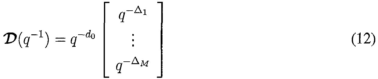
- The target response in (12) is an idealized version of the primary loudspeaker's impulse response, in the sense that it represents a sound wave whose propagation through space (i.e., over the M measurement positions) is similar to that of the primary loudspeaker, but in the time domain the shape of the target sound wave is pulse-like and contains no room echoes. The delays Δ1 . .. , Δ M can be determined by detecting the time lag corresponding to of the first coefficient of non-negligible magnitude in each of the impulse responses in the jth column of. The extra common bulk delay d 0 is optional, but should preferably be included if a diagonal phase compensator with lag d 0 is used, as suggested in (9), (10).
- If there is more than one input source signals, i.e., if L > 1, then one target sound field is defined for each of the L signal sources that are to be reproduced by the sound system.
- If for some reason the propagation delays Δ1 ... , Δ M cannot be properly detected, are ambiguous or in any way difficult to define, then some controlled variability can be introduced into the target. For example, the delays Δ1, ... , Δ M can be adjustable within prescribed limits. Such flexibility of the target can help attain better approximation to the selected target, better criterion values and better perceived audio quality. This type of flexibility can be utilized by adjusting the parameters of the targetand the parameters of the precompensation filter iteratively.
- To obtain analytical techniques for designing audio precompensation filters it is convenient to introduce a scalar criterion that is to be optimized with respect to the adjustable parameters. An example of a suitable criterion consists of a sum or a weighted sum of powers of the difference between the target signal y ref(t) and the compensated signal y (t) in all M measurement points. This difference will, in the sequel, be called the approximation error, or just the error, and the weighted error respectively, which are represented by

- See equations (1), (5) and (8) above. The weighted error z 1(t) is governed by the polynomial matrix V of dimension M × M, which can be a full matrix, a diagonal matrix, or just a constant matrix, depending on in which frequency ranges the error should be emphasized. If V = I i.e., the identity matrix, which is diagonal with ones on the diagonal, then no weighting is applied to the error. Optionally, weighted powers of the N audio precompensator output signals, u (t), see (6), can be added to the criterion. The weighted precompensator output signals will henceforth be called penalty terms, and are represented by

- If, for example, V (q -1) and W (q -1) are diagonal with diagonal elements denoted by Vi (q -1) and Wj (q -1), (i = 1,..., M ; j = 1, ... , N), respectively, then with the weighting terms z 1 (t) and z 2 (t) defined as above, an example of an adequate criterion would be

- Here the statistical expectation E is taken with respect to the signal w(t), whereas the statistical expectation
E is taken with respect to uncertain model parameters in, e.g., Δ B in (4), should such a statistical model description have been selected. The last equality of (15) represents the expected value, with respect to the model uncertainty parameters in, of the squared 2-norm (in (15), the squared 2-norm is denoted as
- As an example, consider (15) with V (q -1) and W (q -1) being diagonal with FIR filters on the diagonal. If all diagonal elements of V (q -1) are low pass filters, then it means that we will prioritize high accuracy (small error) at low frequencies. In a similar manner, if the elements of W (q -1) are high pass filters, then the high frequency contents of the audio precompensation filter output will be penalized (i.e., contribute more to the criterion value) than would the low frequency contents. Hence, an audio precompensation filter that strives to minimize the criterion will put its efforts at low frequencies. By selecting different filters for different error and precompensation signals a designer can balance the different loudspeaker outputs against one another. In the special case with all the FIR filters being ones, no weighting is performed. The weighting polynomial matrices V (q -1) and W (q -1) thus offer considerable flexibility in the design to attain as small an error as possible in the frequency ranges of interest while at the same time use the precompensation signal power wisely.
- It is evident that if V(q -1) is diagonal, then the first right-hand sum of the criterion (15) represents a weighted summation over the M measurement positions of powers of differences between the compensated estimated impulse responses, represented by elements of, and the target impulse responses, represented by elements of
 , where the weighting is performed by the polynomial matrix V (q -1) and by the spectral properties of the signal w(t). Equal weighting of all components of the error vector ε(t) would be obtained if a unit matrix V (q -1) = I is used and if the signal w(t) is a white noise.
 - The criterion (15), which constitutes a squared 2-norm, or other forms of criteria, based e.g., on other norms, can be optimized in several ways with respect to the adjustable parameters of the precompensator. It is also possible to impose structural constraints on the precompensator, such as e.g., requiring its elements to be FIR filters of certain fixed orders, and then perform optimization of the adjustable parameters under these constraints. Such optimization can be performed with adaptive techniques, or by the use of FIR Wiener filter design methods. However, as all structural constraints lead to a constrained solution space, the attainable performance will be inferior compared with problem formulations without such constraints. Hence, the optimization should preferably be performed without structural constraints on the precompensator, except for causality of the precompensator and stability of the compensated system. With the optimization problem stated as above, the problem becomes a Linear Quadratic Gaussian (LQG) design problem for the multivariable feedforward compensator.
- Linear quadratic theory provides optimal linear controllers, or precompensators, for linear systems and quadratic criteria, see e.g., [1, 19, 20, 31]. If the involved signals are assumed to be Gaussian, then the LQG precompensator, obtained by optimizing the criterion (15) can be shown to be optimal not only among all linear controllers but also among all nonlinear controllers, see e.g., [1]. Hence, optimizing the criterion (15) with respect to the adjustable parameters of, under the constraint of causality ofand stability of the compensated system, is very general. Withandassumed stable, stability of the compensated system, or error transfer operator,
 .
. - We will now present the LQG-optimal precompensator for the problem defined by equations (1) - (14) and the criterion (15). The solution is given in transfer operator, or transfer function form, using polynomial matrices. Techniques for deriving such solutions has been presented in e.g., [31]. Alternatively, the solution can be derived by means of state space techniques and the solution of Riccati equations, see e.g., [1, 20].
- Let the system be described by the model (1) withparameterized as in (3), and (4). If no uncertainty modeling is used then we set Δ B = 0 and we obtain
 = D /E, i.e.,
- If maximum attainable compensator performance is desired, under the constraint that preringing artifacts are to be avoided, then an individual phase compensation and time-delay alignment of the involved loudspeakers will preferably be performed prior to the precompensator optimizations. Such phase compensations can be designed according to the principles described in [5], [6]. In order to obtain maximum performance while constraining the solution to not include any preringing artifacts, an all-pass phase compensation filter
 and the controller, and the target should then contain an initial delay of d 0 samples, i.e.,

- Introduce the delay polynomial matrix Δ̃(q -1), and the all-pass rational matrix, respectively, as follows

- Here diag(·) denotes a diagonal matrix with the elements of the vector on the diagonal, (·) T means the transpose of the same vector, whereas
F j (q -1) is the reciprocal polynomial of Fj (q -1), i.e., the zeros ofF j (z -1) are in the mirror locations, with respect to the unit circle, to those of Fj (z -1). The rational matrixis here constructed from excess phase zeros that are common among the transfer functions of each of the N loudspeakers for all M measurement positions. That is, the elements B 1j ,..., BMj of the jth column of B in (4) are assumed to share a common excess phase factorF j (q -1). - As explained above, d 0 in (18) is the intended initial delay of the phase-compensated system, whereas dj , j = 1, ... , N are individual delays that can be used to accomodate individual deviations in distances among the different loudspeakers. Since Δ̃(q -1) and, or equivalently, its complex conjugate transpose, here denoted, are fixed and known they can be regarded as factors of an augmented systemrepresented as,

 . The second equality of (19) is allowed because A , Δ̃ and
 are diagonal, see (4), (11) and (18).
 - Given the systemabove, with the fixed and known delay polynomial matrix Δ̃(q -1), the all-pass rational matrix, and assuming the signal w(t) being a zero mean unit variance white noise sequence, then the optimal LQG-precompensator, free of preringing artifacts, which minimizes the criterion (15) under the constraint of causality and stability, is obtained as,
 is the unique stable right spectral factor1 defined by

Diophantine equation 

- The optimality and uniqueness of the compensator derived above can be proven by using the techniques presented in [27, 31]. The solution presented above, can easily be extended to also account for w(t) being described by a dynamic model i.e.,
 = P(q -1)S(q -1)-1 with P and S being stable polynomials, then, in the rightmost term of (22) P - 1SE is substituded for E. Describing w(t) by a dynamic model can sometimes be useful in certain applications when the assumtion of w(t) being a white noise is inappropriate. The solution obtained here is thus very general, which gives considerable flexibility in the design of the precompensator.
- The filter design presented above can also be used to design a set of p filters


1Such a right spectral factor exists under mild conditions for the current problem. See section 3.3. of [31]. The spectral factor is unique up to an orthogonal matrix.
2Lower degrees may occur in special cases.
- In order to obtain the precompensator signal
 . One could also, for example, use high-order FIR approximations of the elements in. Such an FIR approximation can be obtained by using a unit pulse, δ(t), as input signal and record a series of samples at the N outputs of the filter. The recorded N output signals then constitute the impulse responses of the elements of, and the FIR filter coefficients are obtained by truncating the output signals at an appropriate length.
 - It should be noted that if no individual phase compensation is performed on each one of the N loudspeakers, then B̌ 0∗ = B̂ 0∗ and B̃ (q -1) = B̂ 0(q -1) + Δ B (q -1) B̂ 1(q -1). If, on the other hand, no model uncertainty is used in the design, then the third right hand term of (21) will vanish and

- In a practical controller design, the third term on the right hand side of (21) is readily obtained by evaluating, see [26, 27, 32],

- Now recall that the random coefficients of the individual polynomial elements of Δ B are specified as a zero mean, unit variance white noise sequences, implying that
E {Δ B (i,j)Δ B (i,j)∗} = 1. Furthermore, it is assumed that these random coefficients are uncorrelated between different columns of Δ B , i.e.,E {Δ B (i,j)Δ B (m,n)∗} = 0 for j ≠ n, since reverberation fields belonging to separate sources are, in general, spatially uncorrelated. We therefore know, firstly, that the M|M-dimensional polynomial matrixE {Δ B (:,i)Δ B (:,i)∗} contains ones along its diagonal and, secondly, thatE {Δ B (:,j)Δ B (:,i)∗} = 0 M if i ≠ j. Moreover, if the polynomial matrix V ∗ V is diagonal, then we obtain
E {Δ B ∗ V ∗ VΔB } in (21) becomes
- An important insight here is that, due to the diagonal structure of the error weight V ∗ V and the trace operator appearing in (25), the off-diagonal elements of
E {Δ B (:,j)Δ B (:,i)∗} will not contribute to the filter design. Since these off-diagonal elements constitute the "spatial covariances"E {Δ B (i,j)Δ B (m,n)∗} with i ≠ m, we conclude that spatial covariances in the uncertainty model, will be superfluous for the type of filter design studied here. The off-diagonal elements ofE {Δ B ∗ V ∗ VΔ B } can however be used in the design by selecting the off-diagonal elements of V ∗ V different from zero. For example, these off-diagonal elements can be used to downgrade the importance of peripherial measurement points in the design compared with the central ones. - When a sound system is reproducing music, it is mostly preferable that the magnitude spectrum of the system's transfer functions is smooth and well balanced, at least on average over the listening region. If the compensated system perfectly attains the desired targetat all positions, then the average magnitude response of the compensated system will be equal to that of the target. However, since the designed controllercannot be expected to fully reach the target responseat all frequencies, e.g., due to very complex room reverberation that cannot be fully compensated for, there will always be some remaining approximation errors in the compensated system. These approximation errors may have different magnitude at different frequencies, and they may affect the quality of the reproduced sound. Magnitude response imperfections are generally undesirable and the controller matrix should preferably be adjusted so that an overall target magnitude response is reached on average in all the listening regions.
- A final design step is therefore preferably added after the criterion minimization with the aim of adjusting the controller response so that, on average, a target magnitude response is well approximated on average over the measurement positions. To this end, the magnitude responses of the overall system (i.e., the system including the controller) can be evaluated in the various listening positions, based on the design models or based on new measurements. A minimum phase filter can then be designed so that on average (in the RMS sense) the target magnitude response is reached in all listening regions. As an example, variable fractional octave smoothing based on the spatial response variations may be employed in order not to overcompensate in any particular frequency region. The result is one scalar equalizer filter that adjusts all the elements ofby an equal amount.
- An example of the performance of the suggested precompensator design, and its difference from a traditional single-channel design is shown in
Fig. 6-11 : -
Fig. 6 andFig. 9 show the frequency responses and average cumulative spectral decay ("waterfall plot"), respectively, of an ATC SCM16 studio monitor loudspeaker, measured at 64 positions in a room. -
Fig. 7 andFig. 10 show the frequency responses and average waterfall plot respectively, of the same loudspeaker after a single-channel precompensator has been applied to the input of the loudspeaker. -
Fig. 8 andFig. 11 show the frequency responses and average waterfall plot when the new multichannel design method has been applied. The objective of the compensator design was here the same as for the single-channel design ofFig. 7 andFig. 10 , i.e., the single loudspeaker of the previous figures was used as primary loudspeaker and the aim was to make the response of this primary loudspeaker as ideal as possible. In order to better reach the target, an additional 15 loudspeakers were used as support loudspeakers. The support loudspeakers were surrounding the listening region where the measurements were taken, and they were positioned at various heights and at various distances from the listening region. - The resulting filterof (20) can be realized in any number of ways, in state space form or in transfer function form. The required filters are in general of very high order, in particular if a full audio range sampling rate is used and if also room acoustic dynamics have been taken into account in the model on which the design is based. To obtain a computationally feasible design, methods for limiting the computational complexity of the precompensator are of interest. We here outline one method for this purpose that is based on controller order reduction of elements of the controller matrix, in particular of any transfer functions that have impulse responses with very long but smooth tails. The method works as follows.
- The relevant scalar impulse response elements,...,of the pre-compensator
 are first represented as very long FIR filters, as mentioned above. Then, for each precompensator impulse response, do the following:
- 1. Determine a lag t 1 > 1 after which the impulse response is approximately exponentially decaying and has a smooth shape, and a second lag t 2 > t 1 after which the impulse response coefficients are negligible.
- 2. Use a model reduction or system identification technique to adjust a low-order recursive IIR filter to approximate the FIR filter tail for a delay interval [t 1, t 2]
- 3. Realize the approximated scalar precompensator filter as a parallel connection

1 N(q -1), where M(q -1) is a FIR filter that equals the first t 1 impulse response coefficients of the original FIR filter, from lag zero to lag t 1 -1, while N(q -1) is the IIR filter that approximates it tail.
- The aim of this procedure is to obtain realizations in which the sum of the number of parameters in the FIR filter M(q -1) and the IIR filter N(q -1) is much lower than the original number of impulse response coefficients. Various different methods for approximating the tail of the impulse response can be used, for example adjustment of autoregressive models to a covariance sequence based on the Yule-Walker equations. To obtain low numerical sensitivity to rounding errors of coefficients when implementing the resulting IIR filters with finite precision arithmetic, it is preferable to implement them as parallel connections or series connections of lower order filters. As an example, first order filters or second order IIR filter elements (so-called biquadratic filters) may be used.
- Typically, the design methodology is executed on a computer system to produce the filter parameters of the precompensation filter. The calculated filter parameters are then normally downloaded to a digital filter, for example realized by a digital signal processing system or similar computer system, which executes the actual filtering.
- Although the invention can be implemented in software, hardware, firmware or any combination thereof, the filter design scheme proposed by the invention is preferably implemented as software in the form of program modules, functions or equivalent. The software may be written in any type of computer language, such as C, C++ or even specialized languages for digital signal processors (DSPs). In practice, the relevant steps, functions and actions of the invention are mapped into a computer program, which when being executed by the computer system effectuates the calculations associated with the design of the precompensation filter. In the case of a PC-based system, the computer program used for the design or determination of the audio precompensation filter is normally encoded on a computer-readable medium such as a DVD, CD or similar structure for distribution to the user/filter designer, who then may load the program into his/her computer system for subsequent execution. The software may even be downloaded from a remote server via the Internet.
- There is thus provided a system, and corresponding computer program product, for determining an audio precompensation controller for an associated sound generating system comprising a total of N ≥ 2 loudspeakers, each having a loudspeaker input, where the audio precompensation controller has a number L ≥ 1 inputs for L input signal(s) and N outputs for N controller output signals, one to each loudspeaker of the sound generating system. Keeping in mind that the audio precompensation controller has a number of adjustable filter parameters to be determined. The system basically comprises means for estimating, for each one of at least a subset of the N loudspeaker inputs, an impulse response at each of a plurality M ≥ 2 of measurement positions, distributed in a region of interest in a listening environment, based on sound measurements at the M measurement positions. The system also comprises means for specifying, for each one of the L input signal(s), a selected one of the N loudspeakers as a primary loudspeaker and a selected subset S including at least one of the N loudspeakers as support loudspeaker(s), where the primary loudspeaker is not part of the subset. The system further comprises means for specifying, for each primary loudspeaker, a target impulse response at each of the M measurement positions with the target impulse response having an acoustic propagation delay, where the acoustic propagation delay is determined based on the distance from the primary loudspeaker to the respective measurement position. The system also comprises means for determining, for each one of the L input signal(s), based on the selected primary loudspeaker and the selected support loudspeaker(s), filter parameters of the audio precompensation controller so that a criterion function is optimized under the constraint of stability of the dynamics of the audio precompensation controller. The criterion function is defined to include a weighted summation of powers of differences between the compensated estimated impulse responses and the target impulse responses over the M measurement positions.
- For the case where L ≥ 2, the system may also include means for merging all of the filter parameters, determined for the L controller input signals, into a merged set of filter parameters for the audio precompensation controller. The audio precompensation controller, with the merged set of filter parameters, is then configured for operating on the L input signals to generate the N controller output signals to the loudspeakers to attain the desired target impulse responses.
- In a particular example, the means for determining filter parameters of the audio precompensation controller is configured to operate based on a Linear Quadratic Gaussian (LQG) optimization of the parameters of a stable, linear and causal multivariable feedforward controller based on a given target dynamical system, and a dynamical model of the sound generating system..
- The computer program product comprises corresponding program means, and is configured for determining the audio precompensation controller when running on a computer system.
-
Fig. 4 is a schematic block diagram illustrating an example of a computer system suitable for implementation of a filter design algorithm according to the invention. Thefilter design system 100 may be realized in the form of any conventional computer system, including personal computers (PCs), mainframe computers, multiprocessor systems, network PCs, digital signal processors (DSPs), and the like. Anyway, thesystem 100 basically comprises a central processing unit (CPU) or digital signal processor (DSP)core 10, asystem memory 20 and asystem bus 30 that interconnects the various system components. Thesystem memory 20 typically includes a read only memory (ROM) 22 and a random access memory (RAM) 24. Furthermore, thesystem 100 normally comprises one or more driver-controlledperipheral memory devices 40, such as hard disks, magnetic disks, optical disks, floppy disks, digital video disks or memory cards, providing non-volatile storage of data and program information. Eachperipheral memory device 40 is normally associated with a memory drive for controlling the memory device as well as a drive interface (not illustrated) for connecting thememory device 40 to thesystem bus 30. A filter design program implementing a design algorithm according to the invention, possibly together with other relevant program modules, may be stored in theperipheral memory 40 and loaded into theRAM 24 of thesystem memory 20 for execution by theCPU 10. Given the relevant input data, such as measurements, input specifications, and possibly a model representation and other optional configurations, the filter design program calculates the filter parameters of the audio precompensation controller/filter. - The determined filter parameters are then normally transferred from the
RAM 24 in thesystem memory 20 via an I/O interface 70 of thesystem 100 to anaudio precompensation controller 200. Preferably, theaudio precompensation controller 200 is based on a digital signal processor (DSP) or similar central processing unit (CPU) 202, and one ormore memory modules 204 for holding the filter parameters and the required delayed signal samples. Thememory 204 normally also includes a filtering program, which when executed by theprocessor 202, performs the actual filtering based on the filter parameters. - Instead of transferring the calculated filter parameters directly to the
audio precompensation controller 200 via the I/O system 70, the filter parameters may be stored on a peripheral memory card ormemory disk 40 for later distribution to an audio precompensation controller, which may or may not be remotely located from thefilter design system 100. The calculated filter parameters may also be downloaded from a remote location, e.g. via the Internet, and then preferably in encrypted form. - In order to enable measurements of sound produced by the audio equipment under consideration, any conventional microphone unit(s) or similar recording equipment may be connected to the
computer system 100, typically via an analog-to-digital (A/D) converter. Based on measurements of (conventional) audio test signals made by the microphone unit, thesystem 100 can develop a model of the audio system, using an application program loaded into thesystem memory 20. The measurements may also be used to evaluate the performance of the combined system of precompensation filter and audio equipment. If the designer is not satisfied with the resulting design, he may initiate a new optimization of the precompensation filter based on a modified set of design parameters. - Furthermore, the
system 100 typically has auser interface 50 for allowing user-interaction with the filter designer. Several different user-interaction scenarios are possible. - For example, the filter designer may decide that he/she wants to use a specific, customized set of design parameters in the calculation of the filter parameters of the
audio precompensation controller 200. The filter designer then defines the relevant design parameters via theuser interface 50. - It is also possible for the filter designer to select between a set of different pre-configured parameters, which may have been designed for different audio systems, listening environments and/or for the purpose of introducing special characteristics into the resulting sound. In such a case, the preconfigured options are normally stored in the
peripheral memory 40 and loaded into the system memory during execution of the filter design program. - The filter designer may also define a reference system by using the
user interface 50. Instead of determining a system model based on microphone measurements, it is also possible for the filter designer to select a model of the audio system from a set of different preconfigured system models. Preferably, such a selection is based on the particular audio equipment with which the resulting precompensation filter is to be used. Another option is to design a set of filters for a selected appropriate set of weighting matrices to be able to vary the degree of support provided by the selected set of support loudspeakers. - Preferably, the audio filter is embodied together with the sound generating system so as to enable reproduction of sound influenced by the filter.
- In an alternative implementation, the filter design is performed more or less autonomously with no or only marginal user participation. An example of such a construction will now be described. The exemplary system comprises a supervisory program, system identification software and filter design software. Preferably, the supervisory program first generates test signals and measures the resulting acoustic response of the audio system. Based on the test signals and the obtained measurements, the system identification software determines a model of the audio system. The supervisory program then gathers and/or generates the required design parameters and forwards these design parameters to the filter design program, which calculates the audio precompensation filter parameters. The supervisory program may then, as an option, evaluate the performance of the resulting design on the measured signal and, if necessary, order the filter design program to determine a new set of filter parameters based on a modified set of design parameters. This procedure may be repeated until a satisfactory result is obtained. Then, the final set of filter parameters are downloaded/implemented into the audio precompensation controller.
- It is also possible to adjust the filter parameters of the precompensation filter adaptively, instead of using a fixed set of filter parameters. During the use of the filter in an audio system, the audio conditions may change. For example, the position of the loudspeakers and/or objects such as furniture in the listening environment may change, which in turn may affect the room acoustics, and/or some equipment in the audio system may be exchanged by some other equipment leading to different characteristics of the overall audio system. In such a case, continuous or intermittent measurements of the sound from the audio system in one or several positions in the listening environment may be performed by one or more microphone units, possibly wirelessly connected, or similar sound recording equipment. The recorded sound data may then be fed, possibly wirelessly, into a filter design system, which calculates a new audio system model and adjusts the filter parameters so that they are better adapted for the new audio conditions.
- Naturally, the invention is not limited to the arrangement of
Fig. 4 . As an alternative, the design of the precompensation filter and the actual implementation of the filter may both be performed in one and thesame computer system - The audio precompensation controller may be realized as a standalone equipment in a digital signal processor or computer that has an analog or digital interface to the subsequent amplifiers, as mentioned above. Alternatively, it may be integrated into the construction of a digital preamplifier, a car audio system, a cinema theatre audio system, a concert hall audio system, a computer sound card, a compact stereo system, a home audio system, a computer game console, a TV, a docking station for an MP3 player, a soundbar or any other device or system aimed at producing sound. It is also possible to realize the precompensation filter in a more hardware-oriented manner, with customized computational hardware structures, such as FPGAs or ASICs.
- In a particular example, the audio precompensation controller is implemented as a linear stable causal feedforward controller.
- It should be understood that the precompensation may be performed separate from the distribution of the sound signal to the actual place of reproduction. The precompensation signal generated by the precompensation filter does not necessarily have to be distributed immediately to and in direct connection with the sound generating system, but may be recorded on a separate medium for later distribution to the sound generating system. The compensation signal could then represent for example recorded music on a CD or DVD disk that has been adjusted to a particular audio equipment and listening environment. It can also be a precompensated audio file stored on an Internet server for allowing subsequent downloading of the file to a remote location over the Internet.
- The embodiments described above are to be understood as a few illustrative examples of the present invention. It will be understood by those skilled in the art that various modifications, combinations and changes may be made to the embodiments without departing from the scope of the present invention. In particular, different part solutions in the different embodiments can be combined in other configurations, where technically possible. The scope of the present invention is, however, defined by the appended claims.
-
- [1] B. D. O. Anderson and J. B. Moore. Optimal Control, Linear Quadratic Methods. Prentice-Hall, Englewood Cliffs, NJ, 1990.
- [2] J. Bauck and D. H. Cooper. Generalized transaural stereo and applications. Journal of the Audio Engineering Society, 44(9):683-705, September 1996.
- [3] S. Bharitkar and C. Kyriakakis. Phase equalization for multi-channel loudspeaker-room responses. US Patent
US 7 720 237 . - [4] L.-J. Brännmark. Robust audio precompensation with probabilistic modeling of transfer function variability. In IEEE Workshop on Applications of Signal Processing to Audio and Acoustics, WASPAA'09, Proceedings, pages 193-196, New Paltz, NY, October 2009.
- [5] L.-J. Brännmark and A. Ahlén. Spatially robust audio compensation based on SIMO feedforward control. IEEE Transactions on Signal Processing, 57(5), May 2009.
- [6] L.-J. Brännmark, M. Sternad, and A. Ahlén. Spatially robust audio precompensation. European Patent
EP 2 104 374 . - [7] A. Celestinos and S. Birkedal Nielsen. Time based room correction system for low frequencies using multiple loudspeakers. Presented at the AES 32nd International Conference: DSP for Loudspeakers, September 2007.
- [8] A. Celestinos and S. Birkedal Nielsen. Controlled acoustic bass system (CABS) A method to achieve uniform sound field distribution at low frequencies in rectangular rooms. J. Audio Eng. Soc, 56(11):915-931, 2008.
- [9] E. Corteel. Equalization in an extended area using multichannel equalization and wave field synthesis. Journal of the Audio Engineering Society, 54(12):1140-1161, December 2006.
- [10] J. Daniel, R. Nicol, and S. Moreau. Further investigations of high order ambisonics and wavefield synthesis for holophonic sound imaging. Presented at AES 114th Convention, Amsterdam. Preprint 5788. Audio Engineering Society, March 2003.
- [11] S. J. Elliott, I. M. Stothers, and P. A. Nelson. A multiple error LMS algorithm and its application to the active control of sound and vibration. IEEE Transactions on Acoustics, Speech and Signal Processing, 35(10):1423-1434, October 1987.
- [12] F. M. Fazi, P. A. Nelson, J. E. N. Christensen, and J. Seo. Surround system based on three dimensional sound field reconstruction. Presented at AES 125th Convention, San Francisco. Preprint 7555. Audio Engineering Society, October 2008.
- [13] L. D. Fielder. Analysis of traditional and reverberation-reducing methods of room equalization. Journal of the Audio Engineering Society, 51(1/2):3-26, January/February 2004.
- [14] P. Hatziantoniou and J. Mourjopoulos. Errors in real-time room acoustics dereverberation. Journal of the Audio Engineering Society, 52(9):883-899, September 2004.
- [15] T. Kailath. Linear Systems. Prentice-Hall, Englewood Cliffs, NJ, 1980.
- [16] M. Karjalainen, A. Mäkivirta, P. Antsalo, and V. Välimäki. Method for designing a modal equalizer for a low frequency sound reproduction. US Patent
US 7 742 607 . - [17] M. Karjalainen, T. Paatero, J. Mourjopoulos, and P. Hatziantoniou. About room response equalization and dereverberation. In IEEE Workshop on Applications of Signal Processing to Audio and Acoustics, WASPAA'05, Proceedings, pages 183-186, New Paltz, NY, October 2005.
- [18] M. Kolundžija, C. Faller, and M. Vetterli. Reproducing sound fields using MIMO acoustic channel inversion. Journal of the Audio Engineering Society, 59(10):721-734, October 2011.
- [19] V. Kučera. Analysis and Design of Discrete Linear Control Systems. Academia, Prague, 1991.
- [20] H. Kwakernaak and R. Sivan. Linear Optimal Control Systems. Wiley, New York, 1972.
- [21] A. Mäkivirta, P. Antsalo, M. Karjalainen, and V. Välimäki. Modal equalization of loudspeaker-room responses at low frequencies. J. Audio Eng. Soc, 51(5):324-343, 2003.
- [22] M. Miyoshi and Y. Kaneda. Inverse filtering of room acoustics. IEEE Transactions on Acoustics, Speech and Signal Processing, 36(2):145-152, February 1988.
- [23] S. T. Neely and J. B. Allen. Invertibility of a room impulse response. The Journal of the Acoustical Society of America, 66(1):165-169, July 1979.
- [24] P. A. Nelson, O. Kirkeby, and T. Takeuchi. Sound fields for the production of virtual acoustic images. Journal of Sound and Vibration, 204(2):386-396, July 1997.
- [25] P. A. Nelson, F. Orduña-Bustamante, D. Engler, and H. Hamada. Experiments on a system for the synthesis of virtual acoustic sources. Journal of the Audio Engineering Society, 44(11):990-1007, November 1996.
- [26] K. Öhrn. Design of Multivariable Cautious Discrete-Time Wiener Filters: A Probabilistic Approach. PhD thesis, Uppsala University, Sweden, 1996.
- [27] K. Öhrn, A. Ahlén, and M. Sternad. A probabilistic approach to multivariable robust filtering and open-loop control. IEEE Transactions on Automatic Control, 40(3):405-418, March 1995.
- [28] M. A. Poletti. Three-dimensional surround sound systems based on spherical harmonics. Journal of the Audio Engineering Society, 53(11):1004-1025, November 2005.
- [29] S. Spors, H. Buchner, R. Rabenstein, and W. Herbordt. Active listening room compensation for massive multichannel sound reproduction systems using wave-domain adaptive filtering. The Journal of the Acoustical Society of America, 122(1):354-369, July 2007.
- [30] S. Spors, R. Rabenstein, and J. Ahrens. The theory of wave field synthesis revisited. Presented at AES 124th Convention, Amsterdam. Preprint 7358. Audio Engineering Society, May 2008.
- [31] M. Sternad and A. Ahlén. LQ controller design and self-tuning control. In K. Hunt, editor, Polynomial Methods in Optimal Control and Filtering, pages 56-92. Peter Peregrinus, London, UK, 1993.
- [32] M. Sternad and A. Ahlén. Robust filtering and feedforward control based on probabilistic descriptions of model errors. Automatica, 29(3):661-679, 1993.
- [33] J. Vanderkooy. Multi-source room equalization: Reducing room resonances. Presented at AES 123rd Convention, New York. Preprint 7262. Audio Engineering Society, October 2007.
- [34] T. Welti and A. Devantier. Low-frequency optimization using multiple subwoofers. J. Audio Eng. Soc, 54(5):347-364, 2006.
Claims (22)
- A method for determining an audio precompensation controller for an associated sound generating system comprising a total of N ≥ 2 loudspeakers, each having a loudspeaker input, said audio precompensation controller having a number L ≥ 1 inputs for L input signal or signals and N outputs for N controller output signals, one to each loudspeaker of said sound generating system, said audio precompensation controller having a number of adjustable filter parameters, with said method comprising the steps of:• estimating (S1), for each one of at least a subset of said N loudspeaker inputs, an impulse response at each of a plurality M ≥ 2 of measurement positions, distributed in a region of interest in a listening environment, based on sound measurements at said M measurement positions;• specifying (S2), for each one of said L input signal or signals, a selected one of said N loudspeakers as a primary loudspeaker and a selected subset S including at least one of said N loudspeakers as support loudspeaker or loudspeakers, where said primary loudspeaker is not part of said subset;• specifying (S3), for each primary loudspeaker, a target impulse response at each of said M measurement positions with said target impulse response having an acoustic propagation delay, where said acoustic propagation delay is determined based on the distance from the primary loudspeaker to the respective measurement position;• determining (S4), for each one of said L input signal or signals, based on the selected primary loudspeaker and the selected support loudspeaker or loudspeakers, filter parameters of said audio precompensation controller so that a criterion function is optimized under the constraint of stability of the dynamics of said audio precompensation controller, with said criterion function including a weighted summation of powers of differences between compensated estimated impulse responses defined by the estimated impulse responses compensated by the audio precompensation controller and the target impulse responses over said M measurement positions.
- The method of claim 1, wherein L ≥ 2, and said method comprises the step of merging (S5) all of said filter parameters, determined for said L input signals, into a merged set of filter parameters for said audio precompensation controller, wherein said audio precompensation controller with said merged set of filter parameters is configured for operating on said L input signals to generate said N controller output signals to said loudspeakers to attain said target impulse responses.
- The method of claim 1 or 2, wherein said audio precompensation controller is configured for controlling the acoustic response of P primary loudspeakers, where P ≤ L and P ≤ N, by the combined use of said P primary loudspeakers and, for each primary loudspeaker, an additional number of support loudspeakers 1 ≤ S ≤ N - 1 of said N loudspeakers.
- The method of any of the preceding claims, wherein said audio precompensation controller has the ability of producing output zero to some of said N loudspeakers for some setting of its adjustable filter parameters.
- The method of any of the preceding claims, wherein said step (S4) of determining filter parameters of said audio precompensation controller is based on a Linear Quadratic Gaussian, LQG, optimization of the parameters of a stable, linear and causal multivariable feedforward controller based on a given target dynamical system, and a dynamical model of the sound generating system.
- The method of any of the preceding claims, wherein each one of said N controller output signals of said audio precompensation controller is fed to a respective loudspeaker via an all-pass filter including a phase compensation component and a delay component, yielding N filtered controller output signals.
- The method of any of the preceding claims, wherein said criterion function includes penalty terms, with said penalty terms being such that said audio precompensation controller, obtained by optimizing said criterion function, produces signal levels of constrained magnitude on a selected subset of said precompensation controller outputs, yielding constrained signal levels on selected loudspeaker inputs to said N loudspeakers for specified frequency bands.
- The method of claim 7, wherein said penalty terms are differently chosen a number of times and said step of determining filter parameters of said audio precompensation controller is repeated for each choice of said penalty terms, resulting in a number of instances of said audio precompensation controller, each of which produces signal levels with individually constrained magnitudes to said S support loudspeakers for specified frequency bands.
- The method of any of the preceding claims, wherein said criterion function includes, firstly, a set of models describing a range of possible errors in the estimated impulse responses, and secondly, an aggregation operation, where said aggregation operation is a sum, a weighted sum or a statistical expectation over said set of models.
- The method of any of the preceding claims, wherein said step (S4) of determining filter parameters of said audio precompensation controller is also based on adjusting filter parameters of said audio precompensation controller to reach a target magnitude frequency response of said sound generating system including said audio precompensation controller, in at least a subset of said M measurement positions.
- The method of any of the preceding claims, where the target impulse responses are nonzero and include adjustable parameters that can be modified within prescribed limits.
- The method of any of the preceding claims, wherein said step (S1) of estimating, for each one of at least a subset of said N loudspeaker inputs, an impulse response at each of a plurality M of measurement positions is based on a model describing the dynamical response of said sound generating system at said M measurement positions.
- The method of claim 1, wherein said audio precompensation controller is created by implementing said filter parameters in an audio filter structure.
- The method of claim 13, wherein said audio filter structure is embodied together with said sound generating system to enable generation of said target impulse response at said M measurement positions in said listening environment.
- A system (100) for determining an audio precompensation controller (200) for an associated sound generating system comprising a total of N ≥ 2 loudspeakers, each having a loudspeaker input, said audio precompensation controller (200) having a number L ≥ 1 inputs for L input signal or signals and N outputs for N controller output signals, one to each loudspeaker of said sound generating system, said audio precompensation controller having a number of adjustable filter parameters, with said system (100) comprising:• means for estimating, for each one of at least a subset of said N loudspeaker inputs, an impulse response at each of a plurality M ≥ 2 of measurement positions, distributed in a region of interest in a listening environment, based on sound measurements at said M measurement positions;• means for specifying, for each one of said L input signal or signals, a selected one of said N loudspeakers as a primary loudspeaker and a selected subset S including at least one of said N loudspeakers as support loudspeaker or loudspeakers, where said primary loudspeaker is not part of said subset;• means for specifying, for each primary loudspeaker, a target impulse response at each of said M measurement positions with said target impulse response having an acoustic propagation delay, where said acoustic propagation delay is determined based on the distance from the primary loudspeaker to the respective measurement position;• means for determining, for each one of said L input signal or signals, based on the selected primary loudspeaker and the selected support loudspeaker or loudspeakers, filter parameters of said audio precompensation controller so that a criterion function is optimized under the constraint of stability of the dynamics of said audio precompensation controller, with said criterion function including a weighted summation of powers of differences between compensated estimated impulse responses defined by the estimated impulse responses compensated by the audio precompensation controller and the target impulse responses over said M measurement positions.
- The system of claim 15, wherein L ≥ 2, and said system (100) comprises means for merging all of said filter parameters, determined for said L controller input signals, into a merged set of filter parameters for said audio precompensation controller, wherein said audio precompensation controller with said merged set of filter parameters is configured for operating on said L input signals to generate said N controller output signals to said loudspeakers to attain said target impulse responses.
- The system of claim 15 or 16, wherein said means for determining filter parameters of said audio precompensation controller is configured to operate based on a Linear Quadratic Gaussian, LQG, optimization of the parameters of a stable, linear and causal multivariable feedforward controller based on a given target dynamical system, and a dynamical model of the sound generating system.
- A computer program product (40;24) for determining, when running on a computer system (100), an audio precompensation controller for an associated sound generating system comprising a total of N ≥ 2 loudspeakers, each having a loudspeaker input, said audio precompensation controller having a number L ≥ 1 inputs for L input signal or signals and N outputs for N controller output signals, one to each loudspeaker of said sound generating system, said audio precompensation controller having a number of adjustable filter parameters, with said computer program product (40;24) comprising:• program means for estimating, for each one of at least a subset of said N loudspeaker inputs, an impulse response at each of a plurality M ≥ 2 of measurement positions, distributed in a region of interest in a listening environment, based on sound measurements at said M measurement positions;• program means for specifying, for each one of said L input signal or signals, a selected one of said N loudspeakers as a primary loudspeaker and a selected subset S including at least one of said N loudspeakers as support loudspeaker or loudspeakers, where said primary loudspeaker is not part of said subset;• program means for specifying, for each primary loudspeaker, a target impulse response at each of said M measurement positions with said target impulse response having an acoustic propagation delay, where said acoustic propagation delay is determined based on the distance from the primary loudspeaker to the respective measurement position;• program means for determining, for each one of said L input signal or signals, based on the selected primary loudspeaker and the selected support loudspeaker or loudspeakers, filter parameters of said audio precompensation controller so that a criterion function is optimized under the constraint of stability of the dynamics of said audio precompensation controller, with said criterion function including a weighted summation of powers of differences between compensated estimated impulse responses defined by the estimated impulse responses compensated by the audio precompensation controller and the target impulse responses over said M measurement positions.
- The computer program product of claim 18, wherein L ≥ 2, and said computer program product comprises program means for merging all of said filter parameters, determined for said L input signals, into a merged set of filter parameters for said audio precompensation controller, wherein said audio precompensation controller with said merged set of filter parameters is configured for operating on said L input signals to generate said N controller output signals to said loudspeakers to attain said target impulse responses.
- The computer program product of claim 18 or 19, wherein said means for determining filter parameters of said audio precompensation controller is configured to operate based on a Linear Quadratic Gaussian, LQG, optimization of the parameters of a stable, linear and causal multivariable feedforward controller based on a given target dynamical system, and a dynamical model of the sound generating system.
- An audio precompensation controller (200) determined by using the method of any of the claims 1 to 14.
- An audio system comprising a sound generating system and an audio precompensation controller (200) in the input path to said sound generating system, wherein said audio precompensation controller is determined by using the method of any of the claims 1 to 14.
Applications Claiming Priority (1)
| Application Number | Priority Date | Filing Date | Title |
|---|---|---|---|
| PCT/SE2012/050320 WO2013141768A1 (en) | 2012-03-22 | 2012-03-22 | Audio precompensation controller design using a variable set of support loudspeakers |
Publications (3)
| Publication Number | Publication Date |
|---|---|
| EP2692155A1 EP2692155A1 (en) | 2014-02-05 |
| EP2692155A4 EP2692155A4 (en) | 2015-09-09 |
| EP2692155B1 true EP2692155B1 (en) | 2018-05-16 |
Family
ID=49223077
Family Applications (1)
| Application Number | Title | Priority Date | Filing Date |
|---|---|---|---|
| EP12872014.1A Active EP2692155B1 (en) | 2012-03-22 | 2012-03-22 | Audio precompensation controller design using a variable set of support loudspeakers |
Country Status (12)
| Country | Link |
|---|---|
| US (1) | US9781510B2 (en) |
| EP (1) | EP2692155B1 (en) |
| JP (1) | JP5957137B2 (en) |
| KR (1) | KR101895656B1 (en) |
| CN (1) | CN104186001B (en) |
| BR (1) | BR112014018342B1 (en) |
| ES (1) | ES2683821T3 (en) |
| MX (1) | MX2014008123A (en) |
| RU (1) | RU2595896C2 (en) |
| SG (1) | SG11201403493XA (en) |
| WO (1) | WO2013141768A1 (en) |
| ZA (1) | ZA201404833B (en) |
Families Citing this family (47)
| Publication number | Priority date | Publication date | Assignee | Title |
|---|---|---|---|---|
| US9426600B2 (en) * | 2012-07-06 | 2016-08-23 | Dirac Research Ab | Audio precompensation controller design with pairwise loudspeaker channel similarity |
| US9913064B2 (en) | 2013-02-07 | 2018-03-06 | Qualcomm Incorporated | Mapping virtual speakers to physical speakers |
| EP2930958A1 (en) * | 2014-04-07 | 2015-10-14 | Harman Becker Automotive Systems GmbH | Sound wave field generation |
| US9900692B2 (en) | 2014-07-09 | 2018-02-20 | Sony Corporation | System and method for playback in a speaker system |
| EP3183892B1 (en) * | 2014-08-21 | 2020-02-05 | Dirac Research AB | Personal multichannel audio precompensation controller design |
| DK3360344T3 (en) * | 2015-10-08 | 2020-08-03 | Bang & Olufsen As | ACTIVE ROOM COMPENSATION IN SPEAKER SYSTEM |
| FR3042673B1 (en) * | 2015-10-20 | 2022-05-27 | Claude Bernard Roch Andre Carpentier | NEW METHOD FOR REDUCING ACOUSTIC PHASE DISTORTIONS IN AUTOMOTIVE SOUND REPRODUCTION INSTALLATIONS |
| CN108464018B (en) * | 2015-10-30 | 2021-02-26 | 迪拉克研究公司 | Reduce the phase difference between audio channels at multiple spatial locations |
| EP3400722A1 (en) * | 2016-01-04 | 2018-11-14 | Harman Becker Automotive Systems GmbH | Sound wave field generation |
| EP3188504B1 (en) | 2016-01-04 | 2020-07-29 | Harman Becker Automotive Systems GmbH | Multi-media reproduction for a multiplicity of recipients |
| US10134379B2 (en) | 2016-03-01 | 2018-11-20 | Guardian Glass, LLC | Acoustic wall assembly having double-wall configuration and passive noise-disruptive properties, and/or method of making and/or using the same |
| US10354638B2 (en) | 2016-03-01 | 2019-07-16 | Guardian Glass, LLC | Acoustic wall assembly having active noise-disruptive properties, and/or method of making and/or using the same |
| CN110050471B (en) * | 2016-12-07 | 2022-01-21 | 迪拉克研究公司 | Audio pre-compensation filter optimized for light and dark areas |
| US20180268840A1 (en) * | 2017-03-15 | 2018-09-20 | Guardian Glass, LLC | Speech privacy system and/or associated method |
| US10373626B2 (en) | 2017-03-15 | 2019-08-06 | Guardian Glass, LLC | Speech privacy system and/or associated method |
| US10304473B2 (en) | 2017-03-15 | 2019-05-28 | Guardian Glass, LLC | Speech privacy system and/or associated method |
| US10726855B2 (en) | 2017-03-15 | 2020-07-28 | Guardian Glass, Llc. | Speech privacy system and/or associated method |
| WO2018186779A1 (en) * | 2017-04-07 | 2018-10-11 | Dirac Research Ab | A novel parametric equalization for audio applications |
| US9820073B1 (en) | 2017-05-10 | 2017-11-14 | Tls Corp. | Extracting a common signal from multiple audio signals |
| EP3509320A1 (en) * | 2018-01-04 | 2019-07-10 | Harman Becker Automotive Systems GmbH | Low frequency sound field in a listening environment |
| CN108269578B (en) * | 2018-02-05 | 2019-10-18 | 百度在线网络技术(北京)有限公司 | Method and apparatus for handling information |
| KR102343827B1 (en) * | 2018-06-04 | 2021-12-28 | 주식회사 아이시냅스 | Control system for remote unit using sound communication and method therefor |
| WO2020037044A1 (en) | 2018-08-17 | 2020-02-20 | Dts, Inc. | Adaptive loudspeaker equalization |
| CN109246573B (en) * | 2018-10-08 | 2020-10-27 | 北京铸声场传媒科技有限公司 | Method and device for measuring frequency response characteristic of audio system |
| KR102671308B1 (en) | 2018-10-16 | 2024-06-03 | 돌비 레버러토리즈 라이쎈싱 코오포레이션 | Method and device for bass management |
| MX2021006572A (en) | 2018-12-07 | 2021-08-11 | Fraunhofer Ges Forschung | Apparatus, method and computer program for encoding, decoding, scene processing and other procedures related to dirac based spatial audio coding using low-order, mid-order and high-order components generators. |
| FR3090918A1 (en) | 2018-12-21 | 2020-06-26 | Orange | Calibration of a distributed sound reproduction system |
| CN110109644B (en) * | 2019-04-10 | 2020-11-17 | 广州视源电子科技股份有限公司 | Method, device and system for determining and processing equalization parameters of electronic equipment |
| JP7628511B2 (en) * | 2019-06-20 | 2025-02-10 | ディラック、リサーチ、アクチボラグ | Bass Management in Audio Systems |
| CN112135225B (en) * | 2019-06-25 | 2023-11-21 | 海信视像科技股份有限公司 | Speaker systems and electronic equipment |
| GB2586126A (en) * | 2019-08-02 | 2021-02-10 | Nokia Technologies Oy | MASA with embedded near-far stereo for mobile devices |
| CN110572742B (en) * | 2019-09-10 | 2020-12-29 | 广州安衡电子科技有限公司 | Non-equidistant full-frequency sound amplification processing method and system |
| WO2021051377A1 (en) | 2019-09-20 | 2021-03-25 | Harman International Industries, Incorporated | Room calibration based on gaussian distribution and k-nearestneighbors algorithm |
| CN110648662B (en) * | 2019-09-24 | 2021-12-24 | 百度在线网络技术(北京)有限公司 | Equipment detection method, equipment hardware structure optimization method and device |
| CN111031446B (en) * | 2019-12-24 | 2021-10-08 | 无锡吉兴汽车声学部件科技有限公司 | Sound production system and method for automatically compensating transfer function of audio channel |
| US10904687B1 (en) * | 2020-03-27 | 2021-01-26 | Spatialx Inc. | Audio effectiveness heatmap |
| EP3985999B1 (en) * | 2020-10-19 | 2024-08-21 | Alps Alpine Co., Ltd. | Method for configuring a digital audio filter, digital audio filter, and sound system |
| CN112584299A (en) * | 2020-12-09 | 2021-03-30 | 重庆邮电大学 | Immersive conference system based on multi-excitation flat panel speaker |
| US20240098441A1 (en) * | 2021-01-15 | 2024-03-21 | Harman International Industries, Incorporated | Low frequency automatically calibrating sound system |
| CN115038010B (en) * | 2022-04-26 | 2023-12-19 | 苏州清听声学科技有限公司 | Sound field reconstruction control method and system based on loudspeaker array |
| CN114967460B (en) * | 2022-05-31 | 2023-05-12 | 江南大学 | Distributed cooperative control method of time-lag nonlinear multi-agent system |
| CN116744187B (en) * | 2022-09-30 | 2024-04-26 | 荣耀终端有限公司 | Speaker control method and device |
| KR20240075501A (en) | 2022-11-22 | 2024-05-29 | 현대모비스 주식회사 | Virtual engine sound generating device for embedded system and its control method |
| CN120186528A (en) * | 2023-12-19 | 2025-06-20 | 哈曼贝克自动系统股份有限公司 | Automatic audio tuning system |
| CN117651238B (en) * | 2024-01-30 | 2024-05-31 | 科大讯飞(苏州)科技有限公司 | Audio playing method, audio compensation coefficient determining method and automobile |
| CN119603601B (en) * | 2024-12-03 | 2025-06-17 | 中山强乐电子有限公司 | Intelligent audio system and method |
| CN121194100B (en) * | 2025-11-07 | 2026-04-10 | 恩平市声龙电子有限公司 | Intelligent sound quality regulating and controlling method and related device |
Family Cites Families (16)
| Publication number | Priority date | Publication date | Assignee | Title |
|---|---|---|---|---|
| RU2106074C1 (en) * | 1996-02-28 | 1998-02-27 | Владимир Анатольевич Ефремов | Spatial sound-reproducing system |
| RU2145446C1 (en) * | 1997-09-29 | 2000-02-10 | Ефремов Владимир Анатольевич | Method for optimal transmission of arbitrary messages, for example, method for optimal acoustic playback and device which implements said method; method for optimal three- dimensional active attenuation of level of arbitrary signals |
| US7660424B2 (en) * | 2001-02-07 | 2010-02-09 | Dolby Laboratories Licensing Corporation | Audio channel spatial translation |
| FI20012313A7 (en) | 2001-11-26 | 2003-05-27 | Genelec Oy | Method for designing a modal equalizer that modifies low-frequency sound |
| SE0201145L (en) | 2002-04-17 | 2003-10-07 | Dirac Res Ab | Digital audio compensation |
| CN1672464B (en) * | 2002-08-07 | 2010-07-28 | 杜比实验室特许公司 | Audio channel spatial conversion |
| EP1523221B1 (en) | 2003-10-09 | 2017-02-15 | Harman International Industries, Incorporated | System and method for audio system configuration |
| US7720237B2 (en) | 2004-09-07 | 2010-05-18 | Audyssey Laboratories, Inc. | Phase equalization for multi-channel loudspeaker-room responses |
| US20060067535A1 (en) | 2004-09-27 | 2006-03-30 | Michael Culbert | Method and system for automatically equalizing multiple loudspeakers |
| BRPI0516971A (en) * | 2004-10-26 | 2008-09-30 | Richard S Burwen | system for electronically generating an artificial reverberation waveform from an input waveform and computer program product |
| DE602008001155D1 (en) * | 2008-03-20 | 2010-06-17 | Dirac Res Ab | Spatially robust audio compensation |
| US8135140B2 (en) * | 2008-11-20 | 2012-03-13 | Harman International Industries, Incorporated | System for active noise control with audio signal compensation |
| KR20130128023A (en) | 2009-05-18 | 2013-11-25 | 하만인터내셔날인더스트리스인코포레이티드 | Efficiency optimized audio system |
| US8213637B2 (en) | 2009-05-28 | 2012-07-03 | Dirac Research Ab | Sound field control in multiple listening regions |
| EP2257083B1 (en) | 2009-05-28 | 2011-12-14 | Dirac Research AB | Sound field control in multiple listening regions |
| US9100766B2 (en) * | 2009-10-05 | 2015-08-04 | Harman International Industries, Inc. | Multichannel audio system having audio channel compensation |
-
2012
- 2012-03-22 ES ES12872014.1T patent/ES2683821T3/en active Active
- 2012-03-22 CN CN201280068508.4A patent/CN104186001B/en active Active
- 2012-03-22 RU RU2014132848/08A patent/RU2595896C2/en active
- 2012-03-22 MX MX2014008123A patent/MX2014008123A/en active IP Right Grant
- 2012-03-22 WO PCT/SE2012/050320 patent/WO2013141768A1/en not_active Ceased
- 2012-03-22 SG SG11201403493XA patent/SG11201403493XA/en unknown
- 2012-03-22 EP EP12872014.1A patent/EP2692155B1/en active Active
- 2012-03-22 KR KR1020147029030A patent/KR101895656B1/en active Active
- 2012-03-22 BR BR112014018342-2A patent/BR112014018342B1/en not_active IP Right Cessation
- 2012-03-22 JP JP2015501617A patent/JP5957137B2/en active Active
- 2012-03-22 US US14/009,215 patent/US9781510B2/en active Active
-
2014
- 2014-06-30 ZA ZA2014/04833A patent/ZA201404833B/en unknown
Non-Patent Citations (1)
| Title |
|---|
| None * |
Also Published As
| Publication number | Publication date |
|---|---|
| ZA201404833B (en) | 2015-08-26 |
| BR112014018342A2 (en) | 2017-06-20 |
| EP2692155A4 (en) | 2015-09-09 |
| MX2014008123A (en) | 2014-10-17 |
| EP2692155A1 (en) | 2014-02-05 |
| SG11201403493XA (en) | 2014-07-30 |
| US20140153744A1 (en) | 2014-06-05 |
| US9781510B2 (en) | 2017-10-03 |
| KR101895656B1 (en) | 2018-10-18 |
| BR112014018342B1 (en) | 2021-03-16 |
| BR112014018342A8 (en) | 2017-07-11 |
| RU2014132848A (en) | 2016-02-27 |
| ES2683821T3 (en) | 2018-09-28 |
| KR20140138972A (en) | 2014-12-04 |
| CN104186001A (en) | 2014-12-03 |
| WO2013141768A1 (en) | 2013-09-26 |
| JP2015512579A (en) | 2015-04-27 |
| JP5957137B2 (en) | 2016-07-27 |
| RU2595896C2 (en) | 2016-08-27 |
| CN104186001B (en) | 2018-03-27 |
Similar Documents
| Publication | Publication Date | Title |
|---|---|---|
| US9781510B2 (en) | Audio precompensation controller design using a variable set of support loudspeakers | |
| US8213637B2 (en) | Sound field control in multiple listening regions | |
| EP2257083B1 (en) | Sound field control in multiple listening regions | |
| EP2870782B1 (en) | Audio precompensation controller design with pairwise loudspeaker symmetry | |
| EP3183892B1 (en) | Personal multichannel audio precompensation controller design | |
| US8194885B2 (en) | Spatially robust audio precompensation | |
| US7215787B2 (en) | Digital audio precompensation | |
| Brännmark et al. | Compensation of loudspeaker–room responses in a robust MIMO control framework | |
| EP2104374B1 (en) | Spatially robust audio precompensation | |
| Jin | Adaptive reverberation cancelation for multizone soundfield reproduction using sparse methods | |
| Bahne et al. | Symmetric loudspeaker-room equalization utilizing a pairwise channel similarity criterion | |
| Brännmark et al. | Improved loudspeaker-room equalization using multiple loudspeakers and MIMO feedforward control | |
| Brännmark et al. | Controlling the impulse responses and the spatial variability in digital loudspeaker-room correction | |
| HK1208113B (en) | Audio precompensation controller design with pairwise loudspeaker symmetry | |
| Hofmann et al. | Higher-order listening room compensation with additive compensation signals |
Legal Events
| Date | Code | Title | Description |
|---|---|---|---|
| PUAI | Public reference made under article 153(3) epc to a published international application that has entered the european phase |
Free format text: ORIGINAL CODE: 0009012 |
|
| AK | Designated contracting states |
Kind code of ref document: A1 Designated state(s): AL AT BE BG CH CY CZ DE DK EE ES FI FR GB GR HR HU IE IS IT LI LT LU LV MC MK MT NL NO PL PT RO RS SE SI SK SM TR |
|
| AX | Request for extension of the european patent |
Extension state: BA ME |
|
| 17P | Request for examination filed |
Effective date: 20140326 |
|
| RBV | Designated contracting states (corrected) |
Designated state(s): AL AT BE BG CH CY CZ DE DK EE ES FI FR GB GR HR HU IE IS IT LI LT LU LV MC MK MT NL NO PL PT RO RS SE SI SK SM TR |
|
| DAX | Request for extension of the european patent (deleted) | ||
| RA4 | Supplementary search report drawn up and despatched (corrected) |
Effective date: 20150807 |
|
| RIC1 | Information provided on ipc code assigned before grant |
Ipc: H04R 3/04 20060101ALI20150803BHEP Ipc: H04S 7/00 20060101AFI20150803BHEP Ipc: H03G 5/00 20060101ALI20150803BHEP |
|
| RIC1 | Information provided on ipc code assigned before grant |
Ipc: H04S 5/00 20060101ALN20170518BHEP Ipc: H04S 7/00 20060101AFI20170518BHEP Ipc: H04R 3/04 20060101ALI20170518BHEP |
|
| RIN1 | Information on inventor provided before grant (corrected) |
Inventor name: BRAENNMARK, LARS-JOHAN Inventor name: BAHNE, ADRIAN Inventor name: AHLEN, ANDERS |
|
| STAA | Information on the status of an ep patent application or granted ep patent |
Free format text: STATUS: EXAMINATION IS IN PROGRESS |
|
| 17Q | First examination report despatched |
Effective date: 20170731 |
|
| GRAP | Despatch of communication of intention to grant a patent |
Free format text: ORIGINAL CODE: EPIDOSNIGR1 |
|
| STAA | Information on the status of an ep patent application or granted ep patent |
Free format text: STATUS: GRANT OF PATENT IS INTENDED |
|
| RIC1 | Information provided on ipc code assigned before grant |
Ipc: H04S 5/00 20060101ALN20171206BHEP Ipc: H04R 3/04 20060101ALI20171206BHEP Ipc: H04S 7/00 20060101AFI20171206BHEP |
|
| INTG | Intention to grant announced |
Effective date: 20180103 |
|
| GRAS | Grant fee paid |
Free format text: ORIGINAL CODE: EPIDOSNIGR3 |
|
| GRAA | (expected) grant |
Free format text: ORIGINAL CODE: 0009210 |
|
| STAA | Information on the status of an ep patent application or granted ep patent |
Free format text: STATUS: THE PATENT HAS BEEN GRANTED |
|
| AK | Designated contracting states |
Kind code of ref document: B1 Designated state(s): AL AT BE BG CH CY CZ DE DK EE ES FI FR GB GR HR HU IE IS IT LI LT LU LV MC MK MT NL NO PL PT RO RS SE SI SK SM TR |
|
| REG | Reference to a national code |
Ref country code: GB Ref legal event code: FG4D |
|
| REG | Reference to a national code |
Ref country code: CH Ref legal event code: EP |
|
| REG | Reference to a national code |
Ref country code: IE Ref legal event code: FG4D |
|
| REG | Reference to a national code |
Ref country code: DE Ref legal event code: R096 Ref document number: 602012046503 Country of ref document: DE |
|
| REG | Reference to a national code |
Ref country code: AT Ref legal event code: REF Ref document number: 1000629 Country of ref document: AT Kind code of ref document: T Effective date: 20180615 |
|
| REG | Reference to a national code |
Ref country code: SE Ref legal event code: TRGR |
|
| REG | Reference to a national code |
Ref country code: NL Ref legal event code: MP Effective date: 20180516 |
|
| REG | Reference to a national code |
Ref country code: ES Ref legal event code: FG2A Ref document number: 2683821 Country of ref document: ES Kind code of ref document: T3 Effective date: 20180928 |
|
| REG | Reference to a national code |
Ref country code: LT Ref legal event code: MG4D |
|
| PG25 | Lapsed in a contracting state [announced via postgrant information from national office to epo] |
Ref country code: LT Free format text: LAPSE BECAUSE OF FAILURE TO SUBMIT A TRANSLATION OF THE DESCRIPTION OR TO PAY THE FEE WITHIN THE PRESCRIBED TIME-LIMIT Effective date: 20180516 Ref country code: FI Free format text: LAPSE BECAUSE OF FAILURE TO SUBMIT A TRANSLATION OF THE DESCRIPTION OR TO PAY THE FEE WITHIN THE PRESCRIBED TIME-LIMIT Effective date: 20180516 Ref country code: NO Free format text: LAPSE BECAUSE OF FAILURE TO SUBMIT A TRANSLATION OF THE DESCRIPTION OR TO PAY THE FEE WITHIN THE PRESCRIBED TIME-LIMIT Effective date: 20180816 Ref country code: BG Free format text: LAPSE BECAUSE OF FAILURE TO SUBMIT A TRANSLATION OF THE DESCRIPTION OR TO PAY THE FEE WITHIN THE PRESCRIBED TIME-LIMIT Effective date: 20180816 |
|
| PG25 | Lapsed in a contracting state [announced via postgrant information from national office to epo] |
Ref country code: NL Free format text: LAPSE BECAUSE OF FAILURE TO SUBMIT A TRANSLATION OF THE DESCRIPTION OR TO PAY THE FEE WITHIN THE PRESCRIBED TIME-LIMIT Effective date: 20180516 Ref country code: RS Free format text: LAPSE BECAUSE OF FAILURE TO SUBMIT A TRANSLATION OF THE DESCRIPTION OR TO PAY THE FEE WITHIN THE PRESCRIBED TIME-LIMIT Effective date: 20180516 Ref country code: GR Free format text: LAPSE BECAUSE OF FAILURE TO SUBMIT A TRANSLATION OF THE DESCRIPTION OR TO PAY THE FEE WITHIN THE PRESCRIBED TIME-LIMIT Effective date: 20180817 Ref country code: HR Free format text: LAPSE BECAUSE OF FAILURE TO SUBMIT A TRANSLATION OF THE DESCRIPTION OR TO PAY THE FEE WITHIN THE PRESCRIBED TIME-LIMIT Effective date: 20180516 Ref country code: LV Free format text: LAPSE BECAUSE OF FAILURE TO SUBMIT A TRANSLATION OF THE DESCRIPTION OR TO PAY THE FEE WITHIN THE PRESCRIBED TIME-LIMIT Effective date: 20180516 |
|
| REG | Reference to a national code |
Ref country code: AT Ref legal event code: MK05 Ref document number: 1000629 Country of ref document: AT Kind code of ref document: T Effective date: 20180516 |
|
| PG25 | Lapsed in a contracting state [announced via postgrant information from national office to epo] |
Ref country code: DK Free format text: LAPSE BECAUSE OF FAILURE TO SUBMIT A TRANSLATION OF THE DESCRIPTION OR TO PAY THE FEE WITHIN THE PRESCRIBED TIME-LIMIT Effective date: 20180516 Ref country code: AT Free format text: LAPSE BECAUSE OF FAILURE TO SUBMIT A TRANSLATION OF THE DESCRIPTION OR TO PAY THE FEE WITHIN THE PRESCRIBED TIME-LIMIT Effective date: 20180516 Ref country code: EE Free format text: LAPSE BECAUSE OF FAILURE TO SUBMIT A TRANSLATION OF THE DESCRIPTION OR TO PAY THE FEE WITHIN THE PRESCRIBED TIME-LIMIT Effective date: 20180516 Ref country code: RO Free format text: LAPSE BECAUSE OF FAILURE TO SUBMIT A TRANSLATION OF THE DESCRIPTION OR TO PAY THE FEE WITHIN THE PRESCRIBED TIME-LIMIT Effective date: 20180516 Ref country code: SK Free format text: LAPSE BECAUSE OF FAILURE TO SUBMIT A TRANSLATION OF THE DESCRIPTION OR TO PAY THE FEE WITHIN THE PRESCRIBED TIME-LIMIT Effective date: 20180516 Ref country code: CZ Free format text: LAPSE BECAUSE OF FAILURE TO SUBMIT A TRANSLATION OF THE DESCRIPTION OR TO PAY THE FEE WITHIN THE PRESCRIBED TIME-LIMIT Effective date: 20180516 Ref country code: PL Free format text: LAPSE BECAUSE OF FAILURE TO SUBMIT A TRANSLATION OF THE DESCRIPTION OR TO PAY THE FEE WITHIN THE PRESCRIBED TIME-LIMIT Effective date: 20180516 |
|
| REG | Reference to a national code |
Ref country code: DE Ref legal event code: R097 Ref document number: 602012046503 Country of ref document: DE |
|
| PG25 | Lapsed in a contracting state [announced via postgrant information from national office to epo] |
Ref country code: SM Free format text: LAPSE BECAUSE OF FAILURE TO SUBMIT A TRANSLATION OF THE DESCRIPTION OR TO PAY THE FEE WITHIN THE PRESCRIBED TIME-LIMIT Effective date: 20180516 |
|
| PLBE | No opposition filed within time limit |
Free format text: ORIGINAL CODE: 0009261 |
|
| STAA | Information on the status of an ep patent application or granted ep patent |
Free format text: STATUS: NO OPPOSITION FILED WITHIN TIME LIMIT |
|
| 26N | No opposition filed |
Effective date: 20190219 |
|
| PG25 | Lapsed in a contracting state [announced via postgrant information from national office to epo] |
Ref country code: SI Free format text: LAPSE BECAUSE OF FAILURE TO SUBMIT A TRANSLATION OF THE DESCRIPTION OR TO PAY THE FEE WITHIN THE PRESCRIBED TIME-LIMIT Effective date: 20180516 |
|
| PG25 | Lapsed in a contracting state [announced via postgrant information from national office to epo] |
Ref country code: MC Free format text: LAPSE BECAUSE OF FAILURE TO SUBMIT A TRANSLATION OF THE DESCRIPTION OR TO PAY THE FEE WITHIN THE PRESCRIBED TIME-LIMIT Effective date: 20180516 |
|
| REG | Reference to a national code |
Ref country code: CH Ref legal event code: PL |
|
| PG25 | Lapsed in a contracting state [announced via postgrant information from national office to epo] |
Ref country code: AL Free format text: LAPSE BECAUSE OF FAILURE TO SUBMIT A TRANSLATION OF THE DESCRIPTION OR TO PAY THE FEE WITHIN THE PRESCRIBED TIME-LIMIT Effective date: 20180516 Ref country code: LU Free format text: LAPSE BECAUSE OF NON-PAYMENT OF DUE FEES Effective date: 20190322 |
|
| PG25 | Lapsed in a contracting state [announced via postgrant information from national office to epo] |
Ref country code: IE Free format text: LAPSE BECAUSE OF NON-PAYMENT OF DUE FEES Effective date: 20190322 Ref country code: LI Free format text: LAPSE BECAUSE OF NON-PAYMENT OF DUE FEES Effective date: 20190331 Ref country code: CH Free format text: LAPSE BECAUSE OF NON-PAYMENT OF DUE FEES Effective date: 20190331 |
|
| PG25 | Lapsed in a contracting state [announced via postgrant information from national office to epo] |
Ref country code: TR Free format text: LAPSE BECAUSE OF FAILURE TO SUBMIT A TRANSLATION OF THE DESCRIPTION OR TO PAY THE FEE WITHIN THE PRESCRIBED TIME-LIMIT Effective date: 20180516 |
|
| PG25 | Lapsed in a contracting state [announced via postgrant information from national office to epo] |
Ref country code: PT Free format text: LAPSE BECAUSE OF FAILURE TO SUBMIT A TRANSLATION OF THE DESCRIPTION OR TO PAY THE FEE WITHIN THE PRESCRIBED TIME-LIMIT Effective date: 20180917 Ref country code: MT Free format text: LAPSE BECAUSE OF NON-PAYMENT OF DUE FEES Effective date: 20190322 |
|
| PG25 | Lapsed in a contracting state [announced via postgrant information from national office to epo] |
Ref country code: CY Free format text: LAPSE BECAUSE OF FAILURE TO SUBMIT A TRANSLATION OF THE DESCRIPTION OR TO PAY THE FEE WITHIN THE PRESCRIBED TIME-LIMIT Effective date: 20180516 |
|
| PGFP | Annual fee paid to national office [announced via postgrant information from national office to epo] |
Ref country code: BE Payment date: 20210216 Year of fee payment: 10 Ref country code: SE Payment date: 20210215 Year of fee payment: 10 |
|
| PG25 | Lapsed in a contracting state [announced via postgrant information from national office to epo] |
Ref country code: IS Free format text: LAPSE BECAUSE OF FAILURE TO SUBMIT A TRANSLATION OF THE DESCRIPTION OR TO PAY THE FEE WITHIN THE PRESCRIBED TIME-LIMIT Effective date: 20180916 |
|
| PG25 | Lapsed in a contracting state [announced via postgrant information from national office to epo] |
Ref country code: HU Free format text: LAPSE BECAUSE OF FAILURE TO SUBMIT A TRANSLATION OF THE DESCRIPTION OR TO PAY THE FEE WITHIN THE PRESCRIBED TIME-LIMIT; INVALID AB INITIO Effective date: 20120322 |
|
| PGFP | Annual fee paid to national office [announced via postgrant information from national office to epo] |
Ref country code: ES Payment date: 20210405 Year of fee payment: 10 |
|
| PGFP | Annual fee paid to national office [announced via postgrant information from national office to epo] |
Ref country code: IT Payment date: 20220317 Year of fee payment: 11 |
|
| PG25 | Lapsed in a contracting state [announced via postgrant information from national office to epo] |
Ref country code: MK Free format text: LAPSE BECAUSE OF FAILURE TO SUBMIT A TRANSLATION OF THE DESCRIPTION OR TO PAY THE FEE WITHIN THE PRESCRIBED TIME-LIMIT Effective date: 20180516 |
|
| REG | Reference to a national code |
Ref country code: BE Ref legal event code: MM Effective date: 20220331 |
|
| PG25 | Lapsed in a contracting state [announced via postgrant information from national office to epo] |
Ref country code: SE Free format text: LAPSE BECAUSE OF NON-PAYMENT OF DUE FEES Effective date: 20220323 |
|
| PG25 | Lapsed in a contracting state [announced via postgrant information from national office to epo] |
Ref country code: BE Free format text: LAPSE BECAUSE OF NON-PAYMENT OF DUE FEES Effective date: 20220331 |
|
| REG | Reference to a national code |
Ref country code: ES Ref legal event code: FD2A Effective date: 20230601 |
|
| PG25 | Lapsed in a contracting state [announced via postgrant information from national office to epo] |
Ref country code: ES Free format text: LAPSE BECAUSE OF NON-PAYMENT OF DUE FEES Effective date: 20220323 |
|
| PG25 | Lapsed in a contracting state [announced via postgrant information from national office to epo] |
Ref country code: IT Free format text: LAPSE BECAUSE OF NON-PAYMENT OF DUE FEES Effective date: 20230322 |
|
| PGFP | Annual fee paid to national office [announced via postgrant information from national office to epo] |
Ref country code: GB Payment date: 20260217 Year of fee payment: 15 |
|
| PGFP | Annual fee paid to national office [announced via postgrant information from national office to epo] |
Ref country code: DE Payment date: 20260217 Year of fee payment: 15 |
|
| PGFP | Annual fee paid to national office [announced via postgrant information from national office to epo] |
Ref country code: FR Payment date: 20260220 Year of fee payment: 15 |