EP2691816B1 - Electrophotographic roller arrangement - Google Patents
Electrophotographic roller arrangement Download PDFInfo
- Publication number
- EP2691816B1 EP2691816B1 EP11713725.7A EP11713725A EP2691816B1 EP 2691816 B1 EP2691816 B1 EP 2691816B1 EP 11713725 A EP11713725 A EP 11713725A EP 2691816 B1 EP2691816 B1 EP 2691816B1
- Authority
- EP
- European Patent Office
- Prior art keywords
- roller
- nip
- rollers
- substance
- coned
- Prior art date
- Legal status (The legal status is an assumption and is not a legal conclusion. Google has not performed a legal analysis and makes no representation as to the accuracy of the status listed.)
- Active
Links
Images



Classifications
-
- G—PHYSICS
- G03—PHOTOGRAPHY; CINEMATOGRAPHY; ANALOGOUS TECHNIQUES USING WAVES OTHER THAN OPTICAL WAVES; ELECTROGRAPHY; HOLOGRAPHY
- G03G—ELECTROGRAPHY; ELECTROPHOTOGRAPHY; MAGNETOGRAPHY
- G03G15/00—Apparatus for electrographic processes using a charge pattern
- G03G15/06—Apparatus for electrographic processes using a charge pattern for developing
- G03G15/10—Apparatus for electrographic processes using a charge pattern for developing using a liquid developer
-
- G—PHYSICS
- G03—PHOTOGRAPHY; CINEMATOGRAPHY; ANALOGOUS TECHNIQUES USING WAVES OTHER THAN OPTICAL WAVES; ELECTROGRAPHY; HOLOGRAPHY
- G03G—ELECTROGRAPHY; ELECTROPHOTOGRAPHY; MAGNETOGRAPHY
- G03G15/00—Apparatus for electrographic processes using a charge pattern
- G03G15/06—Apparatus for electrographic processes using a charge pattern for developing
- G03G15/08—Apparatus for electrographic processes using a charge pattern for developing using a solid developer, e.g. powder developer
- G03G15/0806—Apparatus for electrographic processes using a charge pattern for developing using a solid developer, e.g. powder developer on a donor element, e.g. belt, roller
- G03G15/0812—Apparatus for electrographic processes using a charge pattern for developing using a solid developer, e.g. powder developer on a donor element, e.g. belt, roller characterised by the developer regulating means, e.g. structure of doctor blade
-
- G—PHYSICS
- G03—PHOTOGRAPHY; CINEMATOGRAPHY; ANALOGOUS TECHNIQUES USING WAVES OTHER THAN OPTICAL WAVES; ELECTROGRAPHY; HOLOGRAPHY
- G03G—ELECTROGRAPHY; ELECTROPHOTOGRAPHY; MAGNETOGRAPHY
- G03G15/00—Apparatus for electrographic processes using a charge pattern
- G03G15/06—Apparatus for electrographic processes using a charge pattern for developing
- G03G15/10—Apparatus for electrographic processes using a charge pattern for developing using a liquid developer
- G03G15/11—Removing excess liquid developer, e.g. by heat
Definitions
- the invention relates to electrophotographic rollers.
- roller arrangements are arranged to process substances through nips between their rollers.
- a substance feed arrangement feeds the substance to the nip.
- WO 96/13761 A1 discloses a squeegee roller for imaging systems, wherein end portions of a developer roller are provided with a recessed surface for avoiding contact between the recessed end portions and a photoreceptor onto which a layer of liquid toner is to be transferred.
- US 6 078 774 A discloses a transfer unit of an electrophotographic printer, wherein one of a transfer roller and a fuser roller is shaped with flared ends and a smaller diameter at its center, and the other roller has a core portion with mating shape to the flared roller and a deformable portion provided around the core portion.
- the invention provides an electro-photographic roller arrangement according to claim 1 and a method of feeding substance to a nip between to electro-photographic rollers according to claim 12.
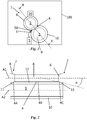
- Fig. 1 and 2 show diagrams of an embodiment of a roller arrangement 1. The dimensions of the elements in these figures may be exaggerated for reasons of illustration.
- the roller arrangement 1 of Fig. 1 comprises a first roller 2, and a second roller 3.
- a nip 4 is provided between the rollers 2, 3.
- a substance feed arrangement 5 is provided for feeding a substance 50 in a direction S, to the nip 4.
- the substance 50 is pressed through the nip 4 by a rotational movement of the rollers 2, 3.
- One of the rollers 2, 3 comprises a resilient outer layer 10.
- Another one of the rollers 2, 3 comprises a stiff outer layer.
- the nip 4 is the area or volume where a stiff roller partly sinks into the resilient outer layer 10 of the other roller, for example where the first roller 2 sinks into the second roller 3, respectively.
- the substance 50 may press through the nip 4 by rotation of the respective rollers 2, 3, being pressurized between the rollers 2, 3.
- the nip 4 comprises a gap, and in operation the resilient outer layer 10 may deform when the substance 50 is pressed through.
- the rollers 2, 3 are arranged to exert an approximately equal pressure onto the substance 50 along the nip 4.
- the roller arrangement 1 comprises a pressure arrangement 20 for pressurizing the substance 50 against a roller 2, 3.
- the pressure arrangement 20 is arranged to press the first roller 2 against the second roller 3.
- the pressure arrangement 20 may comprise a spring, resilient material, an electromotor, an actuator or any other suitable pressure means.
- the rollers 2, 3 have a fixed axis position, and the pressure is exerted by the resilience of the resilient outer layer 10. Not necessarily a separate pressure arrangement 20 is provided.
- the roller arrangement 1 shown in the example of Fig. 1 is part of a substance processing device 100.
- the substance processing device 100 may be a printer and the substance 50 may comprise ink or toner.
- the substance processing device 100 comprises an electrophotographic printer for printing liquid or dry toner onto certain media such as paper. Examples of a printer also include a copy device and a press.
- Fig 2 shows a diagrammatic cross sectional view of the roller arrangement 1 of Fig. 1 along section line II-II.
- the first roller 2 comprises two coned portions 6.
- the coned portions 6 are arranged at the respective ends 4A, 4C of the nip 4, on both sides of a middle portion 4B of the nip 4.
- the coned portions 6 are arranged at the respective end portions 7 of the first roller 2, on both sides of a middle portion 8 of the first roller 2.
- the coned portions 6 are arranged so that a diameter of the respective roller 2 increases towards an end 4A, 4C of the nip 4.
- the surface of the coned portion 6 is inclined under an angle ⁇ , with respect to its central axis.
- the coned portions 6 are inclined with respect to the surface of the second roller 3.
- the coned portions 6 comprise a relatively straight inclination of the surface of the roller 2.
- the coned portions 6 may comprise a convex or concave surface shape. Also combinations or more complex shapes may be applied.
- the second roller 3 comprises a core 9 and a resilient outer layer 10 that is applied around the core 9.
- a relatively equal pressure is exerted onto the substance 50 by the rollers 2, 3, with the aid of the coned portions 6.
- the coned portions 6 may compensate for an increased deformation of the resilient outer layer 10 at the end portions 11 of the resilient outer layer 10, near the ends 4A, 4C of the nip 4.
- the coned shape of the coned portions 6 provides for a additional pressure near the ends 4A, 4C of the nip 4, compensating for the increased deformation that takes place at the end portions 11 of the resilient outer layer 10.
- a relatively equal pressure on the substance 50 in the nip 4 spreads the substance 50 relatively equally along the nip 4.
- the substance 50 comprises a liquid, and the substance feed arrangement 5 is arranged to feed liquid.
- the substance 50 comprises toner and the substance feed arrangement 5 is arranged to feed toner.
- the substance 50 comprises liquid toner and the substance feed arrangement 5 is arranged to feed liquid toner.
- the second roller 3 comprises a developer roller.
- the developer roller has a substantially cylindrical shape, at least along the nip 4.
- a material of the resilient outer layer 10 of the second roller 3 may comprise an elastomer such as polyurethane or rubber. In certain embodiments, at least one coating or additional outer layer may be applied onto the resilient outer layer 10.
- the first roller 2 may comprise a relatively non-resilient or stiff material such as metal. According to the invention, the first roller 2 is provided with the coned portions 6 at each end portion 7 of the roller 2.
- the first roller 2 comprises a squeegee roller, arranged to squeeze liquid toner along the resilient oter layer 10 of the developer roller, with a substantially equal force along the nip 4.
- the coned portions 6 aid in providing the substantially equal force along the nip 4.
- the surface of the coned portion 6 has an angle ⁇ of between approximately 0,2 and approximately 10° with respect to the central axis A1 of the first roller 2.
- the coned portion 6 has an angle ⁇ of between approximately 0,3 and approximately 6° with respect to the central axis A1 of the first roller 2.
- the angle ⁇ of the coned portion 6 may be predetermined based on a desired pressure to be applied to the substance 50 in the nip 4. For example, if the pressure between the rollers 2, 3 is higher, the angle ⁇ may be chosen to be smaller.
- the angle ⁇ may also be chosen to vary along the coned portion 6.
- the coned portion 6 may comprise a concave and/or convex shape.
- a portion of the surface of the coned portion 6 may have an angle ⁇ that exceeds above mentioned range.
- Fig. 3 shows a diagram of an embodiment of a developer arrangement 101 in side view.
- the developer arrangement 101 may be part of an electrophotographic printer.
- the developer arrangement 101 may be arranged for processing liquid or dry toner.
- the shown embodiment may be part of a liquid electrophotographic printer for processing liquid toner 150.
- the developer arrangement 101 comprises a squeegee roller 102 and a developer roller 103.
- a nip 104 is provided between the two rollers 102, 103.
- the developer arrangement 101 comprises an electrode 113 for charging the toner 150, and an inlet 105 for providing the toner 150 to the developer roller 103.
- the electrode 113 may be a main electrode for charging the toner 150.
- Further parts of the developer arrangement 101 include a cleaner roller 114 and a sponge roller 115.
- the developer roller 103 comprises a core 109 and a resilient outer layer 110.
- the resilient outer layer 110 may comprise an elastomeric material such as rubber and/or polyurethane.
- the developer roller 103 transfers fused toner to an image transfer roller 116, of which a part of the surface is shown in Fig. 3 .
- the developer roller 103 may have a charged core 109.
- the core 109 may comprise a chargeable material such as metal.
- the squeegee roller 102 may comprise a chargeable material such as metal.
- Fig. 3 shows an example of a flow direction F of the toner 150. Also examples of a rotational movement direction V2, V3 of the squeegee roller 102 and the developer roller 109, respectively, are shown.
- the toner 150 flows along the electrode 113, where it is charged.
- the toner 150 may be applied to the developer roller 103 because of electric field between the electrode 113 and the developer roller 103.
- the squeegee roller 102 force squeezes the toner 150 against the resilient outer layer 110 of the developer roller 103.
- a thin layer of toner 151 is force squeezed against the developer roller 103. A substantial part of this thin layer 151 is properly fused.
- a top layer 152 that comprises unfused toner 152 may not pass through the nip 104 and may be returned, for example to an ink tank.
- the fused toner 150 may be relatively uniformly spread over the developer roller 103 through the pressurization between the rollers 102, 103, so that it can be transferred to the image transfer roller 116 relatively uniformly. In an example, this may contribute in providing a desired image quality, also near edges of a respective print medium.
- Figs. 4 - 6 show an example of a squeegee roller 102.
- Fig. 4 shows a squeegee roller 102 in front view.
- Fig. 5 shows an end portion 107 of the squeegee roller 102 of Fig. 4 , in front view.
- a diagram of a detail of an engaging end portion 111 of a developer roller 103 is also illustrated in Fig. 5.
- Fig. 6 shows a perspective view of the squeegee roller 102 of Figs. 4 and 5.
- Figs. 4 - 6 illustrate an example of a squeegee roller 102 that is arranged with coned portions 106.
- the coned portions 106 may increase the pressure near respective ends 104A of the nip 104 to prevent that too much unfused toner passes through the nip 104.
- the length L of the squeezing part of the squeegee roller 102 is approximately 338 mm (millimeters).
- the length of the nip 104 may be 338 mm or less.
- the length of the nip 104 may depend on the engaging length of the developer roller 103.
- the length of the developer roller 103 and nip 104 is approximately 332 mm.
- the width of the coned portion 106, as measured along the length of the squeegee roller 102, is approximately 5 mm, with a tolerance of approximately 0,1 mm.
- the coned portion 106 has a width W that is approximately 1,3% of the total length L of the squeezing part of the squeegee roller 102/nip 104.
- each coned portion 106 may have a width W that is between approximately 0,5 and approximately 2 % of the total length L of the squeezing part of the squeegee roller 102/nip 104.
- the shown squeegee roller 102 includes a chamfered portion 117 and an axle 118 near the end portions 107. In an example, these parts 117, 118 extend outside of the nip 104. In certain examples, the coned portions 106 may also partly extend outside of the nip 104.
- the diameter D1 of the squeegee roller 102 is approximately 16 mm at the mid portion 108.
- the diameter D2 of the squeegee roller 102 at the end 107 of the coned portion 106 is approximately 16,5 mm.
- the angle ⁇ of the surface of the coned portion 106 with respect to the central axis, or with respect to the mid portion 108, is approximately 2,86°.
- the angle ⁇ of other squeegee roller examples may be adapted to be within a range of between approximately 0,2 and approximately 5°, or up to approximately 10°.
- the length L may of a respective roller 2, 102 with coned portions 106 may for example be in a range of between approximately 0,1 and approximately 6 m (meters).
- the width W of the coned portion 106 of the respective roller 102 may for example be within a range of between approximately 0,2 and 20% of the total length of the nip 104, or for example within a range of between approximately 0,2 and 5% of the total length of the nip 104.
- roller discussed with reference to Figs. 4 - 6 could be another type of roller than a squeegee roller 102.
- the features and dimensions of the squeegee roller 102 of Figs. 4 - 6 may also apply to other types of rollers 2 with coned portions 6.
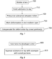
- Fig. 7 shows a flow chart of an example of a method of feeding a substance 50 to a nip 4, 104 between two rollers 2, 3, 102, 103.
- a first block 700 the rollers 2, 3, 102, 103 are rotated.
- the rollers 2, 3, 102, 103 are rotated in a direction V2, V3, respectively.
- the substance 50 is fed to the nip 4, 104.
- the substance 50 comprises toner 150.
- the substance 50 is pressurized between the rollers 2, 3, 102, 103, for spreading a part of the substance 50 along the nip 4, 104.
- the toner 150 is squeezed against the developer roller 103 with the squeegee roller 102.
- an end portion 11, 111 of the resilient outer layer 10, 110 deforms more than a middle portion 12. This may be due to an increased deflection of the resilient material at the end portions 11, 111, where it is not supported by the squeegee roller 2, 102.
- a diameter of the resilient outer layer 10, 110 in the end portion 11, 111 may decrease more in the end portion 11, 111 than in the middle portion 12.
- the coned portion 6, 106 compensates for the increased deformation of the end portion 11, 111, as shown by a fifth block 740.
- the increased diameter of the coned portion 6, 106 may provide for additional pressure in the ends 4A, 4C of the nip 4, 104, so that the pressure on the substance 50, along the entire nip 4, 104, may be more uniform. This allows for a relatively uniform spread of the substance 50 along the nip 4, 104.
- FIG. 8 A further example of a method of feeding a substance 50 to a nip 104 between two rollers 102, 103 is shown in a flow chart in Fig. 8 .
- toner 150 is fed to the developer roller 103.
- the toner 150 is squeezed against the developer roller 103, with the squeegee roller 102, comprising coned portions 106.
- the toner 150 comprises liquid toner.
- use of the coned portions 106 may allow for a relatively uniform spread of the toner 150 over the developer roller 103, and prevent that too much un-fused toner flows through the nip 104 near the ends 104A, 104C of the nip 104.
- Fig. 9 shows another embodiment of a roller arrangement 202, wherein a second roller 203 with a resilient outer layer 210 comprises coned portions 206 at the end portions 211.
- the first roller 202 has a cylindrical shape along the nip 204.
- the coned portions 206 of the second roller 203 may compensate for the increased deformation of its resilient outer layer 210 near its end portions 211 with respect to the deformation in the middle portion 212 of its resilient outer layer 210.
- the roller having the resilient outer layer 10, 110, 210 has a resilient core and/or substantially consists of resilient material.
- the substance 50 may comprise any suitable dry or wet substance, liquid, powder, granular material, medium, mixture, emulsion, etc.
- other processes that comprise feeding a substance 50 to a nip 4, 104, 204 between rollers 2, 102, 202, 3, 103, 203 may be suitable to use a roller arrangement 1, 101, 201 according to this disclosure.
Landscapes
- Physics & Mathematics (AREA)
- General Physics & Mathematics (AREA)
- Wet Developing In Electrophotography (AREA)
Description
- The invention relates to electrophotographic rollers.
- Certain embodiments of roller arrangements are arranged to process substances through nips between their rollers. A substance feed arrangement feeds the substance to the nip.
WO 96/13761 A1 US 6 078 774 A discloses a transfer unit of an electrophotographic printer, wherein one of a transfer roller and a fuser roller is shaped with flared ends and a smaller diameter at its center, and the other roller has a core portion with mating shape to the flared roller and a deformable portion provided around the core portion. The invention provides an electro-photographic roller arrangement according toclaim 1 and a method of feeding substance to a nip between to electro-photographic rollers according toclaim 12. - For the purpose of illustration, certain embodiments of the present invention will now be described with refrence to the accompanying diagrammatic drawings, in which:
-
Fig. 1 shows a diagram of an embodiment of a roller arrangement in a side view; -
Fig. 2 shows a cross sectional view of the embodiment ofFig. 1 , along section line II - II; -
Fig. 3 shows a diagram of an embodiment of a developer arrangement; -
Fig. 4 shows a front view of an embodiment of a squeegee roller; -
Fig. 5 shows a more detailed front view of a coned portion of the embodiment ofFig. 4 ; -
Fig. 6 shows a perspective view of the embodiment of the squeegee roller ofFigs. 4 and 5 ; -
Fig. 7 shows a flow chart of an embodiment of feeding a substance to a nip; -
Fig. 8 shows a flow chart of an embodiment of squeezing liquid toner in a nip; -
Fig. 9 shows a cross sectional diagram of another embodiment of a roller arrangement. - In the following detailed description, reference is made to the accompanying drawings. The embodiments in the description and drawings should be considered illustrative and are not to be considered as limiting to the specific embodiment of element described. Multiple embodiments may be derived from the following description and/or drawings through modification, combination or variation of certain elements. Furthermore, it may be understood that also embodiments or elements that are not literally disclosed may be derived from the description and drawings by a person skilled in the art. The invention is defined by the appended claims.
-
Fig. 1 and 2 show diagrams of an embodiment of aroller arrangement 1. The dimensions of the elements in these figures may be exaggerated for reasons of illustration. Theroller arrangement 1 ofFig. 1 comprises a first roller 2, and a second roller 3. Anip 4 is provided between the rollers 2, 3. A substance feed arrangement 5 is provided for feeding asubstance 50 in a direction S, to thenip 4. Thesubstance 50 is pressed through thenip 4 by a rotational movement of the rollers 2, 3. One of the rollers 2, 3 comprises a resilientouter layer 10. Another one of the rollers 2, 3 comprises a stiff outer layer. - The
nip 4 is the area or volume where a stiff roller partly sinks into the resilientouter layer 10 of the other roller, for example where the first roller 2 sinks into the second roller 3, respectively. In operation, thesubstance 50 may press through thenip 4 by rotation of the respective rollers 2, 3, being pressurized between the rollers 2, 3. In certain embodiments, thenip 4 comprises a gap, and in operation the resilientouter layer 10 may deform when thesubstance 50 is pressed through. In an embodiment, the rollers 2, 3 are arranged to exert an approximately equal pressure onto thesubstance 50 along thenip 4. - For example, the
roller arrangement 1 comprises apressure arrangement 20 for pressurizing thesubstance 50 against a roller 2, 3. In a further example, thepressure arrangement 20 is arranged to press the first roller 2 against the second roller 3. Thepressure arrangement 20 may comprise a spring, resilient material, an electromotor, an actuator or any other suitable pressure means. In other embodiments, the rollers 2, 3 have a fixed axis position, and the pressure is exerted by the resilience of the resilientouter layer 10. Not necessarily aseparate pressure arrangement 20 is provided. - The
roller arrangement 1 shown in the example ofFig. 1 is part of asubstance processing device 100. In a further example, thesubstance processing device 100 may be a printer and thesubstance 50 may comprise ink or toner. In an embodiment thesubstance processing device 100 comprises an electrophotographic printer for printing liquid or dry toner onto certain media such as paper. Examples of a printer also include a copy device and a press. -
Fig 2 shows a diagrammatic cross sectional view of theroller arrangement 1 ofFig. 1 along section line II-II. The first roller 2 comprises twoconed portions 6. Theconed portions 6 are arranged at therespective ends nip 4, on both sides of amiddle portion 4B of thenip 4. In the shown example, theconed portions 6 are arranged at therespective end portions 7 of the first roller 2, on both sides of amiddle portion 8 of the first roller 2. - The
coned portions 6 are arranged so that a diameter of the respective roller 2 increases towards anend nip 4. In the shown example, the surface of theconed portion 6 is inclined under an angle α, with respect to its central axis. In the shown example, theconed portions 6 are inclined with respect to the surface of the second roller 3. In the shown embodiment, theconed portions 6 comprise a relatively straight inclination of the surface of the roller 2. In other embodiments, theconed portions 6 may comprise a convex or concave surface shape. Also combinations or more complex shapes may be applied. - In the shown example, the second roller 3 comprises a
core 9 and a resilientouter layer 10 that is applied around thecore 9. In operation, a relatively equal pressure is exerted onto thesubstance 50 by the rollers 2, 3, with the aid of theconed portions 6. The conedportions 6 may compensate for an increased deformation of the resilientouter layer 10 at theend portions 11 of the resilientouter layer 10, near theends nip 4. In an example, the coned shape of theconed portions 6 provides for a additional pressure near theends nip 4, compensating for the increased deformation that takes place at theend portions 11 of the resilientouter layer 10. A relatively equal pressure on thesubstance 50 in thenip 4, spreads thesubstance 50 relatively equally along thenip 4. - In an embodiment, the
substance 50 comprises a liquid, and the substance feed arrangement 5 is arranged to feed liquid. In another embodiment, thesubstance 50 comprises toner and the substance feed arrangement 5 is arranged to feed toner. In again another embodiment, thesubstance 50 comprises liquid toner and the substance feed arrangement 5 is arranged to feed liquid toner. - In an embodiment, the second roller 3 comprises a developer roller. In a further embodiment, the developer roller has a substantially cylindrical shape, at least along the
nip 4. A material of the resilientouter layer 10 of the second roller 3 may comprise an elastomer such as polyurethane or rubber. In certain embodiments, at least one coating or additional outer layer may be applied onto the resilientouter layer 10. - The first roller 2 may comprise a relatively non-resilient or stiff material such as metal. According to the invention, the first roller 2 is provided with the
coned portions 6 at eachend portion 7 of the roller 2. In an embodiment, the first roller 2 comprises a squeegee roller, arranged to squeeze liquid toner along theresilient oter layer 10 of the developer roller, with a substantially equal force along thenip 4. Theconed portions 6 aid in providing the substantially equal force along thenip 4. - In an embodiment, the surface of the
coned portion 6 has an angle α of between approximately 0,2 and approximately 10° with respect to the central axis A1 of the first roller 2. For example, theconed portion 6 has an angle α of between approximately 0,3 and approximately 6° with respect to the central axis A1 of the first roller 2. For example, the angle α of theconed portion 6 may be predetermined based on a desired pressure to be applied to thesubstance 50 in thenip 4. For example, if the pressure between the rollers 2, 3 is higher, the angle α may be chosen to be smaller. The angle α may also be chosen to vary along theconed portion 6. For example, theconed portion 6 may comprise a concave and/or convex shape. In an embodiment, a portion of the surface of theconed portion 6 may have an angle α that exceeds above mentioned range. -
Fig. 3 shows a diagram of an embodiment of adeveloper arrangement 101 in side view. Thedeveloper arrangement 101 may be part of an electrophotographic printer. Thedeveloper arrangement 101 may be arranged for processing liquid or dry toner. The shown embodiment may be part of a liquid electrophotographic printer for processingliquid toner 150. - The
developer arrangement 101 comprises asqueegee roller 102 and adeveloper roller 103. Anip 104 is provided between the tworollers developer arrangement 101 comprises an electrode 113 for charging thetoner 150, and aninlet 105 for providing thetoner 150 to thedeveloper roller 103. The electrode 113 may be a main electrode for charging thetoner 150. Further parts of thedeveloper arrangement 101 include acleaner roller 114 and asponge roller 115. Thedeveloper roller 103 comprises acore 109 and a resilientouter layer 110. The resilientouter layer 110 may comprise an elastomeric material such as rubber and/or polyurethane. In a further embodiment, thedeveloper roller 103 transfers fused toner to animage transfer roller 116, of which a part of the surface is shown inFig. 3 . - Several parts of the
developer arrangement 101 are charged for processing thetoner 150. In certain illustrative examples, at least a part of the electrode 113 is charged with approximately -1500 Volts, at least a part of thecleaner roller 114 with approximately -240 Volts, at least a part of thedeveloper roller 103 with approximately -500 Volts, at least a part of thesqueegee roller 102 with approximately -800 Volts, and at least a part of theimage transfer roller 116 with approximately -350 to -600 Volts. Thedeveloper roller 103 may have a chargedcore 109. Thecore 109 may comprise a chargeable material such as metal. Thesqueegee roller 102 may comprise a chargeable material such as metal. -
Fig. 3 shows an example of a flow direction F of thetoner 150. Also examples of a rotational movement direction V2, V3 of thesqueegee roller 102 and thedeveloper roller 109, respectively, are shown. Thetoner 150 flows along the electrode 113, where it is charged. Thetoner 150 may be applied to thedeveloper roller 103 because of electric field between the electrode 113 and thedeveloper roller 103. Thesqueegee roller 102 force squeezes thetoner 150 against the resilientouter layer 110 of thedeveloper roller 103. For example, a thin layer oftoner 151 is force squeezed against thedeveloper roller 103. A substantial part of thisthin layer 151 is properly fused. Atop layer 152 that comprisesunfused toner 152 may not pass through thenip 104 and may be returned, for example to an ink tank. The fusedtoner 150 may be relatively uniformly spread over thedeveloper roller 103 through the pressurization between therollers image transfer roller 116 relatively uniformly. In an example, this may contribute in providing a desired image quality, also near edges of a respective print medium. -
Figs. 4 - 6 show an example of asqueegee roller 102.Fig. 4 shows asqueegee roller 102 in front view.Fig. 5 shows anend portion 107 of thesqueegee roller 102 ofFig. 4 , in front view. For illustration, a diagram of a detail of anengaging end portion 111 of adeveloper roller 103 is also illustrated inFig. 5. Fig. 6 shows a perspective view of thesqueegee roller 102 ofFigs. 4 and 5. Figs. 4 - 6 illustrate an example of asqueegee roller 102 that is arranged with conedportions 106. For example, in operation, theconed portions 106 may increase the pressure nearrespective ends 104A of thenip 104 to prevent that too much unfused toner passes through thenip 104. - In the shown example the length L of the squeezing part of the
squeegee roller 102 is approximately 338 mm (millimeters). For this embodiment, the length of thenip 104 may be 338 mm or less. For example, the length of thenip 104 may depend on the engaging length of thedeveloper roller 103. For example, the length of thedeveloper roller 103 and nip 104 is approximately 332 mm. In the shown example, the width of theconed portion 106, as measured along the length of thesqueegee roller 102, is approximately 5 mm, with a tolerance of approximately 0,1 mm. In the shown example, theconed portion 106 has a width W that is approximately 1,3% of the total length L of the squeezing part of thesqueegee roller 102/nip 104. For example, eachconed portion 106 may have a width W that is between approximately 0,5 and approximately 2 % of the total length L of the squeezing part of thesqueegee roller 102/nip 104. The shownsqueegee roller 102 includes a chamferedportion 117 and anaxle 118 near theend portions 107. In an example, theseparts nip 104. In certain examples, theconed portions 106 may also partly extend outside of thenip 104. - In the shown example, the diameter D1 of the
squeegee roller 102 is approximately 16 mm at themid portion 108. The diameter D2 of thesqueegee roller 102 at theend 107 of theconed portion 106 is approximately 16,5 mm. The angle α of the surface of theconed portion 106 with respect to the central axis, or with respect to themid portion 108, is approximately 2,86°. For example, the angle α of other squeegee roller examples may be adapted to be within a range of between approximately 0,2 and approximately 5°, or up to approximately 10°. - In other embodiments the length L may of a
respective roller 2, 102 withconed portions 106 may for example be in a range of between approximately 0,1 and approximately 6 m (meters). The width W of theconed portion 106 of therespective roller 102 may for example be within a range of between approximately 0,2 and 20% of the total length of thenip 104, or for example within a range of between approximately 0,2 and 5% of the total length of thenip 104. - It is noted that the roller discussed with reference to
Figs. 4 - 6 could be another type of roller than asqueegee roller 102. The features and dimensions of thesqueegee roller 102 ofFigs. 4 - 6 may also apply to other types of rollers 2 withconed portions 6. -
Fig. 7 shows a flow chart of an example of a method of feeding asubstance 50 to a nip 4, 104 between tworollers first block 700, therollers rollers second block 710, thesubstance 50 is fed to the nip 4, 104. For example, thesubstance 50 comprisestoner 150. In athird block 720, thesubstance 50 is pressurized between therollers substance 50 along thenip toner 150 is squeezed against thedeveloper roller 103 with thesqueegee roller 102. In afourth block 730, anend portion outer layer middle portion 12. This may be due to an increased deflection of the resilient material at theend portions squeegee roller 2, 102. For example, a diameter of the resilientouter layer end portion end portion middle portion 12. Theconed portion end portion fifth block 740. The increased diameter of theconed portion ends nip substance 50, along the entire nip 4, 104, may be more uniform. This allows for a relatively uniform spread of thesubstance 50 along thenip - A further example of a method of feeding a
substance 50 to a nip 104 between tworollers Fig. 8 . In afirst block 800,toner 150 is fed to thedeveloper roller 103. In asecond block 810, thetoner 150 is squeezed against thedeveloper roller 103, with thesqueegee roller 102, comprisingconed portions 106. In an example, thetoner 150 comprises liquid toner. In this embodiment, use of theconed portions 106 may allow for a relatively uniform spread of thetoner 150 over thedeveloper roller 103, and prevent that too much un-fused toner flows through thenip 104 near theends 104A, 104C of thenip 104. -
Fig. 9 shows another embodiment of aroller arrangement 202, wherein asecond roller 203 with a resilientouter layer 210 comprises conedportions 206 at theend portions 211. Thefirst roller 202 has a cylindrical shape along thenip 204. In such embodiment theconed portions 206 of thesecond roller 203 may compensate for the increased deformation of its resilientouter layer 210 near itsend portions 211 with respect to the deformation in themiddle portion 212 of its resilientouter layer 210. - In certain embodiments, the roller having the resilient
outer layer - In certain embodiments, the
substance 50 may comprise any suitable dry or wet substance, liquid, powder, granular material, medium, mixture, emulsion, etc. In addition to developing, fusing and/or printing, other processes that comprise feeding asubstance 50 to a nip 4, 104, 204 betweenrollers roller arrangement - The above description is not intended to be exhaustive or to limit the invention to the embodiments disclosed. Other variations to the disclosed embodiments can be understood and effected by those skilled in the art in practicing the claimed invention, from a study of the drawings, the disclosure, and the appended claims. The indefinite article "a" or "an" does not exclude a plurality, while a reference to a certain number of elements does not exclude the possibility of having more or less elements. A single unit may fulfil the functions of several items recited in the disclosure, and vice versa several items may fulfil the function of one unit. The invention is defined by the appendedclaims.
Claims (14)
- Electrophotographic roller arrangement (1; 101; 201), comprising two rollers (2, 3; 102, 103; 202, 203), one of the rollers (3;103;203) having a resilient outer layer (10; 110; 210) extending substantially the length thereof,
a nip (4; 104; 204) between the rollers (2, 3; 102, 103; 202, 203), and
a substance feed arrangement (5) for feeding substance (50) to the nip (4; 104; 204), wherein
the rollers (2, 3; 102, 103; 202, 203) are arranged to spread the substance (50) along the nip (4; 104; 204),
a respective coned portion (6; 106; 206) is provided at each end of one of the rollers (2;102;203) near an end of the nip (4; 104; 204), wherein the roller (2;102;203) has a substantially cylindrical shape along the nip (4; 104; 204) between said coned portions (6; 106; 206), and
the other one of the rollers (3; 103; 203) has a substantially cylindrical shape along the nip (4; 104; 204),
characterized in that the coned portions (6; 106; 206) are arranged to provide additional pressure on end portions (11; 111; 211) of the resilient outer layer (10; 110; 210) such that a relatively equal pressure is exerted onto the substance (50) by the rollers (2, 3; 102, 103; 202, 203) along the length of the nip (4; 104; 204), compensating for the increased deformation that takes place at the end portions (11; 111; 211) of the resilient outer layer (10; 110; 210). - Roller arrangement (1; 101; 201) according to claim 1, wherein each coned portion (6; 106; 206) has an inclined surface with respect to the opposite roller (3;103;202).
- Roller arrangement (1; 101; 201) according to claim 1, wherein the substance feed arrangeent (5) is arranged to feed liquid.
- Roller arrangement (1; 101; 201) according to claim 1, wherein the substance feed arrangement (5) is arranged to feed toner.
- Roller arrangement (1; 101; 201) according to claim 1, wherein the roller (3; 103; 203) with the resilient outer layer (10; 110; 210) is a developer roller.
- Roller arrangement (1; 101; 201) according to claim 1, wherein the resilient outer layer (10; 110; 210) comprises an elastomer.
- Roller arrangement (1; 101; 201) according to claim 1, wherein one of the rollers (2, 3; 102, 103; 202, 203) comprises a squeegee roller, and the squeegee roller is provided with said coned portions (6; 106; 206) at each end.
- Roller arrangement (1; 101; 201) according to claim 1, wherein each coned portion (6; 106; 206) has an angle of between approximately 0,2 and approximately 10° with respect to a central axis of the respective roller (2, 3; 102, 103; 202, 203).
- Roller arrangement (1; 101; 201) according to claim 8 wherein the nip (4; 104; 204) comprises a middle portion and two end portions, and the coned portions (6; 106; 206) are arranged to compress resilient outer layer (10; 110; 210) in the region of the end portions.
- Developer arrangement comprising a roller arrangement (1; 101; 201) according to claim 1.
- Electro-photographic printer comprising a roller arrangement (1; 101; 201) according to claim 1.
- Method of feeding substance (50) to a nip (4; 104; 204) between two electrophotographic rollers (2, 3; 102, 103; 202, 203), wherein one of the rollers (3; 103; 203) has a resilient outer layer (10; 110; 210) extending substantially the length thereof, and a respective coned portion (6; 106; 206) is provided at each end of one of the rollers (2;102;203), near an end of the nip (4; 104; 204), wherein the roller (2;102;203) has a substantially cylindrical shape along the nip (4; 104; 204) between said coned portions (6; 106; 206), and wherein the other one of the rollers (3; 103; 203) has a substantially cylindrical shape along the nip (4; 104; 204), the method comprising
feeding (710; 800) the substance (50) to the nip (4; 104; 204),
and, characterized in that, by virtue of arranging the coned portion (6; 106; 206) to provide additional pressure on an end portion (11; 111; 211) of the resilient outer layer (10; 110; 210), exerting (720; 810) a relatively equal pressure onto the substance (50) with the rollers (2, 3; 102, 103; 202, 203) for spreading the substance (50) along the nip (4; 104; 204), compensating for the increased deformation that takes place at the end portions (11; 111; 211) of the resilient outer layer (10; 110; 210). - Method according to claim 12, wherein
the substance (50) comprises toner,
one of the rollers (3; 103; 203) comprises a developer roller,
one of the rollers (2; 102; 202) comprises a squeegee roller, the method comprising squeezing (720; 810) the toner against the developer roller with the squeegee roller. - Method according to claim 12, wherein the substance (50) comprises liquid toner.
Applications Claiming Priority (1)
| Application Number | Priority Date | Filing Date | Title |
|---|---|---|---|
| PCT/EP2011/054892 WO2012130295A1 (en) | 2011-03-30 | 2011-03-30 | Rollers |
Publications (2)
| Publication Number | Publication Date |
|---|---|
| EP2691816A1 EP2691816A1 (en) | 2014-02-05 |
| EP2691816B1 true EP2691816B1 (en) | 2021-04-28 |
Family
ID=44148777
Family Applications (1)
| Application Number | Title | Priority Date | Filing Date |
|---|---|---|---|
| EP11713725.7A Active EP2691816B1 (en) | 2011-03-30 | 2011-03-30 | Electrophotographic roller arrangement |
Country Status (4)
| Country | Link |
|---|---|
| US (1) | US9244388B2 (en) |
| EP (1) | EP2691816B1 (en) |
| CN (1) | CN103534651B (en) |
| WO (1) | WO2012130295A1 (en) |
Families Citing this family (1)
| Publication number | Priority date | Publication date | Assignee | Title |
|---|---|---|---|---|
| JP7318266B2 (en) | 2019-03-28 | 2023-08-01 | ブラザー工業株式会社 | developer cartridge |
Citations (1)
| Publication number | Priority date | Publication date | Assignee | Title |
|---|---|---|---|---|
| US5854960A (en) * | 1994-10-28 | 1998-12-29 | Indigo N.V. | Squeegee roller for imaging systems |
Family Cites Families (6)
| Publication number | Priority date | Publication date | Assignee | Title |
|---|---|---|---|---|
| US5689788A (en) * | 1996-03-22 | 1997-11-18 | Xerox Corporation | Heat and pressure roll fuser with substantially uniform velocity |
| CN1148613C (en) * | 1998-01-26 | 2004-05-05 | 株式会社理光 | Transfer roller and image-forming device |
| KR100335429B1 (en) * | 1998-09-19 | 2002-08-21 | 삼성전자 주식회사 | Transfer unit of electrophotographic printer |
| JP3986476B2 (en) * | 2003-07-09 | 2007-10-03 | 株式会社沖データ | Development device |
| KR100690102B1 (en) | 2004-03-31 | 2007-03-09 | 가부시키가이샤 리코 | Developing apparatus, process cartridge and image forming apparatus using this developing apparatus |
| JP2010145899A (en) | 2008-12-22 | 2010-07-01 | Seiko Epson Corp | Latent image carrier unit and image forming apparatus |
-
2011
- 2011-03-30 EP EP11713725.7A patent/EP2691816B1/en active Active
- 2011-03-30 US US14/007,104 patent/US9244388B2/en not_active Expired - Fee Related
- 2011-03-30 WO PCT/EP2011/054892 patent/WO2012130295A1/en not_active Ceased
- 2011-03-30 CN CN201180069797.5A patent/CN103534651B/en not_active Expired - Fee Related
Patent Citations (1)
| Publication number | Priority date | Publication date | Assignee | Title |
|---|---|---|---|---|
| US5854960A (en) * | 1994-10-28 | 1998-12-29 | Indigo N.V. | Squeegee roller for imaging systems |
Also Published As
| Publication number | Publication date |
|---|---|
| CN103534651A (en) | 2014-01-22 |
| US9244388B2 (en) | 2016-01-26 |
| CN103534651B (en) | 2017-03-22 |
| WO2012130295A1 (en) | 2012-10-04 |
| US20140023400A1 (en) | 2014-01-23 |
| EP2691816A1 (en) | 2014-02-05 |
Similar Documents
| Publication | Publication Date | Title |
|---|---|---|
| CN103970001B (en) | Fixing device and image processing system | |
| US7664449B2 (en) | Fixing apparatus and image forming apparatus | |
| CN104204962A (en) | Liquid electrophotography ink developer | |
| US8391766B2 (en) | Fixing device and image forming apparatus incorporating same | |
| US9250572B2 (en) | Ink developer unit, and sealing device usable with ink developer unit | |
| US7054587B2 (en) | Image forming apparatus for recording on two sides in a single pass | |
| CN110412846A (en) | Imaging device | |
| CN101211151B (en) | Fixing device and image forming apparatus | |
| US8588667B2 (en) | Transfer NIP for an electrophotographic device, and methods of making and using same | |
| US20120237275A1 (en) | Apparatus and method to control media wrinkling through roll flaring | |
| US9244388B2 (en) | Roller with non-uniform diameter | |
| US20120134726A1 (en) | Image Forming Apparatus | |
| US9519257B2 (en) | Cleaning device and image forming apparatus incorporating same | |
| US20170269538A1 (en) | Cleaning device and image forming apparatus including the same | |
| US20110200372A1 (en) | Fixation device and image formation apparatus | |
| US7734240B2 (en) | Fusers, printing apparatuses and methods, and methods of fusing toner on media | |
| EP2149822B1 (en) | Liquid delivery systems, fuser assemblies, printing apparatuses and methods of delivering release agents to fusing imaging surfaces | |
| JP6357885B2 (en) | Image forming apparatus | |
| CN103009797B (en) | Roller and indirect imaging device is run through for what there is the indirect printing machine of the image-receptive component of thin-walled | |
| EP3585621B1 (en) | Print agent application assemblies | |
| JP5516334B2 (en) | Image forming apparatus | |
| JP3624932B2 (en) | Image forming apparatus | |
| JP2016186574A (en) | Cleaning device and image forming apparatus | |
| CN110192156A (en) | Developer roll for liquid electrophotographic printing | |
| JP5446181B2 (en) | Fixing apparatus and image forming apparatus |
Legal Events
| Date | Code | Title | Description |
|---|---|---|---|
| PUAI | Public reference made under article 153(3) epc to a published international application that has entered the european phase |
Free format text: ORIGINAL CODE: 0009012 |
|
| 17P | Request for examination filed |
Effective date: 20130930 |
|
| AK | Designated contracting states |
Kind code of ref document: A1 Designated state(s): AL AT BE BG CH CY CZ DE DK EE ES FI FR GB GR HR HU IE IS IT LI LT LU LV MC MK MT NL NO PL PT RO RS SE SI SK SM TR |
|
| RIN1 | Information on inventor provided before grant (corrected) |
Inventor name: BERGER, SHACHAR Inventor name: COHEN, ZVIKA Inventor name: LEVINTANT, ORAN |
|
| DAX | Request for extension of the european patent (deleted) | ||
| RAP1 | Party data changed (applicant data changed or rights of an application transferred) |
Owner name: HP INDIGO B.V. |
|
| STAA | Information on the status of an ep patent application or granted ep patent |
Free format text: STATUS: EXAMINATION IS IN PROGRESS |
|
| 17Q | First examination report despatched |
Effective date: 20180926 |
|
| GRAP | Despatch of communication of intention to grant a patent |
Free format text: ORIGINAL CODE: EPIDOSNIGR1 |
|
| STAA | Information on the status of an ep patent application or granted ep patent |
Free format text: STATUS: GRANT OF PATENT IS INTENDED |
|
| INTG | Intention to grant announced |
Effective date: 20210115 |
|
| GRAS | Grant fee paid |
Free format text: ORIGINAL CODE: EPIDOSNIGR3 |
|
| GRAA | (expected) grant |
Free format text: ORIGINAL CODE: 0009210 |
|
| STAA | Information on the status of an ep patent application or granted ep patent |
Free format text: STATUS: THE PATENT HAS BEEN GRANTED |
|
| RIN1 | Information on inventor provided before grant (corrected) |
Inventor name: BERGER, SHACHAR Inventor name: COHEN, ZVIKA Inventor name: LEVINTANT, ORAN |
|
| AK | Designated contracting states |
Kind code of ref document: B1 Designated state(s): AL AT BE BG CH CY CZ DE DK EE ES FI FR GB GR HR HU IE IS IT LI LT LU LV MC MK MT NL NO PL PT RO RS SE SI SK SM TR |
|
| REG | Reference to a national code |
Ref country code: GB Ref legal event code: FG4D |
|
| REG | Reference to a national code |
Ref country code: CH Ref legal event code: EP |
|
| REG | Reference to a national code |
Ref country code: DE Ref legal event code: R096 Ref document number: 602011070812 Country of ref document: DE |
|
| REG | Reference to a national code |
Ref country code: AT Ref legal event code: REF Ref document number: 1387765 Country of ref document: AT Kind code of ref document: T Effective date: 20210515 |
|
| REG | Reference to a national code |
Ref country code: IE Ref legal event code: FG4D |
|
| REG | Reference to a national code |
Ref country code: LT Ref legal event code: MG9D |
|
| REG | Reference to a national code |
Ref country code: AT Ref legal event code: MK05 Ref document number: 1387765 Country of ref document: AT Kind code of ref document: T Effective date: 20210428 |
|
| PG25 | Lapsed in a contracting state [announced via postgrant information from national office to epo] |
Ref country code: BG Free format text: LAPSE BECAUSE OF FAILURE TO SUBMIT A TRANSLATION OF THE DESCRIPTION OR TO PAY THE FEE WITHIN THE PRESCRIBED TIME-LIMIT Effective date: 20210728 Ref country code: AT Free format text: LAPSE BECAUSE OF FAILURE TO SUBMIT A TRANSLATION OF THE DESCRIPTION OR TO PAY THE FEE WITHIN THE PRESCRIBED TIME-LIMIT Effective date: 20210428 Ref country code: HR Free format text: LAPSE BECAUSE OF FAILURE TO SUBMIT A TRANSLATION OF THE DESCRIPTION OR TO PAY THE FEE WITHIN THE PRESCRIBED TIME-LIMIT Effective date: 20210428 Ref country code: FI Free format text: LAPSE BECAUSE OF FAILURE TO SUBMIT A TRANSLATION OF THE DESCRIPTION OR TO PAY THE FEE WITHIN THE PRESCRIBED TIME-LIMIT Effective date: 20210428 Ref country code: NL Free format text: LAPSE BECAUSE OF FAILURE TO SUBMIT A TRANSLATION OF THE DESCRIPTION OR TO PAY THE FEE WITHIN THE PRESCRIBED TIME-LIMIT Effective date: 20210428 Ref country code: LT Free format text: LAPSE BECAUSE OF FAILURE TO SUBMIT A TRANSLATION OF THE DESCRIPTION OR TO PAY THE FEE WITHIN THE PRESCRIBED TIME-LIMIT Effective date: 20210428 |
|
| PG25 | Lapsed in a contracting state [announced via postgrant information from national office to epo] |
Ref country code: ES Free format text: LAPSE BECAUSE OF FAILURE TO SUBMIT A TRANSLATION OF THE DESCRIPTION OR TO PAY THE FEE WITHIN THE PRESCRIBED TIME-LIMIT Effective date: 20210428 Ref country code: NO Free format text: LAPSE BECAUSE OF FAILURE TO SUBMIT A TRANSLATION OF THE DESCRIPTION OR TO PAY THE FEE WITHIN THE PRESCRIBED TIME-LIMIT Effective date: 20210728 Ref country code: PT Free format text: LAPSE BECAUSE OF FAILURE TO SUBMIT A TRANSLATION OF THE DESCRIPTION OR TO PAY THE FEE WITHIN THE PRESCRIBED TIME-LIMIT Effective date: 20210830 Ref country code: PL Free format text: LAPSE BECAUSE OF FAILURE TO SUBMIT A TRANSLATION OF THE DESCRIPTION OR TO PAY THE FEE WITHIN THE PRESCRIBED TIME-LIMIT Effective date: 20210428 Ref country code: IS Free format text: LAPSE BECAUSE OF FAILURE TO SUBMIT A TRANSLATION OF THE DESCRIPTION OR TO PAY THE FEE WITHIN THE PRESCRIBED TIME-LIMIT Effective date: 20210828 Ref country code: LV Free format text: LAPSE BECAUSE OF FAILURE TO SUBMIT A TRANSLATION OF THE DESCRIPTION OR TO PAY THE FEE WITHIN THE PRESCRIBED TIME-LIMIT Effective date: 20210428 Ref country code: GR Free format text: LAPSE BECAUSE OF FAILURE TO SUBMIT A TRANSLATION OF THE DESCRIPTION OR TO PAY THE FEE WITHIN THE PRESCRIBED TIME-LIMIT Effective date: 20210729 Ref country code: RS Free format text: LAPSE BECAUSE OF FAILURE TO SUBMIT A TRANSLATION OF THE DESCRIPTION OR TO PAY THE FEE WITHIN THE PRESCRIBED TIME-LIMIT Effective date: 20210428 Ref country code: SE Free format text: LAPSE BECAUSE OF FAILURE TO SUBMIT A TRANSLATION OF THE DESCRIPTION OR TO PAY THE FEE WITHIN THE PRESCRIBED TIME-LIMIT Effective date: 20210428 |
|
| REG | Reference to a national code |
Ref country code: NL Ref legal event code: MP Effective date: 20210428 |
|
| PG25 | Lapsed in a contracting state [announced via postgrant information from national office to epo] |
Ref country code: RO Free format text: LAPSE BECAUSE OF FAILURE TO SUBMIT A TRANSLATION OF THE DESCRIPTION OR TO PAY THE FEE WITHIN THE PRESCRIBED TIME-LIMIT Effective date: 20210428 Ref country code: EE Free format text: LAPSE BECAUSE OF FAILURE TO SUBMIT A TRANSLATION OF THE DESCRIPTION OR TO PAY THE FEE WITHIN THE PRESCRIBED TIME-LIMIT Effective date: 20210428 Ref country code: DK Free format text: LAPSE BECAUSE OF FAILURE TO SUBMIT A TRANSLATION OF THE DESCRIPTION OR TO PAY THE FEE WITHIN THE PRESCRIBED TIME-LIMIT Effective date: 20210428 Ref country code: CZ Free format text: LAPSE BECAUSE OF FAILURE TO SUBMIT A TRANSLATION OF THE DESCRIPTION OR TO PAY THE FEE WITHIN THE PRESCRIBED TIME-LIMIT Effective date: 20210428 Ref country code: SM Free format text: LAPSE BECAUSE OF FAILURE TO SUBMIT A TRANSLATION OF THE DESCRIPTION OR TO PAY THE FEE WITHIN THE PRESCRIBED TIME-LIMIT Effective date: 20210428 Ref country code: SK Free format text: LAPSE BECAUSE OF FAILURE TO SUBMIT A TRANSLATION OF THE DESCRIPTION OR TO PAY THE FEE WITHIN THE PRESCRIBED TIME-LIMIT Effective date: 20210428 |
|
| REG | Reference to a national code |
Ref country code: DE Ref legal event code: R097 Ref document number: 602011070812 Country of ref document: DE |
|
| PLBE | No opposition filed within time limit |
Free format text: ORIGINAL CODE: 0009261 |
|
| STAA | Information on the status of an ep patent application or granted ep patent |
Free format text: STATUS: NO OPPOSITION FILED WITHIN TIME LIMIT |
|
| 26N | No opposition filed |
Effective date: 20220131 |
|
| PGFP | Annual fee paid to national office [announced via postgrant information from national office to epo] |
Ref country code: GB Payment date: 20220225 Year of fee payment: 12 Ref country code: DE Payment date: 20220217 Year of fee payment: 12 |
|
| PG25 | Lapsed in a contracting state [announced via postgrant information from national office to epo] |
Ref country code: IS Free format text: LAPSE BECAUSE OF FAILURE TO SUBMIT A TRANSLATION OF THE DESCRIPTION OR TO PAY THE FEE WITHIN THE PRESCRIBED TIME-LIMIT Effective date: 20210828 Ref country code: AL Free format text: LAPSE BECAUSE OF FAILURE TO SUBMIT A TRANSLATION OF THE DESCRIPTION OR TO PAY THE FEE WITHIN THE PRESCRIBED TIME-LIMIT Effective date: 20210428 |
|
| PGFP | Annual fee paid to national office [announced via postgrant information from national office to epo] |
Ref country code: FR Payment date: 20220221 Year of fee payment: 12 |
|
| PG25 | Lapsed in a contracting state [announced via postgrant information from national office to epo] |
Ref country code: IT Free format text: LAPSE BECAUSE OF FAILURE TO SUBMIT A TRANSLATION OF THE DESCRIPTION OR TO PAY THE FEE WITHIN THE PRESCRIBED TIME-LIMIT Effective date: 20210428 |
|
| PG25 | Lapsed in a contracting state [announced via postgrant information from national office to epo] |
Ref country code: MC Free format text: LAPSE BECAUSE OF FAILURE TO SUBMIT A TRANSLATION OF THE DESCRIPTION OR TO PAY THE FEE WITHIN THE PRESCRIBED TIME-LIMIT Effective date: 20210428 |
|
| REG | Reference to a national code |
Ref country code: CH Ref legal event code: PL |
|
| REG | Reference to a national code |
Ref country code: BE Ref legal event code: MM Effective date: 20220331 |
|
| PG25 | Lapsed in a contracting state [announced via postgrant information from national office to epo] |
Ref country code: LU Free format text: LAPSE BECAUSE OF NON-PAYMENT OF DUE FEES Effective date: 20220330 Ref country code: LI Free format text: LAPSE BECAUSE OF NON-PAYMENT OF DUE FEES Effective date: 20220331 Ref country code: IE Free format text: LAPSE BECAUSE OF NON-PAYMENT OF DUE FEES Effective date: 20220330 Ref country code: CH Free format text: LAPSE BECAUSE OF NON-PAYMENT OF DUE FEES Effective date: 20220331 |
|
| PG25 | Lapsed in a contracting state [announced via postgrant information from national office to epo] |
Ref country code: BE Free format text: LAPSE BECAUSE OF NON-PAYMENT OF DUE FEES Effective date: 20220331 |
|
| REG | Reference to a national code |
Ref country code: DE Ref legal event code: R119 Ref document number: 602011070812 Country of ref document: DE |
|
| GBPC | Gb: european patent ceased through non-payment of renewal fee |
Effective date: 20230330 |
|
| PG25 | Lapsed in a contracting state [announced via postgrant information from national office to epo] |
Ref country code: GB Free format text: LAPSE BECAUSE OF NON-PAYMENT OF DUE FEES Effective date: 20230330 |
|
| PG25 | Lapsed in a contracting state [announced via postgrant information from national office to epo] |
Ref country code: GB Free format text: LAPSE BECAUSE OF NON-PAYMENT OF DUE FEES Effective date: 20230330 Ref country code: FR Free format text: LAPSE BECAUSE OF NON-PAYMENT OF DUE FEES Effective date: 20230331 Ref country code: DE Free format text: LAPSE BECAUSE OF NON-PAYMENT OF DUE FEES Effective date: 20231003 |
|
| PG25 | Lapsed in a contracting state [announced via postgrant information from national office to epo] |
Ref country code: HU Free format text: LAPSE BECAUSE OF FAILURE TO SUBMIT A TRANSLATION OF THE DESCRIPTION OR TO PAY THE FEE WITHIN THE PRESCRIBED TIME-LIMIT; INVALID AB INITIO Effective date: 20110330 |
|
| PG25 | Lapsed in a contracting state [announced via postgrant information from national office to epo] |
Ref country code: MK Free format text: LAPSE BECAUSE OF FAILURE TO SUBMIT A TRANSLATION OF THE DESCRIPTION OR TO PAY THE FEE WITHIN THE PRESCRIBED TIME-LIMIT Effective date: 20210428 Ref country code: CY Free format text: LAPSE BECAUSE OF FAILURE TO SUBMIT A TRANSLATION OF THE DESCRIPTION OR TO PAY THE FEE WITHIN THE PRESCRIBED TIME-LIMIT Effective date: 20210428 |
|
| PG25 | Lapsed in a contracting state [announced via postgrant information from national office to epo] |
Ref country code: MT Free format text: LAPSE BECAUSE OF FAILURE TO SUBMIT A TRANSLATION OF THE DESCRIPTION OR TO PAY THE FEE WITHIN THE PRESCRIBED TIME-LIMIT Effective date: 20210428 |
|
| PG25 | Lapsed in a contracting state [announced via postgrant information from national office to epo] |
Ref country code: TR Free format text: LAPSE BECAUSE OF FAILURE TO SUBMIT A TRANSLATION OF THE DESCRIPTION OR TO PAY THE FEE WITHIN THE PRESCRIBED TIME-LIMIT Effective date: 20210428 |