EP2691225B1 - Blow mould - Google Patents
Blow mould Download PDFInfo
- Publication number
- EP2691225B1 EP2691225B1 EP12717229.4A EP12717229A EP2691225B1 EP 2691225 B1 EP2691225 B1 EP 2691225B1 EP 12717229 A EP12717229 A EP 12717229A EP 2691225 B1 EP2691225 B1 EP 2691225B1
- Authority
- EP
- European Patent Office
- Prior art keywords
- mould
- holder
- locking
- blow
- mould holder
- Prior art date
- Legal status (The legal status is an assumption and is not a legal conclusion. Google has not performed a legal analysis and makes no representation as to the accuracy of the status listed.)
- Active
Links
Images






Classifications
-
- B—PERFORMING OPERATIONS; TRANSPORTING
- B29—WORKING OF PLASTICS; WORKING OF SUBSTANCES IN A PLASTIC STATE IN GENERAL
- B29C—SHAPING OR JOINING OF PLASTICS; SHAPING OF MATERIAL IN A PLASTIC STATE, NOT OTHERWISE PROVIDED FOR; AFTER-TREATMENT OF THE SHAPED PRODUCTS, e.g. REPAIRING
- B29C49/00—Blow-moulding, i.e. blowing a preform or parison to a desired shape within a mould; Apparatus therefor
- B29C49/42—Component parts, details or accessories; Auxiliary operations
- B29C49/56—Opening, closing or clamping means
-
- B—PERFORMING OPERATIONS; TRANSPORTING
- B29—WORKING OF PLASTICS; WORKING OF SUBSTANCES IN A PLASTIC STATE IN GENERAL
- B29C—SHAPING OR JOINING OF PLASTICS; SHAPING OF MATERIAL IN A PLASTIC STATE, NOT OTHERWISE PROVIDED FOR; AFTER-TREATMENT OF THE SHAPED PRODUCTS, e.g. REPAIRING
- B29C33/00—Moulds or cores; Details thereof or accessories therefor
- B29C33/30—Mounting, exchanging or centering
- B29C33/305—Mounting of moulds or mould support plates
-
- B—PERFORMING OPERATIONS; TRANSPORTING
- B29—WORKING OF PLASTICS; WORKING OF SUBSTANCES IN A PLASTIC STATE IN GENERAL
- B29C—SHAPING OR JOINING OF PLASTICS; SHAPING OF MATERIAL IN A PLASTIC STATE, NOT OTHERWISE PROVIDED FOR; AFTER-TREATMENT OF THE SHAPED PRODUCTS, e.g. REPAIRING
- B29C49/00—Blow-moulding, i.e. blowing a preform or parison to a desired shape within a mould; Apparatus therefor
- B29C49/42—Component parts, details or accessories; Auxiliary operations
- B29C49/48—Moulds
-
- B—PERFORMING OPERATIONS; TRANSPORTING
- B29—WORKING OF PLASTICS; WORKING OF SUBSTANCES IN A PLASTIC STATE IN GENERAL
- B29C—SHAPING OR JOINING OF PLASTICS; SHAPING OF MATERIAL IN A PLASTIC STATE, NOT OTHERWISE PROVIDED FOR; AFTER-TREATMENT OF THE SHAPED PRODUCTS, e.g. REPAIRING
- B29C49/00—Blow-moulding, i.e. blowing a preform or parison to a desired shape within a mould; Apparatus therefor
- B29C49/42—Component parts, details or accessories; Auxiliary operations
- B29C49/48—Moulds
- B29C2049/4856—Mounting, exchanging or centering moulds or parts thereof
- B29C2049/4858—Exchanging mould parts, e.g. for changing the mould size or geometry for making different products in the same mould
-
- B—PERFORMING OPERATIONS; TRANSPORTING
- B29—WORKING OF PLASTICS; WORKING OF SUBSTANCES IN A PLASTIC STATE IN GENERAL
- B29C—SHAPING OR JOINING OF PLASTICS; SHAPING OF MATERIAL IN A PLASTIC STATE, NOT OTHERWISE PROVIDED FOR; AFTER-TREATMENT OF THE SHAPED PRODUCTS, e.g. REPAIRING
- B29C49/00—Blow-moulding, i.e. blowing a preform or parison to a desired shape within a mould; Apparatus therefor
- B29C49/42—Component parts, details or accessories; Auxiliary operations
- B29C49/48—Moulds
- B29C2049/4856—Mounting, exchanging or centering moulds or parts thereof
- B29C2049/4864—Fixed by a special construction to the mould half carriers, e.g. using insulating material between the mould and the mould half carrier
-
- B—PERFORMING OPERATIONS; TRANSPORTING
- B29—WORKING OF PLASTICS; WORKING OF SUBSTANCES IN A PLASTIC STATE IN GENERAL
- B29C—SHAPING OR JOINING OF PLASTICS; SHAPING OF MATERIAL IN A PLASTIC STATE, NOT OTHERWISE PROVIDED FOR; AFTER-TREATMENT OF THE SHAPED PRODUCTS, e.g. REPAIRING
- B29C49/00—Blow-moulding, i.e. blowing a preform or parison to a desired shape within a mould; Apparatus therefor
- B29C49/42—Component parts, details or accessories; Auxiliary operations
- B29C49/48—Moulds
- B29C2049/4879—Moulds characterised by mould configurations
- B29C2049/4889—Mould halves consisting of an independent neck, main and bottom part
-
- B—PERFORMING OPERATIONS; TRANSPORTING
- B29—WORKING OF PLASTICS; WORKING OF SUBSTANCES IN A PLASTIC STATE IN GENERAL
- B29C—SHAPING OR JOINING OF PLASTICS; SHAPING OF MATERIAL IN A PLASTIC STATE, NOT OTHERWISE PROVIDED FOR; AFTER-TREATMENT OF THE SHAPED PRODUCTS, e.g. REPAIRING
- B29C2949/00—Indexing scheme relating to blow-moulding
- B29C2949/07—Preforms or parisons characterised by their configuration
- B29C2949/0715—Preforms or parisons characterised by their configuration the preform having one end closed
-
- B—PERFORMING OPERATIONS; TRANSPORTING
- B29—WORKING OF PLASTICS; WORKING OF SUBSTANCES IN A PLASTIC STATE IN GENERAL
- B29C—SHAPING OR JOINING OF PLASTICS; SHAPING OF MATERIAL IN A PLASTIC STATE, NOT OTHERWISE PROVIDED FOR; AFTER-TREATMENT OF THE SHAPED PRODUCTS, e.g. REPAIRING
- B29C49/00—Blow-moulding, i.e. blowing a preform or parison to a desired shape within a mould; Apparatus therefor
- B29C49/02—Combined blow-moulding and manufacture of the preform or the parison
- B29C49/06—Injection blow-moulding
Definitions
- the present invention relates to a blow mould or stretch-blow mould of at least one preheated preform, made of thermoplastic material, for the production of containers; the mould being provided with a quick coupling system for fixing the half-impression of each lateral half-mould to the respective half-mould holder.
- the two lateral half-moulds of a blow mould for the production of containers made of thermoplastic material, are removably fixed to the respective half-mould holders whereby said half-moulds may be replaced, without the need of having to replace the entire moulding device, in the event of damage or wear or, above all, in the event that it is necessary to produce containers of different shapes and/or sizes.
- each half-mould is extremely heavy, e.g. around 20 kg for a steel mould.
- the fixing means must be capable of supporting this weight and comprise many nut-screw joints and/or threaded joints.
- each half-mould is provided with ducts for the circulation of one or more fluids for cooling and/or heating the walls of the half-impression obtained in the inner cavity of the half-mould. Said ducts are connected to fluid feed pipes with joints for connection to the half-mould. Therefore, replacing each half-mould also involves the disconnection and subsequent re-connection of the respective pipe joints.
- This blow mould consists of two lateral half-moulds, each supported by a half-mould holder, the two half-mould holders being movable with respect to each other.
- the primary object of the present invention is to provide a blow mould provided with a locking system to lock each half-mould to the respective half-mould holder, allowing simpler and quicker replacement of the lateral half-impressions of the mould.
- a further object of the invention is to provide a blow mould in which it is no longer necessary to use external tools to remove and replace said half-impressions, due to the presence of a force multiplier mechanism.
- the present invention proposes to achieve the objects discussed above by providing a blow mould for plastic containers which, in accordance with claim 1, comprises:
- the blow mould of the invention provides that the half-impression of each lateral half-mould is fixed with respect to the corresponding half-mould holder by means of actuating at least one quick coupling device.
- Said quick coupling device may also be provided in the event that the mould provides for the presence of a mould bottom which is distinct (separate) from the two lateral half-moulds, called bottom plate or base plate in technical jargon and comprising the bottom impression of the container to be blown.
- Said at least one quick coupling device comprises a force multiplier mechanism, including at least one first lever, configured to multiply a first force applied, also simply manually, on said first lever in order to obtain a second force, denominated locking force, which is much greater than said first force, in order to safely lock the lateral half-mould with the relative half-mould holder.
- a force multiplier mechanism including at least one first lever, configured to multiply a first force applied, also simply manually, on said first lever in order to obtain a second force, denominated locking force, which is much greater than said first force, in order to safely lock the lateral half-mould with the relative half-mould holder.
- Said force multiplier mechanism is configured so as to actuate a respective locking element from an unlocking position, in which the half-mould or a part thereof can be extracted from the half-mould holder, to a locking position, in which half-mould and half-mould holder are integrally locked to each other, or vice versa.
- the quick coupling device together with all components thereof, is fixed to a wall of the half-mould holder and, in particular, the force multiplier mechanism remains cinematically fixed to the quick coupling device both in said unlocking position and in said locking position.
- the force multiplier mechanism can comprise, for example, a locking system with hinged levers or simply locking linkage.
- Said system includes a first control lever, firmly hinged to the respective half-mould holder.
- said lever can be firmly hinged to a support element integrally fixed to a sidewall of the half-mould holder. This advantageously allows the operator to not have to use further tools, e.g. an external lever which is not part of the quick coupling device integral with the mould, for the disassembly and assembly of the lateral half-moulds and the respective half-impressions.
- both the force multiplier mechanism and the respective locking element are positioned so as to not interfere at all with the contact walls of the respective half-mould holder and half-mould.
- contact walls of a half-mould holder and relative lateral half-mould it is meant those internal walls or edges which, once the blow mould is closed, adhere to the corresponding internal walls or edges of the opposing half-mould holder and relative half-mould, defining a plane of contact between the two lateral half-elements of the mould, leaving as a non-contact zone between said two half-elements at least the empty zone corresponding to the internal volume of the container to be moulded.
- both the force multiplier mechanism and the respective locking element are positioned so as to interfere with the contact walls of the respective half-mould holder and half-mould or exclusively with the contact wall of the respective half-mould.
- the blow mould of the invention allows the replacement times of the two lateral half-impressions of the mould to be reduced to around 1 minute, thus reducing the replacement time in a blowing machine with several blowing stations.
- a blow mould is represented, globally indicated with the reference number 1, for the production of containers, in particular bottles, made of thermoplastic material such as PET, PEN or other suitable material, or mixtures thereof, by means of blow moulding or stretch-blow moulding of preheated preforms.
- Blow mould 1 comprises two lateral half-elements 1', each lateral half-element 1' comprising a lateral half-mould 2 supported by a half-mould holder 3.
- the term half-mould comprises both a lateral half-mould made as a single piece, and a lateral half-mould comprising several pieces placed on top of each other. In the latter case it is possible, by changing just one piece of the half-mould, to vary the height of the containers to be moulded or obtain containers which are slightly different in shape.
- Blow mould 1 object of the present invention, comprises two lateral half-moulds 2, each supported by a respective half-mould holder 3, the two half-mould holders 3 being movable with respect to each other.
- the adjective "lateral" in this description associated with the terms half-element, half-mould, half-mould holder and half-impression, relates to a side or lateral portion of the container to be blown with respect to the longitudinal axis of the container itself.
- the definition of lateral half-mould in this description is also maintained in the event that the mould is provided therein with a further element which defines the bottom of the mould, called bottom plate in technical jargon, which is distinct from the two lateral half-moulds.
- the bottom of the mould comprises the bottom impression of the container to be blown. Said bottom impression of the container and the lateral half-impressions, provided in the half-moulds, define the impression or global figure of the container to be blown in the mould.
- Each half-mould holder 3 is provided with ( Figures 3 to 5 ):
- Each lateral half-mould 2 comprises a substantially semi-cylindrical external surface thereof (not shown) and an internal surface thereof comprising ( Figure 2 ) the contact walls 7', 8' of half-mould 2 and an internal cavity defining the lateral half-impression 4 of the container to be moulded.
- the internal wall 14 of half-mould holder 3 and the external surface of half-mould 2 are of substantially complementary shape so as to enter in contact at least partially with each other for purposes of heat conduction and mechanical connection. Therefore, said internal wall 14 of half-mould holder 3 and said external surface of half-mould 2 define respective coupling surfaces between half-mould holder and half-mould, which are at least partially complementary to each other.
- the ducts for the circulation of cooling and/or heating fluids for the half-impressions are generally provided in the half-mould holders 3. This allows the disconnection and subsequent re-connection of the respective pipe joints, to which said ducts are connected, to be avoided, when it is necessary to carry out the replacement of the half-moulds.
- the ducts for the circulation of cooling and/or heating fluids for the half-impressions may also or exclusively be provided in the half-moulds 2.
- the blow mould, object of the present invention is also provided therein with a mould bottom, called bottom plate in technical jargon, which is distinct from the two lateral half-moulds 2, the ducts for the circulation of cooling and/or heating fluids may also be provided in said bottom plate.
- axial mutual positioning means for half-mould 2 and half-mould holder 3 are provided.
- at least one semi-annular protuberance 11 can be provided on the internal wall 14 of half-mould holder 3 to which at least one respective semi-annular recess corresponds in the external surface of half-mould 2, or vice versa, in order to facilitate the insertion of the half-mould into the half-mould holder by means of a rotary motion of said half-mould about a longitudinal axis thereof.
- two semi-annular protuberances and two respective semi-annular recesses may be provided.
- At least one stop element 10 is further provided in order to correctly align the contact wall 8' of half-mould 2 with the contact wall 8 of half-mould holder 3.
- a plate 9 fixed to the contact wall 8 of half-mould holder 3, from which three stop elements 10 protrude internally.
- Each lateral half-mould 2 is detachably locked to the respective half-mould holder 3 by means of at least one quick coupling device, described in detail below, fixed together with all components thereof to said half-mould holder 3.
- said at least one stop element 10 is provided on each half-mould holder on the side of the oscillation pin of the half-mould holders, while at least one quick coupling device is arranged on the opposite side.
- the quick coupling device comprises a locking element and a force multiplier mechanism, incorporating a first lever, in order to multiply a first force applicable on said first lever and obtain a second force, greater than the first force, in order to lock the respective half-mould and half-mould holder.
- Said force multiplier mechanism is configured so as to move said locking element until it interacts with half-mould 2 whereby the respective half-mould and half-mould holder are locked to each other in a position in which the respective complementary coupling surfaces are coupled to each other.
- Said force multiplier mechanism is configured so as to actuate the respective locking element from an unlocking position, in which half-mould 2 can be extracted from half-mould holder 3, to a locking position, in which half-mould 2 and half-mould holder 3 are integrally locked to each other, or vice versa.
- the quick coupling device is integral with first lateral wall 6 of the external surface of half-mould holder 3 and is fixed to said first lateral wall 6 at a predetermined distance, other than zero, from the corresponding contact wall 7 of the same half-mould holder 3, adjacent to said first wall 6 ( Figures 5 and 14 ).
- the locking element is a bolt or slider 29, actuatable by the force multiplier mechanism, which moves along a locking axis X, visible in the example shown in Figure 5 , parallel and suitably spaced from the contact plane on which the contact walls 7, 8 lie.
- said force multiplier mechanism may be configured so that the bolt moves along a longitudinal axis which is not parallel to the plane defined by the contact walls 7, 8.
- two quick coupling devices are provided for each half-mould holder 3.
- the option to provide only one quick coupling device for each half-mould holder 3 is not excluded.
- the bolt may be of various shapes and the cross-section thereof may be round, oval, quadrangular, triangular, for example.
- the bolt or slider 29 of the quick coupling device actuated by the force multiplier mechanism, emerges from half-mould holder 3 through an opening, preferably but not necessarily a through-hole 31, provided in the thickness of the half-mould holder 3, in order to interact with the coupling surface of the respective half-mould 2 whereby the respective half-mould and half-mould holder are locked to each other.
- the bolt which is a retaining device, may be constituted, for example, by a pin or wedge or push rod or a presser member, such as a pressure screw or another appropriate element which can pass through the first wall 6 by means of a respective opening, obtained therein, until arriving in the locking position in which it interacts with a portion of the external surface of the half-mould 2, determining the locking of the half-mould to the mould holder by interlocking or by friction.
- a pin or wedge or push rod or a presser member such as a pressure screw or another appropriate element which can pass through the first wall 6 by means of a respective opening, obtained therein, until arriving in the locking position in which it interacts with a portion of the external surface of the half-mould 2, determining the locking of the half-mould to the mould holder by interlocking or by friction.
- the locking takes place by means of providing a seat or recess 20 ( Figure 8a ) in a portion of the coupling surface of half-mould 2, said seat or recess 20 having a suitable shape to accommodate an end of said bolt in the shape of a pin or wedge or push rod, for example.
- a corresponding seat will be provided in the external coupling surface of the half-moulds, said seat having a suitable shape to guarantee locking without clearances.
- the locking may also take place, in a second advantageous variant, without providing any seat or recess in the external coupling surface of the half-mould 2, having a shape specially designed to accommodate an end of said bolt. Indeed, when using a presser member, such as a pressure screw, as a bolt, this special seat is not necessary. Indeed, the multiplying of the force applied on the first lever 22 enables a greater force to be obtained which will be exerted by the presser member on a portion of the external coupling surface of the half-mould, ensuring the locking of the half-mould by friction.
- the force multiplier mechanism comprises a horizontal locking system with hinged levers 5, configured so that the bolt is made to move in a horizontal direction from the unlocking position to the locking position, or vice versa.
- Said horizontal locking system with hinged levers or linkage 5 in turn comprises:
- a seat or recess 20 is provided so as to accommodate an end of said fourth longitudinal pin 29 when it reaches the locking position.
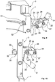
- Figure 9 shows a linkage 5 in the unlocking position in which the half-mould (not shown) can be extracted from the half-mould holder 3 by means of a rotary motion about the longitudinal axis thereof in the opposite direction to the rotary motion in the insertion step.
- the front end 32 of bolt 29 is in fact within through-hole 31 and does not interfere with the half-mould (not shown).
- Figure 10 shows a linkage 5 in the locking position in which the half-mould (not shown) and half-mould holder 3 are integrally locked to each other. Indeed, front end 32 of bolt 29 emerges from through-hole 31 and is inserted into seat 20 of half-mould 2, as shown in Figures 7a and 8a .
- seat 20 is provided by means of milling, defining a localized seat in the external surface of half-mould 2.
- a variant provides for a semi-annular groove 50 in the external surface of half-mould 2, made in a lathe, into which a semi-annular plug 51 is inserted which, once fixed by means of screws 52 and/or pin 53 to half-mould 2, defines a guide tooth for the substantially wedge-shaped end 32 of bolt 29.
- Said alternative solution has the advantage that, in the event of wear to the guide tooth, it is possible to simply replace only the semi-annular plug rather than the entire half-mould.
- the bolt in the shape of fourth longitudinal pin 29, in the example in Figures 9 and 10 passes through the third transversal pin 28 by means of an appropriate hole obtained thereon, and is integrally fixed to said third transversal pin 28 by means of a nut 30 screwed onto the threaded end of pin 29 protruding from said third pin 28.
- first lever 22 In passing from the unlocking position ( Figure 9 ) to the locking position ( Figure 10 ), the first lever 22 is moved, e.g. manually, acting with a first force on a grip 21 which may be provided thereon.
- the rotation movement of first lever 22 sets the pair of second levers 25 in motion about the second pin 26 and, in turn, sets in motion the third transversal pin 28 which will push with a second force, greater than the first force, fourth longitudinal pin 29 towards the inside of the mould until it is inserted into the respective seat 20 of half-mould 2.
- the longitudinal pin 29 reaches the locking position, the control lever 22 remains locked due to the aforementioned linkage reaching the toggle configuration.
- the bolt may be a presser member, such as a pressure screw.
- a presser member such as a pressure screw.
- the locking element 29' actuatable by the force multiplier mechanism, moves substantially along a circumference arc, preferably on a substantially horizontal plane.
- two quick coupling devices are provided for each half-mould holder 3.
- the option of providing at least three quick coupling devices for each half-mould holder 3 is contemplated.
- a single quick coupling device may also be provided for each half-mould holder 3.
- Locking element 29' of the quick coupling device actuated by the force multiplier mechanism, moves along a circumference arc until it interacts with a corresponding flat surface formed in part by a portion of the half-mould and in part by a portion of the half-mould holder.
- locking element 29' is inserted into a recess 31', provided in the contact wall 7 of half-mould holder 3, until it interacts with half-mould 2 whereby the respective half-mould and half-mould holder are locked to each other, determining the locking of the half-mould to the mould holder by friction.
- the locking may take place ( Fig.12 ) by means of providing a seat or recess 20' in a portion of the contact wall 7' of half-mould 2, said seat or recess 20' having a suitable shape to accommodate at least part of one end of said locking element in the shape of a pin or wedge or push rod, for example.
- a corresponding seat may be provided in the contact wall of the half-moulds, said seat having a suitable shape to ensure locking without clearances.
- Figure 11a shows a linkage 5' in the unlocking position in which the half-mould 2 can be extracted from the half-mould holder 3 by means of a rotary motion about the longitudinal axis thereof in the opposite direction to the rotary motion in the insertion step.
- Figure 11b shows a linkage 5' in the locking position in which half-mould 2 and half-mould holder 3 are integrally locked to each other. Indeed, the front end of locking element 29' is inserted into a recess 20' of half-mould 2 and into the recess 31' of half-mould holder 3.
- An alternative variant (not shown) of this second embodiment provides that the locking element 29' of the quick coupling device, actuated by the force multiplier mechanism, moves along a circumference arc until it interacts with a corresponding flat surface provided exclusively on the half-mould.
- the locking element 29' enters into contact with a portion of flat surface of the contact wall 7' of half-mould 2, determining the locking of the half-mould to the mould holder by friction, or it is inserted into a seat or recess, provided in the contact wall 7' of half-mould 2, whereby the respective half-mould and half-mould holder are locked to each other, determining the locking of the half-mould to the half-mould holder by interlocking.
- the seat has a suitable shape to accommodate an end of said locking element in the shape of a pin or wedge or push rod, for example. For every force multiplier mechanism, and therefore for every locking element, a corresponding seat will be provided in the contact wall of the half-moulds, said seat having a suitable shape to guarantee locking without clearances.
- the locking element which is a retaining device, may also be, for example, a pin or wedge or push rod or a presser member, such as a pressure screw or another appropriate element.
- the locking element may be of various shapes and the cross-section thereof may be round, oval, quadrangular, triangular, for example.
- the possible seat or recess may have a form which at least partially corresponds to that of the cross-section of the locking element.
- the force multiplier mechanism comprises a horizontal locking system with hinged levers 5', (or horizontal toggle locking system), or simply linkage, of the arc movement type, i.e. configured so that the locking element moves on a horizontal plane along a circumference arc from the unlocking position to the locking position, or vice versa.
- the linkage 5' is the model 205-Standard by DESTACO (205-U - Horizontal Hold-Down Toggle Locking Clamp), which is available on the market.
- Said locking system is configured so that, when the operator exerts a first force on first control lever 22', said force is multiplied obtaining a second force, denominated locking force, which is much greater than said first force, in order to safely lock the half-mould 2 with the relative half-mould holder 3.
- first lever 22' In passing from the unlocking position ( Figure 14a ) to the locking position ( Figure 14b ) first lever 22' is moved manually, acting with a first force. The rotation movement of first lever 22' about first pin 23' sets second lever 25' in motion, which rotates about second pin 26'.
- First lever 22' and second lever 25' are hinged to each other and to the support structure 24', fixed to the sidewall 6 of half-mould holder 3, so as to obtain a second force, of greater intensity than the first force, so that the locking element 29' which moves through a circumference arc enters into contact with a portion of flat surface provided in the only contact wall 7' of half-mould 2 or provided in part on contact wall 7' of half-mould 2 and in part on contact wall 7 of half-mould holder 3. In this way, locking takes place by friction.
- a seat or recess 20' may also be provided, obtained on contact wall 7' or also on contact wall 7, in order to specially accommodate an end of locking element 29'. In this way, instead, locking takes place by interlocking.
- the two lateral half-elements 1' of the blow mould can be closed.
- an appropriate recess on the corresponding second lateral half-element (not shown) in order to accommodate the part of linkage 5' which, in the locking position ( Fig. 14b ), protrudes from the contact walls 7, 7' of half-mould holder and half-mould 2.
- the force multiplier mechanism of every quick coupling device may comprise, for example, horizontal locking systems with hinged levers of the arc movement type with control lever parallel or inclined with respect to the locking axis, or horizontal locking systems with hinged levers of the rectilinear movement type with control lever inclined with respect to the locking axis, or vertical locking systems with hinged levers of the type with horizontal or vertical control lever.
- the quick coupling system of the blow mould of the present invention may be applied to blow moulds both with vertical oscillation pin of the half-mould holders ("jackknife-type" mould) and with horizontal oscillation pin of the half-mould holders.
- blow moulds comprising two or more impressions of containers to be moulded.
Landscapes
- Engineering & Computer Science (AREA)
- Mechanical Engineering (AREA)
- Manufacturing & Machinery (AREA)
- Moulds For Moulding Plastics Or The Like (AREA)
- Casting Devices For Molds (AREA)
Description
- The present invention relates to a blow mould or stretch-blow mould of at least one preheated preform, made of thermoplastic material, for the production of containers; the mould being provided with a quick coupling system for fixing the half-impression of each lateral half-mould to the respective half-mould holder.
- Generally, the two lateral half-moulds of a blow mould, for the production of containers made of thermoplastic material, are removably fixed to the respective half-mould holders whereby said half-moulds may be replaced, without the need of having to replace the entire moulding device, in the event of damage or wear or, above all, in the event that it is necessary to produce containers of different shapes and/or sizes.
- In this known solution, each half-mould is extremely heavy, e.g. around 20 kg for a steel mould. The fixing means must be capable of supporting this weight and comprise many nut-screw joints and/or threaded joints. Moreover, each half-mould is provided with ducts for the circulation of one or more fluids for cooling and/or heating the walls of the half-impression obtained in the inner cavity of the half-mould. Said ducts are connected to fluid feed pipes with joints for connection to the half-mould. Therefore, replacing each half-mould also involves the disconnection and subsequent re-connection of the respective pipe joints.
- All these aspects cause extremely long replacement times of the two half-impressions in a blow mould, which may reach around 10 minutes per mould.
- A solution to this problem was obtained by means of the blow mould described in the document
EP0821641 . - This blow mould consists of two lateral half-moulds, each supported by a half-mould holder, the two half-mould holders being movable with respect to each other.
- The quick coupling device used in this solution, although lowering half-impression replacement times to 5 minutes, continues to not satisfy the needs of the current market, above all for modern blow moulding machines having a large number of moulds. Moreover, a further disadvantage is represented by the fact that it is always necessary to use external tools for the disassembly and assembly of said half-impressions. Indeed, even if so-called quick coupling devices are used, a predetermined number of screws has to be loosened in order to allow the half-mould locking tabs to be moved radially outwards, enabling the extraction thereof. Subsequently, said predetermined number of screws must be tightened again once the half-impression has been changed, in order to allowing locking of the half-mould by means of the aforementioned tabs moved radially towards the inside of the mould in corresponding flat seats, provided in the separation or contact surface of the half-mould. A quick coupling system of the known art having the features of the preamble of
claim 1 is disclosed inWO2011026980A1 . In this document a solution is proposed where the means, for fixing each mould half to the mould carrier, are mounted in such a way that they can move simultaneously between a fixing position and a release position and can be controlled as they move between these two positions when the mould carriers are in the closed position. - The need is therefore felt to provide a blow mould provided with a quick coupling system for the lateral half-impressions which allows the aforementioned drawbacks to be overcome.
- The primary object of the present invention is to provide a blow mould provided with a locking system to lock each half-mould to the respective half-mould holder, allowing simpler and quicker replacement of the lateral half-impressions of the mould.
- A further object of the invention is to provide a blow mould in which it is no longer necessary to use external tools to remove and replace said half-impressions, due to the presence of a force multiplier mechanism.
- The present invention, therefore, proposes to achieve the objects discussed above by providing a blow mould for plastic containers which, in accordance with
claim 1, comprises: - at least two half-moulds,
- at least two half-mould holders, each half-mould holder supporting one of said half-moulds, each half-mould holder and each half-mould defining respective complementary coupling surfaces between half-mould holder and half-mould,
- at least one quick coupling device to lock each half-mould to the respective half-mould holder,
- Advantageously, the blow mould of the invention provides that the half-impression of each lateral half-mould is fixed with respect to the corresponding half-mould holder by means of actuating at least one quick coupling device. Said quick coupling device may also be provided in the event that the mould provides for the presence of a mould bottom which is distinct (separate) from the two lateral half-moulds, called bottom plate or base plate in technical jargon and comprising the bottom impression of the container to be blown.
- Said at least one quick coupling device comprises a force multiplier mechanism, including at least one first lever, configured to multiply a first force applied, also simply manually, on said first lever in order to obtain a second force, denominated locking force, which is much greater than said first force, in order to safely lock the lateral half-mould with the relative half-mould holder.
- Said force multiplier mechanism is configured so as to actuate a respective locking element from an unlocking position, in which the half-mould or a part thereof can be extracted from the half-mould holder, to a locking position, in which half-mould and half-mould holder are integrally locked to each other, or vice versa. Advantageously the quick coupling device, together with all components thereof, is fixed to a wall of the half-mould holder and, in particular, the force multiplier mechanism remains cinematically fixed to the quick coupling device both in said unlocking position and in said locking position.
- The force multiplier mechanism can comprise, for example, a locking system with hinged levers or simply locking linkage. Said system includes a first control lever, firmly hinged to the respective half-mould holder. In particular, said lever can be firmly hinged to a support element integrally fixed to a sidewall of the half-mould holder. This advantageously allows the operator to not have to use further tools, e.g. an external lever which is not part of the quick coupling device integral with the mould, for the disassembly and assembly of the lateral half-moulds and the respective half-impressions. Indeed, the disassembly or assembly operation which provides for the use of external levers requires more time inasmuch as the operator must equip himself with said lever and insert it into the quick coupling device, the latter operation not being immune from further losses of time in the event that the insertion is not achieved at the first attempt or the lever falls to the ground and must be retrieved and inserted again. The fact of providing the entire quick coupling device fixed to the respective half-mould holder allows the operations of replacing the lateral half-impressions of the mould to be further accelerated.
- In a first advantageous embodiment, both the force multiplier mechanism and the respective locking element are positioned so as to not interfere at all with the contact walls of the respective half-mould holder and half-mould. By contact walls of a half-mould holder and relative lateral half-mould it is meant those internal walls or edges which, once the blow mould is closed, adhere to the corresponding internal walls or edges of the opposing half-mould holder and relative half-mould, defining a plane of contact between the two lateral half-elements of the mould, leaving as a non-contact zone between said two half-elements at least the empty zone corresponding to the internal volume of the container to be moulded.
- In a second advantageous embodiment, instead, both the force multiplier mechanism and the respective locking element are positioned so as to interfere with the contact walls of the respective half-mould holder and half-mould or exclusively with the contact wall of the respective half-mould.
- The blow mould of the invention allows the replacement times of the two lateral half-impressions of the mould to be reduced to around 1 minute, thus reducing the replacement time in a blowing machine with several blowing stations.
- The dependent claims describe preferred embodiments of the invention.
- Further features and advantages of the invention will become clearer in light of the detailed description of preferred but not exclusive embodiments of a blow mould, shown by way of non-limiting example with the aid of the attached drawings in which:
-
Figure 1 represents a perspective view of a first embodiment of the blow mould according to the invention; -
Figure 2 represents a perspective view of a part of the blow mould inFigure 1 ; -
Figure 3 represents a view of the internal part of a half-mould holder of the blow mould inFigure 1 ; -
Figure 4 represents a view of the external part of a half-mould holder of the blow mould inFigure 1 ; -
Figure 4a and 4b represent side views of the external part of the half-mould holder inFigure 4 ; -
Figure 5 represents a top view of the half-mould holder inFigure 4 ; -
Figure 6 represents an enlargement of part of the view inFigure 4b ; -
Figure 7 represents a section view of half-mould holder and half-mould; -
Figure 7a represents an enlargement of part of the view inFigure 7 ; -
Figure 7b represents a frontal view of half-mould holder and half-mould; -
Figure 8a represents a section view of half-mould holder and half-mould inFigure 7b along the plane B-B; -
Figure 8b represents a section view according to the plane E-E of the half-mould holder and the half-mould inFigure 7 ; -
Figure 9 represents a perspective view of a first component of the half-mould holder inFigure 3 ; -
Figure 10 represents a perspective view of a second component of the half-mould holder inFigure 3 ; -
Figures 11a and11b represent perspective views of parts of a second embodiment of the blow mould; -
Figure 12 represents a frontal view of the internal part of the blow mould inFig. 11b ; -
Figure 13 represents a side view of the external part of the half-mould holder visible inFigure 12 ; -
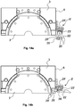
Figures 14a and 14b represent top views of half-mould holder and relative half-mould visible inFigure 12 . - Equal reference numbers in the figures identify the same elements or components.
- With reference to the Figures, a blow mould is represented, globally indicated with the
reference number 1, for the production of containers, in particular bottles, made of thermoplastic material such as PET, PEN or other suitable material, or mixtures thereof, by means of blow moulding or stretch-blow moulding of preheated preforms. -
Blow mould 1 comprises two lateral half-elements 1', each lateral half-element 1' comprising a lateral half-mould 2 supported by a half-mould holder 3. The term half-mould comprises both a lateral half-mould made as a single piece, and a lateral half-mould comprising several pieces placed on top of each other. In the latter case it is possible, by changing just one piece of the half-mould, to vary the height of the containers to be moulded or obtain containers which are slightly different in shape. -
Blow mould 1, object of the present invention, comprises two lateral half-moulds 2, each supported by a respective half-mould holder 3, the two half-mould holders 3 being movable with respect to each other. The adjective "lateral" in this description, associated with the terms half-element, half-mould, half-mould holder and half-impression, relates to a side or lateral portion of the container to be blown with respect to the longitudinal axis of the container itself. The definition of lateral half-mould in this description is also maintained in the event that the mould is provided therein with a further element which defines the bottom of the mould, called bottom plate in technical jargon, which is distinct from the two lateral half-moulds. The bottom of the mould comprises the bottom impression of the container to be blown. Said bottom impression of the container and the lateral half-impressions, provided in the half-moulds, define the impression or global figure of the container to be blown in the mould. - Each half-
mould holder 3 is provided with (Figures 3 to 5 ): - an external surface thereof comprising a first
lateral wall 6, a secondlateral wall 12 substantially parallel to saidfirst wall 6, and a thirdlateral wall 13 connecting saidfirst wall 6 to saidsecond wall 12; - and an internal surface thereof comprising the
contact walls mould holder 3 and aninternal wall 14, which is substantially semi-cylindrical, connecting saidcontact walls - Each lateral half-
mould 2 comprises a substantially semi-cylindrical external surface thereof (not shown) and an internal surface thereof comprising (Figure 2 ) thecontact walls 7', 8' of half-mould 2 and an internal cavity defining the lateral half-impression 4 of the container to be moulded. - The
internal wall 14 of half-mould holder 3 and the external surface of half-mould 2 are of substantially complementary shape so as to enter in contact at least partially with each other for purposes of heat conduction and mechanical connection. Therefore, saidinternal wall 14 of half-mould holder 3 and said external surface of half-mould 2 define respective coupling surfaces between half-mould holder and half-mould, which are at least partially complementary to each other. - The ducts for the circulation of cooling and/or heating fluids for the half-impressions are generally provided in the half-
mould holders 3. This allows the disconnection and subsequent re-connection of the respective pipe joints, to which said ducts are connected, to be avoided, when it is necessary to carry out the replacement of the half-moulds. - However, in alternative variants, the ducts for the circulation of cooling and/or heating fluids for the half-impressions may also or exclusively be provided in the half-
moulds 2. - In the event that the blow mould, object of the present invention, is also provided therein with a mould bottom, called bottom plate in technical jargon, which is distinct from the two lateral half-
moulds 2, the ducts for the circulation of cooling and/or heating fluids may also be provided in said bottom plate. - Advantageously, axial mutual positioning means for half-
mould 2 and half-mould holder 3 are provided. In particular, at least onesemi-annular protuberance 11 can be provided on theinternal wall 14 of half-mould holder 3 to which at least one respective semi-annular recess corresponds in the external surface of half-mould 2, or vice versa, in order to facilitate the insertion of the half-mould into the half-mould holder by means of a rotary motion of said half-mould about a longitudinal axis thereof. In a variant (not shown), two semi-annular protuberances and two respective semi-annular recesses may be provided. - On the opposite side to where the insertion of the half-mould into the half-mould holder begins, at least one
stop element 10 is further provided in order to correctly align thecontact wall 8' of half-mould 2 with thecontact wall 8 of half-mould holder 3. In the example inFigure 3 , there is provided aplate 9, fixed to thecontact wall 8 of half-mould holder 3, from which three stopelements 10 protrude internally. Each lateral half-mould 2 is detachably locked to the respective half-mould holder 3 by means of at least one quick coupling device, described in detail below, fixed together with all components thereof to said half-mould holder 3. - In the event that the half-mould holders are rotationally hinged to each other by means of a vertical oscillation pin, to form a "jackknife" or "book-type" mould, said at least one
stop element 10 is provided on each half-mould holder on the side of the oscillation pin of the half-mould holders, while at least one quick coupling device is arranged on the opposite side. - Advantageously, the quick coupling device comprises a locking element and a force multiplier mechanism, incorporating a first lever, in order to multiply a first force applicable on said first lever and obtain a second force, greater than the first force, in order to lock the respective half-mould and half-mould holder. Said force multiplier mechanism is configured so as to move said locking element until it interacts with half-
mould 2 whereby the respective half-mould and half-mould holder are locked to each other in a position in which the respective complementary coupling surfaces are coupled to each other. - Said force multiplier mechanism is configured so as to actuate the respective locking element from an unlocking position, in which half-
mould 2 can be extracted from half-mould holder 3, to a locking position, in which half-mould 2 and half-mould holder 3 are integrally locked to each other, or vice versa. - The quick coupling device is integral with first
lateral wall 6 of the external surface of half-mould holder 3 and is fixed to said firstlateral wall 6 at a predetermined distance, other than zero, from thecorresponding contact wall 7 of the same half-mould holder 3, adjacent to said first wall 6 (Figures 5 and14 ). - In a first preferred embodiment, the locking element is a bolt or
slider 29, actuatable by the force multiplier mechanism, which moves along a locking axis X, visible in the example shown inFigure 5 , parallel and suitably spaced from the contact plane on which thecontact walls contact walls Figures 1 to 10 , two quick coupling devices are provided for each half-mould holder 3. However, the option to provide only one quick coupling device for each half-mould holder 3 is not excluded. - The bolt may be of various shapes and the cross-section thereof may be round, oval, quadrangular, triangular, for example.
- In a similar way to the bolt of a lock which, emerging from the door leaf upon turning of the key, interacts with the other door leaf or with the doorpost thus stopping the door, the bolt or
slider 29 of the quick coupling device, actuated by the force multiplier mechanism, emerges from half-mould holder 3 through an opening, preferably but not necessarily a through-hole 31, provided in the thickness of the half-mould holder 3, in order to interact with the coupling surface of the respective half-mould 2 whereby the respective half-mould and half-mould holder are locked to each other. - The bolt, which is a retaining device, may be constituted, for example, by a pin or wedge or push rod or a presser member, such as a pressure screw or another appropriate element which can pass through the
first wall 6 by means of a respective opening, obtained therein, until arriving in the locking position in which it interacts with a portion of the external surface of the half-mould 2, determining the locking of the half-mould to the mould holder by interlocking or by friction. According to a first advantageous variant, the locking takes place by means of providing a seat or recess 20 (Figure 8a ) in a portion of the coupling surface of half-mould 2, said seat orrecess 20 having a suitable shape to accommodate an end of said bolt in the shape of a pin or wedge or push rod, for example. For every force multiplier mechanism, and therefore for every bolt, a corresponding seat will be provided in the external coupling surface of the half-moulds, said seat having a suitable shape to guarantee locking without clearances. - The locking may also take place, in a second advantageous variant, without providing any seat or recess in the external coupling surface of the half-
mould 2, having a shape specially designed to accommodate an end of said bolt. Indeed, when using a presser member, such as a pressure screw, as a bolt, this special seat is not necessary. Indeed, the multiplying of the force applied on thefirst lever 22 enables a greater force to be obtained which will be exerted by the presser member on a portion of the external coupling surface of the half-mould, ensuring the locking of the half-mould by friction. - By way of example, a variant of the quick coupling device, suitable for said first preferred embodiment, is shown in the
Figures 7a to 10 . In this case, the force multiplier mechanism comprises a horizontal locking system with hingedlevers 5, configured so that the bolt is made to move in a horizontal direction from the unlocking position to the locking position, or vice versa. - Said horizontal locking system with hinged levers or
linkage 5 in turn comprises: - a
support structure 24 fixed to thelateral wall 6 of half-mould holder 3; - a
first control lever 22, hinged at a first end thereof onfirst pins 23 protruding from two opposite sides of saidsupport structure 24; - a pair of
second levers 25, arranged parallel to each other and hinged at a first end thereof on respectivesecond pins 26 integral with saidfirst lever 22 at the first end thereof, and integrally hinged at a second end thereof on a thirdtransversal pin 28 which connects said second levers 25 to each other; - a bolt in the shape of a fourth
longitudinal pin 29, integrally fixed to said thirdtransversal pin 28 and positioned longitudinally at a through-hole 31 provided infirst wall 6 of mould-holder 3. - In the external surface of half-
mould 2, a seat orrecess 20 is provided so as to accommodate an end of said fourthlongitudinal pin 29 when it reaches the locking position. -
Figure 9 shows alinkage 5 in the unlocking position in which the half-mould (not shown) can be extracted from the half-mould holder 3 by means of a rotary motion about the longitudinal axis thereof in the opposite direction to the rotary motion in the insertion step. Thefront end 32 ofbolt 29 is in fact within through-hole 31 and does not interfere with the half-mould (not shown). -
Figure 10 shows alinkage 5 in the locking position in which the half-mould (not shown) and half-mould holder 3 are integrally locked to each other. Indeed,front end 32 ofbolt 29 emerges from through-hole 31 and is inserted intoseat 20 of half-mould 2, as shown inFigures 7a and8a . - With reference to the section in
Figure 8a ,seat 20 is provided by means of milling, defining a localized seat in the external surface of half-mould 2. - With reference to the section in
Figure 8b , a variant provides for asemi-annular groove 50 in the external surface of half-mould 2, made in a lathe, into which asemi-annular plug 51 is inserted which, once fixed by means ofscrews 52 and/or pin 53 to half-mould 2, defines a guide tooth for the substantially wedge-shapedend 32 ofbolt 29. Said alternative solution has the advantage that, in the event of wear to the guide tooth, it is possible to simply replace only the semi-annular plug rather than the entire half-mould. - The bolt in the shape of fourth
longitudinal pin 29, in the example inFigures 9 and 10 , passes through the thirdtransversal pin 28 by means of an appropriate hole obtained thereon, and is integrally fixed to said thirdtransversal pin 28 by means of anut 30 screwed onto the threaded end ofpin 29 protruding from saidthird pin 28. - In passing from the unlocking position (
Figure 9 ) to the locking position (Figure 10 ), thefirst lever 22 is moved, e.g. manually, acting with a first force on agrip 21 which may be provided thereon. The rotation movement offirst lever 22 sets the pair ofsecond levers 25 in motion about thesecond pin 26 and, in turn, sets in motion the thirdtransversal pin 28 which will push with a second force, greater than the first force, fourthlongitudinal pin 29 towards the inside of the mould until it is inserted into therespective seat 20 of half-mould 2. Once thelongitudinal pin 29 reaches the locking position, thecontrol lever 22 remains locked due to the aforementioned linkage reaching the toggle configuration. - In order to unlock the half-mould holder/half-mould group it will be necessary to again apply a force, in the opposite direction to said first force, on the
control lever 22. - In alternative to the fourth
longitudinal pin 29, the bolt may be a presser member, such as a pressure screw. In this case, locking between half-mould and half-mould holder takes place by friction between the bolt, which passes through half-mould holder 3, and the coupling surface of half-mould 2, thus without the necessity to provide a special seat or recess to accommodate the end of the bolt. - In a second preferred embodiment, shown in the Figures from 11 to 14, the locking element 29', actuatable by the force multiplier mechanism, moves substantially along a circumference arc, preferably on a substantially horizontal plane.
- In the example in the Figures from 11 to 13, two quick coupling devices are provided for each half-
mould holder 3. The option of providing at least three quick coupling devices for each half-mould holder 3 is contemplated. A single quick coupling device may also be provided for each half-mould holder 3. - Locking element 29' of the quick coupling device, actuated by the force multiplier mechanism, moves along a circumference arc until it interacts with a corresponding flat surface formed in part by a portion of the half-mould and in part by a portion of the half-mould holder.
- In particular, locking element 29' is inserted into a recess 31', provided in the
contact wall 7 of half-mould holder 3, until it interacts with half-mould 2 whereby the respective half-mould and half-mould holder are locked to each other, determining the locking of the half-mould to the mould holder by friction. - The locking may take place (
Fig.12 ) by means of providing a seat or recess 20' in a portion of the contact wall 7' of half-mould 2, said seat or recess 20' having a suitable shape to accommodate at least part of one end of said locking element in the shape of a pin or wedge or push rod, for example. For every force multiplier mechanism, and therefore for every locking element, a corresponding seat may be provided in the contact wall of the half-moulds, said seat having a suitable shape to ensure locking without clearances. -
Figure 11a shows a linkage 5' in the unlocking position in which the half-mould 2 can be extracted from the half-mould holder 3 by means of a rotary motion about the longitudinal axis thereof in the opposite direction to the rotary motion in the insertion step. -
Figure 11b shows a linkage 5' in the locking position in which half-mould 2 and half-mould holder 3 are integrally locked to each other. Indeed, the front end of locking element 29' is inserted into a recess 20' of half-mould 2 and into the recess 31' of half-mould holder 3. - An alternative variant (not shown) of this second embodiment provides that the locking element 29' of the quick coupling device, actuated by the force multiplier mechanism, moves along a circumference arc until it interacts with a corresponding flat surface provided exclusively on the half-mould.
- In particular, the locking element 29' enters into contact with a portion of flat surface of the contact wall 7' of half-
mould 2, determining the locking of the half-mould to the mould holder by friction, or it is inserted into a seat or recess, provided in the contact wall 7' of half-mould 2, whereby the respective half-mould and half-mould holder are locked to each other, determining the locking of the half-mould to the half-mould holder by interlocking. The seat has a suitable shape to accommodate an end of said locking element in the shape of a pin or wedge or push rod, for example. For every force multiplier mechanism, and therefore for every locking element, a corresponding seat will be provided in the contact wall of the half-moulds, said seat having a suitable shape to guarantee locking without clearances. - In this second embodiment, the locking element, which is a retaining device, may also be, for example, a pin or wedge or push rod or a presser member, such as a pressure screw or another appropriate element. The locking element may be of various shapes and the cross-section thereof may be round, oval, quadrangular, triangular, for example. The possible seat or recess may have a form which at least partially corresponds to that of the cross-section of the locking element.
- By way of example, an embodiment of the quick coupling device, suitable for said second preferred embodiment, is shown in the Figures from 11 to 14. In this case, the force multiplier mechanism comprises a horizontal locking system with hinged levers 5', (or horizontal toggle locking system), or simply linkage, of the arc movement type, i.e. configured so that the locking element moves on a horizontal plane along a circumference arc from the unlocking position to the locking position, or vice versa.
- In the example shown in the Figures from 11 to 14, the linkage 5' is the model 205-Standard by DESTACO (205-U - Horizontal Hold-Down Toggle Locking Clamp), which is available on the market.
- Said locking system is configured so that, when the operator exerts a first force on first control lever 22', said force is multiplied obtaining a second force, denominated locking force, which is much greater than said first force, in order to safely lock the half-
mould 2 with the relative half-mould holder 3. - In passing from the unlocking position (
Figure 14a ) to the locking position (Figure 14b ) first lever 22' is moved manually, acting with a first force. The rotation movement of first lever 22' about first pin 23' sets second lever 25' in motion, which rotates about second pin 26'. First lever 22' and second lever 25' are hinged to each other and to the support structure 24', fixed to thesidewall 6 of half-mould holder 3, so as to obtain a second force, of greater intensity than the first force, so that the locking element 29' which moves through a circumference arc enters into contact with a portion of flat surface provided in the only contact wall 7' of half-mould 2 or provided in part on contact wall 7' of half-mould 2 and in part oncontact wall 7 of half-mould holder 3. In this way, locking takes place by friction. - A seat or recess 20' may also be provided, obtained on contact wall 7' or also on
contact wall 7, in order to specially accommodate an end of locking element 29'. In this way, instead, locking takes place by interlocking. - In the locking step (
Figure 14b ), once the locking element 29' reaches the locking position, the first control lever 22' remains locked due to the aforementioned linkage reaching the toggle configuration. - In order to unlock the half-mould holder/half-mould group it will be necessary to again apply a force, in the opposite direction to the first force, on control lever 22'. In alternative, any other horizontal locking system with hinged levers which has a similar method of operation may be used, including ones which are commercially available.
- With this second embodiment, once the locking position has been reached by the quick coupling device 5', the two lateral half-elements 1' of the blow mould can be closed. Advantageously at each quick coupling device 5' on a first lateral half-element 1', there is provided an appropriate recess on the corresponding second lateral half-element (not shown) in order to accommodate the part of linkage 5' which, in the locking position (
Fig. 14b ), protrudes from thecontact walls 7, 7' of half-mould holder and half-mould 2. - More generally, the force multiplier mechanism of every quick coupling device may comprise, for example, horizontal locking systems with hinged levers of the arc movement type with control lever parallel or inclined with respect to the locking axis, or horizontal locking systems with hinged levers of the rectilinear movement type with control lever inclined with respect to the locking axis, or vertical locking systems with hinged levers of the type with horizontal or vertical control lever. Advantageously, the quick coupling system of the blow mould of the present invention may be applied to blow moulds both with vertical oscillation pin of the half-mould holders ("jackknife-type" mould) and with horizontal oscillation pin of the half-mould holders.
- It can further be applied to blow moulds comprising two or more impressions of containers to be moulded.
Claims (6)
- A blow mould (1) for plastic containers comprising- at least two half-moulds (2),- at least two half-mould holders (3), each half-mould holder (3) supporting one of said half-moulds (2), each half-mould holder (3) and each half-mould (2) defining respective complementary coupling surfaces between half-mould holder and half-mould,- at least one quick coupling device (5) to lock each half-mould (2) to the respective half-mould holder (3),wherein said at least one quick coupling device (5) is fixed to the respective half-mould holder (3) characterised in that it comprises only one locking element and a force multiplier mechanism,
the force multiplier mechanism comprises a locking system with hinged levers (22, 25), configured so as to move the locking element (29) along a rectilinear locking axis (X),
a first one (22) of said hinged levers is firmly hinged to the respective half-mould holder (3),(i) said locking element is a bolt (29) that can move, by actuating said force multiplier mechanism, from an unlocking position to a locking position by emerging from the half-mould holder (3) through a through hole (31) provided in the thickness of the half-mould holder (3), to interact with the coupling surface of the respective half-mould (2), whereby half-mould (2) and respective half-mould holder (3) are locked to each other in a position in which the respective complementary coupling surfaces are coupled to each other, and wherein(ii) said force multiplier mechanism remains kinematically fixed to the quick coupling device both in said unlocking position and in said locking position. - A blow mould according to claim 1, wherein said lever (22) is hinged to a support structure (24) integrally fixed to a sidewall (6) of the half-mould holder (3).
- A blow mould according to claim 2, wherein said rectilinear locking axis (X) is substantially parallel and suitably spaced from a plane on which contact walls (7, 8) lie, defining a contact zone of half-mould holder (3) and half-mould (2) with the other half-mould holder and the other half-mould of the blow mould, respectively, when the mould is closed.
- A blow mould according to claim 3, wherein said bolt (29) is a presser member adapted to exert a pressure on the complementary coupling surface of the half-mould (2), whereby respective half-mould and half-mould holder are locked by friction to each other.
- A blow mould according to claim 3, wherein there is provided a seat (20), obtained on the complementary coupling surface of the respective half-mould (2), whereby one end (32) of said bolt (29) can be inserted into said seat (20), thus blocking respective half-mould and half-mould holder by interlocking.
- A blow mould according to any one of the preceding claims, wherein two or more quick coupling devices are provided to lock each half-mould (2) to the respective half-mould holder (3).
Priority Applications (1)
| Application Number | Priority Date | Filing Date | Title |
|---|---|---|---|
| EP20156061.2A EP3677404A1 (en) | 2011-03-30 | 2012-03-30 | Blow mould |
Applications Claiming Priority (2)
| Application Number | Priority Date | Filing Date | Title |
|---|---|---|---|
| IT000165A ITRM20110165A1 (en) | 2011-03-30 | 2011-03-30 | BLOWING MOLD |
| PCT/EP2012/055791 WO2012131039A1 (en) | 2011-03-30 | 2012-03-30 | Blow mould |
Related Child Applications (2)
| Application Number | Title | Priority Date | Filing Date |
|---|---|---|---|
| EP20156061.2A Division-Into EP3677404A1 (en) | 2011-03-30 | 2012-03-30 | Blow mould |
| EP20156061.2A Division EP3677404A1 (en) | 2011-03-30 | 2012-03-30 | Blow mould |
Publications (2)
| Publication Number | Publication Date |
|---|---|
| EP2691225A1 EP2691225A1 (en) | 2014-02-05 |
| EP2691225B1 true EP2691225B1 (en) | 2020-05-27 |
Family
ID=43977393
Family Applications (2)
| Application Number | Title | Priority Date | Filing Date |
|---|---|---|---|
| EP20156061.2A Withdrawn EP3677404A1 (en) | 2011-03-30 | 2012-03-30 | Blow mould |
| EP12717229.4A Active EP2691225B1 (en) | 2011-03-30 | 2012-03-30 | Blow mould |
Family Applications Before (1)
| Application Number | Title | Priority Date | Filing Date |
|---|---|---|---|
| EP20156061.2A Withdrawn EP3677404A1 (en) | 2011-03-30 | 2012-03-30 | Blow mould |
Country Status (7)
| Country | Link |
|---|---|
| US (1) | US9186841B2 (en) |
| EP (2) | EP3677404A1 (en) |
| CN (1) | CN103459123B (en) |
| ES (1) | ES2812565T3 (en) |
| IT (1) | ITRM20110165A1 (en) |
| WO (1) | WO2012131039A1 (en) |
| ZA (1) | ZA201308053B (en) |
Families Citing this family (17)
| Publication number | Priority date | Publication date | Assignee | Title |
|---|---|---|---|---|
| DE102013106481A1 (en) | 2013-06-21 | 2014-12-24 | Krones Ag | Retaining ring for a blow mold for locking and fixing a plastic preform |
| DE102014101853A1 (en) * | 2014-02-13 | 2015-08-13 | Krones Ag | Blow molding machine with centering of the blow molding base |
| DE102014105762A1 (en) * | 2014-04-24 | 2015-11-12 | Krones Ag | Blow molding machine with automatically operable ground coupling |
| FR3038541B1 (en) | 2015-07-08 | 2017-07-21 | Sidel Participations | MOLDING DEVICE FOR A MACHINE FOR MANUFACTURING THERMOPLASTIC CONTAINERS |
| CN105058749B (en) * | 2015-07-31 | 2017-05-03 | 江苏新美星包装机械股份有限公司 | Connecting structure between mold and mold base in bottle blowing machine |
| US9688012B2 (en) * | 2015-10-05 | 2017-06-27 | Milacron Llc | Blow mold assembly |
| US10052810B2 (en) | 2015-10-05 | 2018-08-21 | Milacron Llc | Blow mold assembly |
| ITUB20160870A1 (en) * | 2016-02-19 | 2017-08-19 | Sipa Progettazione Automaz | BLOWING MOLD |
| FR3053906B1 (en) | 2016-12-12 | 2018-08-17 | Sidel Participations | MOLDING DEVICE FOR IMPLEMENTING HOT MOLDING AND COLD MOLDING PROCESSES |
| CN107214989A (en) * | 2017-06-29 | 2017-09-29 | 任青礼 | A kind of base of the leather shoes making with anti-skid structure |
| CN107234754A (en) * | 2017-06-29 | 2017-10-10 | 任青礼 | A kind of base of the leather shoes making of convenient use |
| CN110406077B (en) * | 2019-07-17 | 2023-11-17 | 江苏新美星包装机械股份有限公司 | But mode locking device of quick replacement bottle blowing machine mould |
| CN111483131B (en) * | 2020-04-25 | 2021-11-23 | 义乌市叶之茂食品有限公司 | Plastic bottle processing mold |
| CN114434692B (en) * | 2020-11-05 | 2025-02-07 | 张再顺 | Quick mold change device for molding machine |
| CN113085145B (en) * | 2021-04-13 | 2022-05-06 | 沧州市永高农牧机械科技有限公司 | Blanking three-way blow molding die |
| CN114131996B (en) * | 2021-11-12 | 2023-12-12 | 四川航天川南火工技术有限公司 | Small-size left and right half mould compound locking mechanism |
| CN116587577A (en) * | 2023-07-04 | 2023-08-15 | 广州达意隆包装机械股份有限公司 | Handle mounting position forming mechanism and post handle bottle blowing machine |
Family Cites Families (12)
| Publication number | Priority date | Publication date | Assignee | Title |
|---|---|---|---|---|
| US2984176A (en) * | 1957-05-15 | 1961-05-16 | Us Industries Inc | Die clamp |
| FR2733176B1 (en) | 1995-04-19 | 1997-06-27 | Sidel Sa | DEVICE FOR MANUFACTURING CONTAINERS IN THERMOPLASTIC MATERIAL BY BLOWING OR STRETCH-BLOWING |
| US7335007B2 (en) * | 2005-04-18 | 2008-02-26 | Graham Packaging Company, L.P. | Quick change mold |
| DE102005035233A1 (en) * | 2005-07-25 | 2007-04-12 | Sig Technology Ag | Device for holding blow mold segments |
| CN2860804Y (en) * | 2005-12-01 | 2007-01-24 | 铨宝工业股份有限公司 | Clamping structure of rotary mold base |
| CN2936691Y (en) * | 2006-07-11 | 2007-08-22 | 广州达意隆包装机械股份有限公司 | Mould locking mechanism for bottle blowing machine |
| CN201325179Y (en) * | 2008-12-25 | 2009-10-14 | 解冬正 | Die opening and locking mechanism of bottle blowing machine |
| DE102009050637B4 (en) * | 2009-05-06 | 2019-06-19 | Krones Aktiengesellschaft | blow mold |
| MX2012002242A (en) * | 2009-09-07 | 2012-04-11 | Sidel Participations | METHOD FOR CHANGING A MOLD. |
| FR2949706A1 (en) * | 2009-09-07 | 2011-03-11 | Sidel Participations | MOLDING DEVICE EQUIPPED WITH FIXED CONTROL MEANS WITH TIGHTENING OF A HALF-MOLD BY SLIDING FASTENING PENES |
| DE102010033803A1 (en) * | 2010-08-09 | 2012-02-09 | Krones Aktiengesellschaft | blow mold |
| ITRM20110126A1 (en) * | 2011-03-16 | 2012-09-17 | Sipa Progettazione Automaz | BLOWING MOLD |
-
2011
- 2011-03-30 IT IT000165A patent/ITRM20110165A1/en unknown
-
2012
- 2012-03-30 WO PCT/EP2012/055791 patent/WO2012131039A1/en not_active Ceased
- 2012-03-30 ES ES12717229T patent/ES2812565T3/en active Active
- 2012-03-30 EP EP20156061.2A patent/EP3677404A1/en not_active Withdrawn
- 2012-03-30 CN CN201280016348.9A patent/CN103459123B/en active Active
- 2012-03-30 EP EP12717229.4A patent/EP2691225B1/en active Active
- 2012-03-30 US US14/008,135 patent/US9186841B2/en active Active
-
2013
- 2013-10-29 ZA ZA2013/08053A patent/ZA201308053B/en unknown
Non-Patent Citations (1)
| Title |
|---|
| None * |
Also Published As
| Publication number | Publication date |
|---|---|
| CN103459123A (en) | 2013-12-18 |
| ITRM20110165A1 (en) | 2012-10-01 |
| US20140017353A1 (en) | 2014-01-16 |
| ZA201308053B (en) | 2014-08-27 |
| EP2691225A1 (en) | 2014-02-05 |
| EP3677404A1 (en) | 2020-07-08 |
| WO2012131039A1 (en) | 2012-10-04 |
| CN103459123B (en) | 2015-11-25 |
| US9186841B2 (en) | 2015-11-17 |
| ES2812565T3 (en) | 2021-03-17 |
Similar Documents
| Publication | Publication Date | Title |
|---|---|---|
| US9186841B2 (en) | Blow mould | |
| US8974211B2 (en) | System for aiding in the replacement of a mould of a moulding unit of a machine for manufacturing containers | |
| AU707275B2 (en) | Device for manufacturing containers made of a thermoplastic by blow molding or stretch-blow molding | |
| US7037099B2 (en) | Device for blow-molding containers | |
| EP2418068B1 (en) | Quick-change molding system for injection molding | |
| US8408893B2 (en) | Rapid changeover mechanism for bottom portions | |
| CN102481720A (en) | Method for changing a mould | |
| US8770961B2 (en) | Molding device provided with a controlled means for clampingly attaching a half-mold by means of slidable attachment bolts | |
| EP3416807B1 (en) | Blow mould | |
| US8794953B2 (en) | Blow-molding device provided with means for attaching, by suction, a half-mold to a back wall of a corresponding recess of a mold carrier | |
| US8333581B2 (en) | Molding unit attachment system and molding unit comprising such a system | |
| RU2424902C1 (en) | Compensating rod for casting system and casting system with said compensating rod | |
| CN102009442A (en) | Machine for the manufacture of containers comprising a module for controlling devices of a moulding unit so as to effect a change of mould | |
| US20150343696A1 (en) | Blow-moulding device with preloadable attachment for blow moulds | |
| US7335007B2 (en) | Quick change mold | |
| CN103298598A (en) | Especially multi-part blow molds for the manufacture of plastic bottles | |
| EP2295224B1 (en) | An apparatus and a method for making plastic containers by blow-moulding parisons | |
| WO2001047683A1 (en) | Injection mold key lock | |
| KR20260059373A (en) | Injection mold |
Legal Events
| Date | Code | Title | Description |
|---|---|---|---|
| PUAI | Public reference made under article 153(3) epc to a published international application that has entered the european phase |
Free format text: ORIGINAL CODE: 0009012 |
|
| 17P | Request for examination filed |
Effective date: 20131029 |
|
| AK | Designated contracting states |
Kind code of ref document: A1 Designated state(s): AL AT BE BG CH CY CZ DE DK EE ES FI FR GB GR HR HU IE IS IT LI LT LU LV MC MK MT NL NO PL PT RO RS SE SI SK SM TR |
|
| DAX | Request for extension of the european patent (deleted) | ||
| RIN1 | Information on inventor provided before grant (corrected) |
Inventor name: HAFID, TAIR Inventor name: ZOPPAS, MATTEO Inventor name: BISCHER, LUIGINO Inventor name: CORAN, MASSIMO |
|
| STAA | Information on the status of an ep patent application or granted ep patent |
Free format text: STATUS: EXAMINATION IS IN PROGRESS |
|
| 17Q | First examination report despatched |
Effective date: 20190201 |
|
| GRAP | Despatch of communication of intention to grant a patent |
Free format text: ORIGINAL CODE: EPIDOSNIGR1 |
|
| STAA | Information on the status of an ep patent application or granted ep patent |
Free format text: STATUS: GRANT OF PATENT IS INTENDED |
|
| INTG | Intention to grant announced |
Effective date: 20191219 |
|
| GRAS | Grant fee paid |
Free format text: ORIGINAL CODE: EPIDOSNIGR3 |
|
| GRAA | (expected) grant |
Free format text: ORIGINAL CODE: 0009210 |
|
| STAA | Information on the status of an ep patent application or granted ep patent |
Free format text: STATUS: THE PATENT HAS BEEN GRANTED |
|
| AK | Designated contracting states |
Kind code of ref document: B1 Designated state(s): AL AT BE BG CH CY CZ DE DK EE ES FI FR GB GR HR HU IE IS IT LI LT LU LV MC MK MT NL NO PL PT RO RS SE SI SK SM TR |
|
| REG | Reference to a national code |
Ref country code: GB Ref legal event code: FG4D |
|
| REG | Reference to a national code |
Ref country code: CH Ref legal event code: EP |
|
| REG | Reference to a national code |
Ref country code: AT Ref legal event code: REF Ref document number: 1274122 Country of ref document: AT Kind code of ref document: T Effective date: 20200615 |
|
| REG | Reference to a national code |
Ref country code: DE Ref legal event code: R096 Ref document number: 602012070329 Country of ref document: DE |
|
| REG | Reference to a national code |
Ref country code: LT Ref legal event code: MG4D |
|
| PG25 | Lapsed in a contracting state [announced via postgrant information from national office to epo] |
Ref country code: LT Free format text: LAPSE BECAUSE OF FAILURE TO SUBMIT A TRANSLATION OF THE DESCRIPTION OR TO PAY THE FEE WITHIN THE PRESCRIBED TIME-LIMIT Effective date: 20200527 Ref country code: GR Free format text: LAPSE BECAUSE OF FAILURE TO SUBMIT A TRANSLATION OF THE DESCRIPTION OR TO PAY THE FEE WITHIN THE PRESCRIBED TIME-LIMIT Effective date: 20200828 Ref country code: SE Free format text: LAPSE BECAUSE OF FAILURE TO SUBMIT A TRANSLATION OF THE DESCRIPTION OR TO PAY THE FEE WITHIN THE PRESCRIBED TIME-LIMIT Effective date: 20200527 Ref country code: NO Free format text: LAPSE BECAUSE OF FAILURE TO SUBMIT A TRANSLATION OF THE DESCRIPTION OR TO PAY THE FEE WITHIN THE PRESCRIBED TIME-LIMIT Effective date: 20200827 Ref country code: FI Free format text: LAPSE BECAUSE OF FAILURE TO SUBMIT A TRANSLATION OF THE DESCRIPTION OR TO PAY THE FEE WITHIN THE PRESCRIBED TIME-LIMIT Effective date: 20200527 Ref country code: IS Free format text: LAPSE BECAUSE OF FAILURE TO SUBMIT A TRANSLATION OF THE DESCRIPTION OR TO PAY THE FEE WITHIN THE PRESCRIBED TIME-LIMIT Effective date: 20200927 Ref country code: PT Free format text: LAPSE BECAUSE OF FAILURE TO SUBMIT A TRANSLATION OF THE DESCRIPTION OR TO PAY THE FEE WITHIN THE PRESCRIBED TIME-LIMIT Effective date: 20200928 |
|
| REG | Reference to a national code |
Ref country code: NL Ref legal event code: MP Effective date: 20200527 |
|
| PG25 | Lapsed in a contracting state [announced via postgrant information from national office to epo] |
Ref country code: RS Free format text: LAPSE BECAUSE OF FAILURE TO SUBMIT A TRANSLATION OF THE DESCRIPTION OR TO PAY THE FEE WITHIN THE PRESCRIBED TIME-LIMIT Effective date: 20200527 Ref country code: HR Free format text: LAPSE BECAUSE OF FAILURE TO SUBMIT A TRANSLATION OF THE DESCRIPTION OR TO PAY THE FEE WITHIN THE PRESCRIBED TIME-LIMIT Effective date: 20200527 Ref country code: BG Free format text: LAPSE BECAUSE OF FAILURE TO SUBMIT A TRANSLATION OF THE DESCRIPTION OR TO PAY THE FEE WITHIN THE PRESCRIBED TIME-LIMIT Effective date: 20200827 Ref country code: LV Free format text: LAPSE BECAUSE OF FAILURE TO SUBMIT A TRANSLATION OF THE DESCRIPTION OR TO PAY THE FEE WITHIN THE PRESCRIBED TIME-LIMIT Effective date: 20200527 |
|
| PG25 | Lapsed in a contracting state [announced via postgrant information from national office to epo] |
Ref country code: NL Free format text: LAPSE BECAUSE OF FAILURE TO SUBMIT A TRANSLATION OF THE DESCRIPTION OR TO PAY THE FEE WITHIN THE PRESCRIBED TIME-LIMIT Effective date: 20200527 Ref country code: AL Free format text: LAPSE BECAUSE OF FAILURE TO SUBMIT A TRANSLATION OF THE DESCRIPTION OR TO PAY THE FEE WITHIN THE PRESCRIBED TIME-LIMIT Effective date: 20200527 |
|
| REG | Reference to a national code |
Ref country code: AT Ref legal event code: UEP Ref document number: 1274122 Country of ref document: AT Kind code of ref document: T Effective date: 20200527 |
|
| PG25 | Lapsed in a contracting state [announced via postgrant information from national office to epo] |
Ref country code: DK Free format text: LAPSE BECAUSE OF FAILURE TO SUBMIT A TRANSLATION OF THE DESCRIPTION OR TO PAY THE FEE WITHIN THE PRESCRIBED TIME-LIMIT Effective date: 20200527 Ref country code: SM Free format text: LAPSE BECAUSE OF FAILURE TO SUBMIT A TRANSLATION OF THE DESCRIPTION OR TO PAY THE FEE WITHIN THE PRESCRIBED TIME-LIMIT Effective date: 20200527 Ref country code: EE Free format text: LAPSE BECAUSE OF FAILURE TO SUBMIT A TRANSLATION OF THE DESCRIPTION OR TO PAY THE FEE WITHIN THE PRESCRIBED TIME-LIMIT Effective date: 20200527 Ref country code: RO Free format text: LAPSE BECAUSE OF FAILURE TO SUBMIT A TRANSLATION OF THE DESCRIPTION OR TO PAY THE FEE WITHIN THE PRESCRIBED TIME-LIMIT Effective date: 20200527 Ref country code: CZ Free format text: LAPSE BECAUSE OF FAILURE TO SUBMIT A TRANSLATION OF THE DESCRIPTION OR TO PAY THE FEE WITHIN THE PRESCRIBED TIME-LIMIT Effective date: 20200527 |
|
| PG25 | Lapsed in a contracting state [announced via postgrant information from national office to epo] |
Ref country code: SK Free format text: LAPSE BECAUSE OF FAILURE TO SUBMIT A TRANSLATION OF THE DESCRIPTION OR TO PAY THE FEE WITHIN THE PRESCRIBED TIME-LIMIT Effective date: 20200527 Ref country code: PL Free format text: LAPSE BECAUSE OF FAILURE TO SUBMIT A TRANSLATION OF THE DESCRIPTION OR TO PAY THE FEE WITHIN THE PRESCRIBED TIME-LIMIT Effective date: 20200527 |
|
| REG | Reference to a national code |
Ref country code: DE Ref legal event code: R097 Ref document number: 602012070329 Country of ref document: DE |
|
| REG | Reference to a national code |
Ref country code: ES Ref legal event code: FG2A Ref document number: 2812565 Country of ref document: ES Kind code of ref document: T3 Effective date: 20210317 |
|
| PLBE | No opposition filed within time limit |
Free format text: ORIGINAL CODE: 0009261 |
|
| STAA | Information on the status of an ep patent application or granted ep patent |
Free format text: STATUS: NO OPPOSITION FILED WITHIN TIME LIMIT |
|
| 26N | No opposition filed |
Effective date: 20210302 |
|
| PG25 | Lapsed in a contracting state [announced via postgrant information from national office to epo] |
Ref country code: SI Free format text: LAPSE BECAUSE OF FAILURE TO SUBMIT A TRANSLATION OF THE DESCRIPTION OR TO PAY THE FEE WITHIN THE PRESCRIBED TIME-LIMIT Effective date: 20200527 |
|
| PG25 | Lapsed in a contracting state [announced via postgrant information from national office to epo] |
Ref country code: MC Free format text: LAPSE BECAUSE OF FAILURE TO SUBMIT A TRANSLATION OF THE DESCRIPTION OR TO PAY THE FEE WITHIN THE PRESCRIBED TIME-LIMIT Effective date: 20200527 |
|
| GBPC | Gb: european patent ceased through non-payment of renewal fee |
Effective date: 20210330 |
|
| REG | Reference to a national code |
Ref country code: BE Ref legal event code: MM Effective date: 20210331 |
|
| PG25 | Lapsed in a contracting state [announced via postgrant information from national office to epo] |
Ref country code: LU Free format text: LAPSE BECAUSE OF NON-PAYMENT OF DUE FEES Effective date: 20210330 Ref country code: IE Free format text: LAPSE BECAUSE OF NON-PAYMENT OF DUE FEES Effective date: 20210330 Ref country code: GB Free format text: LAPSE BECAUSE OF NON-PAYMENT OF DUE FEES Effective date: 20210330 |
|
| PG25 | Lapsed in a contracting state [announced via postgrant information from national office to epo] |
Ref country code: BE Free format text: LAPSE BECAUSE OF NON-PAYMENT OF DUE FEES Effective date: 20210331 |
|
| PG25 | Lapsed in a contracting state [announced via postgrant information from national office to epo] |
Ref country code: HU Free format text: LAPSE BECAUSE OF FAILURE TO SUBMIT A TRANSLATION OF THE DESCRIPTION OR TO PAY THE FEE WITHIN THE PRESCRIBED TIME-LIMIT; INVALID AB INITIO Effective date: 20120330 Ref country code: CY Free format text: LAPSE BECAUSE OF FAILURE TO SUBMIT A TRANSLATION OF THE DESCRIPTION OR TO PAY THE FEE WITHIN THE PRESCRIBED TIME-LIMIT Effective date: 20200527 |
|
| P01 | Opt-out of the competence of the unified patent court (upc) registered |
Effective date: 20230525 |
|
| PG25 | Lapsed in a contracting state [announced via postgrant information from national office to epo] |
Ref country code: MK Free format text: LAPSE BECAUSE OF FAILURE TO SUBMIT A TRANSLATION OF THE DESCRIPTION OR TO PAY THE FEE WITHIN THE PRESCRIBED TIME-LIMIT Effective date: 20200527 |
|
| PGFP | Annual fee paid to national office [announced via postgrant information from national office to epo] |
Ref country code: TR Payment date: 20240322 Year of fee payment: 13 |
|
| PG25 | Lapsed in a contracting state [announced via postgrant information from national office to epo] |
Ref country code: MT Free format text: LAPSE BECAUSE OF FAILURE TO SUBMIT A TRANSLATION OF THE DESCRIPTION OR TO PAY THE FEE WITHIN THE PRESCRIBED TIME-LIMIT Effective date: 20200527 |
|
| PGFP | Annual fee paid to national office [announced via postgrant information from national office to epo] |
Ref country code: DE Payment date: 20250319 Year of fee payment: 14 |
|
| PGFP | Annual fee paid to national office [announced via postgrant information from national office to epo] |
Ref country code: ES Payment date: 20250428 Year of fee payment: 14 |
|
| PGFP | Annual fee paid to national office [announced via postgrant information from national office to epo] |
Ref country code: IT Payment date: 20250331 Year of fee payment: 14 |
|
| PGFP | Annual fee paid to national office [announced via postgrant information from national office to epo] |
Ref country code: CH Payment date: 20250401 Year of fee payment: 14 |
|
| PGFP | Annual fee paid to national office [announced via postgrant information from national office to epo] |
Ref country code: AT Payment date: 20260324 Year of fee payment: 15 |
|
| PGFP | Annual fee paid to national office [announced via postgrant information from national office to epo] |
Ref country code: FR Payment date: 20260330 Year of fee payment: 15 |