EP2690752A1 - Stator core manufacturing method - Google Patents
Stator core manufacturing method Download PDFInfo
- Publication number
- EP2690752A1 EP2690752A1 EP11861935.2A EP11861935A EP2690752A1 EP 2690752 A1 EP2690752 A1 EP 2690752A1 EP 11861935 A EP11861935 A EP 11861935A EP 2690752 A1 EP2690752 A1 EP 2690752A1
- Authority
- EP
- European Patent Office
- Prior art keywords
- stator core
- core
- steel plate
- cut section
- stator
- Prior art date
- Legal status (The legal status is an assumption and is not a legal conclusion. Google has not performed a legal analysis and makes no representation as to the accuracy of the status listed.)
- Withdrawn
Links
- 238000004519 manufacturing process Methods 0.000 title claims abstract description 48
- 229910000831 Steel Inorganic materials 0.000 claims abstract description 205
- 239000010959 steel Substances 0.000 claims abstract description 205
- 238000000034 method Methods 0.000 claims abstract description 41
- 238000004080 punching Methods 0.000 claims abstract description 14
- 238000005520 cutting process Methods 0.000 claims description 53
- 238000003475 lamination Methods 0.000 claims description 41
- 230000002093 peripheral effect Effects 0.000 claims description 18
- 230000000750 progressive effect Effects 0.000 claims description 16
- 230000000694 effects Effects 0.000 description 11
- 238000010586 diagram Methods 0.000 description 9
- 238000006073 displacement reaction Methods 0.000 description 8
- 238000006243 chemical reaction Methods 0.000 description 7
- 238000003825 pressing Methods 0.000 description 4
- XEEYBQQBJWHFJM-UHFFFAOYSA-N Iron Chemical compound [Fe] XEEYBQQBJWHFJM-UHFFFAOYSA-N 0.000 description 2
- 238000005452 bending Methods 0.000 description 2
- 239000004020 conductor Substances 0.000 description 2
- 230000003247 decreasing effect Effects 0.000 description 2
- 239000000463 material Substances 0.000 description 2
- 238000004804 winding Methods 0.000 description 2
- 229910000576 Laminated steel Inorganic materials 0.000 description 1
- 238000002788 crimping Methods 0.000 description 1
- 230000004907 flux Effects 0.000 description 1
- 229910052742 iron Inorganic materials 0.000 description 1
- 238000010030 laminating Methods 0.000 description 1
- 230000000452 restraining effect Effects 0.000 description 1
- 238000000926 separation method Methods 0.000 description 1
- 238000007493 shaping process Methods 0.000 description 1
Images






Classifications
-
- H—ELECTRICITY
- H02—GENERATION; CONVERSION OR DISTRIBUTION OF ELECTRIC POWER
- H02K—DYNAMO-ELECTRIC MACHINES
- H02K15/00—Processes or apparatus specially adapted for manufacturing, assembling, maintaining or repairing of dynamo-electric machines
- H02K15/02—Processes or apparatus specially adapted for manufacturing, assembling, maintaining or repairing of dynamo-electric machines of stator or rotor bodies
-
- H—ELECTRICITY
- H02—GENERATION; CONVERSION OR DISTRIBUTION OF ELECTRIC POWER
- H02K—DYNAMO-ELECTRIC MACHINES
- H02K1/00—Details of the magnetic circuit
- H02K1/06—Details of the magnetic circuit characterised by the shape, form or construction
- H02K1/12—Stationary parts of the magnetic circuit
- H02K1/14—Stator cores with salient poles
- H02K1/146—Stator cores with salient poles consisting of a generally annular yoke with salient poles
-
- H—ELECTRICITY
- H02—GENERATION; CONVERSION OR DISTRIBUTION OF ELECTRIC POWER
- H02K—DYNAMO-ELECTRIC MACHINES
- H02K15/00—Processes or apparatus specially adapted for manufacturing, assembling, maintaining or repairing of dynamo-electric machines
- H02K15/02—Processes or apparatus specially adapted for manufacturing, assembling, maintaining or repairing of dynamo-electric machines of stator or rotor bodies
- H02K15/021—Magnetic cores
- H02K15/022—Magnetic cores with salient poles
-
- H—ELECTRICITY
- H02—GENERATION; CONVERSION OR DISTRIBUTION OF ELECTRIC POWER
- H02K—DYNAMO-ELECTRIC MACHINES
- H02K15/00—Processes or apparatus specially adapted for manufacturing, assembling, maintaining or repairing of dynamo-electric machines
- H02K15/06—Embedding prefabricated windings in the machines
- H02K15/062—Windings in slots; Salient pole windings
- H02K15/065—Windings consisting of complete sections, e.g. coils or waves
- H02K15/066—Windings consisting of complete sections, e.g. coils or waves inserted perpendicularly to the axis of the slots or inter-polar channels
-
- H—ELECTRICITY
- H02—GENERATION; CONVERSION OR DISTRIBUTION OF ELECTRIC POWER
- H02K—DYNAMO-ELECTRIC MACHINES
- H02K3/00—Details of windings
- H02K3/04—Windings characterised by the conductor shape, form or construction, e.g. with bar conductors
- H02K3/18—Windings for salient poles
-
- Y—GENERAL TAGGING OF NEW TECHNOLOGICAL DEVELOPMENTS; GENERAL TAGGING OF CROSS-SECTIONAL TECHNOLOGIES SPANNING OVER SEVERAL SECTIONS OF THE IPC; TECHNICAL SUBJECTS COVERED BY FORMER USPC CROSS-REFERENCE ART COLLECTIONS [XRACs] AND DIGESTS
- Y10—TECHNICAL SUBJECTS COVERED BY FORMER USPC
- Y10T—TECHNICAL SUBJECTS COVERED BY FORMER US CLASSIFICATION
- Y10T29/00—Metal working
- Y10T29/49—Method of mechanical manufacture
- Y10T29/49002—Electrical device making
- Y10T29/49009—Dynamoelectric machine
-
- Y—GENERAL TAGGING OF NEW TECHNOLOGICAL DEVELOPMENTS; GENERAL TAGGING OF CROSS-SECTIONAL TECHNOLOGIES SPANNING OVER SEVERAL SECTIONS OF THE IPC; TECHNICAL SUBJECTS COVERED BY FORMER USPC CROSS-REFERENCE ART COLLECTIONS [XRACs] AND DIGESTS
- Y10—TECHNICAL SUBJECTS COVERED BY FORMER USPC
- Y10T—TECHNICAL SUBJECTS COVERED BY FORMER US CLASSIFICATION
- Y10T29/00—Metal working
- Y10T29/53—Means to assemble or disassemble
- Y10T29/5313—Means to assemble electrical device
- Y10T29/53143—Motor or generator
Definitions
- the present invention relates to a stator core manufacturing method for forming a stator core made of core steel plates which are progressively formed in a progressive press process so that each of the steel plates has a yoke part and teeth parts, and laminated or stacked one on another.
- stator cores are configured such that coils are mounted or fitted on teeth parts of the stator core.
- the circularity of the stator core (stator-core circularity) and the parallelism of end faces (end-face parallelism) of the stator core are determined depending on press accuracy. Therefore, a one-piece stator core made of steel plates which can be produced by a single press work can easily enhance the stator-core circularity and the end-face parallelism as compared with a split stator core produced by assembling split core pieces individually.
- the one-piece stator core is manufactured for example by mounting edgewise coils on teeth parts in sequence.
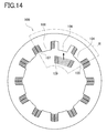
- a stator core 100 as shown in FIG 14 , when a last coil 109 is to be mounted on a teeth part 108, the last coil 109 interferes with a firstly mounted coil 105 and a coil 107 which are to be adjacent to the coil 109.
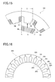
- the mounting width S of the coil 109 is wider than the mountable width U between the adjacent coils 105 and 107.
- the last coil 109 could not be mounted on the teeth part 108.
- the last coil 109 could not be mounted on the teeth part 108.
- stator core 200 described in Patent Document 1 shown in FIG 16 .
- stator parts 201 of the stator core 200 are formed, on an inner peripheral side, with teeth parts 203.
- Slits 206 are formed on both sides of each stator part 201.
- the outer periphery of each stator part 201 is pressed or pushed. This causes deformation of each stator part 201 allowed by the slits 206 formed on both sides of each stator part 201.
- Patent Documents 2 and 3 also disclose the inventions related to mounting of teeth parts on coils.
- the stator core 200 has a problem that the stator parts 201 have to be pushed one by one for each teeth part 203 to mount the bundled coil wires on the teeth parts 203. Therefore, in a case of the teeth parts 203 provided at twelve places in the whole circumference, the outer periphery of the stator parts 201 have to be pushed twelve times so that the coil is mounted on the teeth parts 203. Such twelve-times pushing of the outer periphery of the stator parts 201, increasing the number of steps, results in deteriorated productivity.
- the slits 206 are formed over the whole circumference of the inner periphery. Due to the slits 206 formed in the whole circumference, the circularity of the stator core 200 and the parallelism of end faces of the stator core 200 are deteriorated.
- the stator-core circularity represents the circularity of a hollow cylindrical stator core.
- the end-face parallelism represents the parallelism of an end face forming an inner wall of the hollow part of the hollow cylindrical stator core with respect to a central axis.
- stator core and a rotor set in the hollow part of the stator core are controlled in three dimensions to avoid the stator core and the rotor from bumping or colliding with each other.
- the rotor has to be reduced in size to prevent bumping or colliding with the stator core.
- Such a size-reduced rotor generates a wide gap between the stator core and the rotor and thus a magnetic flux density between the stator core and the rotor lowers. This results in a decrease in motor power.
- the circularity and the end-face parallelism of the stator core 200 are deteriorated for the following reasons.
- the stator part 201 is allowed to be deformed by the slits 206.
- each stator part 201 returns to an original position by a restoring force.
- the stator parts 201 actually have different restoring forces because of the slits 206 arranged over the whole circumference. Therefore, the circularity and the end-face parallelism of the stator core 200 are deteriorated by the total of differences in restoring force depending on the slits 206.
- stator structure 1 as shown in FIG. 1 in which a stator core made of core steel plates laminated or stacked and formed with a yoke part 12 and teeth parts T, and coils are mounted around the teeth parts T.
- a cut section 50 is formed at only one place of the yoke part 12. Since the cut section 50 formed at only one place, coils C are allowed to be mounted on the teeth parts T while keeping the circularity and the end-face parallelism.
- the stator structure 1 enables mounting of a coil C12 on a last teeth part T12 by separating the cut section 50.
- the cut section 50 is opened within an elastically deformable range of the stator core.
- the cut section 50 can return to an original state with high circularity and high end-face parallelism by elastic force without becoming plastically deformed.
- Patent Documents 4 to 9 fail to disclose a manufacturing method including forming a cut section in a yoke part.
- the forming method of the cut section was intended to form the cut section after forming a thin steel plate in a progressive press process and then producing a stator-core steel plate.
- a first problem is that, when the cut section is formed after the progressive press process, a step using a cutting tool such as wire cutting is required after punching, pressing or crimping, and laminating. This results in an increase in cost.
- a second problem is that, when the cut section is formed in the progressive press process, the yoke part is distorted. Specifically, the cut section is formed, not by punching out a part of the yoke part, by pressing a punch to make a cut in the yoke part at one place. Accordingly, when the cut section is formed in such a manner that one end of the yoke part having an almost annular shape is fixed by a die and a retainer and the other end is cut by a punch, the other end portion pressed by the punch is pressed and plastically deformed. This causes distortion. Due to such a distortion, the magnetic characteristics of the stator core made up of the laminated stator-core steel plates is deteriorated and hence the performance of a motor as a finished product is degraded.
- the present invention has been made to solve the above problems and has a first purpose to provide a stator manufacturing method with reduced cost, and a second purpose to provide a stator manufacturing method for manufacturing a stator having a yoke part including a cut section with reduced distortion.
- one aspect of the invention provides a stator core manufacturing method configured as below.
- the cut section extending in the radial direction can be formed at only one place in the circumferential direction of each of the core steel plates in the progressive press process. Since the cut sections can be formed in the progressive press process, there is no need to provide additional equipment for performing a cutting equipment step. Thus, cost reduction can be achieved.
- the cut positions of the cut sections can be changed according to the rotary lamination angles of the core steel plates. Since the cut positions of the cut sections are changed according to the rotary lamination angles, the cut sections can be provided even when the core steel plates are stacked by rotary lamination.
- the core steel plates can be formed with the cut positions changed by a predetermined amount. Since the core steel plates with the cut positions changed by the predetermined amount are formed, a finished stator core can be provided with an engagement protrusion and an engagement recess. Thus, when the stator core is elastically deformed, displacement of the stator core in the lamination direction can be restrained. Since the displacement in the lamination direction is reduced, the stator core can return to an original shape with high circularity and high end-face parallelism.
- each cut section can be formed promptly.
- the plurality of cutting punches are provided and those cutting punches are switched between operation and non-operation, so that the cut sections can be formed without changing the positions of the core steel plates. This makes it possible to promptly form the core steel plates having the cut sections.
- the core steel plates formed with the cut sections can be produced at low cost. Specifically, the cut section is moved so that the cut sections can be formed without changing the positions of the core steel plates. This case where the cutting punch is moved is lowest in cost as compared with the case where a plurality of cutting punches are installed and the case where the positions of the core steel plates are changed. Thus, the core steel plates formed with the cut sections can be produced at low cost.
- the core steel plates can be produced in which one end and the other end of each core steel plate, as both ends of each cut section to be formed in the cut section forming step, are located on the same position.
- the pilot hole forming step is provided before the cut section forming step to form the cut section after the pilot hole is formed in the core steel plate. Therefore, reaction force is generated in the core steel plate, thereby allowing the one end and the other end of the core steel plate to be placed at the same level without plastically deforming the core steel plate.
- a necessary area of a steel plate can be made small. Specifically, since the lateral width of the pilot hole can be shortened because of the pilot hole made in a long hole, the area of the steel plate can be reduced.
- stator core including a configuration of a cut section and a method for forming the cut section
- a configuration of a coil will be explained.
- a method for mounting the coil onto the stator core will be explained to thereby explain a method for manufacturing a stator.
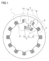
- FIG 1 is a diagram showing a step (1) of mounting a coil C in a stator core 1.
- FIG 2 is a diagram showing a step (2) of mounting the coil C in the stator core 1.
- FIG 3 is a partial enlarged view of a part enclosed by a chain line P in FIG 1 .
- FIG 4 is a partial enlarged view of a part enclosed by a chain line Q in FIG 2 .
- FIG 5 is a diagram showing a step (3) of mounting the coil C in the stator core 1.
- the stator core 1 in FIG 1 is made of a plurality of stator-core thin steel plates 80 ("core steel plates” in claims) laminated or stacked in two or more layers and in a hollow cylindrical shape.
- the steel plates 80 will be explained later.
- the stator core 1 has a diameter of 200 mm.
- the twelve teeth parts T are referred to as a first teeth part T1, a second teeth part T2, ...., and a twelfth teeth part T12.
- the teeth parts T support twelve coils C each of which is formed of a conductor wire having a flat rectangular cross section and wound in more than one turn.
- the coils C include twelve coils C in correspondence with the twelve teeth parts T.
- the twelve coils C are referred to as a first coil C1, a second coil C2, ...., and a twelfth coil C12.
- the stator core 1 is formed with a cut section 50 extending in a radial direction.
- the cut section 50 is formed through all the thin steel plates.
- the cut section 50 includes one end 51 formed on a first teeth part T1 side of the yoke part 12 and the other end 52 formed on a twelfth teeth part T2 side of the yoke part 12. Opening of the cut section 50 therefore means that the one end 51 and the other end 52 are separated from each other. While no force is applied to the cut section 50, as shown in FIGs. 1 and 3 , the one end 51 and the other end 52 are in contact with each other.
- the cut section 50 is opened in an elastically deformable range of the core 1, generating a gap L as shown in FIG 4 .
- the width of the gap L is a distance from the one end 51 to the other end 52 of the cut section 50.
- the width of the gap L in the present embodiment is about 3 mm. Because this about 3-mm width of the gap L corresponds to the elastically deformable range and falls in a range that does not have any influence on circularity and parallelism of end faces (end-face parallelism) after the stator core 1 returns to its original shape by its elasticity (elastic force).
- the gap L when the gap L is generated by a width of about 3 mm, it can provide a distance long enough to insert the last twelfth coil C12 on the last twelfth teeth part T12. In the stator core 1 having a diameter of 200 mm, such a mere about 3-mm width of the gap L hardly influences the circularity and the end-face parallelism.
- the width of the gap L is set to about 3 mm in the present embodiment
- the width of the gap L is not limited to about 3 mm as long as it is in the elastically deformable range and in a region in which the stator core 1 is not plastically deformed.
- the elastically deformable range may be changed according to the materials of the stator core 1 and also according to the size of the stator core 1.
- the width of the gap L is not limited to about 3 mm set in the present embodiment.
- the width of the gap L has only to be determined as a width allowing the last twelfth coil C12 to be mounted on the last twelfth teeth part T12. According to the cases where the number of teeth parts is increased to 18, 24, etc. or decreased to 9 or 6 as alternatives to the present embodiment including twelve teeth parts, the width of the gap L is changed.
- the width of the gap L to open the cut section 50 is illustrated to be large as a conceptual diagram to facilitate understanding thereof. Actually, the width of the gap L is as small as about 3 mm.
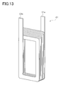
- FIG 13 is an external perspective view of the first coil C1. Although FIG 13 describes the first coil C1, the second coil C2 to the twelfth coil C12 are also configured similarly.
- the first coil C1 is a coil made by edgewise bending a flat rectangular conductor wire by use of an edgewise bending wiring device not shown.
- the first coil C1 has a first end portion C1a and a second end portion C1b.
- One of the first end portion C1a and the second end portion C1b is a winding starting end and the other is a winding ending end.
- the first coil C1 is formed of a wire wound in a nearly trapezoidal shape so that short sides are gradually longer as the wire is wound to the first end portion C1a side.
- an edgewise coil is explained as the finished first coil C1.
- FIG 17 shows a first step of the manufacturing method of the stator-core steel plates 80.
- FIG 18 shows a second step,
- FIG 19 shows a third step, and
- FIG 20 shows a fourth step.
- the method for manufacturing the stator-core steel plates 80 is a method to produce stator-core steel plates 80 shown in FIG 20 .
- Each steel plate 80 has a yoke part 81 having a hollow circular shape and teeth parts Z formed on an inner circumferential surface of the yoke part 81.
- the steel plate 80 has a diameter of 200 mm and a thickness of 2 to 3 mm.
- twelve teeth parts Z are formed at a predetermined pitch.
- the twelve teeth parts of the teeth part Z are referred to as a first teeth part Z1, a second teeth part Z2, ...., a twelfth teeth part Z12.
- the reference signs of a fourth teeth part Z4 to the twelfth teeth part Z12 are omitted in FIG 20 .
- a first pre-shaped steel plate 91 not shown is a thin steel plate before being subjected to a first step.
- a first step by a press work, an inner diameter hole piece 91A which defines the teeth parts Z is punched out from the first pre-shaped steel plate 91 and thus a second pre-shaped steel plate 92 is formed.
- the first step is performed using an inner diameter hole forming device which is a press working device not shown.
- the second pre-shaped steel plate 92 from which the inner diameter hole piece 91A has been removed is formed with an inner diameter hole 92A.
- the teeth parts Z are thus provided along the inner diameter hole 92A.
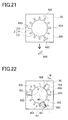
- a pilot hole piece 92B is punched out from the second pre-shaped steel plate 92 to form a pilot hole 92C.
- the second step is performed by using a pilot hole forming device which is a press working device not shown.
- the pilot hole piece 92B is a part located between two teeth parts Z to face the yoke part 81.
- the pilot hole piece 92B has a long hole shape having long sides and short sides. Further, a long side 921C of the long hole shape, close to the inner diameter hole 92A, is in a position almost parallel to an inner circumferential side 811 between teeth parts Z of the steel plate 80 which is a finished product shown in FIG 20 .
- the long side 921C near the inner diameter hole 92A is located in a portion out of contact with an outer periphery 801 of the steel plate 80 as shown in FIG 20 . This is to avoid the shape of the pilot hole 92C from remaining in the outer periphery 801 of the steel plate 80 which is a final shape after the steel plate 80 is subjected to a press work in a fourth step.
- the punching press work of the pilot hole piece 92B in the second step is performed at an interval of 120°.
- the second pre-shaped steel plate 92 is subjected to a press work to form one of pilot holes 92C, 92D, and 92E which are arranged at 120° intervals.
- the pilot hole 92C is formed and thus the pilot holes 92D and 92E are not formed and illustrated with dashed chain lines.
- the pilot holes 92C, 92D, and 92E are formed at 120° intervals. Forming the pilot hole at 120° intervals is because, when the steel plates 80 are to be laminated to produce a stator core, they are stacked by rotary lamination to enhance cylindricality of the stator core. For this rotary lamination of the steel plates 80 by 120° , the pilot holes formed at intervals of 120°.
- the pilot holes 92C, 92D, and 92E are formed by a pilot hole forming device not shown.
- the pilot holes 92C, 92D, and 92E are formed at intervals of 120°, so that the pilot hole forming device not shown is placed in three positions in front of the second pre-shaped steel plate 92 in correspondence with the pilot holes 92C, 92D, and 92E shown in FIG 21 . While the pilot hole forming devices are set in three places and one of them is operated, the remaining pilot hole forming devices are held in non-operation state.
- each of the pilot holes 92C, 92C, or 92E can be formed by punching out the pilot hole piece 92B at intervals of 120° without moving the second pre-shaped steel plates 92.
- a cut section 90 is formed to extend from the inner peripheral side 811 of the inner diameter hole 92A between the steel-plate teeth parts Z of the steel plate 80 to the pilot hole 92C.
- one end 932 of the second pre-shaped steel plate 92 to form the cut section 90 is pinched and fixed between a retainer 76 and a die 77.
- the other end 931 to form the cut section 90 is pressed by a cutting punch 75.
- the cut section 90 is formed in the second pre-shaped steel plate 92, and a third pre-shaped steel plate 93 shown in FIG 19 is produced.
- the cutting punch 75, the retainer 76, and the die 77 constitute a cut section forming machine 700.
- a distance between the inner peripheral side 811 of the steel plate between the teeth parts Z of the yoke part and the long side 921 of the pilot hole 92C is short.
- the third pre-shaped steel plate 93 is fixed by the retainer 76 and the die 77 and to be cut by the cutting punch 75, distortion which may be caused in the third pre-shaped steel plate 93 can be reduced.
- the distance between the inner peripheral side 811 between the teeth parts Z and the long side 921 of the pilot hole 92C is short, the area to be pressed by the cutting punch 75 and thus the distortion of the third pre-shaped steel plate 93 is decreased.
- the one end 932 and the other end 931 are made farthest by the press work. In the present embodiment, however, even when the other end 931 is pressed by the cutting punch 75 in cutting work and thus receives a downward load, the other end 931 can return to a position at the same level as the one end 932 by reaction force. In other words, the distance between the inner peripheral side 811 between the teeth parts Z and the long side 921 of the pilot hole 92C to form the cut section 90 is short. However, excepting the distance from the inner peripheral side 811 between the teeth parts Z to the long side 921C of the pilot hole 92C, the distance from the inner peripheral side 811 between the teeth parts Z to an outer periphery 920 of the second pre-shaped steel plate 92 is long.
- a distance from the inner peripheral side 811 between the teeth parts Z to the outer periphery 920 of the steel plate 92 is long in most part. Having the long distance, even when the most part is applied with a downward load in a cutting work, the most part provide reaction force against the load. Because of the reaction force, the other end 931 can return to the position at the same level as the one end 932. Since the other end 931 returns to the same level position as the one end 932, the stator-core steel plate 80 is not distorted.
- stator-core steel plate 80 shown in FIG 20 is not formed with the cut section 90 and is subjected to a press work to make the cut section 90, the inner peripheral side 811 between the teeth parts Z and the long side 921C of the pilot hole 92C is short.
- distortion may be generated. This is because, when the pilot hole 92C is not formed, the distance between the inner peripheral side 811 between the teeth parts Z and the outer periphery 801 of the steel plate 80 is equal over the entire circumference. Further, the distance between the inner peripheral side 811 between the teeth parts Z and the outer periphery 801 of the steel plate 80 is short over the entire circumference.
- the cut section 90 is formed by the cutting punch 75 while no pilot hole 92C is formed, distortion is caused due to the short distance over the entire circumference between the inner peripheral side 811 between the teeth parts Z and the outer periphery 801 of the steel plate 80.
- the one end 932 and the other end 931 are made farthest in the press work, but the other press 931 is pressed and subjected to the downward load in a cutting work.
- the other end 932 attempts to return by its reaction force, but cannot fully return to an original position because of insufficient reaction force resulting from the short distance between the inner peripheral side 811 between the teeth parts Z and the outer periphery 801 of the steel plate 80 throughout the entire circumference.
- distortion is generated.
- the cut section 90 is formed by a press work using the cut section forming machines 700 to extend from the inner diameter hole 92A to the pilot hole 92C.
- FIG 22 only cutting punches 751, 752, and 753 of the cut section forming machines 700 are illustrated.
- the cutting punches 751, 752, and 753 are arranged in three positions when seen in a front direction of the second pre-shaped steel plate 92 as shown in FIG 22 . Specifically, the cutting punches 751, 752, and 753 are placed in the position corresponding to the pilot hole 92C, 92 formed in three places in the second step and at intervals of 120° around the center.
- the cutting punch 753 which is one of the cut section forming machines 700 placed in three positions spaced at intervals of 120°, is placed in a position displaced by a predetermined amount W from one of dashed chain lines V for marking off at intervals of 120° as shown in FIG 22 .
- the position of the cutting punch 753 displaced by the predetermined amount W is defined at a position +4 mm from the dashed chain line V marked at the intervals of 120°.
- the cut section forming machines 700 are disposed in three positions. While one of the cut section forming machines 700 is in operation, the remaining machines 700 are in non-operation. Accordingly, the cut section 90 can be formed in the second pre-shaped steel plate 92 held as is without being moved.
- the cutting punch 753 is positioned +4 mm displaced from the dashed chain line V for segmentalization of 120° intervals. Accordingly, when the stator-core steel plates 80 are laminated to produce a stator core 300 as shown in FIG 25 , an engagement protrusion 301 and an engagement recess 302 are provided in the stator core 300. Since the engagement protrusion 301 and the engagement recess 302 are formed, if the stator core 300 is elastically deformed to open a cut section 310 by 3 mm, the stator core 300 is prevented from becoming displaced in a lamination direction. This allows the stator core 300 to return to its original shape with high circularity and high end-face parallelism.
- the engagement protrusion 301 and the engagement recess 302, each having 4 mm are not disengaged from each other and thus can serve to guide.
- the engagement protrusion 301 and the engagement recess 302 serving as a guide, the cut section 310 can be fully returned to its original position.
- the stator core 300 can be returned to its original shape with high circularity and high end-face parallelism without being plastically deformed.
- the stator core 300 formed with the engagement protrusion 301 and the engagement recess 302 will be further explained in detail in a third embodiment.
- the second pre-shaped steel plate 92 is formed with caulking portions 933, 934, and 935 at three positions in the yoke part 81 at intervals of 120° and at a base of the corresponding teeth part Z.
- those caulking portions 933, 934, and 935 allow the steel plates 80 to be fixed in a predetermined position. Since the steel plates 80 are fixed in the predetermined position, the cut sections 90 are positioned in the same places, thus forming the cut section 50 shown in FIG 1 .
- the cut section 50 can be elastically deformed as shown in FIG 2 .
- the caulking portions are formed in three positions, but they may be provided at one place, two places, or three or more places as long as they contribute to fix the laminated steel plates 80 in a predetermined position.
- the stator-core steel plate 80 is punched out from the third pre-shaped steel plate 93 by a press work as shown in FIG 20 .
- the stator-core steel plate 80 is thus produced.
- the fourth step uses a steel plate punching machine which is a press working device not shown.
- the long side 921C of the inner diameter hole 92A is located in a portion out of contact with the outer periphery 801 of the stator-core steel plate 80 as shown in FIG 20 . Therefore, after the steel plate 80 is subjected to the press work, the shape of the pilot hole 92C is not left in the steel plate 80.
- FIG. 24 is a conceptual diagram of the push-out punch 78.
- This punch 78 is formed with engagement protrusions 78A configured to engage with the caulking portions 933, 934, and 935. Accordingly, after a stator-core steel plate 80A is punched out of the third pre-shaped steel plate 93, the engagement protrusion 78A is engaged in caulking portions 935B, 935C, and 935D of punched-out steel plates 80B, 80C, and 80D to fix them.
- the first step an inner diameter hole forming step of forming the inner diameter hole 92A in the second pre-shaped steel plate 92 to form steel-plate teeth parts Z in the stator-core steel plate 80.
- the second step (a pilot hole forming step) is provided to form the pilot hole 92C at one place of the second pre-shaped steel plate 92, outside the outer periphery 801 of the part corresponding to the stator-core steel plate 80 which is to be punched out.
- the third step (a cut section forming step) is provided to form the cut section 90 to extend from the inner diameter hole 92A to the pilot hole 92C.
- the fourth step (a steel plate punching step) to punch the stator-core steel plate 80 out of the third pre-shaped steel plate 93. Because of the presence of the above four steps, it is possible to reduce distortion which may be generated in the steel-plate yoke part 81. Specifically, the stator-core steel plate 80 produced by the inner diameter hole forming step, the pilot hole forming step, the cut section forming step, and the steel plate punching step can be manufactured with less distortion. To be more concrete, the stator-core steel plate 80 can be manufactured in which the one end 932 and the other end 931 of the steel plate 80, which are both ends of the cut section 90 formed in the cut section forming step, are located at the same level as each other.
- the pilot hole forming step is performed before the cut section forming step to form the cut section 90 in the stator-core steel plate 80 formed with the pilot hole 92C, thereby causing the reaction force in the steel plate 80, so that the one end 932 and the other end 931 of the steel plate 80 can be located at the same position or level as each other without causing plastic deformation.
- about two hundred stator-core steel plates 80 are laminated to produce the stator 1. Since the one and 931 and the other end 932 of each stator-core steel plate 80 are located at the same level as each other, even when a plurality of stator-core steel plates 80 are laminated, no gap is generated between the steel plates 80.
- the pressing force to press the stator 1 can be reduced. This can reduce iron loss which is apt to be caused by large pressing force. Because of the steel plates 80 with no gap therebetween, the stator 1 can provide enhanced magnetic characteristics. Thus, the performance of the stator 1 can be increased.
- the plurality of cutting punches 751, 752, and 753 are provided to be used in the cut section forming step according to the rotary lamination angle of the stator-core steel plates 80.
- the cutting punches 751, 752, and 753 are operated or not operated.
- the position of the cutting punch 753 is displaced by the predetermined amount W in the circumferential direction from the position according to the rotary lamination angle.
- the engagement protrusion 301 and the engagement recess 302 can be easily formed in the cut section 310.
- two kinds of stator-core steel plates 80 having different cut sections are required.
- the position of the cutting punch 753 is displaced by the predetermined amount W in the circumferential direction from the position corresponding to the rotary lamination angle, so that two kinds of the stator-core steel plates 80 having different cut sections can be easily produced.
- cut section 931 can be formed in the progressive press process, there is no need to additionally provide any equipment used for the cutting equipment step. Thus, cost reduction can be achieved.
- the cut position of the cut section 931 can be changed according to the rotary lamination angle of the stator-core steel plates 80.
- the cut section 931 can be formed in place even when the stator-core steel plates 80 are stacked by rotary lamination.
- the stator-core steel plates 80 can be produced with the cut positions changed by the predetermined amount. Since the steel plates 80 with the cut positions different by the predetermined amount are produced, for example, the engagement protrusion 33 and the engagement recess 34 can be formed in the stator core 3 shown in FIG 3 . Accordingly, when the stator core 3 is elastically deformed, the stator core 3 can be prevented from becoming displaced in the lamination direction. This makes it possible to return the stator core 3 to its original shape with high circularity and high end-face parallelism.
- each stator-core steel plate 80 formed with the cut section 931 can be formed promptly.
- the stator-core steel plates 80 are stacked in layers by rotary lamination so that the cut positions of the cut sections 931 are changed according to the rotary lamination angle of the stator-core steel plates 80 and the cut positions of the cut sections 931 are changed by the predetermined amount in the circumferential direction. This can change the cut positions of the cut sections 931 according to the rotary lamination angle of the stator core stators 80. Because of the cut positions changed according to the rotary lamination angle, each cut section 931 can be formed in the predetermined position even when the stator-core steel plates 80 are stacked by rotary lamination.
- stator-core steel plates 80 with the cut positions changed by the predetermined amount can be produced. Since the stator-core steel plates 80 with the cut positions changed by the predetermined amount are produced, for example, the engagement protrusion 33 and the engagement recess 34 can be formed in the finished stator core 3 shown in FIG 3 . Accordingly, in the case where the stator core 3 is elastically deformed, it is possible to restrain displacement of the stator core 3 in the lamination direction. Restraining the displacement in the lamination direction allows the stator core 3 to return to its original shape with high circularity and high end-face parallelism.
- a plurality of cutting punches are provided.
- the cutting punch 75 may be moved.
- the stator-core steel plates 80 formed with the cut sections 931 can be formed at low cost.
- the cut sections 931 can be formed by moving the cut sections 931 without the need to change the position of the stator-core steel plates 80. Moving the cutting punch 75 is lowest in cost as compared with the case where a plurality of cut sections 931 are formed or where the positions of the stator-core steel plates 80 are changed. Consequently, the stator-core steel plates 80 with the cut sections 931 can be produced at low cost.
- the stator-core steel plates 80 are laminated or stacked to produce the stator core 1. As shown in FIG 1 , the coils C are sequentially mounted on the teeth parts T of the stator core 1. To be concrete, the first coil C1 is mounted on the first teeth part T1 formed in one end of the cut section 50, the second coil C2 is mounted on the second teeth part T2, ...., so that eleven coils C are mounted sequentially on eleven teeth parts T.
- a mounting width H which is defined as a mounting width of the twelfth coil C12 on a first end portion C12a side is wider than a mountable width J defined from the second end portion C1b of the first coil C1 to a second end portion C11b of the eleventh coil C11 to receive a coil.
- a pull force in a circumferential direction is applied to the cut section 50 of the stator core 1.
- both end portions of the cut section 50 of the yoke part 12 are grasped from above and below and moved apart from each other in the circumferential direction.
- the circumferential pull force exerted on the cut section 50 elastically deforms the stator core 1.
- the cut section 50 is opened in the elastically deformable range, thereby generating the gap L.
- the width of the gap L in the present embodiment is a distance of about 3 mm.
- the width from the second end portion C1b of the first coil C1 to the second end portion C11b of the eleventh coil C11 is widened from the mountable width J to a mountable width K.
- the distance determined by subtracting the mountable width J from the mountable width K is proportional to the width of the gap L.
- the mountable width K from the second end portion C1b of the first coil C1 to the second end portion C11b of the eleventh coil C11 is larger than the mounting width H of the twelfth coil C12 on the side of the first end portion C12a. Therefore, the twelfth coil C 12 can be mounted on the twelfth teeth part T12 without being interfered by the first coil C1 and the eleventh coil C11.
- the circumferential pull force exerted on the cut section 50 is removed.
- the stator core 1 Upon removal of the pull force, the stator core 1 returns by its elasticity to its original state shown in FIG 5 .
- the stator core 1 returns to the original state shown in FIG 5 , the one end 51 and the other end 52 of the cut section 50 are brought in contact with each other, and the gap L disappears. Since the gap L disappears, the first coil C1 and the twelfth coil C12 come close to each other.
- the stator core 1 comes to the state shown in FIG 5 by the elasticity and therefore does not cause plastic deformation. Because of no plastic deformation, the stator core 1 can maintain the circularity and the end-face parallelism of the original stator core 1.
- the gap L can be generated without affecting the circularity and the end-face parallelism of the stator core 1.
- the reason thereof is as below. Since the stator core 1 is applied with the pull force in the elastically deformable range, the stator core 1 will return to its original shape by its elasticity. Therefore, the circularity and the end-face parallelism of the stator core 1 remain unchanged from those obtained before application of the pull force.
- the pull force is exerted in such a range as not to make the gap wider than about 5 mm.
- the stator core 1 is plastically deformed and thus cannot return to its original shape by the elasticity. Accordingly, the pull force in the range causing no plastic deformation is applied to the stator core 1.
- stator core 1 in the first embodiment As explained in detail above, according to the stator core 1 in the first embodiment, the following advantageous effects can be provided.
- the cut section 50 is formed only at one place of the yoke part 12, it is possible to mount the coils C on the teeth parts T while maintaining the circularity and the end-face parallelism. The reason thereof is as below.
- the last coil 109 could not be mounted on the last teeth part 108.
- the cut section 50 is opened to allow mounting of the twelfth coil C12 on the last twelfth teeth part T12.
- this opening of the cut section 50 is performed in the elastically deformable range of the stator core 1.
- the cut section 50 is not plastically deformed and the stator core 1 can return, by the elasticity, to its original shape having high circularity and high end-face parallelism.
- the cut section 50 Since the cut section 50 is formed only at one place, it is possible to directly mount the first coil C1 and others on the first teeth part T1 and others without opening the cut section 50 except for the case where the twelfth coil C12 is to be mounted on the twelfth teeth part T12. Accordingly, the cut section 50 has only to be opened only once in order to mount the twelfth coil C12 on the twelfth teeth part T12, so that the circularity and the end-face parallelism remain unchanged. Only one-time opening the cut section 50 makes it possible to enhance an assembling efficiency and reduce a manufacturing cost.
- Opening the cut section 50 allows the twelfth coil C12 to be easily mounted on the twelfth teeth part T12.
- the reason thereof is as below.
- the stator core 1 is made of laminated or stacked steel plates and thus has low rigidity. This allows the cut section 50 to be easily opened by a few of millimeters in the elastically deformable range. Since the cut section 50 formed in the yoke part 12 beside the twelfth teeth part T12 is allowed to be easily opened, the gap corresponding to the mountable width J needed to mount the twelfth coil C12 can be generated.
- the cut section 50 In the case where the cut section 50 is opened by a few of three millimeters in the elastically deformable range, when the cut section 50 is to be allowed to return to its original shape, the cut section 50 will naturally return to the original shape by the elasticity of the yoke part 12. Accordingly, the cut section 50 can easily return to the original shape without needing application of a returning force thereto. This can reduce a manufacturing cost.
- a stator core 2 in a second embodiment is different from the stator core 1 in the first embodiment only in that a cut section 20 of the stator core 2 is different in shape from the cut section 50 of the stator core 1.
- the second embodiment is identical to the first embodiment except for the cut section and therefore will be explained with a focus on the cut section 20 without repeating the explanation of other parts or components.
- FIG. 6 is a partial enlarged view of a shape (1) of the cut section 20 of the stator core 2.
- the stator core 2 is formed with the cut section 20 extending in a radial direction.
- the cut section 20 is formed through all the thin steel plates.
- the cut section 20 includes one end 21 formed on the first teeth part T1 side of the yoke part 12 and the other end 22 formed on the twelfth teeth part T12 side of the yoke part 12. Opening the cut section 20 therefore means that the one end 21 and the other end 22 are separated from each other. While no force is applied to the cut section 20, the one end 21 and the other end 22 are in contact with each other.
- the one end 21 may be formed with an engagement protrusion 23 having a curved surface at a distal end and the other end 22 may be formed with an engagement recess 24 having a curved surface engageable with the engagement protrusion 23.
- the protrusion 23 and the recess 24 are formed in a radial direction X.
- the protrusion 23 has a length N longer than a width of the gap L by which the cut section 20 is allowed to open.
- a depth of the recess 24 engaging with the protrusion 23 is equal to the length N of the protrusion 23. For instance, if the width of the gap L is about 3 mm, the length N of the protrusion 23 and the depth of the recess 24 are respectively set to be 4 mm or more.
- FIG 7 is a partial enlarged view of a shape (2) of the cut section 20 of the stator core 2.
- the shape of the cut section 20 is not limited to the shape having such a curved end as shown in FIG 6 and may be a shape having a triangular end as shown in FIG 7 .
- the cut section 20 may be formed with an engagement protrusion 25 having a triangular protruding shape and an engagement recess 26 having a triangular recessed shape engageable with the protrusion 25.
- These protrusion 25 and recess 26 are formed in a radial direction X.
- the protrusion 25 has a length N longer than a width of the gap L by which the cut section 20 is allowed to open.
- a depth of the recess 26 engaging with the protrusion 25 is equal to the length N of the protrusion 25. For instance, if the width of the gap L is about 3 mm, the length of the protrusion 25 and the depth of the recess 26 are respectively set to be 4 mm or more.
- the reason thereof is as below. While the cut section 20 having been opened is fully returning to its original shape by the elasticity, the protrusion 23 and the recess 24 serve as a guide for the returning motion. Owing to the protrusion 23 and the recess 24, the cut section 20 can return to its original position. Since the cut section 20 can return to the original position, the stator core 2 can return to a shape having high circularity and high end-face parallelism without being plastically deformed.
- the length N of the engagement protrusion 23 and the engagement recess 24 is set to 4 mm or more, which is longer than the width of the gap L of about 3 mm for opening the cut section 20, so that the protrusion 23 does not disengage from the recess 24 during coil assembling. Accordingly, the protrusion 23 and the recess 24 can serve as a guide to prevent the stator core 2 from disassembling.
- the stator core 2 having the protrusion 23 and the recess 24 in the radial direction X can be made by use of a single press die used for shaping a steel plate. Since the stator core 2 having the protrusion 23 and the recess 24 can be manufactured by use of the single press die, a manufacturing cost can be reduced than in the case where engagement portions are formed in a lamination direction. This is because, to manufacture the stator core having the engagement portions in the lamination direction, steel plates have to be made in at least two patterns.
- engagement protrusion 25 and the engagement recess 26 shown in FIG 7 are formed, they can provide the same effects as the engagement protrusion 23 and the engagement recess 24 having curved end faces shown in FIG 6 .
- a stator core 3 in a third embodiment is different from the stator core 1 in the first embodiment only in that the shape of a cut section 30 of the stator core 3 is different from the shape of the cut section 50 of the stator core 1.
- the third embodiment is identical to the first embodiment except for the cut section and thus is explained with a focus on the cut section 30 without repeating the explanation of other parts or components.
- FIG 8 is an external perspective view of the stator core 3 in the third embodiment.
- FIG 9 is a partial enlarged view of a part of the stator core 3 enclosed by a dashed-chain line D in FIG 8 .
- the stator core 3 is formed with the cut section 30 extending in a radial direction as shown in FIG 8 .
- the cut section 30 is formed through all the thin steel plates and thus is opened or separated when a pull force is applied to the stator core 3.
- the cut section 30 includes one end 31 formed on the first teeth part T1 side of the yoke part 12 and the other end 32 formed on the twelfth teeth part T12 side of the yoke part 12. Opening the cut section 30 therefore means that the one end 31 and the other end 32 are separated from each other. While no force is applied to the cut section 30, the one end 31 and the other end 32 are in contact with each other as shown in FIG 8 .
- the one end 31 may be formed with an engagement protrusion 33 and the other end 32 may be formed with an engagement recess 34 engageable with the protrusion 33.
- the protrusion 33 and the recess 34 are formed in a lamination direction Y
- the protrusion 33 has a length M longer than a width of the gap L by which the cut section 30 is allowed to open.
- the recess 34 engaging with the protrusion 33 has a depth equal to the length M of the protrusion 33. For instance, in the case where the width of the gap L is about 3 mm, the length M of the protrusion 33 and the depth of the recess 34 are respectively set to be 4 mm or more.
- stator core 3 Owing to the presence of the engagement protrusion 33 and the engagement recess 34 formed as shown in FIGs. 8 and 9 , it is possible to restrain displacement of the stator core 3 in the lamination direction Y in FIG 9 when the stator core 3 is elastically deformed. Since the displacement in the lamination direction Y is prevented, the stator core 3 can return to its original shape with high circularity and high end-face parallelism.
- the reason thereof is as below.
- the protrusion 33 and the recess 34 serve as a guide to fully return the opened cut section 30 to an original position. With those protrusion 33 and recess 34, the cut section 30 can return completely to the original position. Consequently, the stator core 3 can return to the shape having high circularity and high end-face parallelism without causing plastic deformation.
- the protrusion 33 Since the length M of the engagement protrusion 33 and the engagement recess 34 is longer than the width of the gap L for opening the cut section 30 during coil assembling, the protrusion 33 does not disengage from the recess 34. Therefore, the protrusion 33 and the recess 34 can serve as a guide to prevent the stator core 3 from disassembling.
- the thickness of the stator core 3 in the lamination direction is larger than the thickness in the radial direction, so that the protrusion 33 and the recess 34 can be formed in two or more places in the lamination direction.
- the third embodiment includes the protrusion 33 and the recess 34 each at one place but may include a plurality of engagement protrusions and a plurality of engagement recesses. In the case of including the engagement protrusions and the engagement recesses, the cut section 30 can fully return to the original position more reliably.
- a stator core 4 in a fourth embodiment is different from the stator core 1 in the first embodiment only in that the stator core 4 is formed with a one-end protrusion 41 and an other-end protrusion 42 each protruding outward from the yoke part 12.
- the fourth embodiment is explained with a focus on a cut section 70 without repeating explanation of other parts or components.
- FIG 10 is a front view of the stator core 4 in the fourth embodiment.
- FIG 11 is a partial enlarged view (1) of a part enclosed by a chain line E in FIG 10 in the fourth embodiment.
- FIG 12 is a partial enlarged view (2) of the part enclosed by the chain line E in FIG 10 in the fourth embodiment.
- the one-end protrusion 41 and the other-end protrusion 42 are formed each protruding outward from the outer periphery of the yoke part 12.
- the one-end protrusion 41 is formed on a side of one end 71 of both end portions of the cut section 70, while the other-end protrusion 42 is formed on a side of the other end 72 of both end portions of the cut section 70.
- the one-end protrusion 41 and the other-end protrusion 42 constitute an outward protruding portion 40.
- a one-end gap forming recess 43 of a semielliptic shape is formed in a contact surface of the one-end protrusion 41 that contacts with the other-end protrusion 42.
- An other-end gap forming recess 44 of a semielliptic shape is formed in a contact surface of the other-end protrusion 42 that contacts with the one-end protrusion 41.
- the recesses are provided as through holes, but may be formed in a concave or recessed shape, not a through hole shape.
- the one-end protrusion 41 and the other-end protrusion 42 are used in the second step to open the cut section 70 from a closed position shown in FIG 11 to generate a gap L as shown in FIG 12 .
- the gap L in the fourth embodiment is about 3 mm.
- the stator core 4 in the fourth embodiment is formed with the one-end gap forming recess 43 of a semielliptic shape in the contact surface of the one-end protrusion 41 that contacts with the other-end protrusion 42 and the other-end gap forming recess 44 of a semielliptic shape in the contact surface of the other-end protrusion 42 that contacts with the one-end protrusion 41.
- an elliptic cylindrical tool 60 is inserted in the hollow elliptic cylindrical though hole defined by the recesses 43 and 44.
- the tool 60 has a size smaller than the elliptic cylindrical through hole and thus can be inserted in the through hole.
- the tool 60 is inserted in the through hole and then rotated 90° about a center point F.
- the one-end protrusion 41 and the other-end protrusion 42 are separated from each other by a distance corresponding to a value obtained by subtracting a minor axis 60B from a major axis 60A of the elliptic shape. Accordingly, the simple 90°-rotation of the elliptic cylindrical tool 60 makes it easy to open the cut section 70.
- the one-end protrusion 41 and the other-end protrusion 42 can be separated accurately by the distance corresponding to the value obtained by subtracting the minor axis 60B from the major axis 60A of the elliptic shape.
- the tool 60 it is possible to accurately apply a force to the stator core 4 in an elastically deformable range.
- the tool 60 can therefore be returned to its original position without causing plastic deformation of the stator core 4.
- the stator core 4 can maintain the circularity and the end-face parallelism at the same level as before the use of the tool 60.
- the one-end protrusion 41 and the other-end protrusion 42 are moved apart from each other.
- the cut section 70 can therefore be easily opened.
- the cut section 70 is formed with the one-end protrusion 41 and the other-end protrusion 42, the cut section 70 can be opened while keeping the circularity and the end-face parallelism of the stator core 4.
- the reason thereof is as below.
- the one-end protrusion 41 and the other-end protrusion 42 are formed on the outer periphery of the yoke part 12 needing to maintain the circularity and end-face parallelism. Therefore, the cut section 70 can be opened while keeping the circularity and the end-face parallelism of the yoke part 12 more reliably in the case where the one-end protrusion 41 and the other-end protrusion 42 formed on the outer periphery of the yoke part 12 are separated than in the case where the yoke part 12 needing to maintain the circularity and end-face parallelism is directly opened.
- the yoke part 12 When a force is directly applied to the yoke part 12, the yoke part 12 may be deformed, resulting in that the circularity and end-face parallelism cannot be maintained. However, when a force is directly applied to the one-end protrusion 41 and the other-end protrusion 42 formed on the outer periphery of the yoke part 12, the yoke part 12 needing to maintain the circularity and the end-face parallelism is not deformed. Thus, the circularity and the end-face parallelism can be kept.
- separating the one-end protrusion 41 and the other-end protrusion 42 formed on the outer periphery of the yoke part 12 is easier than directly separating the yoke part 12 by application of a force thereto.
- outward protruding portion 40 formed distantly from the stator core 4 needs only a small force to open the cut section 70. Accordingly, opening the outward protruding portion 40 can easily open the cut section 70 formed in the yoke part 12. This can enhance the assembling efficiency to mount the twelfth coil C12 on the last twelfth teeth part T12 and also reduce the manufacturing cost.
- it may combine the engagement protrusion and the engagement recess in the radial direction in the second embodiment with the engagement protrusion and the engagement recess in the lamination direction in the third embodiment.
- This combination of both configurations allows the cut section to fully return to the original position more reliably when returning by the elasticity.
- stator cores in the first to fourth embodiments may be configured in combination.
- the combined configurations can also provide operations and advantageous effects obtainable from respective features.
- the pilot hole 92C shown in FIG 21 may be formed in a long rectangular slit shape. Because of the long rectangular hole shape, a required steel plate area can be reduced. Since the width of a pilot hole having such a long hole shape can be set narrow, the area of a pre-shaped steel plate can be made close to the size of the stator-core steel plate 80 which is a finished product. Thus, pre-shaped steel plate can be designed smaller. This reduced size results in savings in material cost and reduction in total cost.
- the plurality of cutting punches 75 are provided.
- the cut section can be formed according to the rotary lamination angle of the stator-core steel plates and the cut section can be formed shifted by a predetermined amount in a circumferential direction.
- the stator-core steel plates 80 formed with the cut sections can be produced at low cost.
Landscapes
- Engineering & Computer Science (AREA)
- Power Engineering (AREA)
- Manufacturing & Machinery (AREA)
- Manufacture Of Motors, Generators (AREA)
- Iron Core Of Rotating Electric Machines (AREA)
Abstract
Description
- The present invention relates to a stator core manufacturing method for forming a stator core made of core steel plates which are progressively formed in a progressive press process so that each of the steel plates has a yoke part and teeth parts, and laminated or stacked one on another.
- Some stator cores are configured such that coils are mounted or fitted on teeth parts of the stator core. The circularity of the stator core (stator-core circularity) and the parallelism of end faces (end-face parallelism) of the stator core are determined depending on press accuracy. Therefore, a one-piece stator core made of steel plates which can be produced by a single press work can easily enhance the stator-core circularity and the end-face parallelism as compared with a split stator core produced by assembling split core pieces individually.
- The one-piece stator core is manufactured for example by mounting edgewise coils on teeth parts in sequence. However, for a
stator core 100, as shown inFIG 14 , when alast coil 109 is to be mounted on ateeth part 108, thelast coil 109 interferes with a firstly mountedcoil 105 and acoil 107 which are to be adjacent to thecoil 109. Specifically, as illustrated inFIG 15 showing an enlarged view of a part indicated by a chain line R inFIG 14 , the mounting width S of thecoil 109 is wider than the mountable width U between theadjacent coils last coil 109 could not be mounted on theteeth part 108. - Therefore, in the case where the coils are mounted on the teeth parts in sequence, the
last coil 109 could not be mounted on theteeth part 108. - As this type of technique, conventionally, there is a
stator core 200 described inPatent Document 1 shown inFIG 16 . As shown inFIG 16 ,stator parts 201 of thestator core 200 are formed, on an inner peripheral side, withteeth parts 203.Slits 206 are formed on both sides of eachstator part 201. When bundled coil wires are to be mounted on theteeth parts 203 of thestator parts 201, the outer periphery of eachstator part 201 is pressed or pushed. This causes deformation of eachstator part 201 allowed by theslits 206 formed on both sides of eachstator part 201. When onestator part 201 is externally pushed, thereby widening theslits 206, thecorresponding teeth part 203 is made to protrude inward. Since eachteeth part 203 is caused to protrude inward, the bundled coil wires are allowed to be mounted thereon. - As above, the
stator parts 201 are externally pushed one by one in sequence and the bundled coil wires are allowed to be mounted on theteeth parts 203. In addition,Patent Documents -
- Patent Document 1:
JP 2000-245081 A - Patent Document 2:
JP 2001-251819 A - Patent Document 3:
JP 2006-352991 A - Patent Document 4:
JP 2000-243624 A - Patent Document 5:
JP 2009-118676 A - Patent Document 6:
JP 2006-352991 A - Patent Document 7:
JP 2004-023964 A - Patent Document 8:
JP 2002-238231 A - Patent Document 9:
JP 2000-184630 A - However, the conventional arts have the following problems. Specifically, the
stator core 200 has a problem that thestator parts 201 have to be pushed one by one for eachteeth part 203 to mount the bundled coil wires on theteeth parts 203. Therefore, in a case of theteeth parts 203 provided at twelve places in the whole circumference, the outer periphery of thestator parts 201 have to be pushed twelve times so that the coil is mounted on theteeth parts 203. Such twelve-times pushing of the outer periphery of thestator parts 201, increasing the number of steps, results in deteriorated productivity. - In the
stator core 200, theslits 206 are formed over the whole circumference of the inner periphery. Due to theslits 206 formed in the whole circumference, the circularity of thestator core 200 and the parallelism of end faces of thestator core 200 are deteriorated. The stator-core circularity represents the circularity of a hollow cylindrical stator core. The end-face parallelism represents the parallelism of an end face forming an inner wall of the hollow part of the hollow cylindrical stator core with respect to a central axis. Based on the stator-core circularity and the end-face parallelism, the stator core and a rotor set in the hollow part of the stator core are controlled in three dimensions to avoid the stator core and the rotor from bumping or colliding with each other. - If the stator-core circularity and the end-face parallelism are low, the rotor has to be reduced in size to prevent bumping or colliding with the stator core. Such a size-reduced rotor generates a wide gap between the stator core and the rotor and thus a magnetic flux density between the stator core and the rotor lowers. This results in a decrease in motor power.
- The circularity and the end-face parallelism of the
stator core 200 are deteriorated for the following reasons. When the outer periphery of eachstator part 201 is pushed, thestator part 201 is allowed to be deformed by theslits 206. When pushing eachstator part 201 is stopped, eachstator part 201 returns to an original position by a restoring force. Although eachstator part 201 returns to its original shape by the restoring force, thestator parts 201 actually have different restoring forces because of theslits 206 arranged over the whole circumference. Therefore, the circularity and the end-face parallelism of thestator core 200 are deteriorated by the total of differences in restoring force depending on theslits 206. - Therefore, the present applicant proposed a
stator structure 1 as shown inFIG. 1 in which a stator core made of core steel plates laminated or stacked and formed with ayoke part 12 and teeth parts T, and coils are mounted around the teeth parts T. In thisstator structure 1, acut section 50 is formed at only one place of theyoke part 12. Since thecut section 50 formed at only one place, coils C are allowed to be mounted on the teeth parts T while keeping the circularity and the end-face parallelism. - This is because, as shown in
FIG 2 , thestator structure 1 enables mounting of a coil C12 on a last teeth part T12 by separating thecut section 50. In separating, then thecut section 50 is opened within an elastically deformable range of the stator core. As long as the separation width is within the elastically deformable range of the stator core, thecut section 50 can return to an original state with high circularity and high end-face parallelism by elastic force without becoming plastically deformed. - However,
Patent Documents 4 to 9 fail to disclose a manufacturing method including forming a cut section in a yoke part. - In the
above stator structure 1 proposed by the present applicant, furthermore, the forming method of the cut section was intended to form the cut section after forming a thin steel plate in a progressive press process and then producing a stator-core steel plate. However, a first problem is that, when the cut section is formed after the progressive press process, a step using a cutting tool such as wire cutting is required after punching, pressing or crimping, and laminating. This results in an increase in cost. - A second problem is that, when the cut section is formed in the progressive press process, the yoke part is distorted. Specifically, the cut section is formed, not by punching out a part of the yoke part, by pressing a punch to make a cut in the yoke part at one place. Accordingly, when the cut section is formed in such a manner that one end of the yoke part having an almost annular shape is fixed by a die and a retainer and the other end is cut by a punch, the other end portion pressed by the punch is pressed and plastically deformed. This causes distortion. Due to such a distortion, the magnetic characteristics of the stator core made up of the laminated stator-core steel plates is deteriorated and hence the performance of a motor as a finished product is degraded.
- The present invention has been made to solve the above problems and has a first purpose to provide a stator manufacturing method with reduced cost, and a second purpose to provide a stator manufacturing method for manufacturing a stator having a yoke part including a cut section with reduced distortion.
- To achieve the above purpose, one aspect of the invention provides a stator core manufacturing method configured as below.
- (1) In a method for manufacturing a stator core, in which core steel plates each having a yoke part and teeth parts are sequentially formed and the core steel plates are laminated one on another to produce the stator core, the method includes: forming a cut section extending in a radial direction in each of the core steel plates in the progressive press process so that the cut section is located at only one place in a circumferential direction.
- (2) In the stator core manufacturing method described in (1), preferably, the stator core is made of the core steel plates stacked by rotary lamination, and a cut position of each cut section to be formed is changed according to an angle of rotary lamination of the core steel plates.
- (3) In the stator core manufacturing method described in (1), preferably, the cut position of the cut section is changed by a predetermined amount in the circumferential direction.
- (4) In the stator core manufacturing method described in (2) or (3), preferably, a plurality of cutting punches are provided to form the cut sections, and the cutting punches are able to be switched between operation and non-operation.
- (5) In the stator core manufacturing method described in (2) or (3), preferably, the cutting punch is moved.
- (6) The stator core manufacturing method described in (1) to (5), preferably, further includes: an inner diameter hole forming step of forming the teeth parts and an inner diameter hole in a pre-shaped steel plate and in an inner circumference of each core steel plate; a pilot hole forming step of forming a pilot hole at one place of the pre-shaped steel plate in an outer peripheral portion outside a portion of the pre-shaped steel plate to be punched out as the core steel plate; a cut section forming step of forming the cut section to extend from the inner diameter hole to the pilot hole; and a steel plate punching step of punching out the core steel plate from the pre-shaped steel plate.
- (7) In the stator core manufacturing method described in (6), preferably, the pilot hole has a long hole shape.
- (8) Another aspect of the invention provides a stator core manufacturing apparatus for manufacturing a stator core made of core steel plates each including a yoke part and teeth parts, the core steel plates being sequentially formed by a progressive press process and laminated one on another, wherein the apparatus includes a cutting punch to form a cut section extending in a radial direction in each of the core steel plates in the progressive press process so that the cut section is located at only one place in a circumferential direction.
- (9) In the stator core manufacturing apparatus described in (8), preferably, a cut position of each cut section to be formed is changed according to an angle of rotary lamination of the core steel plates.
- (10) In the stator core manufacturing apparatus described in (8), preferably, the cutting punch is moved in the circumferential direction to the cut position.
- (11) In the stator core manufacturing apparatus described in (9) or (10), preferably, a plurality of cutting punches are provided, and the cutting punches are able to be switched between operation and non-operation.
- (12) The stator core manufacturing apparatus described in (8) to (11) preferably includes: an inner diameter hole forming unit to form the teeth parts and an inner diameter hole in a pre-shaped steel plate and in an inner circumference of each core steel plate; a pilot hole forming unit to form a pilot hole at one place of the pre-shaped steel plate in an outer peripheral portion outside a portion of the pre-shaped steel plate to be punched out as the core steel plate; and a steel plate punching unit to punch out the core steel plate from the pre-shaped steel plate.
- (13) In the stator core manufacturing apparatus described in (12), preferably, the pilot hole forming unit is arranged to form the pilot hole having a long hole shape.
- With the above configuration (1) or (8), the cut section extending in the radial direction can be formed at only one place in the circumferential direction of each of the core steel plates in the progressive press process. Since the cut sections can be formed in the progressive press process, there is no need to provide additional equipment for performing a cutting equipment step. Thus, cost reduction can be achieved.
- With the above configuration (2) or (9), the cut positions of the cut sections can be changed according to the rotary lamination angles of the core steel plates. Since the cut positions of the cut sections are changed according to the rotary lamination angles, the cut sections can be provided even when the core steel plates are stacked by rotary lamination.
- With the above configuration (3) or (10), the core steel plates can be formed with the cut positions changed by a predetermined amount. Since the core steel plates with the cut positions changed by the predetermined amount are formed, a finished stator core can be provided with an engagement protrusion and an engagement recess. Thus, when the stator core is elastically deformed, displacement of the stator core in the lamination direction can be restrained. Since the displacement in the lamination direction is reduced, the stator core can return to an original shape with high circularity and high end-face parallelism.
- With the above configuration (4) or (11), each cut section can be formed promptly. Specifically, the plurality of cutting punches are provided and those cutting punches are switched between operation and non-operation, so that the cut sections can be formed without changing the positions of the core steel plates. This makes it possible to promptly form the core steel plates having the cut sections.
- With the above configuration (5), the core steel plates formed with the cut sections can be produced at low cost. Specifically, the cut section is moved so that the cut sections can be formed without changing the positions of the core steel plates. This case where the cutting punch is moved is lowest in cost as compared with the case where a plurality of cutting punches are installed and the case where the positions of the core steel plates are changed. Thus, the core steel plates formed with the cut sections can be produced at low cost.
- With the above configuration (6) or (12), it is possible to reduce distortion of each core steel plate generated in forming the cut sections in the core steel plates in the progressive press process. Specifically, the core steel plates can be produced in which one end and the other end of each core steel plate, as both ends of each cut section to be formed in the cut section forming step, are located on the same position. This results from that the pilot hole forming step is provided before the cut section forming step to form the cut section after the pilot hole is formed in the core steel plate. Therefore, reaction force is generated in the core steel plate, thereby allowing the one end and the other end of the core steel plate to be placed at the same level without plastically deforming the core steel plate.
- With the above configuration (7) or (13), a necessary area of a steel plate can be made small. Specifically, since the lateral width of the pilot hole can be shortened because of the pilot hole made in a long hole, the area of the steel plate can be reduced.
-
-
FIG 1 is a diagram showing a step (1) of mounting a coil in a stator core in a first embodiment of the invention; -
FIG 2 is a diagram showing a step (2) of mounting the coil in the stator core in the first embodiment of the invention; -
FIG 3 is a partial enlarged view of a part enclosed by a chain line P inFIG 1 in the first embodiment of the invention; -
FIG 4 is a partial enlarged view of a part enclosed by a chain line Q inFIG 2 in the first embodiment of the invention; -
FIG 5 is a diagram showing a step (3) of mounting the coil in the stator core in the first embodiment of the invention; -
FIG 6 is a partial enlarged view of a shape (1) of a cut section in a second embodiment of the invention; -
FIG 7 is a partial enlarged of a shape (2) of the cut section in the second embodiment of the invention; -
FIG 8 is a perspective external view of a stator core in a third embodiment of the invention; -
FIG 9 is a partial enlarged view of a part enclosed by a chain line D inFIG 8 in the third embodiment t of the invention; -
FIG 10 is a front view of a stator core in a fourth embodiment of the invention; -
FIG 11 is a partial enlarged view (1) of a part enclosed by a chain line E inFIG 10 in the fourth embodiment of the invention; -
FIG 12 is a partial enlarged view (2) of the part enclosed by the chain line E inFIG 10 in the fourth embodiment of the invention; -
FIG 13 is a perspective external view of a coil in the first embodiment of the invention; -
FIG 14 is a diagram showing a step of mounting a coil in a stator core in a conventional art; -
FIG 15 is a partial enlarged view of a part enclosed by a chain line R inFIG. 14 in the conventional art; -
FIG 16 is a partial enlarged view of a stator core in a Patent Document ; -
FIG 17 is a conceptual plan view of a forming step (1) of a cut section in examples 1 to 4 of the invention; -
FIG 18 is a conceptual plan view of a forming step (2) of the cut section in first to fourth examples of the invention; -
FIG 19 is a conceptual plan view of a forming step (3) of the cut section in examples the first to fourth examples of the invention; -
FIG 20 is a conceptual plan view of a forming step (4) of the cut section in the first to fourth examples of the invention; -
FIG 21 is a conceptual plan view of a forming part for a pilot hole in the forming step (2) of the cut section in the first to fourth examples of the invention; -
FIG 22 is a conceptual plan view showing a position of a cutting punch in the forming step (3) of the cut section in the first to fourth examples of the invention; -
FIG 23 is a conceptual cross sectional view of a cut section forming machine for forming a cut section in the first to fourth examples of the invention; -
FIG 24 is a partial conceptual cross sectional view of a push-out punch for a stator-core steel plate in the forming step (4) of the cut section in the first to fourth examples of the invention; and -
FIG 25 is an outer perspective view of a stator core produced by a manufacturing method for the cut section in the first to fourth examples of the invention; - Firstly, a configuration of a stator core (including a configuration of a cut section and a method for forming the cut section) will be explained. Secondly, a configuration of a coil will be explained. Thirdly, a method for mounting the coil onto the stator core will be explained to thereby explain a method for manufacturing a stator.
-
FIG 1 is a diagram showing a step (1) of mounting a coil C in astator core 1.FIG 2 is a diagram showing a step (2) of mounting the coil C in thestator core 1.FIG 3 is a partial enlarged view of a part enclosed by a chain line P inFIG 1 .FIG 4 is a partial enlarged view of a part enclosed by a chain line Q inFIG 2 .FIG 5 is a diagram showing a step (3) of mounting the coil C in thestator core 1. - The
stator core 1 inFIG 1 is made of a plurality of stator-core thin steel plates 80 ("core steel plates" in claims) laminated or stacked in two or more layers and in a hollow cylindrical shape. Thesteel plates 80 will be explained later. In the present embodiment, thestator core 1 has a diameter of 200 mm. On the inner peripheral surface of thestator core 1, there are formed twelve teeth parts T at a predetermined pitch. The twelve teeth parts T are referred to as a first teeth part T1, a second teeth part T2, ...., and a twelfth teeth part T12. - The teeth parts T support twelve coils C each of which is formed of a conductor wire having a flat rectangular cross section and wound in more than one turn. In the present embodiment, the coils C include twelve coils C in correspondence with the twelve teeth parts T. The twelve coils C are referred to as a first coil C1, a second coil C2, ...., and a twelfth coil C12.
- As shown in
FIG 1 , thestator core 1 is formed with acut section 50 extending in a radial direction. Thecut section 50 is formed through all the thin steel plates. When a pull force is applied to thestator core 1, thestator core 1 is elastically deformed as shown inFIG 2 , thus opening thecut section 50. Thecut section 50 includes oneend 51 formed on a first teeth part T1 side of theyoke part 12 and theother end 52 formed on a twelfth teeth part T2 side of theyoke part 12. Opening of thecut section 50 therefore means that the oneend 51 and theother end 52 are separated from each other. While no force is applied to thecut section 50, as shown inFIGs. 1 and3 , the oneend 51 and theother end 52 are in contact with each other. - When the
stator core 1 is elastically deformed by application of the pull force, thecut section 50 is opened in an elastically deformable range of thecore 1, generating a gap L as shown inFIG 4 . The width of the gap L is a distance from the oneend 51 to theother end 52 of thecut section 50. The width of the gap L in the present embodiment is about 3 mm. Because this about 3-mm width of the gap L corresponds to the elastically deformable range and falls in a range that does not have any influence on circularity and parallelism of end faces (end-face parallelism) after thestator core 1 returns to its original shape by its elasticity (elastic force). Further, when the gap L is generated by a width of about 3 mm, it can provide a distance long enough to insert the last twelfth coil C12 on the last twelfth teeth part T12. In thestator core 1 having a diameter of 200 mm, such a mere about 3-mm width of the gap L hardly influences the circularity and the end-face parallelism. - Although the width of the gap L is set to about 3 mm in the present embodiment, the width of the gap L is not limited to about 3 mm as long as it is in the elastically deformable range and in a region in which the
stator core 1 is not plastically deformed. Specifically, the elastically deformable range may be changed according to the materials of thestator core 1 and also according to the size of thestator core 1. Thus, the width of the gap L is not limited to about 3 mm set in the present embodiment. - Furthermore, the width of the gap L has only to be determined as a width allowing the last twelfth coil C12 to be mounted on the last twelfth teeth part T12. According to the cases where the number of teeth parts is increased to 18, 24, etc. or decreased to 9 or 6 as alternatives to the present embodiment including twelve teeth parts, the width of the gap L is changed.
- In
FIGs. 2 and4 , the width of the gap L to open thecut section 50 is illustrated to be large as a conceptual diagram to facilitate understanding thereof. Actually, the width of the gap L is as small as about 3 mm. -
FIG 13 is an external perspective view of the first coil C1. AlthoughFIG 13 describes the first coil C1, the second coil C2 to the twelfth coil C12 are also configured similarly. - As shown in
FIG 13 , the first coil C1 is a coil made by edgewise bending a flat rectangular conductor wire by use of an edgewise bending wiring device not shown. The first coil C1 has a first end portion C1a and a second end portion C1b. One of the first end portion C1a and the second end portion C1b is a winding starting end and the other is a winding ending end. The first coil C1 is formed of a wire wound in a nearly trapezoidal shape so that short sides are gradually longer as the wire is wound to the first end portion C1a side. - In the present embodiment, an edgewise coil is explained as the finished first coil C1. The same applies to any other types of coils having finished shapes, irrespective of what shape the cross section has, circular or rectangular.
- A method for manufacturing stator-
core steel plates 80 will be explained below referring tofigs. 17 to 20 . The stator core is produced in a progressive press process.FIG 17 shows a first step of the manufacturing method of the stator-core steel plates 80.FIG 18 shows a second step,FIG 19 shows a third step, andFIG 20 shows a fourth step. - The method for manufacturing the stator-
core steel plates 80 is a method to produce stator-core steel plates 80 shown inFIG 20 . Eachsteel plate 80 has ayoke part 81 having a hollow circular shape and teeth parts Z formed on an inner circumferential surface of theyoke part 81. In the present embodiment, thesteel plate 80 has a diameter of 200 mm and a thickness of 2 to 3 mm. On the inner circumferential surface of thesteel plate 80, twelve teeth parts Z are formed at a predetermined pitch. The twelve teeth parts of the teeth part Z are referred to as a first teeth part Z1, a second teeth part Z2, ...., a twelfth teeth part Z12. The reference signs of a fourth teeth part Z4 to the twelfth teeth part Z12 are omitted inFIG 20 . - A first pre-shaped steel plate 91 not shown is a thin steel plate before being subjected to a first step. In the first step, by a press work, an inner
diameter hole piece 91A which defines the teeth parts Z is punched out from the first pre-shaped steel plate 91 and thus a secondpre-shaped steel plate 92 is formed. The first step is performed using an inner diameter hole forming device which is a press working device not shown. As shown inFIG 17 , the secondpre-shaped steel plate 92 from which the innerdiameter hole piece 91A has been removed is formed with aninner diameter hole 92A. The teeth parts Z are thus provided along theinner diameter hole 92A. - In a second step, as shown in
FIG 18 , by a press work, apilot hole piece 92B is punched out from the secondpre-shaped steel plate 92 to form apilot hole 92C. The second step is performed by using a pilot hole forming device which is a press working device not shown. Thepilot hole piece 92B is a part located between two teeth parts Z to face theyoke part 81. To be concrete, thepilot hole piece 92B has a long hole shape having long sides and short sides. Further, along side 921C of the long hole shape, close to theinner diameter hole 92A, is in a position almost parallel to an innercircumferential side 811 between teeth parts Z of thesteel plate 80 which is a finished product shown inFIG 20 . Thelong side 921C near theinner diameter hole 92A is located in a portion out of contact with anouter periphery 801 of thesteel plate 80 as shown inFIG 20 . This is to avoid the shape of thepilot hole 92C from remaining in theouter periphery 801 of thesteel plate 80 which is a final shape after thesteel plate 80 is subjected to a press work in a fourth step. - The punching press work of the
pilot hole piece 92B in the second step is performed at an interval of 120°. Specifically, as shown inFIG 21 , the secondpre-shaped steel plate 92 is subjected to a press work to form one ofpilot holes FIG 21 , thepilot hole 92C is formed and thus thepilot holes steel plates 80 are to be laminated to produce a stator core, they are stacked by rotary lamination to enhance cylindricality of the stator core. For this rotary lamination of thesteel plates 80 by 120° , the pilot holes formed at intervals of 120°. - The pilot holes 92C, 92D, and 92E are formed by a pilot hole forming device not shown. The pilot holes 92C, 92D, and 92E are formed at intervals of 120°, so that the pilot hole forming device not shown is placed in three positions in front of the second
pre-shaped steel plate 92 in correspondence with thepilot holes FIG 21 . While the pilot hole forming devices are set in three places and one of them is operated, the remaining pilot hole forming devices are held in non-operation state. Thus, each of thepilot holes pilot hole piece 92B at intervals of 120° without moving the secondpre-shaped steel plates 92. - In a third step, as shown in
FIG 19 , by a press work, acut section 90 is formed to extend from the innerperipheral side 811 of theinner diameter hole 92A between the steel-plate teeth parts Z of thesteel plate 80 to thepilot hole 92C. To be concrete, as shown inFIG 23 , oneend 932 of the secondpre-shaped steel plate 92 to form thecut section 90 is pinched and fixed between aretainer 76 and adie 77. Successively, theother end 931 to form thecut section 90 is pressed by a cuttingpunch 75. When pressed by the cuttingpunch 75, thecut section 90 is formed in the secondpre-shaped steel plate 92, and a thirdpre-shaped steel plate 93 shown inFIG 19 is produced. The cuttingpunch 75, theretainer 76, and the die 77 constitute a cutsection forming machine 700. - In the present embodiment, when the
cut section 90 is to be formed, a distance between the innerperipheral side 811 of the steel plate between the teeth parts Z of the yoke part and the long side 921 of thepilot hole 92C is short. Thus, when the thirdpre-shaped steel plate 93 is fixed by theretainer 76 and thedie 77 and to be cut by the cuttingpunch 75, distortion which may be caused in the thirdpre-shaped steel plate 93 can be reduced. Specifically, since the distance between the innerperipheral side 811 between the teeth parts Z and the long side 921 of thepilot hole 92C is short, the area to be pressed by the cuttingpunch 75 and thus the distortion of the thirdpre-shaped steel plate 93 is decreased. - Furthermore, the one
end 932 and theother end 931 are made farthest by the press work. In the present embodiment, however, even when theother end 931 is pressed by the cuttingpunch 75 in cutting work and thus receives a downward load, theother end 931 can return to a position at the same level as the oneend 932 by reaction force. In other words, the distance between the innerperipheral side 811 between the teeth parts Z and the long side 921 of thepilot hole 92C to form thecut section 90 is short. However, excepting the distance from the innerperipheral side 811 between the teeth parts Z to thelong side 921C of thepilot hole 92C, the distance from the innerperipheral side 811 between the teeth parts Z to anouter periphery 920 of the secondpre-shaped steel plate 92 is long. Accordingly, a distance from the innerperipheral side 811 between the teeth parts Z to theouter periphery 920 of thesteel plate 92 is long in most part. Having the long distance, even when the most part is applied with a downward load in a cutting work, the most part provide reaction force against the load. Because of the reaction force, theother end 931 can return to the position at the same level as the oneend 932. Since theother end 931 returns to the same level position as the oneend 932, the stator-core steel plate 80 is not distorted. - If the stator-
core steel plate 80 shown inFIG 20 is not formed with thecut section 90 and is subjected to a press work to make thecut section 90, the innerperipheral side 811 between the teeth parts Z and thelong side 921C of thepilot hole 92C is short. However, when thecut section 90 is formed in such asteel plate 80 by the press work, distortion may be generated. This is because, when thepilot hole 92C is not formed, the distance between the innerperipheral side 811 between the teeth parts Z and theouter periphery 801 of thesteel plate 80 is equal over the entire circumference. Further, the distance between the innerperipheral side 811 between the teeth parts Z and theouter periphery 801 of thesteel plate 80 is short over the entire circumference. Accordingly, if thecut section 90 is formed by the cuttingpunch 75 while nopilot hole 92C is formed, distortion is caused due to the short distance over the entire circumference between the innerperipheral side 811 between the teeth parts Z and theouter periphery 801 of thesteel plate 80. Specifically, the oneend 932 and theother end 931 are made farthest in the press work, but theother press 931 is pressed and subjected to the downward load in a cutting work. Theother end 932 attempts to return by its reaction force, but cannot fully return to an original position because of insufficient reaction force resulting from the short distance between the innerperipheral side 811 between the teeth parts Z and theouter periphery 801 of thesteel plate 80 throughout the entire circumference. Thus, distortion is generated. - In the present embodiment, the
cut section 90 is formed by a press work using the cutsection forming machines 700 to extend from theinner diameter hole 92A to thepilot hole 92C. InFIG 22 , only cuttingpunches section forming machines 700 are illustrated. The cutting punches 751, 752, and 753 are arranged in three positions when seen in a front direction of the secondpre-shaped steel plate 92 as shown inFIG 22 . Specifically, the cutting punches 751, 752, and 753 are placed in the position corresponding to thepilot hole - In the present embodiment, furthermore, the cutting
punch 753, which is one of the cutsection forming machines 700 placed in three positions spaced at intervals of 120°, is placed in a position displaced by a predetermined amount W from one of dashed chain lines V for marking off at intervals of 120° as shown inFIG 22 . InFig. 22 , only the cutting punches of the cutsection forming machines 700 are illustrated and other components are omitted, butretainers 76 and dies 77 are similarly placed. In the present embodiment, the position of the cuttingpunch 753 displaced by the predetermined amount W is defined at a position +4 mm from the dashed chain line V marked at the intervals of 120°. The cutsection forming machines 700 are disposed in three positions. While one of the cutsection forming machines 700 is in operation, the remainingmachines 700 are in non-operation. Accordingly, thecut section 90 can be formed in the secondpre-shaped steel plate 92 held as is without being moved. - The cutting
punch 753 is positioned +4 mm displaced from the dashed chain line V for segmentalization of 120° intervals. Accordingly, when the stator-core steel plates 80 are laminated to produce astator core 300 as shown inFIG 25 , anengagement protrusion 301 and anengagement recess 302 are provided in thestator core 300. Since theengagement protrusion 301 and theengagement recess 302 are formed, if thestator core 300 is elastically deformed to open acut section 310 by 3 mm, thestator core 300 is prevented from becoming displaced in a lamination direction. This allows thestator core 300 to return to its original shape with high circularity and high end-face parallelism. This is because when thecut section 310 separated by 3 mm fully returns to its original position, theengagement protrusion 301 and theengagement recess 302, each having 4 mm, are not disengaged from each other and thus can serve to guide. With theengagement protrusion 301 and theengagement recess 302 serving as a guide, thecut section 310 can be fully returned to its original position. Thus, thestator core 300 can be returned to its original shape with high circularity and high end-face parallelism without being plastically deformed. Thestator core 300 formed with theengagement protrusion 301 and theengagement recess 302 will be further explained in detail in a third embodiment. - As shown in
FIG 19 , in the third step, the secondpre-shaped steel plate 92 is formed withcaulking portions yoke part 81 at intervals of 120° and at a base of the corresponding teeth part Z. When the stator-core steel plates 80 are laminated, accordingly, thosecaulking portions steel plates 80 to be fixed in a predetermined position. Since thesteel plates 80 are fixed in the predetermined position, thecut sections 90 are positioned in the same places, thus forming thecut section 50 shown inFIG 1 . Thecut section 50 can be elastically deformed as shown inFIG 2 . In the present embodiment, the caulking portions are formed in three positions, but they may be provided at one place, two places, or three or more places as long as they contribute to fix thelaminated steel plates 80 in a predetermined position. - In a fourth step, the stator-
core steel plate 80 is punched out from the thirdpre-shaped steel plate 93 by a press work as shown inFIG 20 . The stator-core steel plate 80 is thus produced. The fourth step uses a steel plate punching machine which is a press working device not shown. Thelong side 921C of theinner diameter hole 92A is located in a portion out of contact with theouter periphery 801 of the stator-core steel plate 80 as shown inFIG 20 . Therefore, after thesteel plate 80 is subjected to the press work, the shape of thepilot hole 92C is not left in thesteel plate 80. - In the fourth step, a push-
out punch 78 shown inFIG 24 is used.FIG. 24 is a conceptual diagram of the push-out punch 78. Thispunch 78 is formed withengagement protrusions 78A configured to engage with thecaulking portions core steel plate 80A is punched out of the thirdpre-shaped steel plate 93, theengagement protrusion 78A is engaged incaulking portions steel plates FIG 24 , when thecaulking portion 93 5A of thesteel plate 80A and thecaulking portion 935B of thesteel plate 80B are pushed out by thepunch 78 when moved downward, simultaneously, thesteel plates - As explained above in detail, there is included the first step (an inner diameter hole forming step) of forming the
inner diameter hole 92A in the secondpre-shaped steel plate 92 to form steel-plate teeth parts Z in the stator-core steel plate 80. The second step (a pilot hole forming step) is provided to form thepilot hole 92C at one place of the secondpre-shaped steel plate 92, outside theouter periphery 801 of the part corresponding to the stator-core steel plate 80 which is to be punched out. The third step (a cut section forming step) is provided to form thecut section 90 to extend from theinner diameter hole 92A to thepilot hole 92C. The fourth step (a steel plate punching step) to punch the stator-core steel plate 80 out of the thirdpre-shaped steel plate 93. Because of the presence of the above four steps, it is possible to reduce distortion which may be generated in the steel-plate yoke part 81. Specifically, the stator-core steel plate 80 produced by the inner diameter hole forming step, the pilot hole forming step, the cut section forming step, and the steel plate punching step can be manufactured with less distortion. To be more concrete, the stator-core steel plate 80 can be manufactured in which the oneend 932 and theother end 931 of thesteel plate 80, which are both ends of thecut section 90 formed in the cut section forming step, are located at the same level as each other. This is because the pilot hole forming step is performed before the cut section forming step to form thecut section 90 in the stator-core steel plate 80 formed with thepilot hole 92C, thereby causing the reaction force in thesteel plate 80, so that the oneend 932 and theother end 931 of thesteel plate 80 can be located at the same position or level as each other without causing plastic deformation. In the present embodiment, about two hundred stator-core steel plates 80 are laminated to produce thestator 1. Since the one and 931 and theother end 932 of each stator-core steel plate 80 are located at the same level as each other, even when a plurality of stator-core steel plates 80 are laminated, no gap is generated between thesteel plates 80. Therefore, when thestator 1 is to be molded, the pressing force to press thestator 1 can be reduced. This can reduce iron loss which is apt to be caused by large pressing force. Because of thesteel plates 80 with no gap therebetween, thestator 1 can provide enhanced magnetic characteristics. Thus, the performance of thestator 1 can be increased. - Furthermore, the plurality of cutting
punches core steel plates 80. The cutting punches 751, 752, and 753 are operated or not operated. The position of the cuttingpunch 753 is displaced by the predetermined amount W in the circumferential direction from the position according to the rotary lamination angle. As shown inFIG. 25 , theengagement protrusion 301 and theengagement recess 302 can be easily formed in thecut section 310. Specifically, to form protrusions and recesses in thecut section 310, two kinds of stator-core steel plates 80 having different cut sections are required. According to the present invention, however, the position of the cuttingpunch 753 is displaced by the predetermined amount W in the circumferential direction from the position corresponding to the rotary lamination angle, so that two kinds of the stator-core steel plates 80 having different cut sections can be easily produced. - Since the
cut section 931 can be formed in the progressive press process, there is no need to additionally provide any equipment used for the cutting equipment step. Thus, cost reduction can be achieved. - By changing the cut position of the
cut section 931 according to the rotary lamination angle of the stator-core steel plates 80, the cut position of thecut section 931 can be changed according to the rotary lamination angle of the stator-core steel plates 80. By changing the cut position according to the rotary lamination angle, thecut section 931 can be formed in place even when the stator-core steel plates 80 are stacked by rotary lamination. - Since the cut position of the
cut section 931 is changed by the predetermined amount in the circumferential direction, the stator-core steel plates 80 can be produced with the cut positions changed by the predetermined amount. Since thesteel plates 80 with the cut positions different by the predetermined amount are produced, for example, theengagement protrusion 33 and theengagement recess 34 can be formed in thestator core 3 shown inFIG 3 . Accordingly, when thestator core 3 is elastically deformed, thestator core 3 can be prevented from becoming displaced in the lamination direction. This makes it possible to return thestator core 3 to its original shape with high circularity and high end-face parallelism. - Since a plurality of cutting
punches 75 to form thecut section 931 are provided. These cutting punches 75 are switchable between operation and non-operation. Thus, thecut section 931 can be formed without changing the position of the stator-core steel plates 80 in the progressive press process. Accordingly, each stator-core steel plate 80 formed with thecut section 931 can be formed promptly. - The stator-
core steel plates 80 are stacked in layers by rotary lamination so that the cut positions of thecut sections 931 are changed according to the rotary lamination angle of the stator-core steel plates 80 and the cut positions of thecut sections 931 are changed by the predetermined amount in the circumferential direction. This can change the cut positions of thecut sections 931 according to the rotary lamination angle of thestator core stators 80. Because of the cut positions changed according to the rotary lamination angle, eachcut section 931 can be formed in the predetermined position even when the stator-core steel plates 80 are stacked by rotary lamination. - Furthermore, the stator-
core steel plates 80 with the cut positions changed by the predetermined amount can be produced. Since the stator-core steel plates 80 with the cut positions changed by the predetermined amount are produced, for example, theengagement protrusion 33 and theengagement recess 34 can be formed in thefinished stator core 3 shown inFIG 3 . Accordingly, in the case where thestator core 3 is elastically deformed, it is possible to restrain displacement of thestator core 3 in the lamination direction. Restraining the displacement in the lamination direction allows thestator core 3 to return to its original shape with high circularity and high end-face parallelism. - In the present embodiment, a plurality of cutting punches are provided. As an alternative, the cutting
punch 75 may be moved. When the cuttingpunch 75 is moved, the stator-core steel plates 80 formed with thecut sections 931 can be formed at low cost. Specifically, thecut sections 931 can be formed by moving thecut sections 931 without the need to change the position of the stator-core steel plates 80. Moving the cuttingpunch 75 is lowest in cost as compared with the case where a plurality ofcut sections 931 are formed or where the positions of the stator-core steel plates 80 are changed. Consequently, the stator-core steel plates 80 with thecut sections 931 can be produced at low cost. - The stator-
core steel plates 80 are laminated or stacked to produce thestator core 1. As shown inFIG 1 , the coils C are sequentially mounted on the teeth parts T of thestator core 1. To be concrete, the first coil C1 is mounted on the first teeth part T1 formed in one end of thecut section 50, the second coil C2 is mounted on the second teeth part T2, ...., so that eleven coils C are mounted sequentially on eleven teeth parts T. - After eleven coils C are mounted on eleven teeth parts T as shown in
FIGs. 1 and3 , the twelfth coil C12 is not allowed to be mounted on the twelfth teeth part T12 formed in the other end of thecut section 50. Specifically, as shown inFIG 3 , a mounting width H which is defined as a mounting width of the twelfth coil C12 on a first end portion C12a side is wider than a mountable width J defined from the second end portion C1b of the first coil C1 to a second end portion C11b of the eleventh coil C11 to receive a coil. Thus, since the first coil C1 and the eleventh coil C11 interfere with thetwelfth coil C 12 to be mounted, the twelfth coil C12 is not allowed to be mounted. - To mount the twelfth coil C12 on the twelfth teeth part T12, a pull force in a circumferential direction is applied to the
cut section 50 of thestator core 1. To be concrete, both end portions of thecut section 50 of theyoke part 12 are grasped from above and below and moved apart from each other in the circumferential direction. The circumferential pull force exerted on thecut section 50 elastically deforms thestator core 1. When thestator core 1 is elastically deformed as shown inFIG 4 , thecut section 50 is opened in the elastically deformable range, thereby generating the gap L. The width of the gap L in the present embodiment is a distance of about 3 mm. - When the gap L is generated as shown in
FIG 4 , the width from the second end portion C1b of the first coil C1 to the second end portion C11b of the eleventh coil C11 is widened from the mountable width J to a mountable width K. The distance determined by subtracting the mountable width J from the mountable width K is proportional to the width of the gap L. - The mountable width K from the second end portion C1b of the first coil C1 to the second end portion C11b of the eleventh coil C11 is larger than the mounting width H of the twelfth coil C12 on the side of the first end portion C12a. Therefore, the
twelfth coil C 12 can be mounted on the twelfth teeth part T12 without being interfered by the first coil C1 and the eleventh coil C11. - After the twelfth coil C12 is mounted on the twelfth teeth part T12, the circumferential pull force exerted on the
cut section 50 is removed. Upon removal of the pull force, thestator core 1 returns by its elasticity to its original state shown inFIG 5 . When thestator core 1 returns to the original state shown inFIG 5 , the oneend 51 and theother end 52 of thecut section 50 are brought in contact with each other, and the gap L disappears. Since the gap L disappears, the first coil C1 and the twelfth coil C12 come close to each other. - The
stator core 1 comes to the state shown inFIG 5 by the elasticity and therefore does not cause plastic deformation. Because of no plastic deformation, thestator core 1 can maintain the circularity and the end-face parallelism of theoriginal stator core 1. - The details of opening or separating the
cut section 50 in the second and third steps will be explained. - When the pull force in the circumferential direction is applied to the
cut section 50 to generate the gap L in thestator core 1, the gap L can be generated without affecting the circularity and the end-face parallelism of thestator core 1. The reason thereof is as below. Since thestator core 1 is applied with the pull force in the elastically deformable range, thestator core 1 will return to its original shape by its elasticity. Therefore, the circularity and the end-face parallelism of thestator core 1 remain unchanged from those obtained before application of the pull force. - When the pull force is to be applied to the
stator core 1, in the present embodiment, the pull force is exerted in such a range as not to make the gap wider than about 5 mm. In case the gap is wider than about 5 mm, thestator core 1 is plastically deformed and thus cannot return to its original shape by the elasticity. Accordingly, the pull force in the range causing no plastic deformation is applied to thestator core 1. - With the above configuration, all the coils C can be mounted on the teeth parts T without affecting the circularity and the end-face parallelism of the
stator core 1. - As explained in detail above, according to the
stator core 1 in the first embodiment, the following advantageous effects can be provided. - Since the
cut section 50 is formed only at one place of theyoke part 12, it is possible to mount the coils C on the teeth parts T while maintaining the circularity and the end-face parallelism. The reason thereof is as below. In theconventional stator core 100 shown inFIG 14 , thelast coil 109 could not be mounted on thelast teeth part 108. In contrast, according to the present embodiment, thecut section 50 is opened to allow mounting of the twelfth coil C12 on the last twelfth teeth part T12. When thecut section 50 is to be opened, this opening of thecut section 50 is performed in the elastically deformable range of thestator core 1. As long as the opening width is in the elastically deformable range of thestator core 1, thecut section 50 is not plastically deformed and thestator core 1 can return, by the elasticity, to its original shape having high circularity and high end-face parallelism. - Since the
cut section 50 is formed only at one place, it is possible to directly mount the first coil C1 and others on the first teeth part T1 and others without opening thecut section 50 except for the case where the twelfth coil C12 is to be mounted on the twelfth teeth part T12. Accordingly, thecut section 50 has only to be opened only once in order to mount the twelfth coil C12 on the twelfth teeth part T12, so that the circularity and the end-face parallelism remain unchanged. Only one-time opening thecut section 50 makes it possible to enhance an assembling efficiency and reduce a manufacturing cost. - Opening the
cut section 50 allows the twelfth coil C12 to be easily mounted on the twelfth teeth part T12. The reason thereof is as below. Thestator core 1 is made of laminated or stacked steel plates and thus has low rigidity. This allows thecut section 50 to be easily opened by a few of millimeters in the elastically deformable range. Since thecut section 50 formed in theyoke part 12 beside the twelfth teeth part T12 is allowed to be easily opened, the gap corresponding to the mountable width J needed to mount the twelfth coil C12 can be generated. - In the case where the
cut section 50 is opened by a few of three millimeters in the elastically deformable range, when thecut section 50 is to be allowed to return to its original shape, thecut section 50 will naturally return to the original shape by the elasticity of theyoke part 12. Accordingly, thecut section 50 can easily return to the original shape without needing application of a returning force thereto. This can reduce a manufacturing cost. - A
stator core 2 in a second embodiment is different from thestator core 1 in the first embodiment only in that acut section 20 of thestator core 2 is different in shape from thecut section 50 of thestator core 1. The second embodiment is identical to the first embodiment except for the cut section and therefore will be explained with a focus on thecut section 20 without repeating the explanation of other parts or components. - The second embodiment in which other parts or components are not explained can also provide the same operations and advantageous effects as those in the first embodiment.
-
FIG. 6 is a partial enlarged view of a shape (1) of thecut section 20 of thestator core 2. As shown inFIG 6 , thestator core 2 is formed with thecut section 20 extending in a radial direction. Thecut section 20 is formed through all the thin steel plates. When a pull force is applied to thestator core 2, therefore, thecut section 20 is opened or separated. Thecut section 20 includes oneend 21 formed on the first teeth part T1 side of theyoke part 12 and theother end 22 formed on the twelfth teeth part T12 side of theyoke part 12. Opening thecut section 20 therefore means that the oneend 21 and theother end 22 are separated from each other. While no force is applied to thecut section 20, the oneend 21 and theother end 22 are in contact with each other. - The one
end 21 may be formed with anengagement protrusion 23 having a curved surface at a distal end and theother end 22 may be formed with anengagement recess 24 having a curved surface engageable with theengagement protrusion 23. Theprotrusion 23 and therecess 24 are formed in a radial direction X. - The
protrusion 23 has a length N longer than a width of the gap L by which thecut section 20 is allowed to open. A depth of therecess 24 engaging with theprotrusion 23 is equal to the length N of theprotrusion 23. For instance, if the width of the gap L is about 3 mm, the length N of theprotrusion 23 and the depth of therecess 24 are respectively set to be 4 mm or more. -
FIG 7 is a partial enlarged view of a shape (2) of thecut section 20 of thestator core 2. Furthermore, the shape of thecut section 20 is not limited to the shape having such a curved end as shown inFIG 6 and may be a shape having a triangular end as shown inFIG 7 . Specifically, as shown inFIG 7 , thecut section 20 may be formed with anengagement protrusion 25 having a triangular protruding shape and anengagement recess 26 having a triangular recessed shape engageable with theprotrusion 25. Theseprotrusion 25 andrecess 26 are formed in a radial direction X. - The
protrusion 25 has a length N longer than a width of the gap L by which thecut section 20 is allowed to open. A depth of therecess 26 engaging with theprotrusion 25 is equal to the length N of theprotrusion 25. For instance, if the width of the gap L is about 3 mm, the length of theprotrusion 25 and the depth of therecess 26 are respectively set to be 4 mm or more. - With the
engagement protrusion 23 and theengagement recess 24 formed as shown inFIG 6 , it is possible to restrain displacement of thestator core 2 shown inFIG 6 in the radial direction when thestator core 2 is elastically deformed. Since the displacement in the radial direction is restrained, thestator core 2 can return to its original shape having high circularity and high end-face parallelism. - The reason thereof is as below. While the
cut section 20 having been opened is fully returning to its original shape by the elasticity, theprotrusion 23 and therecess 24 serve as a guide for the returning motion. Owing to theprotrusion 23 and therecess 24, thecut section 20 can return to its original position. Since thecut section 20 can return to the original position, thestator core 2 can return to a shape having high circularity and high end-face parallelism without being plastically deformed. - Furthermore, the length N of the
engagement protrusion 23 and theengagement recess 24 is set to 4 mm or more, which is longer than the width of the gap L of about 3 mm for opening thecut section 20, so that theprotrusion 23 does not disengage from therecess 24 during coil assembling. Accordingly, theprotrusion 23 and therecess 24 can serve as a guide to prevent thestator core 2 from disassembling. - The
stator core 2 having theprotrusion 23 and therecess 24 in the radial direction X can be made by use of a single press die used for shaping a steel plate. Since thestator core 2 having theprotrusion 23 and therecess 24 can be manufactured by use of the single press die, a manufacturing cost can be reduced than in the case where engagement portions are formed in a lamination direction. This is because, to manufacture the stator core having the engagement portions in the lamination direction, steel plates have to be made in at least two patterns. - In the case where the
engagement protrusion 25 and theengagement recess 26 shown inFIG 7 are formed, they can provide the same effects as theengagement protrusion 23 and theengagement recess 24 having curved end faces shown inFIG 6 . - Since the
protrusion 23 and therecess 26 inFIG 7 can provide the same effects, their explanations are omitted. - A
stator core 3 in a third embodiment is different from thestator core 1 in the first embodiment only in that the shape of acut section 30 of thestator core 3 is different from the shape of thecut section 50 of thestator core 1. The third embodiment is identical to the first embodiment except for the cut section and thus is explained with a focus on thecut section 30 without repeating the explanation of other parts or components. - The third embodiment in which other parts or components are not explained can also provide the same operations and advantageous effects as those in the first embodiment.
-
FIG 8 is an external perspective view of thestator core 3 in the third embodiment.FIG 9 is a partial enlarged view of a part of thestator core 3 enclosed by a dashed-chain line D inFIG 8 . - The
stator core 3 is formed with thecut section 30 extending in a radial direction as shown inFIG 8 . Thecut section 30 is formed through all the thin steel plates and thus is opened or separated when a pull force is applied to thestator core 3. Thecut section 30 includes oneend 31 formed on the first teeth part T1 side of theyoke part 12 and theother end 32 formed on the twelfth teeth part T12 side of theyoke part 12. Opening thecut section 30 therefore means that the oneend 31 and theother end 32 are separated from each other. While no force is applied to thecut section 30, the oneend 31 and theother end 32 are in contact with each other as shown inFIG 8 . - As shown in
FIG 9 , the oneend 31 may be formed with anengagement protrusion 33 and theother end 32 may be formed with anengagement recess 34 engageable with theprotrusion 33. Theprotrusion 33 and therecess 34 are formed in a lamination direction Y - The
protrusion 33 has a length M longer than a width of the gap L by which thecut section 30 is allowed to open. Therecess 34 engaging with theprotrusion 33 has a depth equal to the length M of theprotrusion 33. For instance, in the case where the width of the gap L is about 3 mm, the length M of theprotrusion 33 and the depth of therecess 34 are respectively set to be 4 mm or more. - Owing to the presence of the
engagement protrusion 33 and theengagement recess 34 formed as shown inFIGs. 8 and9 , it is possible to restrain displacement of thestator core 3 in the lamination direction Y inFIG 9 when thestator core 3 is elastically deformed. Since the displacement in the lamination direction Y is prevented, thestator core 3 can return to its original shape with high circularity and high end-face parallelism. - The reason thereof is as below. The
protrusion 33 and therecess 34 serve as a guide to fully return the openedcut section 30 to an original position. With thoseprotrusion 33 andrecess 34, thecut section 30 can return completely to the original position. Consequently, thestator core 3 can return to the shape having high circularity and high end-face parallelism without causing plastic deformation. - Since the length M of the
engagement protrusion 33 and theengagement recess 34 is longer than the width of the gap L for opening thecut section 30 during coil assembling, theprotrusion 33 does not disengage from therecess 34. Therefore, theprotrusion 33 and therecess 34 can serve as a guide to prevent thestator core 3 from disassembling. - Furthermore, the thickness of the
stator core 3 in the lamination direction is larger than the thickness in the radial direction, so that theprotrusion 33 and therecess 34 can be formed in two or more places in the lamination direction. Specifically, the third embodiment includes theprotrusion 33 and therecess 34 each at one place but may include a plurality of engagement protrusions and a plurality of engagement recesses. In the case of including the engagement protrusions and the engagement recesses, thecut section 30 can fully return to the original position more reliably. - A
stator core 4 in a fourth embodiment is different from thestator core 1 in the first embodiment only in that thestator core 4 is formed with a one-end protrusion 41 and an other-end protrusion 42 each protruding outward from theyoke part 12. Thus, the fourth embodiment is explained with a focus on acut section 70 without repeating explanation of other parts or components. - The fourth embodiment in which explanations of other parts or components are omitted can provide the same operations and advantageous effects as those in the first embodiment.
-
FIG 10 is a front view of thestator core 4 in the fourth embodiment.FIG 11 is a partial enlarged view (1) of a part enclosed by a chain line E inFIG 10 in the fourth embodiment.FIG 12 is a partial enlarged view (2) of the part enclosed by the chain line E inFIG 10 in the fourth embodiment. - As shown in
FIG 12 , the one-end protrusion 41 and the other-end protrusion 42 are formed each protruding outward from the outer periphery of theyoke part 12. The one-end protrusion 41 is formed on a side of oneend 71 of both end portions of thecut section 70, while the other-end protrusion 42 is formed on a side of theother end 72 of both end portions of thecut section 70. As shown inFIG 10 , the one-end protrusion 41 and the other-end protrusion 42 constitute an outward protrudingportion 40. - A one-end
gap forming recess 43 of a semielliptic shape is formed in a contact surface of the one-end protrusion 41 that contacts with the other-end protrusion 42. An other-endgap forming recess 44 of a semielliptic shape is formed in a contact surface of the other-end protrusion 42 that contacts with the one-end protrusion 41. When therecesses - In the present embodiment, the recesses are provided as through holes, but may be formed in a concave or recessed shape, not a through hole shape.
- The one-
end protrusion 41 and the other-end protrusion 42 are used in the second step to open thecut section 70 from a closed position shown inFIG 11 to generate a gap L as shown inFIG 12 . The gap L in the fourth embodiment is about 3 mm. - The
stator core 4 in the fourth embodiment is formed with the one-endgap forming recess 43 of a semielliptic shape in the contact surface of the one-end protrusion 41 that contacts with the other-end protrusion 42 and the other-endgap forming recess 44 of a semielliptic shape in the contact surface of the other-end protrusion 42 that contacts with the one-end protrusion 41. - As shown in
FIGs. 10 and11 , an ellipticcylindrical tool 60 is inserted in the hollow elliptic cylindrical though hole defined by therecesses tool 60 has a size smaller than the elliptic cylindrical through hole and thus can be inserted in the through hole. - As shown in
FIG 12 , thetool 60 is inserted in the through hole and then rotated 90° about a center point F. By this 90°-rotation of thetool 60, the one-end protrusion 41 and the other-end protrusion 42 are separated from each other by a distance corresponding to a value obtained by subtracting aminor axis 60B from amajor axis 60A of the elliptic shape. Accordingly, the simple 90°-rotation of the ellipticcylindrical tool 60 makes it easy to open thecut section 70. - Furthermore, by the 90°-rotation of the elliptic
cylindrical tool 60, the one-end protrusion 41 and the other-end protrusion 42 can be separated accurately by the distance corresponding to the value obtained by subtracting theminor axis 60B from themajor axis 60A of the elliptic shape. - Accordingly, by use of the
tool 60, it is possible to accurately apply a force to thestator core 4 in an elastically deformable range. Thetool 60 can therefore be returned to its original position without causing plastic deformation of thestator core 4. Thus, thestator core 4 can maintain the circularity and the end-face parallelism at the same level as before the use of thetool 60. - By using the
tool 60, the one-end protrusion 41 and the other-end protrusion 42 are moved apart from each other. Thecut section 70 can therefore be easily opened. - Furthermore, since the
cut section 70 is formed with the one-end protrusion 41 and the other-end protrusion 42, thecut section 70 can be opened while keeping the circularity and the end-face parallelism of thestator core 4. - The reason thereof is as below. The one-
end protrusion 41 and the other-end protrusion 42 are formed on the outer periphery of theyoke part 12 needing to maintain the circularity and end-face parallelism. Therefore, thecut section 70 can be opened while keeping the circularity and the end-face parallelism of theyoke part 12 more reliably in the case where the one-end protrusion 41 and the other-end protrusion 42 formed on the outer periphery of theyoke part 12 are separated than in the case where theyoke part 12 needing to maintain the circularity and end-face parallelism is directly opened. - When a force is directly applied to the
yoke part 12, theyoke part 12 may be deformed, resulting in that the circularity and end-face parallelism cannot be maintained. However, when a force is directly applied to the one-end protrusion 41 and the other-end protrusion 42 formed on the outer periphery of theyoke part 12, theyoke part 12 needing to maintain the circularity and the end-face parallelism is not deformed. Thus, the circularity and the end-face parallelism can be kept. - Furthermore, separating the one-
end protrusion 41 and the other-end protrusion 42 formed on the outer periphery of theyoke part 12 is easier than directly separating theyoke part 12 by application of a force thereto. - This is because the outward protruding
portion 40 formed distantly from thestator core 4 needs only a small force to open thecut section 70. Accordingly, opening the outward protrudingportion 40 can easily open thecut section 70 formed in theyoke part 12. This can enhance the assembling efficiency to mount the twelfth coil C12 on the last twelfth teeth part T12 and also reduce the manufacturing cost. - The present invention is not limited to the above embodiments and may be embodied in other specific forms without departing from the essential characteristics thereof.
- For instance, it may combine the engagement protrusion and the engagement recess in the radial direction in the second embodiment with the engagement protrusion and the engagement recess in the lamination direction in the third embodiment. This combination of both configurations allows the cut section to fully return to the original position more reliably when returning by the elasticity.
- For instance, the stator cores in the first to fourth embodiments may be configured in combination. The combined configurations can also provide operations and advantageous effects obtainable from respective features.
- For instance, the
pilot hole 92C shown inFIG 21 may be formed in a long rectangular slit shape. Because of the long rectangular hole shape, a required steel plate area can be reduced. Since the width of a pilot hole having such a long hole shape can be set narrow, the area of a pre-shaped steel plate can be made close to the size of the stator-core steel plate 80 which is a finished product. Thus, pre-shaped steel plate can be designed smaller. This reduced size results in savings in material cost and reduction in total cost. - In the above embodiments, for instance, the plurality of cutting
punches 75 are provided. As an alternative, if the cuttingpunch 75 is moved, the cut section can be formed according to the rotary lamination angle of the stator-core steel plates and the cut section can be formed shifted by a predetermined amount in a circumferential direction. By moving the cuttingpunch 75, the stator-core steel plates 80 formed with the cut sections can be produced at low cost. -
- 1
- Stator core
- C
- Coil
- C1 to
C 12 - First coil to Twelfth coil
- T
- Teeth part
- T1 to T12
- First teeth part to Twelfth teeth part
- 12
- Yoke part
- 50
- Cut section
- 51
- One end of cut section
- 52
- The other end of cut section
- 80
- Stator-core steel plate
- 801
- Outer periphery
- 81
- Steel-plate yoke part
- Z
- Teeth part
- 90
- Cut section
- 92
- Second pre-shaped steel plate
- 92A
- Inner diameter hole
- 92C
- Pilot hole
- 93
- Third pre-shaped steel plate
- 931
- The other end
- 932
- One end
Claims (13)
- A method for manufacturing a stator core, in which core steel plates each having a yoke part and teeth parts are sequentially formed and the core steel plates are laminated one on another to produce the stator core, the method including:forming a cut section extending in a radial direction in each of the core steel plates in the progressive press process so that the cut section is located at only one place in a circumferential direction.
- The method for manufacturing a stator core according to claim 1, wherein
the stator core is made of the core steel plates stacked by rotary lamination, and
a cut position of each cut section to be formed is changed according to an angle of rotary lamination of the core steel plates. - The method for manufacturing a stator core according to claim 1, wherein the cut position of the cut section is changed by a predetermined amount in the circumferential direction.
- The method for manufacturing a stator core according to claim 2 or 3, wherein
a plurality of cutting punches are provided to form the cut sections, and
the cutting punches are able to be switched between operation and non-operation. - The method for manufacturing a stator core according to claim 2 or 3, wherein the cutting punch is moved.
- The method for manufacturing a stator core according to one of claims 1 to 5, further including:an inner diameter hole forming step of forming the teeth parts and an inner diameter hole in a pre-shaped steel plate and in an inner circumference of each core steel plate;a pilot hole forming step of forming a pilot hole at one place of the pre-shaped steel plate in an outer peripheral portion outside a portion of the pre-shaped steel plate to be punched out as the core steel plate;a cut section forming step of forming the cut section to extend from the inner diameter hole to the pilot hole; anda steel plate punching step of punching out the core steel plate from the pre-shaped steel plate.
- The method for manufacturing a stator core according to claim 6, wherein the pilot hole has a long hole shape.
- A stator core manufacturing apparatus for manufacturing a stator core made of core steel plates each including a yoke part and teeth parts, the core steel plates being sequentially formed by a progressive press process and laminated one on another,
wherein the apparatus includes a cutting punch to form a cut section extending in a radial direction in each of the core steel plates in the progressive press process so that the cut section is located at only one place in a circumferential direction. - The stator core manufacturing apparatus according to claim 8, wherein
the stator core is made of the core steel plates stacked by rotary lamination, and
a cut position of each cut section to be formed is changed according to an angle of rotary lamination of the core steel plates. - The stator core manufacturing apparatus according to claim 8, wherein the cutting punch is moved in the circumferential direction to the cut position.
- The stator core manufacturing apparatus according to claim 9 or 10, wherein
a plurality of cutting punches are provided, and
the cutting punches are able to be switched between operation and non-operation. - The stator core manufacturing apparatus according to one of claims 8 to 11, the apparatus including:an inner diameter hole forming unit to form the teeth parts and an inner diameter hole in a pre-shaped steel plate and in an inner circumference of each core steel plate;a pilot hole forming unit to form a pilot hole at one place of the pre-shaped steel plate in an outer peripheral portion outside a portion of the pre-shaped steel plate to be punched out as the core steel plate; anda steel plate punching unit to punch out the core steel plate from the pre-shaped steel plate.
- The stator core manufacturing apparatus according to claim 12, wherein the pilot hole forming unit is arranged to form the pilot hole having a long hole shape.
Applications Claiming Priority (1)
| Application Number | Priority Date | Filing Date | Title |
|---|---|---|---|
| PCT/JP2011/057429 WO2012131850A1 (en) | 2011-03-25 | 2011-03-25 | Stator core manufacturing method |
Publications (2)
| Publication Number | Publication Date |
|---|---|
| EP2690752A1 true EP2690752A1 (en) | 2014-01-29 |
| EP2690752A4 EP2690752A4 (en) | 2016-04-06 |
Family
ID=46929692
Family Applications (1)
| Application Number | Title | Priority Date | Filing Date |
|---|---|---|---|
| EP11861935.2A Withdrawn EP2690752A4 (en) | 2011-03-25 | 2011-03-25 | METHOD FOR MANUFACTURING STATOR CORE |
Country Status (5)
| Country | Link |
|---|---|
| US (1) | US20130276296A1 (en) |
| EP (1) | EP2690752A4 (en) |
| JP (1) | JP5333610B2 (en) |
| CN (1) | CN103460558A (en) |
| WO (1) | WO2012131850A1 (en) |
Families Citing this family (7)
| Publication number | Priority date | Publication date | Assignee | Title |
|---|---|---|---|---|
| JP2745291B2 (en) | 1994-09-17 | 1998-04-28 | チュシクウェサ パルマ | High-strength concrete pipe manufacturing apparatus, drive system thereof, and automatic control method thereof |
| JP2745292B2 (en) | 1994-09-17 | 1998-04-28 | チュシクウェサ パルマ | Vibratory compaction roller for manufacturing high-strength concrete pipe, its driving device and its driving method |
| JP6320856B2 (en) * | 2014-06-18 | 2018-05-09 | 株式会社三井ハイテック | Manufacturing method of laminated iron core |
| US10110080B2 (en) * | 2015-11-30 | 2018-10-23 | Caterpillar Inc. | Coil and stator assembly of a rotary electric machine |
| US9911469B1 (en) | 2016-11-10 | 2018-03-06 | Micron Technology, Inc. | Apparatuses and methods for power efficient driver circuits |
| WO2020084926A1 (en) * | 2018-10-26 | 2020-04-30 | 住友電気工業株式会社 | Core, stator, and rotating electric machine |
| CN113364226B (en) * | 2021-07-22 | 2022-09-02 | 哈尔滨电机厂有限责任公司 | Horizontal type stacking positioning and compressing process method for main stator iron core |
Family Cites Families (8)
| Publication number | Priority date | Publication date | Assignee | Title |
|---|---|---|---|---|
| JPH07222408A (en) * | 1994-02-03 | 1995-08-18 | Nippon Steel Corp | Motor armature or field element manufacturing method |
| JP3256145B2 (en) * | 1996-08-30 | 2002-02-12 | 株式会社三井ハイテック | Manufacturing method of stator iron core |
| JP2000243624A (en) * | 1999-02-18 | 2000-09-08 | Fuji Heavy Ind Ltd | Stator core for electromagnetic actuator, valve gear, and method of manufacturing stator core for electromagnetic actuator |
| JP4255651B2 (en) * | 2002-06-19 | 2009-04-15 | 株式会社三井ハイテック | Laminated iron core and method for producing laminated iron core |
| JP2006353001A (en) * | 2005-06-15 | 2006-12-28 | Japan Servo Co Ltd | Laminated iron core and method and apparatus for manufacturing the same |
| CN200980000Y (en) * | 2006-11-13 | 2007-11-21 | 广东威灵电机制造有限公司 | A stator iron core applied to a motor |
| JP5020034B2 (en) * | 2007-11-22 | 2012-09-05 | 三菱電機株式会社 | Rotating electric machine |
| JP2010178487A (en) * | 2009-01-29 | 2010-08-12 | Kuroda Precision Ind Ltd | Manufacturing method for laminated core and forward metal mold device |
-
2011
- 2011-03-25 EP EP11861935.2A patent/EP2690752A4/en not_active Withdrawn
- 2011-03-25 WO PCT/JP2011/057429 patent/WO2012131850A1/en not_active Ceased
- 2011-03-25 US US13/976,123 patent/US20130276296A1/en not_active Abandoned
- 2011-03-25 CN CN2011800695908A patent/CN103460558A/en active Pending
- 2011-03-25 JP JP2011552114A patent/JP5333610B2/en not_active Expired - Fee Related
Also Published As
| Publication number | Publication date |
|---|---|
| JP5333610B2 (en) | 2013-11-06 |
| US20130276296A1 (en) | 2013-10-24 |
| JPWO2012131850A1 (en) | 2014-07-24 |
| WO2012131850A1 (en) | 2012-10-04 |
| EP2690752A4 (en) | 2016-04-06 |
| CN103460558A (en) | 2013-12-18 |
Similar Documents
| Publication | Publication Date | Title |
|---|---|---|
| EP2690752A1 (en) | Stator core manufacturing method | |
| EP1276210B1 (en) | A method and device for manufacturing a stator core of a vehicle rotary electric machine | |
| CA2929174C (en) | Method for manufacturing workpiece and method for manufacturing laminated core | |
| EP3142235A1 (en) | Stator-manufacturing method and stator | |
| JPWO2018062003A1 (en) | Method of manufacturing laminated core | |
| JP4983695B2 (en) | Stator core manufacturing method | |
| JP3964306B2 (en) | Method for manufacturing stator laminated iron core of electric motor | |
| RU2684612C1 (en) | Method of producing a core of a rotating electrical machine and a core of a rotating machine | |
| US9048704B2 (en) | Stator manufacturing method | |
| JP2006340491A (en) | Manufacturing method of stator laminated iron core | |
| JP4989877B2 (en) | Manufacturing method of rotor laminated core | |
| JP5835839B2 (en) | Stator core, motor, and stator core manufacturing method | |
| US5526560A (en) | Method for manufacturing a stator of a stepping motor | |
| JP7357811B2 (en) | Split core, rotating electrical machine, split core manufacturing method, and rotating electrical machine manufacturing method | |
| JP4578460B2 (en) | Manufacturing method of stator laminated iron core | |
| JP7692849B2 (en) | Manufacturing method of laminated core | |
| JP2007028760A (en) | Method for manufacturing stator core of claw pole type motor | |
| WO2019172114A1 (en) | Method for producing rotor core member, and mold | |
| WO2019058704A1 (en) | Method for producing stator core | |
| US6975201B2 (en) | Reverse-direction-staple system and method | |
| WO2022209252A1 (en) | Method for manufacturing rotor for ipm motor and rotor for ipm motor | |
| CN118339749A (en) | Method for manufacturing stator core, stator core and motor | |
| KR20050006567A (en) | Core for electric motor and manufacturing method thereof | |
| JP2021083229A (en) | Split core of rotary electric machine, rotary electric machine, manufacturing method of spilt core of rotary electric machine, and manufacturing method of rotary electric machine | |
| KR20050014534A (en) | External-tooth type stator core and manufacturing method thereof |
Legal Events
| Date | Code | Title | Description |
|---|---|---|---|
| PUAI | Public reference made under article 153(3) epc to a published international application that has entered the european phase |
Free format text: ORIGINAL CODE: 0009012 |
|
| 17P | Request for examination filed |
Effective date: 20131018 |
|
| AK | Designated contracting states |
Kind code of ref document: A1 Designated state(s): AL AT BE BG CH CY CZ DE DK EE ES FI FR GB GR HR HU IE IS IT LI LT LU LV MC MK MT NL NO PL PT RO RS SE SI SK SM TR |
|
| DAX | Request for extension of the european patent (deleted) | ||
| RA4 | Supplementary search report drawn up and despatched (corrected) |
Effective date: 20160309 |
|
| RIC1 | Information provided on ipc code assigned before grant |
Ipc: H02K 1/18 20060101AFI20160303BHEP Ipc: H02K 15/02 20060101ALI20160303BHEP |
|
| STAA | Information on the status of an ep patent application or granted ep patent |
Free format text: STATUS: REQUEST FOR EXAMINATION WAS MADE |
|
| STAA | Information on the status of an ep patent application or granted ep patent |
Free format text: STATUS: THE APPLICATION IS DEEMED TO BE WITHDRAWN |
|
| 18D | Application deemed to be withdrawn |
Effective date: 20161011 |