EP2690624A1 - Heat assisted magnetic recording device with pre-heated write element - Google Patents
Heat assisted magnetic recording device with pre-heated write element Download PDFInfo
- Publication number
- EP2690624A1 EP2690624A1 EP13178288.0A EP13178288A EP2690624A1 EP 2690624 A1 EP2690624 A1 EP 2690624A1 EP 13178288 A EP13178288 A EP 13178288A EP 2690624 A1 EP2690624 A1 EP 2690624A1
- Authority
- EP
- European Patent Office
- Prior art keywords
- write
- data
- heat
- media
- medium
- Prior art date
- Legal status (The legal status is an assumption and is not a legal conclusion. Google has not performed a legal analysis and makes no representation as to the accuracy of the status listed.)
- Granted
Links
- 230000005291 magnetic effect Effects 0.000 title claims abstract description 46
- 230000004044 response Effects 0.000 claims abstract description 10
- 238000000034 method Methods 0.000 claims description 15
- 230000003287 optical effect Effects 0.000 claims description 8
- 230000007704 transition Effects 0.000 description 8
- 238000010586 diagram Methods 0.000 description 7
- 230000008859 change Effects 0.000 description 5
- 238000010438 heat treatment Methods 0.000 description 5
- 230000004913 activation Effects 0.000 description 4
- 239000000725 suspension Substances 0.000 description 4
- 239000000463 material Substances 0.000 description 3
- 230000008569 process Effects 0.000 description 3
- 230000008901 benefit Effects 0.000 description 2
- 238000012937 correction Methods 0.000 description 2
- 230000001934 delay Effects 0.000 description 2
- 125000006850 spacer group Chemical group 0.000 description 2
- 238000013459 approach Methods 0.000 description 1
- 230000005540 biological transmission Effects 0.000 description 1
- 239000012141 concentrate Substances 0.000 description 1
- 238000001816 cooling Methods 0.000 description 1
- 230000008878 coupling Effects 0.000 description 1
- 238000010168 coupling process Methods 0.000 description 1
- 238000005859 coupling reaction Methods 0.000 description 1
- 238000013500 data storage Methods 0.000 description 1
- 230000009977 dual effect Effects 0.000 description 1
- 230000000694 effects Effects 0.000 description 1
- 230000005684 electric field Effects 0.000 description 1
- 230000005294 ferromagnetic effect Effects 0.000 description 1
- 230000006870 function Effects 0.000 description 1
- 230000003993 interaction Effects 0.000 description 1
- 238000004093 laser heating Methods 0.000 description 1
- 230000005415 magnetization Effects 0.000 description 1
- 238000005259 measurement Methods 0.000 description 1
- 230000007246 mechanism Effects 0.000 description 1
- 239000002184 metal Substances 0.000 description 1
- 238000012986 modification Methods 0.000 description 1
- 230000004048 modification Effects 0.000 description 1
- 230000010355 oscillation Effects 0.000 description 1
- 230000037361 pathway Effects 0.000 description 1
- 238000011084 recovery Methods 0.000 description 1
- 239000004065 semiconductor Substances 0.000 description 1
- 230000011664 signaling Effects 0.000 description 1
- 238000002198 surface plasmon resonance spectroscopy Methods 0.000 description 1
Images





Classifications
-
- G—PHYSICS
- G11—INFORMATION STORAGE
- G11B—INFORMATION STORAGE BASED ON RELATIVE MOVEMENT BETWEEN RECORD CARRIER AND TRANSDUCER
- G11B5/00—Recording by magnetisation or demagnetisation of a record carrier; Reproducing by magnetic means; Record carriers therefor
- G11B5/127—Structure or manufacture of heads, e.g. inductive
- G11B5/31—Structure or manufacture of heads, e.g. inductive using thin films
- G11B5/3109—Details
- G11B5/313—Disposition of layers
- G11B5/3133—Disposition of layers including layers not usually being a part of the electromagnetic transducer structure and providing additional features, e.g. for improving heat radiation, reduction of power dissipation, adaptations for measurement or indication of gap depth or other properties of the structure
- G11B5/314—Disposition of layers including layers not usually being a part of the electromagnetic transducer structure and providing additional features, e.g. for improving heat radiation, reduction of power dissipation, adaptations for measurement or indication of gap depth or other properties of the structure where the layers are extra layers normally not provided in the transducing structure, e.g. optical layers
-
- G—PHYSICS
- G11—INFORMATION STORAGE
- G11B—INFORMATION STORAGE BASED ON RELATIVE MOVEMENT BETWEEN RECORD CARRIER AND TRANSDUCER
- G11B13/00—Recording simultaneously or selectively by methods covered by different main groups among G11B3/00, G11B5/00, G11B7/00 and G11B9/00; Record carriers therefor not otherwise provided for; Reproducing therefrom not otherwise provided for
- G11B13/04—Recording simultaneously or selectively by methods covered by different main groups among G11B3/00, G11B5/00, G11B7/00 and G11B9/00; Record carriers therefor not otherwise provided for; Reproducing therefrom not otherwise provided for magnetically or by magnetisation and optically or by radiation, for changing or sensing optical properties
-
- G—PHYSICS
- G11—INFORMATION STORAGE
- G11B—INFORMATION STORAGE BASED ON RELATIVE MOVEMENT BETWEEN RECORD CARRIER AND TRANSDUCER
- G11B5/00—Recording by magnetisation or demagnetisation of a record carrier; Reproducing by magnetic means; Record carriers therefor
- G11B5/48—Disposition or mounting of heads or head supports relative to record carriers ; arrangements of heads, e.g. for scanning the record carrier to increase the relative speed
- G11B5/58—Disposition or mounting of heads or head supports relative to record carriers ; arrangements of heads, e.g. for scanning the record carrier to increase the relative speed with provision for moving the head for the purpose of maintaining alignment of the head relative to the record carrier during transducing operation, e.g. to compensate for surface irregularities of the latter or for track following
- G11B5/60—Fluid-dynamic spacing of heads from record-carriers
- G11B5/6005—Specially adapted for spacing from a rotating disc using a fluid cushion
- G11B5/6088—Optical waveguide in or on flying head
-
- G—PHYSICS
- G11—INFORMATION STORAGE
- G11B—INFORMATION STORAGE BASED ON RELATIVE MOVEMENT BETWEEN RECORD CARRIER AND TRANSDUCER
- G11B5/00—Recording by magnetisation or demagnetisation of a record carrier; Reproducing by magnetic means; Record carriers therefor
- G11B2005/0002—Special dispositions or recording techniques
- G11B2005/0005—Arrangements, methods or circuits
- G11B2005/0021—Thermally assisted recording using an auxiliary energy source for heating the recording layer locally to assist the magnetization reversal
Definitions
- an apparatus includes a write element configured to apply a magnetic field to write data on a portion of a heat-assisted magnetic recording media in response to an energizing current.
- An energy source is configured to heat the portion of the media being magnetized by the write element.
- a preheat energizing current is applied to the write element during an interval before writing the data to the portion of the media. The preheat energizing current does not cause data to be written to the media and brings at least one of the write element and driver circuitry into thermal equilibrium prior to writing the data on the portion.
- methods and apparatuses facilitate determining that data will be written to a portion of a heat-assisted magnetic recording medium.
- a preheat energizing current is applied to a write element during an interval before writing the data to the portion of the medium.
- the write element applies a magnetic field to the medium in response to the preheat energizing current.
- the preheat energizing current does not cause other data to be written to the medium and brings at least one of the write element and driver circuitry into thermal equilibrium prior to writing the data on the portion.
- an energy source configured to heat the portion of the medium energized and an energizing current is applied to the write element to write data to the portion of the medium.
- heat applied from a write head to the recording media is removed.
- the heat facilitates writing to the recording media.
- Power is applied to a write coil of the write head to control spacing between the write head and the recording media when the recording media is not being written.
- FIG. 1 is a side view of a slider according to an example embodiment
- FIG. 2 is a timing diagram illustrating pre-heating of a slider according to example embodiments
- FIG. 3 is a block diagram of an apparatus according to an example embodiment
- FIG. 4 is a flowchart illustrating a procedure according to an example embodiment
- FIG. 5 is a flowchart illustrating a process according to various embodiments
- FIG. 6 is a cross-sectional view of a write head according to an example embodiment
- FIG. 7 is a graph illustrating write coil induced protrusion according to an example embodiment.
- FIG. 8 is a flowchart illustrating a procedure according to an example embodiment.
- This disclosure is related to the use of preheating a write element (e.g., a write coil) and related circuitry in order to achieve thermal equilibrium in a heat-assisted magnetic recording (HAMR) device.
- the writer coil and driver circuitry preheating is controlled externally, e.g., via a system controller.
- the same outcome can also be realized in the preamp via firmware-controlled registers affecting internal preamp circuits.
- Other permutations of control are also possible.
- Writer coil current is applied in advance of the actual write operation, thereby simplifying the control of fly-height for writer protrusion during an active write operation.
- HAMR devices also sometimes referred to as thermal-assisted magnetic recording (TAMR) devices
- heat energy is used in conjunction with magnetic fields applied to a magnetic recording media (e.g., a hard drive disk) to overcome superparamagnetic effects that limit the areal data density of traditional magnetic media.
- a magnetic recording media e.g., a hard drive disk
- information bits are recorded on a storage layer at elevated temperatures. The heated area in the storage layer determines the data bit dimension, and linear recording density is determined by the magnetic transitions between the data bits.
- a HAMR recording head e.g., slider
- optical components that direct, concentrate, and transform light energy from an energy source, such as a laser diode, to heat on the recording media.
- the HAMR media hotspot may need to be smaller than a half-wavelength of light available from economical sources (e.g., laser diodes). Due to what is known as the diffraction limit, optical components cannot focus the light at this scale.
- the NFT is designed to have a surface plasmon resonance at the designed light wavelength.
- a high electric field surrounds the NFT due to the collective oscillation of electrons in the metal. Part of the field tunnels into the storage medium and is absorbed, raising the temperature of the medium locally above the Curie point for recording. Without the presence of the heat energy, the media will be below the Curie point, and no effective erasure or re-magnetization will occur, even if the magnetic field from the writer is present. However, it is implicitly understood that the magnetic transitions are defined (magnetically frozen) at temperatures less than the Curie temperature.
- a HAMR drive may use a laser and a near field transducer to heat the media to aid in the recording process. Due to inefficiencies of the optical transmission path, the laser and near field transducer also heat the head/slider.
- the heating can originate from the NFT, the light delivery optics and/or from the laser itself. Energy absorbed in these components may be converted to heat, which is conducted to the surrounding materials. This heating can lead to head-media spacing (HMS) changes by causing the writer element to protrude (i.e. fly closer to the disk) through slider thermal expansion or by changing the shape of the slider and changing the air bearing characteristics.
- HMS head-media spacing
- Pulsing flashes the laser in synchronization with magnetic transitions from the writer coil.
- the timing of the pulsing with respect to the transitions can affect the bit error rate of the recording system.
- the timing of these transitions is affected by electrical delays through the preamp driver circuitry, and these delay times may be affected by the temperature of the circuitry.
- One additional result of early and/or continual application of writer coil current is in bringing the driver circuitry into thermal equilibrium to minimize the timing delay shift.
- the slider 102 is coupled to an arm (not shown) by way of a suspension 104, attached to a gimbal 106 that allows some relative motion between the slider 102 and suspension 104.
- the slider 102 includes read/write transducers 108 at a trailing edge that are held proximate to a surface 110 of a magnetic recording medium, e.g., disk 111.
- a flying height 112 is maintained between the slider 102 and the surface 110 by a downward force of the suspension 104. This downward force is counterbalanced by an air cushion that exists between the surface 110 and an air bearing surface (ABS) 103 of the slider 102 when the disk 111 is rotating.
- ABS air bearing surface
- a region 114 is a "close point" of the slider 102, which is generally understood to be the closest point of contact between the slider 102 and the magnetic recording medium 111, and generally defines the HMS 113. Heating from HAMR optical components can affect the HMS 113.
- Heating from the writer coil current can affect the HMS 113.
- the geometry change may be induced, in whole or in part, by an increase or decrease in temperature of the region 114 due to different thermal expansion properties of the respective materials surrounding the region. This is shown in FIG. 1 by dotted line that represents a change in geometry of the region 114.
- Example HAMR components that may induce these temperature changes include a top mounted laser 119, waveguide 121, and NFT 123.
- many recording heads additionally include one or more internal heaters (not shown) to deliberately add heat.
- the slider 102 contains two heaters. The first additional heater is in close proximity to the reader element and is referred to as the reader-heater. The second heater is in close proximity to the writer element and is referred to as the writer-heater.
- the slider 102 may include a resistive temperature sensor 120 located at or proximate to region 114.
- This sensor 120 has a temperature coefficient of resistance (TCR) that enables high precision measurements of temperature (or temperature change) at the region 114, and so is sometimes referred to as a TCR sensor.
- TCR temperature coefficient of resistance
- the TCR sensor 120 is coupled to control circuitry 122.
- the control circuitry 122 communicates with the sensor 120, as well as other electrical components of the slider 102.
- Two or more TCR sensors 120 may be employed, e.g., disposed in physically separate locations from each other. Multiple sensors 120 be wired separately from each other, or together (e.g., in series or parallel) to reduce the number of connections needed for the slider 102.
- writer-heater protrusion ⁇ 100 ⁇ s
- writer coil protrusion ⁇ 100 ⁇ s
- NFT protrusion ⁇ 1 ⁇ s followed bey ⁇ 100 ⁇ s
- laser heating of slider ⁇ 1000 ⁇ s
- Conventional HAMR preamps turn on the writer coil simultaneously with the laser. This results in an interaction between the writer-coil and the NFT induced protrusions. Due to the high coercivity of HAMR media the head cannot write to the media unless the laser is active. This means writer-coil and writer-heater currents can be enabled prior to writing, which allows them to reach thermal equilibrium by the time writing occurs. This means only thermal protrusion dynamics from the laser need be considered since everything else is in thermal equilibrium.
- a preamp may be modified to apply a current through the writer in advance of sector(s) being written.
- the writer coil current can either be kept on or turned off during sector gaps and servo gates (SG), so long as the laser is off during those times. It may be preferable to turn off the writer current during SG to avoid coupling into the read head and affecting the servo system.
- the pre-heat current applied to the writer coil can be alternating current (AC) or direct current (DC).
- AC alternating current
- DC direct current
- An AC signal may avoid any pitfalls with DC magnetic fields, although a DC signal may be required if the writer-coil current is left on during SG in order to reduce electrical noise.
- U.S. Patent 7,088,537 by Cronch et al describes a degauss mode in a disk drive preamp.
- the degauss mode circuitry in the preamp (or similar) can be used as a control source for the AC current for this purpose.
- the AC signal can either be internally generated within the preamp and/or externally generated by the system read channel (SRC), which is part of the system controller, e.g., the hard-drive's main controller application-specific integrated circuit (ASIC). Either approach is acceptable and both are shown here.
- SRC system read channel
- ASIC application-specific integrated circuit
- timing diagram shows an example of how a recording head may be preheated according to an example embodiment.
- the diagram is divided into four types of signals: timing control 202, laser and channel writer control 204, firmware control 206, and physical currents 208.
- the firmware writes preamp registers to set the current for laser bias and the writer coil in advance of the write operation, at time 201.
- the firmware enables preheating with enough time for the writer-heater current 238 and writer-coil current 228 to cause their affected components to reach thermal equilibrium.
- the preheating time for the writer-coil is indicated in FIG. 2 by interval 203.
- the firmware can optionally enable a new preamp feature that sends current to writer coils using an internally generated AC or DC signal.
- FIG. 3 is a block diagram of an apparatus 300 according to an example embodiment.
- the apparatus 300 includes a system controller 317 that may include one or more logic circuits that control functions of the apparatus 300.
- the system controller 317 receives commands via a host interface 303.
- the system controller 317 causes a write preamplifier assembly 301 to write data to a magnetic data storage medium 305.
- the preamplifier assembly 301 includes writer-coil driver circuitry 302 that drives one or more write coils 304 contained within recording head 318.
- the write coil 304 creates a magnetic field in response to a current being applied.
- the preamp 301 is controlled by combining, via multiplexer 306, write enable line 308, and write data signals (WDATA+/-) 309, 310 amongst other control signals not shown.
- the apparatus includes firmware 315 that, in conjunction with the system controller 317, enables the preamplifier assembly 301 to send current to the writer coil 304 using an internally generated AC or DC signal
- the AC signal may be generated by an internal oscillator 320, such as what is used for degaussing operations.
- the writer-coil preheating may be turned off during servo (e.g., during period 205 in FIG. 2 ) to minimize cross talk between the writer and reader lines on the flex on suspension (FOS).
- the apparatus 300 further includes an energy source 316 (e.g., a concentrated laser diode output) that heats a portion of the medium 305 currently being magnetized by the write coil 304.
- the energy source 316 is enabled via the system controller 317 (e.g., via laser enable line 224 in FIG. 2 ) to heat a portion of the medium 305 during recording.
- the "portion of the medium" may include a region larger than a signal bit of data being written.
- the portion may include multiple hard drive sectors, and writing may be suspended and resumed during writing of the portion, e.g., when traversing servo marks.
- activation of the write coil 304 when the energy source 316 is not energized will generally not cause other data to be written to the medium 305 (e.g., no significant change in local magnetic orientation at the medium) nor any existing data to be obliterated. It is noteworthy that, in some designs utilizing a semiconductor laser diode as an energy source, it is desirable to still have a small current flowing through the laser diode while not writing. For purposes of this disclosure, the laser can still be thought of as being de-energized even when a small bias current is present, so long as the laser is not sufficiently lasing to raise the media temperature near or above its Curie point.
- the write coil 304 may be activated by an energizing current to bring a write element (e.g., the write coil 304, write pole, and associated components) into thermal equilibrium without writing other data to the medium 305 while activated.
- a write element e.g., the write coil 304, write pole, and associated components
- the energy source 316 and write coil 304 may be controlled via separate signals.
- signals 214, 224, and 234 are generally considered part of the system controller's read channel's writer and laser controls.
- the channel controls a writer-enable (W/Rn) line (signal 234), as well as the write data lines (signal 214) and the laser enable line (signal 224).
- W/Rn writer-enable
- the channel enables the laser whenever it wants to write data to the disk.
- the laser enable line is not the same as W/Rn since it may be needed to keep from writing consecutive sectors when such writing is not needed. Separating these lines also allows for pulsing control and the ability for writer pre-heat.
- the laser control is a logic signal.
- the logic gate may be replaced by high-bandwidth laser data.
- Signals 218, 228, and 238 are physical currents that are output to the laser, writer coil, and heater, respectively.
- the laser current 218 as shown is for a pulsed laser. If this was a CW implementation, the laser current would switch on at the start of the sector and remain steady for the duration. Data is only written to the disk when laser current 218 is sufficient for lasing. With no or reduced laser current 218, the field from the head is insufficient to mark the disk. However, with no writer current 228, the laser will still erase the disk.
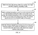
- FIG. 4 a flowchart illustrates a procedure for preheating a write element according to an example embodiment. It is determined 410 (e.g., by a system controller) that data will be written to a portion of a HAMR media. A preheat energizing current is applied 420 to a write element during an interval before writing the data to the portion of the media. The preheat energizing current does not cause data to be written to the media and brings the writer into thermal equilibrium (which is understood to include maintaining an existing thermal equilibrium) prior to writing the data on the portion. After the interval, an energy source (e.g., a laser diode) is energized 430. The energy source is configured to heat the portion of the media and an energizing current is applied to the write element to write data to the heated portion of the media
- an energy source e.g., a laser diode
- HAMR may be used in combination with recording on Bit Patterned Media (BPM).
- BPM formats may include various fields, such as timing recovery and servo fields, embedded within data areas of the media.
- timing fields that are embedded within the data areas of the media are read while on-going write operations are suspended. It may be advantageous to keep writer coil current on when the writer pole traverses these fields to eliminate format overhead associated with the non-zero times it takes to turn write current off and back on during the reading of the timing fields.
- bit patterned media implementations may require precise timing of magnetic field transitions and / or laser pulsing in synchronization with bits on the media.
- the timing of these transitions is affected by electrical delays through the preamp driver circuitry, and these delay times may be affected by the temperature of the circuitry.
- One additional result of early and/or continual application of writer coil current is in bringing the driver circuitry into thermal equilibrium to minimize the timing delay shift.
- writer turn-on/turn-off overhead is reduced by leaving DC write current on while reading the timing fields.
- write transition overhead can be eliminated by writing DC of the same polarity when the writer pole traverses the unipolar field with the laser off or on.
- bipolar-written fields such as runout correction values may be corrupted by a DC write. Therefore, it may be useful in some cases to turn off the laser off when reading the timing fields to prevent overwrite and/or corruption of the data.
- FIG. 5 a flowchart illustrates a process for preheating a write element according to embodiments described herein. It is determined 510 that data will be written to a portion of a HAMR media. A write operation of the data to the heat-assisted magnetic recording media is initiated 520. A write operation is suspended 530 for an interval. According to various implementations, various fields (e.g. timing or servo fields) are read during the interval. A preheat energizing current is applied 540 to a write element, the write element applying a magnetic field to the media in response to the preheat energizing current, and the preheat energizing current not causing data to be written to the media and brings the writer into thermal equilibrium.
- various fields e.g. timing or servo fields
- an energy source e.g. a laser diode
- the write operation is resumed upon completion of the interval and the light source is reenergized. Resuming the write operation may include energizing the light source.
- a cross-sectional diagram shows components of a read/write transducer 600 according to an example embodiment.
- This diagram shows a portion of a slider near a close-point region 601.
- the x-direction is down-track relative to the media
- the z-direction is the cross-track direction.
- a read sensor 602 is located near the ABS 607.
- the read sensor may include a magnetoresistive stack and shielding.
- a reader heater 604 may be implemented to adjust local spacing between the read sensor 602 and a media surface 603.
- a write pole 606 may include a ferromagnetic structure that extends to the ABS 607.
- a write coil 608 is energized to generate a magnetic field within the write pole 606 that extends to the media surface 603.
- the slider may be configured for perpendicular recording, wherein the magnetic orientation is perpendicular (oriented along the y-direction in this view) to the media surface 603. Accordingly, the slider may include one or more return poles 610, 612 that facilitate, along with a particular arrangement of layers in the medium 605, perpendicular orientation of the magnetic fields of the recorded data.
- a spacer 614 may be disposed between the read and write portions of the slider.
- the slider In order to write to the HAMR medium 605, the slider includes a waveguide 616 that extends towards the ABS 607.
- the waveguide 616 delivers light to a near-field transducer (NFT) 618 that is located at the ABS 607 proximate a tip of the write pole 606.
- NFT near-field transducer
- the NFT 618 facilitates directing a beam of electromagnetic energy to the media surface 603 during write operations.
- the energy creates a small hotspot on the media surface 603 with lowered magnetic coercivity, enabling a magnetic field generated from the write pole 606 to affect magnetic orientation within the hotspot.
- the spacer 614 may also include a heater to adjust the head-to-media spacing of the write pole 606 independently from that of the read sensor 602.
- the slider does not include a separate heater.
- the write coil 608 can be activated to provide the heat that might normally be provided by that separate heater. Any magnetic fields generated by this activation of the coil 608 will not change data on the medium 605 so long as the light source is not activated to heat the media surface 603.
- the illustrated example shows a reader heater 604 used with write coil 608 to independently control head-to-media clearances of read and/or write portions of transducer.
- the reader heater 604 controls head-media spacing of the read sensor 602, and the write coil 608, either alone or in combination with the reader heater 604, controls head-media spacing of the write pole 606.
- a different heater e.g., one located proximate write portions of transducer 600
- the write coil 608 is used to adjust head-media spacing of the read sensor 602, assuming the activation of the write coil 608 causes little or no interference with the read sensor 602.
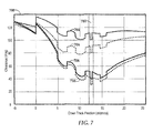
- a graph 700 illustrates an example of ABS protrusions of a HAMR slider according to an example embodiment.
- profiles of the ABS are represented as spacing/clearance between the ABS and media along the vertical axis, and downtrack position along the horizontal axis.
- Downtrack region 702 represents a close point (e.g., near the read or write transducer) of the ABS.
- Trace 704 represents the profile at an ambient temperature where no power is applied to either a heater or write coil.
- Trace 706 is the profile when heater alone is powered; trace 708 represents the profile when heater and write coil are energized; and trace 710 represents the profile when heater, write coil, and laser are all energized.
- the write coil alone may be able to generate enough heat to cause sufficient protrusion.
- the write coil may be used in combination with one or more heaters operating together (instead of a dual heaters operating separately) to achieve desired clearances of both the write and read portions of a magnetic head at different times and/or states of the slider.
- the write coil current can be set to a value that maximizes performance (at a constant head-media spacing) then, in parallel, use a dedicated heater to bring clearance to the desired value. This may be useful during write operations, where write coil activation for writing will cause some predictable amount of protrusion, and the dedicated heater could fine tune the clearances.
- a read/write head may be designed in such a way as to fully take advantage of the writer protrusion as a mechanism for controlling head-media spacing.
- a resistance of a write coil could be increased to induce higher temperatures for purposes of influencing head-media spacing.
- the write coil and/or surrounding areas could be designed with a higher coefficient of thermal expansion to increase protrusion.
- features designed to cool the write coil could be designed in such a way as to decrease cooling at the coil and proximate areas, e.g., using materials of lower thermal conductivity.
- a flowchart illustrates a procedure according to an example embodiment.
- a first path 802 is taken if a heat-assisted magnetic recording media is not being written to.
- heat from a write head to the recording media is removed 804. This may involve turning off or disengaging a device (e.g., laser, optical pathway) that provides the heat.
- Power is applied 806 to write coil of the write head to control a spacing between the write head and the recording media when the media is not being written to. This may include spacing between a read and/or write element of the write head.
- power may be applied 807 to a dedicated heater to control the spacing in parallel with the application 806 of power to the write coil.
- Path 808 represents head-to-disk clearance operations that occur when the recording media is being written to, where at least a source of heat (e.g., laser light) is applied to the recording media. Heat is applied 810 from the write head to the recording media 810. One or both of operations 812 and 814 may be performed to adjust a clearance (e.g., clearance between media and read head and/or write pole) while the media is being written to. Operation 812 involves applying power to the write coil to both record data and to control spacing between the write head and the media. Operation 814 involves applying power to a dedicated heater to control the spacing between the write head and the media. This may be the same dedicated heater used at block 807.
- a source of heat e.g., laser light
- An apparatus includes: a write element configured to magnetize a portion of a heat-assisted magnetic recording medium in response to an energizing current during a write operation; an energy source configured to heat the portion of the medium being magnetized by the write element; and wherein the energizing current is applied to the write element during an interval during which the write operation is suspended and the energy source is de-energized, wherein applying the energizing current to the write element does not cause other data to be written to the medium and the energizing current brings the write element and/or driver circuitry into thermal equilibrium prior to writing the data on the portion.
- the energy source may include a laser diode.
- the write operation may be resumed upon completion of the interval. Resuming the write operation may involve energizing the energy source.
- the apparatus may be configured to read timing fields during the interval.
Landscapes
- Physics & Mathematics (AREA)
- Electromagnetism (AREA)
- Engineering & Computer Science (AREA)
- Manufacturing & Machinery (AREA)
- Recording Or Reproducing By Magnetic Means (AREA)
- Magnetic Heads (AREA)
Abstract
Description
- This is a continuation-in-part of
U.S. Patent Application 13/687,282 filed on November 28, 2012 61/676,835 filed on July 27, 2012 - Examples described herein are directed to a heat-assisted magnetic recording device. In one embodiment, an apparatus includes a write element configured to apply a magnetic field to write data on a portion of a heat-assisted magnetic recording media in response to an energizing current. An energy source is configured to heat the portion of the media being magnetized by the write element. A preheat energizing current is applied to the write element during an interval before writing the data to the portion of the media. The preheat energizing current does not cause data to be written to the media and brings at least one of the write element and driver circuitry into thermal equilibrium prior to writing the data on the portion.
- In another embodiment, methods and apparatuses facilitate determining that data will be written to a portion of a heat-assisted magnetic recording medium. A preheat energizing current is applied to a write element during an interval before writing the data to the portion of the medium. The write element applies a magnetic field to the medium in response to the preheat energizing current. The preheat energizing current does not cause other data to be written to the medium and brings at least one of the write element and driver circuitry into thermal equilibrium prior to writing the data on the portion. After the interval, an energy source configured to heat the portion of the medium energized and an energizing current is applied to the write element to write data to the portion of the medium.
- In another embodiment, while a heat-assisted, magnetic recording media is not being written to, heat applied from a write head to the recording media is removed. The heat facilitates writing to the recording media. Power is applied to a write coil of the write head to control spacing between the write head and the recording media when the recording media is not being written.
- These and other features and aspects of various embodiments may be understood in view of the following detailed discussion and accompanying drawings.
- The discussion below makes reference to the following figures, wherein the same reference number may be used to identify the similar/same component in multiple figures.
-
FIG. 1 is a side view of a slider according to an example embodiment; -
FIG. 2 is a timing diagram illustrating pre-heating of a slider according to example embodiments; -
FIG. 3 is a block diagram of an apparatus according to an example embodiment; -
FIG. 4 is a flowchart illustrating a procedure according to an example embodiment; -
FIG. 5 is a flowchart illustrating a process according to various embodiments; -
FIG. 6 is a cross-sectional view of a write head according to an example embodiment; -
FIG. 7 is a graph illustrating write coil induced protrusion according to an example embodiment; and -
FIG. 8 is a flowchart illustrating a procedure according to an example embodiment. - This disclosure is related to the use of preheating a write element (e.g., a write coil) and related circuitry in order to achieve thermal equilibrium in a heat-assisted magnetic recording (HAMR) device. In one embodiment, the writer coil and driver circuitry preheating is controlled externally, e.g., via a system controller. The same outcome can also be realized in the preamp via firmware-controlled registers affecting internal preamp circuits. Other permutations of control are also possible. Writer coil current is applied in advance of the actual write operation, thereby simplifying the control of fly-height for writer protrusion during an active write operation.
- In HAMR devices, also sometimes referred to as thermal-assisted magnetic recording (TAMR) devices, heat energy is used in conjunction with magnetic fields applied to a magnetic recording media (e.g., a hard drive disk) to overcome superparamagnetic effects that limit the areal data density of traditional magnetic media. In a HAMR recording device, information bits are recorded on a storage layer at elevated temperatures. The heated area in the storage layer determines the data bit dimension, and linear recording density is determined by the magnetic transitions between the data bits.
- In order to achieve desired data density, a HAMR recording head (e.g., slider) includes optical components that direct, concentrate, and transform light energy from an energy source, such as a laser diode, to heat on the recording media. The HAMR media hotspot may need to be smaller than a half-wavelength of light available from economical sources (e.g., laser diodes). Due to what is known as the diffraction limit, optical components cannot focus the light at this scale. One way to achieve tiny confined hot spots is to use an optical near-field transducer (NFT), such as a plasmonic optical antenna. The NFT is designed to have a surface plasmon resonance at the designed light wavelength. At resonance, a high electric field surrounds the NFT due to the collective oscillation of electrons in the metal. Part of the field tunnels into the storage medium and is absorbed, raising the temperature of the medium locally above the Curie point for recording. Without the presence of the heat energy, the media will be below the Curie point, and no effective erasure or re-magnetization will occur, even if the magnetic field from the writer is present. However, it is implicitly understood that the magnetic transitions are defined (magnetically frozen) at temperatures less than the Curie temperature.
- A HAMR drive may use a laser and a near field transducer to heat the media to aid in the recording process. Due to inefficiencies of the optical transmission path, the laser and near field transducer also heat the head/slider. The heating can originate from the NFT, the light delivery optics and/or from the laser itself. Energy absorbed in these components may be converted to heat, which is conducted to the surrounding materials. This heating can lead to head-media spacing (HMS) changes by causing the writer element to protrude (i.e. fly closer to the disk) through slider thermal expansion or by changing the shape of the slider and changing the air bearing characteristics. An example of this is shown in
FIG. 1 , which illustrates a side view of aslider 102 according to an example embodiment. - For controlling the laser in some HAMR drive embodiments, a technique known as pulsing is used. Pulsing flashes the laser in synchronization with magnetic transitions from the writer coil. The timing of the pulsing with respect to the transitions can affect the bit error rate of the recording system. The timing of these transitions is affected by electrical delays through the preamp driver circuitry, and these delay times may be affected by the temperature of the circuitry. One additional result of early and/or continual application of writer coil current is in bringing the driver circuitry into thermal equilibrium to minimize the timing delay shift.
- The
slider 102 is coupled to an arm (not shown) by way of asuspension 104, attached to agimbal 106 that allows some relative motion between theslider 102 andsuspension 104. Theslider 102 includes read/writetransducers 108 at a trailing edge that are held proximate to a surface 110 of a magnetic recording medium, e.g.,disk 111. When theslider 102 is located over surface 110 ofdisk 111, aflying height 112 is maintained between theslider 102 and the surface 110 by a downward force of thesuspension 104. This downward force is counterbalanced by an air cushion that exists between the surface 110 and an air bearing surface (ABS) 103 of theslider 102 when thedisk 111 is rotating. - It is desirable to maintain a predetermined spacing between writer and reader elements and the
media 112 over a range of cylindrical disk positions during both reading and writing operations to ensure consistent performance. Aregion 114 is a "close point" of theslider 102, which is generally understood to be the closest point of contact between theslider 102 and themagnetic recording medium 111, and generally defines the HMS 113. Heating from HAMR optical components can affect the HMS 113. - Heating from the writer coil current can affect the HMS 113. In this example, the geometry change may be induced, in whole or in part, by an increase or decrease in temperature of the
region 114 due to different thermal expansion properties of the respective materials surrounding the region. This is shown inFIG. 1 by dotted line that represents a change in geometry of theregion 114. Example HAMR components that may induce these temperature changes include a top mountedlaser 119,waveguide 121, andNFT 123. To control spacing, many recording heads additionally include one or more internal heaters (not shown) to deliberately add heat. In one exemplary embodiment, theslider 102 contains two heaters. The first additional heater is in close proximity to the reader element and is referred to as the reader-heater. The second heater is in close proximity to the writer element and is referred to as the writer-heater. - The
slider 102 may include aresistive temperature sensor 120 located at or proximate toregion 114. Thissensor 120 has a temperature coefficient of resistance (TCR) that enables high precision measurements of temperature (or temperature change) at theregion 114, and so is sometimes referred to as a TCR sensor. TheTCR sensor 120 is coupled to controlcircuitry 122. Thecontrol circuitry 122 communicates with thesensor 120, as well as other electrical components of theslider 102. Two ormore TCR sensors 120 may be employed, e.g., disposed in physically separate locations from each other.Multiple sensors 120 be wired separately from each other, or together (e.g., in series or parallel) to reduce the number of connections needed for theslider 102. - With a HAMR recording device, four protrusions may need to be managed at the ABS during write, each with different time constants: writer-heater protrusion (∼100 µs); writer coil protrusion (∼100 µs); NFT protrusion (∼1 µs followed bey ∼ 100 µs); and laser heating of slider (∼1000 µs). Conventional HAMR preamps turn on the writer coil simultaneously with the laser. This results in an interaction between the writer-coil and the NFT induced protrusions. Due to the high coercivity of HAMR media the head cannot write to the media unless the laser is active. This means writer-coil and writer-heater currents can be enabled prior to writing, which allows them to reach thermal equilibrium by the time writing occurs. This means only thermal protrusion dynamics from the laser need be considered since everything else is in thermal equilibrium.
- Accordingly, a preamp according to an example embodiment may be modified to apply a current through the writer in advance of sector(s) being written. In such a configuration, the writer coil current can either be kept on or turned off during sector gaps and servo gates (SG), so long as the laser is off during those times. It may be preferable to turn off the writer current during SG to avoid coupling into the read head and affecting the servo system.
- The pre-heat current applied to the writer coil can be alternating current (AC) or direct current (DC). An AC signal may avoid any pitfalls with DC magnetic fields, although a DC signal may be required if the writer-coil current is left on during SG in order to reduce electrical noise. For example,
U.S. Patent 7,088,537 by Cronch et al describes a degauss mode in a disk drive preamp. The degauss mode circuitry in the preamp (or similar) can be used as a control source for the AC current for this purpose. The AC signal can either be internally generated within the preamp and/or externally generated by the system read channel (SRC), which is part of the system controller, e.g., the hard-drive's main controller application-specific integrated circuit (ASIC). Either approach is acceptable and both are shown here. - In reference now to
FIG. 2 a timing diagram shows an example of how a recording head may be preheated according to an example embodiment. The diagram is divided into four types of signals:timing control 202, laser andchannel writer control 204,firmware control 206, andphysical currents 208. - As illustrated by
trace 216, the firmware writes preamp registers to set the current for laser bias and the writer coil in advance of the write operation, attime 201. The firmware enables preheating with enough time for the writer-heater current 238 and writer-coil current 228 to cause their affected components to reach thermal equilibrium. The preheating time for the writer-coil is indicated inFIG. 2 by interval 203. - The firmware can optionally enable a new preamp feature that sends current to writer coils using an internally generated AC or DC signal. An example of this is seen in
FIG. 3 , which is a block diagram of anapparatus 300 according to an example embodiment. Theapparatus 300 includes asystem controller 317 that may include one or more logic circuits that control functions of theapparatus 300. Thesystem controller 317 receives commands via ahost interface 303. In response to write commands from thehost interface 303, thesystem controller 317 causes awrite preamplifier assembly 301 to write data to a magneticdata storage medium 305. - The
preamplifier assembly 301 includes writer-coil driver circuitry 302 that drives one or more write coils 304 contained withinrecording head 318. Thewrite coil 304 creates a magnetic field in response to a current being applied. Thepreamp 301 is controlled by combining, viamultiplexer 306, write enableline 308, and write data signals (WDATA+/-) 309, 310 amongst other control signals not shown. The apparatus includesfirmware 315 that, in conjunction with thesystem controller 317, enables thepreamplifier assembly 301 to send current to thewriter coil 304 using an internally generated AC or DC signal The AC signal may be generated by aninternal oscillator 320, such as what is used for degaussing operations. This alleviates the necessity to control the write data signal (WDATA+/-) 309, 310 to perform the preheat signaling. The writer-coil preheating may be turned off during servo (e.g., duringperiod 205 inFIG. 2 ) to minimize cross talk between the writer and reader lines on the flex on suspension (FOS). - The
apparatus 300 further includes an energy source 316 (e.g., a concentrated laser diode output) that heats a portion of the medium 305 currently being magnetized by thewrite coil 304. Theenergy source 316 is enabled via the system controller 317 (e.g., via laser enableline 224 inFIG. 2 ) to heat a portion of the medium 305 during recording. For purposes of this discussion, the "portion of the medium" may include a region larger than a signal bit of data being written. For example, the portion may include multiple hard drive sectors, and writing may be suspended and resumed during writing of the portion, e.g., when traversing servo marks. - As described herein, activation of the
write coil 304 when theenergy source 316 is not energized will generally not cause other data to be written to the medium 305 (e.g., no significant change in local magnetic orientation at the medium) nor any existing data to be obliterated. It is noteworthy that, in some designs utilizing a semiconductor laser diode as an energy source, it is desirable to still have a small current flowing through the laser diode while not writing. For purposes of this disclosure, the laser can still be thought of as being de-energized even when a small bias current is present, so long as the laser is not sufficiently lasing to raise the media temperature near or above its Curie point. As such, in some cases thewrite coil 304 may be activated by an energizing current to bring a write element (e.g., thewrite coil 304, write pole, and associated components) into thermal equilibrium without writing other data to the medium 305 while activated. In order to achieve this, theenergy source 316 and writecoil 304 may be controlled via separate signals. - In reference again to
FIG. 2 , signals 214, 224, and 234 are generally considered part of the system controller's read channel's writer and laser controls. The channel controls a writer-enable (W/Rn) line (signal 234), as well as the write data lines (signal 214) and the laser enable line (signal 224). The channel enables the laser whenever it wants to write data to the disk. The laser enable line is not the same as W/Rn since it may be needed to keep from writing consecutive sectors when such writing is not needed. Separating these lines also allows for pulsing control and the ability for writer pre-heat. In continuous writing mode the laser control is a logic signal. For pulsed recording the logic gate may be replaced by high-bandwidth laser data. -
Signals - In
FIG. 4 , a flowchart illustrates a procedure for preheating a write element according to an example embodiment. It is determined 410 (e.g., by a system controller) that data will be written to a portion of a HAMR media. A preheat energizing current is applied 420 to a write element during an interval before writing the data to the portion of the media. The preheat energizing current does not cause data to be written to the media and brings the writer into thermal equilibrium (which is understood to include maintaining an existing thermal equilibrium) prior to writing the data on the portion. After the interval, an energy source (e.g., a laser diode) is energized 430. The energy source is configured to heat the portion of the media and an energizing current is applied to the write element to write data to the heated portion of the media - According to various implementations, HAMR may be used in combination with recording on Bit Patterned Media (BPM). BPM formats may include various fields, such as timing recovery and servo fields, embedded within data areas of the media. According to various implementations, timing fields that are embedded within the data areas of the media are read while on-going write operations are suspended. It may be advantageous to keep writer coil current on when the writer pole traverses these fields to eliminate format overhead associated with the non-zero times it takes to turn write current off and back on during the reading of the timing fields.
- Additionally, bit patterned media implementations may require precise timing of magnetic field transitions and / or laser pulsing in synchronization with bits on the media. The timing of these transitions is affected by electrical delays through the preamp driver circuitry, and these delay times may be affected by the temperature of the circuitry. One additional result of early and/or continual application of writer coil current is in bringing the driver circuitry into thermal equilibrium to minimize the timing delay shift.
- According to various implementations, writer turn-on/turn-off overhead is reduced by leaving DC write current on while reading the timing fields. For example, when timing fields are patterned such that unipolar magnetization can be used, write transition overhead can be eliminated by writing DC of the same polarity when the writer pole traverses the unipolar field with the laser off or on. However, in some cases, bipolar-written fields such as runout correction values may be corrupted by a DC write. Therefore, it may be useful in some cases to turn off the laser off when reading the timing fields to prevent overwrite and/or corruption of the data.
- It may be useful to eliminate writer turn-on/turn-off overhead and achieve faster thermal equilibrium by leaving DC write current and laser on while over unipolar BPM servo fields. However, in some cases, within or abutting these servo fields, there may be bipolar-written information fields (such as runout correction values) that would be corrupted by a DC write. Thus it would be advantageous in a HAMR + BPM system to turn off the laser during unipolar fields to enable leaving write current on without risk of corrupting bipolar information fields.
- In
FIG. 5 , a flowchart illustrates a process for preheating a write element according to embodiments described herein. It is determined 510 that data will be written to a portion of a HAMR media. A write operation of the data to the heat-assisted magnetic recording media is initiated 520. A write operation is suspended 530 for an interval. According to various implementations, various fields (e.g. timing or servo fields) are read during the interval. A preheat energizing current is applied 540 to a write element, the write element applying a magnetic field to the media in response to the preheat energizing current, and the preheat energizing current not causing data to be written to the media and brings the writer into thermal equilibrium. After the interval, an energy source (e.g. a laser diode) is energized 550. In some cases, the write operation is resumed upon completion of the interval and the light source is reenergized. Resuming the write operation may include energizing the light source. - In reference now to
FIG. 6 , a cross-sectional diagram shows components of a read/write transducer 600 according to an example embodiment. This diagram shows a portion of a slider near a close-point region 601. In this view, the x-direction is down-track relative to the media, and the z-direction (normal to the plane of the page) is the cross-track direction. Aread sensor 602 is located near theABS 607. The read sensor may include a magnetoresistive stack and shielding. Areader heater 604 may be implemented to adjust local spacing between the readsensor 602 and amedia surface 603. - A
write pole 606 may include a ferromagnetic structure that extends to theABS 607. Awrite coil 608 is energized to generate a magnetic field within thewrite pole 606 that extends to themedia surface 603. The slider may be configured for perpendicular recording, wherein the magnetic orientation is perpendicular (oriented along the y-direction in this view) to themedia surface 603. Accordingly, the slider may include one ormore return poles spacer 614 may be disposed between the read and write portions of the slider. - In order to write to the
HAMR medium 605, the slider includes awaveguide 616 that extends towards theABS 607. Thewaveguide 616 delivers light to a near-field transducer (NFT) 618 that is located at theABS 607 proximate a tip of thewrite pole 606. TheNFT 618 facilitates directing a beam of electromagnetic energy to themedia surface 603 during write operations. The energy creates a small hotspot on themedia surface 603 with lowered magnetic coercivity, enabling a magnetic field generated from thewrite pole 606 to affect magnetic orientation within the hotspot. - In some configurations, the spacer 614 (or some other region proximate the
write pole 606 and/or returnpoles 610, 612) may also include a heater to adjust the head-to-media spacing of thewrite pole 606 independently from that of theread sensor 602. However, in this example, the slider does not include a separate heater. Instead, thewrite coil 608 can be activated to provide the heat that might normally be provided by that separate heater. Any magnetic fields generated by this activation of thecoil 608 will not change data on the medium 605 so long as the light source is not activated to heat themedia surface 603. - The illustrated example shows a
reader heater 604 used withwrite coil 608 to independently control head-to-media clearances of read and/or write portions of transducer. In one example, thereader heater 604 controls head-media spacing of theread sensor 602, and thewrite coil 608, either alone or in combination with thereader heater 604, controls head-media spacing of thewrite pole 606. In another example, a different heater (e.g., one located proximate write portions of transducer 600) may be used to control head-media spacing of thewrite pole 606, and the write coil 608 (either alone or together with the different heater) is used to adjust head-media spacing of theread sensor 602, assuming the activation of thewrite coil 608 causes little or no interference with theread sensor 602. - In reference now to
FIG. 7 , agraph 700 illustrates an example of ABS protrusions of a HAMR slider according to an example embodiment. In thisgraph 700, profiles of the ABS are represented as spacing/clearance between the ABS and media along the vertical axis, and downtrack position along the horizontal axis.Downtrack region 702 represents a close point (e.g., near the read or write transducer) of the ABS.Trace 704 represents the profile at an ambient temperature where no power is applied to either a heater or write coil.Trace 706 is the profile when heater alone is powered;trace 708 represents the profile when heater and write coil are energized; andtrace 710 represents the profile when heater, write coil, and laser are all energized. - As the difference between
traces - Various features of a read/write head may be designed in such a way as to fully take advantage of the writer protrusion as a mechanism for controlling head-media spacing. For example, a resistance of a write coil could be increased to induce higher temperatures for purposes of influencing head-media spacing. The write coil and/or surrounding areas could be designed with a higher coefficient of thermal expansion to increase protrusion. In another example, features designed to cool the write coil could be designed in such a way as to decrease cooling at the coil and proximate areas, e.g., using materials of lower thermal conductivity.
- In reference now to
FIG. 8 , a flowchart illustrates a procedure according to an example embodiment. In this procedure, afirst path 802 is taken if a heat-assisted magnetic recording media is not being written to. In such a case, heat from a write head to the recording media is removed 804. This may involve turning off or disengaging a device (e.g., laser, optical pathway) that provides the heat. Power is applied 806 to write coil of the write head to control a spacing between the write head and the recording media when the media is not being written to. This may include spacing between a read and/or write element of the write head. Optionally, power may be applied 807 to a dedicated heater to control the spacing in parallel with theapplication 806 of power to the write coil. -
Path 808 represents head-to-disk clearance operations that occur when the recording media is being written to, where at least a source of heat (e.g., laser light) is applied to the recording media. Heat is applied 810 from the write head to therecording media 810. One or both ofoperations Operation 812 involves applying power to the write coil to both record data and to control spacing between the write head and the media.Operation 814 involves applying power to a dedicated heater to control the spacing between the write head and the media. This may be the same dedicated heater used atblock 807. - An apparatus includes: a write element configured to magnetize a portion of a heat-assisted magnetic recording medium in response to an energizing current during a write operation; an energy source configured to heat the portion of the medium being magnetized by the write element; and wherein the energizing current is applied to the write element during an interval during which the write operation is suspended and the energy source is de-energized, wherein applying the energizing current to the write element does not cause other data to be written to the medium and the energizing current brings the write element and/or driver circuitry into thermal equilibrium prior to writing the data on the portion.. The energy source may include a laser diode. The write operation may be resumed upon completion of the interval. Resuming the write operation may involve energizing the energy source. The apparatus may be configured to read timing fields during the interval.
- The foregoing description of the example embodiments has been presented for the purposes of illustration and description. It is not intended to be exhaustive or to limit the embodiments to the precise form disclosed. Many modifications and variations are possible in light of the above teaching. Any or all features of the disclosed embodiments can be applied individually or in any combination are not meant to be limiting, but purely illustrative. It is intended that the scope of the invention be limited not with this detailed description, but rather determined by the claims appended hereto.
Claims (20)
- An apparatus (300) comprising:a write element (304) configured to apply a magnetic field to write data on a portion of a heat-assisted magnetic recording medium (305) in response to an energizing current;an energy source (316) configured to heat the portion of the medium being magnetized by the write element; andwherein a preheat energizing current is applied to the write element during an interval before writing the data to the portion of the medium, wherein the preheat energizing current does not cause other data to be written to the medium and brings at least one of the write element and driver circuitry into thermal equilibrium prior to writing the data to the portion.
- The apparatus of claim 1, wherein the energy source comprises a laser diode, and wherein the energy source is not energized during the interval.
- The apparatus of claim 1 or claim 2, wherein the preheat energizing current comprises an alternating current.
- The apparatus of claim 3, wherein the alternating current is controlled by a system controller (317).
- The apparatus of claim 3, wherein the alternating current is controlled by a preamp (301) that drives the write element.
- The apparatus of claim 1 or claim 2, wherein the preheat energizing current comprises a direct current.
- The apparatus of any one of the preceding claims, wherein the medium comprises a bit patterned medium.
- The apparatus of claim 7, wherein a unipolar field is traversed during the interval, wherein the energizing current is a direct current, and wherein the energy source is energized during the interval.
- The apparatus of claim 7, wherein a bipolar field is traversed during the interval, and wherein the energy source is not energized during the interval.
- A method comprising:(410) determining that data will be written to a portion of a heat-assisted magnetic recording medium (305);(420) applying a preheat energizing current to a write element (304) during an interval before writing the data to the portion of the medium, wherein the preheat energizing current does not cause other data to be written to the medium and brings the write element and/or driver circuitry into thermal equilibrium prior to writing the data on the portion;(430) after the interval, energizing an energy source (316) configured to heat the portion of the medium and applying an energizing current to the write element to write the data to the portion of the medium.
- The method of claim 10, further comprising de-energizing the energy source during the interval.
- The method of claim 10 or claim 11, wherein the preheat energizing current comprises an alternating current.
- The method of claim 12, further comprising controlling the alternating current via a system controller (317).
- The method of claim 12, further comprising controlling the alternating current within a preamp (301) that drives the write element.
- A write head (600), comprising:a device (616, 618) configured to apply heat to a heat-assisted magnetic recording media (605) to facilitate writing to the recording media;a write coil (608) configured to apply a magnetic field to the magnetic media in response to application of power to the write coil, wherein the write coil is configured to control, at least when the heat is removed from the recording media, a spacing between the write head and the magnetic media in response to the application of power to the write coil.
- The write head of claim 15, wherein the device comprises a near-field transducer (618), the apparatus further comprising an optical device (616) configured to apply energy to the near-field transducer.
- The write head of claim 15 or claim 16, wherein the application of power to the write coil causes a heat-induced protrusion of the write head that varies the spacing between the write head and the recording media.
- The write head of any one of claims 15 to 17, wherein the application of the power to the write coil is employed in place of a heater dedicated to control the spacing for a transducer of the write head.
- The write head of any one of claims 15 18, wherein the write coil is further configured to both record data to the magnetic media and to control the spacing between the write head and the recording media during writing to the recording media.
- The write head of any one of claims 15 to 19, wherein the magnetic field does not write data to the recording media when the heat is removed from the recording media.
Applications Claiming Priority (3)
| Application Number | Priority Date | Filing Date | Title |
|---|---|---|---|
| US201261676835P | 2012-07-27 | 2012-07-27 | |
| US13/687,282 US8867323B2 (en) | 2012-11-28 | 2012-11-28 | Controlling head-media spacing using a write coil |
| US13/831,129 US9019646B2 (en) | 2012-07-27 | 2013-03-14 | Heat assisted magnetic recording device with pre-heated write element |
Publications (2)
| Publication Number | Publication Date |
|---|---|
| EP2690624A1 true EP2690624A1 (en) | 2014-01-29 |
| EP2690624B1 EP2690624B1 (en) | 2017-04-12 |
Family
ID=48875590
Family Applications (1)
| Application Number | Title | Priority Date | Filing Date |
|---|---|---|---|
| EP13178288.0A Not-in-force EP2690624B1 (en) | 2012-07-27 | 2013-07-26 | Heat assisted magnetic recording device with pre-heated write element |
Country Status (2)
| Country | Link |
|---|---|
| US (1) | US9019646B2 (en) |
| EP (1) | EP2690624B1 (en) |
Cited By (1)
| Publication number | Priority date | Publication date | Assignee | Title |
|---|---|---|---|---|
| GB2512469A (en) * | 2013-02-26 | 2014-10-01 | HGST Netherlands BV | Method for controlling writing in a thermally-assisted recording(tar) disk drive with thermal fly-height control |
Families Citing this family (36)
| Publication number | Priority date | Publication date | Assignee | Title |
|---|---|---|---|---|
| US8897104B1 (en) * | 2013-04-02 | 2014-11-25 | Western Digital (Fremont), Llc | Method and system for performing off-disk measurements of laser-induced NFT protrusion in a heat assisted magnetic recording transducer |
| US9042210B2 (en) | 2013-09-26 | 2015-05-26 | Seagate Technology Llc | Multi-purpose near-field transducer having a temperature coefficient of resistance |
| US9153266B1 (en) | 2014-09-11 | 2015-10-06 | Western Digital Technologies, Inc. | Data storage device measuring laser protrusion fly height profile |
| US9905996B2 (en) | 2014-09-22 | 2018-02-27 | Seagate Technology Llc | Heat assisted media recording device with reduced likelihood of laser mode hopping |
| US9281659B1 (en) | 2014-09-22 | 2016-03-08 | Seagate Technology Llc | Thermal management of laser diode mode hopping for heat assisted media recording |
| US10163456B2 (en) | 2014-11-11 | 2018-12-25 | Seagate Technology Llc | Near-field transducer with recessed region |
| US9548072B2 (en) | 2015-02-11 | 2017-01-17 | Seagate Technology Llc | Concurrent modulation and frictional heating head disk contact detection |
| US9472225B2 (en) * | 2015-02-11 | 2016-10-18 | Seagate Technology Llc | Heat-assisted magnetic recording head-disk clearance setting |
| US9245541B1 (en) * | 2015-04-30 | 2016-01-26 | Seagate Technology Llc | Storage device with adaptive voltage generation system |
| US9626989B1 (en) * | 2015-09-22 | 2017-04-18 | Seagate Technology Llc | Selective powering techniques for heat assisted magnetic recording |
| US9460745B1 (en) | 2015-09-29 | 2016-10-04 | HGST Netherlands B.V. | Preheating a hard disk drive head slider for head switch seek |
| US9978405B1 (en) * | 2016-03-02 | 2018-05-22 | Seagate Technology Llc | Heat assisted magnetic recording slider having a consistent close point |
| US9620162B1 (en) | 2016-03-31 | 2017-04-11 | Western Digital Technologies, Inc. | Data storage device boosting prelase bias while over data sector for heat assisted magnetic recording |
| US9607649B1 (en) * | 2016-04-08 | 2017-03-28 | Seagate Technology Llc | Determining write-induced protrusion as a function of laser power using temperature measurements |
| US9734862B1 (en) | 2016-10-17 | 2017-08-15 | Seagate Technology Llc | Method and apparatus for writing test tracks on a magnetic recording medium |
| US10152997B1 (en) | 2017-06-12 | 2018-12-11 | Seagate Technology Llc | Laser current calibration using preamplifier |
| US9990950B1 (en) | 2017-07-17 | 2018-06-05 | Seagate Technology Llc | Calibration and adjusting target pre-write clearance offset for a heat-assisted magnetic recording device |
| US10490215B1 (en) | 2017-08-04 | 2019-11-26 | Seagate Technology Llc | Near-field transducer dielectric wrap for reducing heat |
| US10366719B1 (en) | 2018-03-20 | 2019-07-30 | Seagate Technology Llc | Boosted preheat trajectory to obtain desired clearance before writing to disk |
| US10360935B1 (en) | 2018-05-22 | 2019-07-23 | Headway Technologies, Inc. | Dual write heater for slider surface topography control in double perpendicular magnetic recording (PMR) writers |
| US11020816B1 (en) | 2018-09-05 | 2021-06-01 | Seagate Technology Llc | Methods of forming a friction stir weld between a steel piece and an aluminum piece, and related assemblies |
| US11869548B1 (en) | 2020-10-29 | 2024-01-09 | Western Digital Technologies, Inc. | Magnetic recording devices having external alternating current sources |
| US11694712B2 (en) | 2021-04-27 | 2023-07-04 | Western Digital Technologies, Inc. | Data storage device pre-biasing write current for energy assisted magnetic recording |
| US11404079B1 (en) | 2021-04-27 | 2022-08-02 | Western Digital Technologies, Inc. | Data storage device writing to defective data sector for fly height control |
| US11475912B1 (en) | 2021-06-11 | 2022-10-18 | Seagate Technology Llc | Synchronous writing of patterned media |
| US11631431B2 (en) | 2021-07-02 | 2023-04-18 | Seagate Technology Llc | Analog optical link for a moveable actuator in a data storage system |
| US11881237B1 (en) | 2021-11-24 | 2024-01-23 | Western Digital Technologies, Inc. | Cross track current design for energy assisted magnetic recording |
| US11894026B1 (en) | 2022-06-21 | 2024-02-06 | Western Digital Technologies, Inc. | Magnetic recording head having leads over the trailing shield for assisting electric currents |
| US11900971B1 (en) | 2022-06-21 | 2024-02-13 | Western Digital Technologies, Inc. | Magnetic recording head with assisting electric current in trailing shield |
| US12159652B2 (en) | 2022-12-28 | 2024-12-03 | Western Digital Technologies, Inc. | Energy-assisted magnetic recording data storage device with opportunistic boosted laser pre-biasing |
| US12046266B1 (en) | 2023-06-23 | 2024-07-23 | Western Digital Technologies, Inc. | Energy-assisted magnetic recording data storage device with assistive energy pre-heating for writing servo patterns |
| US12125509B1 (en) * | 2023-10-10 | 2024-10-22 | Western Digital Technologies, Inc. | Dark laser heating by positive pulse biasing in heat assisted magnetic recording |
| US12176015B1 (en) | 2023-10-19 | 2024-12-24 | Western Digital Technologies, Inc. | Pole tip recession compensation by dual heater ratio optimization in a hard disk drive |
| US12347466B1 (en) | 2024-02-21 | 2025-07-01 | Western Digital Technologies, Inc. | Data storage device with command selection that minimizes frequency of pre-heating |
| US12223983B1 (en) | 2024-02-24 | 2025-02-11 | Western Digital Technologies, Inc. | Data storage device with write caching for maximizing disk access during laser diode steady state |
| US12300285B1 (en) | 2024-06-13 | 2025-05-13 | Western Digital Technologies, Inc. | Measuring NFT protrusion in a heat assisted magnetic recording drive using burst writing and a constant laser diode temperature |
Citations (5)
| Publication number | Priority date | Publication date | Assignee | Title |
|---|---|---|---|---|
| US20040252396A1 (en) * | 2003-06-16 | 2004-12-16 | Seagate Technology Llc | Method and apparatus for mitigating thermal pole tip protrusion |
| US7088537B2 (en) | 2004-03-09 | 2006-08-08 | Seagate Technology Llc | Removing residual magnetization in a data transducer |
| US20080068739A1 (en) * | 2006-09-14 | 2008-03-20 | Fujitsu Limited | Storage apparatus, control method, and control circuit |
| US7388726B1 (en) * | 2002-08-02 | 2008-06-17 | Seagate Technology Llc | Dynamically adjustable head disk spacing slider using thermal expansion |
| US20100232050A1 (en) * | 2009-03-11 | 2010-09-16 | Headway Technologies, Inc. | Power control of TAMR element during read/write transition |
Family Cites Families (27)
| Publication number | Priority date | Publication date | Assignee | Title |
|---|---|---|---|---|
| US7119990B2 (en) | 2002-05-30 | 2006-10-10 | Komag, Inc. | Storage device including a center tapped write transducer |
| KR100532411B1 (en) | 2002-06-22 | 2005-12-02 | 삼성전자주식회사 | Method and apparatus for controlling a data storage system according to temperature |
| US7006336B2 (en) | 2002-08-06 | 2006-02-28 | International Business Machines Corporation | Magnetic head having a heater circuit for thermally-assisted writing |
| JP2004355739A (en) | 2003-05-29 | 2004-12-16 | Toshiba Corp | Magnetic recording device |
| US7212381B2 (en) | 2003-08-14 | 2007-05-01 | Seagate Technology Llc | Slider having adjusted transducer recession and method of adjusting recession |
| US6975472B2 (en) | 2003-09-12 | 2005-12-13 | Seagate Technology Llc | Head with heating element and control regime therefor |
| US7589936B1 (en) | 2003-12-04 | 2009-09-15 | Seagate Technology Llc | Center-tapped write coil |
| US7660080B1 (en) | 2004-04-30 | 2010-02-09 | Western Digital (Fremont), Llc | Read/write head with dynamic flying height control by magnetostriction |
| US7092195B1 (en) | 2004-05-28 | 2006-08-15 | Western Digital (Fremont), Inc. | Method of using a magnetic write head having an internal heater |
| JP4317118B2 (en) | 2004-11-26 | 2009-08-19 | 富士通株式会社 | Thermally assisted magnetic recording method |
| US7190543B2 (en) | 2005-01-31 | 2007-03-13 | Hitachi Global Storage Technologies Netherlands B.V. | Method and apparatus for optimizing flying height control using heated sliders |
| WO2006100718A1 (en) | 2005-03-18 | 2006-09-28 | Fujitsu Limited | Storage device, storage medium, and storage device control method and program |
| US7375912B2 (en) | 2005-05-31 | 2008-05-20 | Texas Instruments Incorporated | Disk drive fly height control based on constant power dissipation in read/write head heaters |
| US7215495B1 (en) | 2005-12-27 | 2007-05-08 | Hitachi Global Storage Technologies Netherlands B.V. | System and method for determining head-disk contact in a magnetic recording disk drive |
| JP2008027504A (en) | 2006-07-20 | 2008-02-07 | Fujitsu Ltd | Magnetic head |
| US7457072B2 (en) | 2006-12-04 | 2008-11-25 | Hitachi Global Storage Technologies Netherlands B.V. | Disk drive with head fly-height compensation for disk surface variations |
| US7375914B1 (en) | 2007-02-27 | 2008-05-20 | Hitachi Global Storage Technologies Netherlands B.V. | Disk drive with improved method for operating a thermal head fly-height actuator |
| US7538961B2 (en) | 2007-06-20 | 2009-05-26 | Hitachi Global Storage Technologies Netherlands B.V. | Using inductance to measure writer spacing in perpendicular magnetic recording |
| US8164987B2 (en) | 2008-10-29 | 2012-04-24 | Hitachi Global Storage Technologies Netherlands B.V. | Thermally assisted magnetic head |
| US7889450B2 (en) | 2008-11-07 | 2011-02-15 | Seagate Technology Llc | Reduced read/write transition overhead for storage media |
| US8760808B2 (en) | 2010-04-29 | 2014-06-24 | Seagate Technology Llc | Magnetic device containing a heater |
| JP2011258255A (en) | 2010-06-07 | 2011-12-22 | Hitachi Ltd | Heat-assisted magnetic recording device |
| US8259412B2 (en) | 2010-10-14 | 2012-09-04 | Hitachi Global Storage Technologies Netherlands B.V. | Thermal fly height control magnetic recording head having a novel heating element geometry |
| US8773801B2 (en) | 2010-10-21 | 2014-07-08 | HGST Netherlands B.V. | Magnetic-recording head with first thermal fly-height control element and embedded contact sensor element configurable as second thermal fly-height control element |
| US8553506B2 (en) * | 2011-12-29 | 2013-10-08 | HGST Netherlands B.V. | Preheat feature for thermally assisted recording |
| US8456980B1 (en) * | 2012-03-13 | 2013-06-04 | Western Digital Technologies, Inc. | Disk drive compensating for laser induced head protrusion in heat assisted magnetic recording |
| US8611036B2 (en) | 2012-05-06 | 2013-12-17 | HGST Netherlands B.V. | Disk drive with head thermal fly-height actuator and controller for compensation of write head expansion |
-
2013
- 2013-03-14 US US13/831,129 patent/US9019646B2/en active Active
- 2013-07-26 EP EP13178288.0A patent/EP2690624B1/en not_active Not-in-force
Patent Citations (5)
| Publication number | Priority date | Publication date | Assignee | Title |
|---|---|---|---|---|
| US7388726B1 (en) * | 2002-08-02 | 2008-06-17 | Seagate Technology Llc | Dynamically adjustable head disk spacing slider using thermal expansion |
| US20040252396A1 (en) * | 2003-06-16 | 2004-12-16 | Seagate Technology Llc | Method and apparatus for mitigating thermal pole tip protrusion |
| US7088537B2 (en) | 2004-03-09 | 2006-08-08 | Seagate Technology Llc | Removing residual magnetization in a data transducer |
| US20080068739A1 (en) * | 2006-09-14 | 2008-03-20 | Fujitsu Limited | Storage apparatus, control method, and control circuit |
| US20100232050A1 (en) * | 2009-03-11 | 2010-09-16 | Headway Technologies, Inc. | Power control of TAMR element during read/write transition |
Cited By (2)
| Publication number | Priority date | Publication date | Assignee | Title |
|---|---|---|---|---|
| GB2512469A (en) * | 2013-02-26 | 2014-10-01 | HGST Netherlands BV | Method for controlling writing in a thermally-assisted recording(tar) disk drive with thermal fly-height control |
| GB2512469B (en) * | 2013-02-26 | 2017-05-24 | HGST Netherlands BV | Method for controlling writing in a thermally-assisted recording (TAR) disk drive with thermal fly-height control |
Also Published As
| Publication number | Publication date |
|---|---|
| US9019646B2 (en) | 2015-04-28 |
| EP2690624B1 (en) | 2017-04-12 |
| US20140029396A1 (en) | 2014-01-30 |
Similar Documents
| Publication | Publication Date | Title |
|---|---|---|
| US9019646B2 (en) | Heat assisted magnetic recording device with pre-heated write element | |
| US8867323B2 (en) | Controlling head-media spacing using a write coil | |
| US9536554B2 (en) | Apparatus with first and second close points on media-facing surface of magnetic head | |
| US8873350B2 (en) | Heat assisted media recording apparatus with compensating heater | |
| JP5914597B2 (en) | Thermally assisted magnetic recording (HAMR) disk drive with flight altitude detection means | |
| US9240205B1 (en) | Write parameters used to ensure accurate phase lock during reading of a heat-assisted magnetic recording medium | |
| US10504543B1 (en) | Magnetic disk device | |
| US9311943B2 (en) | Compensation of laser diode introduced flying height changes | |
| US9070397B1 (en) | Write current and media heater control for heat or microwave assisted magnetic recording | |
| US20210201940A1 (en) | Magnetic disk device and write processing method | |
| US8743667B1 (en) | Method for controlling writing in a thermally-assisted recording (TAR) disk drive with thermal fly-height control | |
| CN112466339B (en) | Magnetic head and disk device provided with magnetic head | |
| US8553506B2 (en) | Preheat feature for thermally assisted recording | |
| KR101502072B1 (en) | Heat assisted magnetic recording device with pre-heated write element | |
| US9202497B2 (en) | Adjusting a clearance between a magnetic head and a magnetic recording medium using a magnetic force | |
| CN106356080A (en) | Thermally Assisted Writer Protrusion Determination and Control | |
| US10175122B2 (en) | HAMR thermal sensor with fast response time | |
| US9087546B1 (en) | Combined micro heater and waveguide power sensor for heat-assisted magnetic recording | |
| US9875764B1 (en) | Head-medium contact sensor cleaning for heat-assisted magnetic recording device | |
| JP2015082335A (en) | Magnetic recording head and disk device provided with the same | |
| US8797671B2 (en) | Excitation of airbearing oscillation with tar nearfield device for touchdown detection | |
| US9934795B1 (en) | Recording head with first and second coils that induce flux into write pole and shield | |
| US9558766B1 (en) | Controlling spacing between a read transducer and a recording medium using a write coil | |
| US20150199987A1 (en) | System and method for nft protrusion compensation | |
| US12475930B1 (en) | Magnetic recording device |
Legal Events
| Date | Code | Title | Description |
|---|---|---|---|
| PUAI | Public reference made under article 153(3) epc to a published international application that has entered the european phase |
Free format text: ORIGINAL CODE: 0009012 |
|
| 17P | Request for examination filed |
Effective date: 20130821 |
|
| AK | Designated contracting states |
Kind code of ref document: A1 Designated state(s): AL AT BE BG CH CY CZ DE DK EE ES FI FR GB GR HR HU IE IS IT LI LT LU LV MC MK MT NL NO PL PT RO RS SE SI SK SM TR |
|
| AX | Request for extension of the european patent |
Extension state: BA ME |
|
| RBV | Designated contracting states (corrected) |
Designated state(s): AL AT BE BG CH CY CZ DE DK EE ES FI FR GB GR HR HU IE IS IT LI LT LU LV MC MK MT NL NO PL PT RO RS SE SI SK SM TR |
|
| 17Q | First examination report despatched |
Effective date: 20160205 |
|
| REG | Reference to a national code |
Ref country code: DE Ref legal event code: R079 Ref document number: 602013019662 Country of ref document: DE Free format text: PREVIOUS MAIN CLASS: G11B0005310000 Ipc: G11B0005000000 |
|
| RIC1 | Information provided on ipc code assigned before grant |
Ipc: G11B 5/31 20060101ALI20160912BHEP Ipc: G11B 5/60 20060101ALI20160912BHEP Ipc: G11B 5/00 20060101AFI20160912BHEP |
|
| GRAP | Despatch of communication of intention to grant a patent |
Free format text: ORIGINAL CODE: EPIDOSNIGR1 |
|
| INTG | Intention to grant announced |
Effective date: 20161103 |
|
| GRAS | Grant fee paid |
Free format text: ORIGINAL CODE: EPIDOSNIGR3 |
|
| GRAA | (expected) grant |
Free format text: ORIGINAL CODE: 0009210 |
|
| AK | Designated contracting states |
Kind code of ref document: B1 Designated state(s): AL AT BE BG CH CY CZ DE DK EE ES FI FR GB GR HR HU IE IS IT LI LT LU LV MC MK MT NL NO PL PT RO RS SE SI SK SM TR |
|
| REG | Reference to a national code |
Ref country code: GB Ref legal event code: FG4D |
|
| REG | Reference to a national code |
Ref country code: CH Ref legal event code: EP |
|
| REG | Reference to a national code |
Ref country code: IE Ref legal event code: FG4D |
|
| REG | Reference to a national code |
Ref country code: AT Ref legal event code: REF Ref document number: 884620 Country of ref document: AT Kind code of ref document: T Effective date: 20170515 |
|
| REG | Reference to a national code |
Ref country code: DE Ref legal event code: R096 Ref document number: 602013019662 Country of ref document: DE |
|
| REG | Reference to a national code |
Ref country code: NL Ref legal event code: MP Effective date: 20170412 |
|
| REG | Reference to a national code |
Ref country code: LT Ref legal event code: MG4D |
|
| REG | Reference to a national code |
Ref country code: AT Ref legal event code: MK05 Ref document number: 884620 Country of ref document: AT Kind code of ref document: T Effective date: 20170412 |
|
| PG25 | Lapsed in a contracting state [announced via postgrant information from national office to epo] |
Ref country code: NL Free format text: LAPSE BECAUSE OF FAILURE TO SUBMIT A TRANSLATION OF THE DESCRIPTION OR TO PAY THE FEE WITHIN THE PRESCRIBED TIME-LIMIT Effective date: 20170412 |
|
| PG25 | Lapsed in a contracting state [announced via postgrant information from national office to epo] |
Ref country code: LT Free format text: LAPSE BECAUSE OF FAILURE TO SUBMIT A TRANSLATION OF THE DESCRIPTION OR TO PAY THE FEE WITHIN THE PRESCRIBED TIME-LIMIT Effective date: 20170412 Ref country code: ES Free format text: LAPSE BECAUSE OF FAILURE TO SUBMIT A TRANSLATION OF THE DESCRIPTION OR TO PAY THE FEE WITHIN THE PRESCRIBED TIME-LIMIT Effective date: 20170412 Ref country code: HR Free format text: LAPSE BECAUSE OF FAILURE TO SUBMIT A TRANSLATION OF THE DESCRIPTION OR TO PAY THE FEE WITHIN THE PRESCRIBED TIME-LIMIT Effective date: 20170412 Ref country code: NO Free format text: LAPSE BECAUSE OF FAILURE TO SUBMIT A TRANSLATION OF THE DESCRIPTION OR TO PAY THE FEE WITHIN THE PRESCRIBED TIME-LIMIT Effective date: 20170712 Ref country code: GR Free format text: LAPSE BECAUSE OF FAILURE TO SUBMIT A TRANSLATION OF THE DESCRIPTION OR TO PAY THE FEE WITHIN THE PRESCRIBED TIME-LIMIT Effective date: 20170713 Ref country code: FI Free format text: LAPSE BECAUSE OF FAILURE TO SUBMIT A TRANSLATION OF THE DESCRIPTION OR TO PAY THE FEE WITHIN THE PRESCRIBED TIME-LIMIT Effective date: 20170412 Ref country code: AT Free format text: LAPSE BECAUSE OF FAILURE TO SUBMIT A TRANSLATION OF THE DESCRIPTION OR TO PAY THE FEE WITHIN THE PRESCRIBED TIME-LIMIT Effective date: 20170412 |
|
| PG25 | Lapsed in a contracting state [announced via postgrant information from national office to epo] |
Ref country code: RS Free format text: LAPSE BECAUSE OF FAILURE TO SUBMIT A TRANSLATION OF THE DESCRIPTION OR TO PAY THE FEE WITHIN THE PRESCRIBED TIME-LIMIT Effective date: 20170412 Ref country code: BG Free format text: LAPSE BECAUSE OF FAILURE TO SUBMIT A TRANSLATION OF THE DESCRIPTION OR TO PAY THE FEE WITHIN THE PRESCRIBED TIME-LIMIT Effective date: 20170712 Ref country code: PL Free format text: LAPSE BECAUSE OF FAILURE TO SUBMIT A TRANSLATION OF THE DESCRIPTION OR TO PAY THE FEE WITHIN THE PRESCRIBED TIME-LIMIT Effective date: 20170412 Ref country code: SE Free format text: LAPSE BECAUSE OF FAILURE TO SUBMIT A TRANSLATION OF THE DESCRIPTION OR TO PAY THE FEE WITHIN THE PRESCRIBED TIME-LIMIT Effective date: 20170412 Ref country code: LV Free format text: LAPSE BECAUSE OF FAILURE TO SUBMIT A TRANSLATION OF THE DESCRIPTION OR TO PAY THE FEE WITHIN THE PRESCRIBED TIME-LIMIT Effective date: 20170412 Ref country code: IS Free format text: LAPSE BECAUSE OF FAILURE TO SUBMIT A TRANSLATION OF THE DESCRIPTION OR TO PAY THE FEE WITHIN THE PRESCRIBED TIME-LIMIT Effective date: 20170812 |
|
| REG | Reference to a national code |
Ref country code: DE Ref legal event code: R097 Ref document number: 602013019662 Country of ref document: DE |
|
| PG25 | Lapsed in a contracting state [announced via postgrant information from national office to epo] |
Ref country code: DK Free format text: LAPSE BECAUSE OF FAILURE TO SUBMIT A TRANSLATION OF THE DESCRIPTION OR TO PAY THE FEE WITHIN THE PRESCRIBED TIME-LIMIT Effective date: 20170412 Ref country code: EE Free format text: LAPSE BECAUSE OF FAILURE TO SUBMIT A TRANSLATION OF THE DESCRIPTION OR TO PAY THE FEE WITHIN THE PRESCRIBED TIME-LIMIT Effective date: 20170412 Ref country code: CZ Free format text: LAPSE BECAUSE OF FAILURE TO SUBMIT A TRANSLATION OF THE DESCRIPTION OR TO PAY THE FEE WITHIN THE PRESCRIBED TIME-LIMIT Effective date: 20170412 Ref country code: RO Free format text: LAPSE BECAUSE OF FAILURE TO SUBMIT A TRANSLATION OF THE DESCRIPTION OR TO PAY THE FEE WITHIN THE PRESCRIBED TIME-LIMIT Effective date: 20170412 Ref country code: SK Free format text: LAPSE BECAUSE OF FAILURE TO SUBMIT A TRANSLATION OF THE DESCRIPTION OR TO PAY THE FEE WITHIN THE PRESCRIBED TIME-LIMIT Effective date: 20170412 |
|
| REG | Reference to a national code |
Ref country code: DE Ref legal event code: R119 Ref document number: 602013019662 Country of ref document: DE |
|
| PLBE | No opposition filed within time limit |
Free format text: ORIGINAL CODE: 0009261 |
|
| STAA | Information on the status of an ep patent application or granted ep patent |
Free format text: STATUS: NO OPPOSITION FILED WITHIN TIME LIMIT |
|
| PG25 | Lapsed in a contracting state [announced via postgrant information from national office to epo] |
Ref country code: IT Free format text: LAPSE BECAUSE OF FAILURE TO SUBMIT A TRANSLATION OF THE DESCRIPTION OR TO PAY THE FEE WITHIN THE PRESCRIBED TIME-LIMIT Effective date: 20170412 Ref country code: SM Free format text: LAPSE BECAUSE OF FAILURE TO SUBMIT A TRANSLATION OF THE DESCRIPTION OR TO PAY THE FEE WITHIN THE PRESCRIBED TIME-LIMIT Effective date: 20170412 |
|
| REG | Reference to a national code |
Ref country code: CH Ref legal event code: PL |
|
| 26N | No opposition filed |
Effective date: 20180115 |
|
| REG | Reference to a national code |
Ref country code: IE Ref legal event code: MM4A |
|
| REG | Reference to a national code |
Ref country code: FR Ref legal event code: ST Effective date: 20180330 |
|
| PG25 | Lapsed in a contracting state [announced via postgrant information from national office to epo] |
Ref country code: LI Free format text: LAPSE BECAUSE OF NON-PAYMENT OF DUE FEES Effective date: 20170731 Ref country code: CH Free format text: LAPSE BECAUSE OF NON-PAYMENT OF DUE FEES Effective date: 20170731 Ref country code: DE Free format text: LAPSE BECAUSE OF NON-PAYMENT OF DUE FEES Effective date: 20180201 Ref country code: IE Free format text: LAPSE BECAUSE OF NON-PAYMENT OF DUE FEES Effective date: 20170726 |
|
| PG25 | Lapsed in a contracting state [announced via postgrant information from national office to epo] |
Ref country code: SI Free format text: LAPSE BECAUSE OF FAILURE TO SUBMIT A TRANSLATION OF THE DESCRIPTION OR TO PAY THE FEE WITHIN THE PRESCRIBED TIME-LIMIT Effective date: 20170412 Ref country code: FR Free format text: LAPSE BECAUSE OF NON-PAYMENT OF DUE FEES Effective date: 20170731 |
|
| REG | Reference to a national code |
Ref country code: BE Ref legal event code: MM Effective date: 20170731 |
|
| PG25 | Lapsed in a contracting state [announced via postgrant information from national office to epo] |
Ref country code: LU Free format text: LAPSE BECAUSE OF NON-PAYMENT OF DUE FEES Effective date: 20170726 |
|
| PG25 | Lapsed in a contracting state [announced via postgrant information from national office to epo] |
Ref country code: BE Free format text: LAPSE BECAUSE OF NON-PAYMENT OF DUE FEES Effective date: 20170731 |
|
| PG25 | Lapsed in a contracting state [announced via postgrant information from national office to epo] |
Ref country code: MT Free format text: LAPSE BECAUSE OF NON-PAYMENT OF DUE FEES Effective date: 20170726 |
|
| PG25 | Lapsed in a contracting state [announced via postgrant information from national office to epo] |
Ref country code: HU Free format text: LAPSE BECAUSE OF FAILURE TO SUBMIT A TRANSLATION OF THE DESCRIPTION OR TO PAY THE FEE WITHIN THE PRESCRIBED TIME-LIMIT; INVALID AB INITIO Effective date: 20130726 Ref country code: MC Free format text: LAPSE BECAUSE OF FAILURE TO SUBMIT A TRANSLATION OF THE DESCRIPTION OR TO PAY THE FEE WITHIN THE PRESCRIBED TIME-LIMIT Effective date: 20170412 |
|
| PG25 | Lapsed in a contracting state [announced via postgrant information from national office to epo] |
Ref country code: CY Free format text: LAPSE BECAUSE OF NON-PAYMENT OF DUE FEES Effective date: 20170412 |
|
| PGFP | Annual fee paid to national office [announced via postgrant information from national office to epo] |
Ref country code: GB Payment date: 20190627 Year of fee payment: 7 |
|
| PG25 | Lapsed in a contracting state [announced via postgrant information from national office to epo] |
Ref country code: MK Free format text: LAPSE BECAUSE OF FAILURE TO SUBMIT A TRANSLATION OF THE DESCRIPTION OR TO PAY THE FEE WITHIN THE PRESCRIBED TIME-LIMIT Effective date: 20170412 |
|
| PG25 | Lapsed in a contracting state [announced via postgrant information from national office to epo] |
Ref country code: TR Free format text: LAPSE BECAUSE OF FAILURE TO SUBMIT A TRANSLATION OF THE DESCRIPTION OR TO PAY THE FEE WITHIN THE PRESCRIBED TIME-LIMIT Effective date: 20170412 |
|
| PG25 | Lapsed in a contracting state [announced via postgrant information from national office to epo] |
Ref country code: PT Free format text: LAPSE BECAUSE OF FAILURE TO SUBMIT A TRANSLATION OF THE DESCRIPTION OR TO PAY THE FEE WITHIN THE PRESCRIBED TIME-LIMIT Effective date: 20170412 |
|
| PG25 | Lapsed in a contracting state [announced via postgrant information from national office to epo] |
Ref country code: AL Free format text: LAPSE BECAUSE OF FAILURE TO SUBMIT A TRANSLATION OF THE DESCRIPTION OR TO PAY THE FEE WITHIN THE PRESCRIBED TIME-LIMIT Effective date: 20170412 |
|
| GBPC | Gb: european patent ceased through non-payment of renewal fee |
Effective date: 20200726 |
|
| PG25 | Lapsed in a contracting state [announced via postgrant information from national office to epo] |
Ref country code: GB Free format text: LAPSE BECAUSE OF NON-PAYMENT OF DUE FEES Effective date: 20200726 |