EP2690623A1 - Direct sound extraction device and reverberant sound extraction device - Google Patents
Direct sound extraction device and reverberant sound extraction device Download PDFInfo
- Publication number
- EP2690623A1 EP2690623A1 EP12807065.3A EP12807065A EP2690623A1 EP 2690623 A1 EP2690623 A1 EP 2690623A1 EP 12807065 A EP12807065 A EP 12807065A EP 2690623 A1 EP2690623 A1 EP 2690623A1
- Authority
- EP
- European Patent Office
- Prior art keywords
- amplitude
- signal
- unit
- spectrum signal
- sound
- Prior art date
- Legal status (The legal status is an assumption and is not a legal conclusion. Google has not performed a legal analysis and makes no representation as to the accuracy of the status listed.)
- Granted
Links
Images






Classifications
-
- H—ELECTRICITY
- H04—ELECTRIC COMMUNICATION TECHNIQUE
- H04R—LOUDSPEAKERS, MICROPHONES, GRAMOPHONE PICK-UPS OR LIKE ACOUSTIC ELECTROMECHANICAL TRANSDUCERS; ELECTRIC HEARING AIDS; PUBLIC ADDRESS SYSTEMS
- H04R3/00—Circuits for transducers
- H04R3/02—Circuits for transducers for preventing acoustic reaction, i.e. acoustic oscillatory feedback
-
- G—PHYSICS
- G10—MUSICAL INSTRUMENTS; ACOUSTICS
- G10L—SPEECH ANALYSIS TECHNIQUES OR SPEECH SYNTHESIS; SPEECH RECOGNITION; SPEECH OR VOICE PROCESSING TECHNIQUES; SPEECH OR AUDIO CODING OR DECODING
- G10L21/00—Speech or voice signal processing techniques to produce another audible or non-audible signal, e.g. visual or tactile, in order to modify its quality or its intelligibility
- G10L21/02—Speech enhancement, e.g. noise reduction or echo cancellation
- G10L21/0208—Noise filtering
- G10L21/0216—Noise filtering characterised by the method used for estimating noise
- G10L21/0232—Processing in the frequency domain
-
- G—PHYSICS
- G10—MUSICAL INSTRUMENTS; ACOUSTICS
- G10L—SPEECH ANALYSIS TECHNIQUES OR SPEECH SYNTHESIS; SPEECH RECOGNITION; SPEECH OR VOICE PROCESSING TECHNIQUES; SPEECH OR AUDIO CODING OR DECODING
- G10L21/00—Speech or voice signal processing techniques to produce another audible or non-audible signal, e.g. visual or tactile, in order to modify its quality or its intelligibility
- G10L21/02—Speech enhancement, e.g. noise reduction or echo cancellation
- G10L21/0208—Noise filtering
- G10L2021/02082—Noise filtering the noise being echo, reverberation of the speech
-
- H—ELECTRICITY
- H04—ELECTRIC COMMUNICATION TECHNIQUE
- H04R—LOUDSPEAKERS, MICROPHONES, GRAMOPHONE PICK-UPS OR LIKE ACOUSTIC ELECTROMECHANICAL TRANSDUCERS; ELECTRIC HEARING AIDS; PUBLIC ADDRESS SYSTEMS
- H04R2227/00—Details of public address [PA] systems covered by H04R27/00 but not provided for in any of its subgroups
- H04R2227/007—Electronic adaptation of audio signals to reverberation of the listening space for PA
-
- H—ELECTRICITY
- H04—ELECTRIC COMMUNICATION TECHNIQUE
- H04R—LOUDSPEAKERS, MICROPHONES, GRAMOPHONE PICK-UPS OR LIKE ACOUSTIC ELECTROMECHANICAL TRANSDUCERS; ELECTRIC HEARING AIDS; PUBLIC ADDRESS SYSTEMS
- H04R27/00—Public address systems
-
- H—ELECTRICITY
- H04—ELECTRIC COMMUNICATION TECHNIQUE
- H04S—STEREOPHONIC SYSTEMS
- H04S7/00—Indicating arrangements; Control arrangements, e.g. balance control
- H04S7/30—Control circuits for electronic adaptation of the sound field
- H04S7/305—Electronic adaptation of stereophonic audio signals to reverberation of the listening space
Definitions
- the present invention relates to a direct sound extraction device and a reverberant sound extraction device, and more particularly to a direct sound extraction device that can extract a direct sound from an input signal containing a reverberant sound, and a reverberant sound extraction device that can extract a reverberant sound from the input signal.
- the recorded acoustic signals often contain not only a direct sound but also a reverberant sound, which is convoluted in during the recording. Therefore, if the acoustic signals into which the reverberant sound has been convoluted are played in another acoustic environment, there is a reduction in the clarity of the direct sound, possibly making it very difficult to listen when the acoustic signals are played.
- Patent Literature 1 JP-A-2010-74531
- Patent Literature 1 in order to reduce the reverberant sound contained in an input signal, various types of signal processing need to be carried out, such as a pseudo-whitening process, a multi-step linear prediction process, and a rear reverberation prediction process and the like. Therefore, a lot of processing load is required. Accordingly, to actually reduce the reverberant sound, high-powered devices, such as microprocessors or digital signal processors, are required. The problem is that, in terms of cost and other factors, the method of Patent Literature 1 easily cannot be used without being changed.
- the present invention has been made in view of the above problems.
- the object of the present invention is to provide a direct sound extraction device and reverberant sound extraction device that can easily extract a direct sound or a reverberant sound from an acoustic signal containing the reverberant sound.
- a direct sound extraction device includes: a Fourier transform unit which performs a Fourier transform process on an input signal that includes a reverberant sound in a direct sound; a spectrum transform unit which transforms, on the basis of frequency spectra of real and imaginary numbers of the input signal on which a Fourier transform process has been performed by the Fourier transform unit, the input signal to a first amplitude spectrum signal and a phase spectrum signal; a low-pass filter unit which carries out a low-pass filtering process on the first amplitude spectrum signal by using a preset normalized cutoff frequency for each frequency; a first limiter unit which limits a negative side of an amplitude of a second amplitude spectrum signal on which a low-pass filtering process has been performed by the low-pass filter unit, so as to bring the amplitude to zero; a first subtraction unit which calculates a third amplitude spectrum signal by subtracting the second amplitude spectrum signal whose negative-side amplitude has been limited by the first limiter
- the direct sound extraction device of the present invention performs Fourier transform of an input signal that includes a reverberant sound in a direct sound, and uses a preset normalized cutoff frequency to carry out a low-pass filtering process on a first amplitude spectrum signal calculated by the spectrum transform unit. In this manner, the direct sound extraction device calculates a signal that is integrated for each spectrum (Integral signal: second amplitude spectrum signal). The signal thus integrated is the equivalent of a spectrum signal that constitutes a stationary component in the time change of the input signal, i.e. a reverberant sound signal.
- a third amplitude spectrum signal that the first subtraction unit calculates by subtracting the second amplitude spectrum signal from the first amplitude spectrum signal is a signal that is obtained by subtracting a reverberant sound from an input signal.
- the process makes it possible to calculate a signal that is the equivalent of a direct sound signal.
- a signal that is generated by the inverse spectrum transform unit and the inverse Fourier transform unit is a signal that is obtained by extracting a direct sound from the input signal.
- the direct sound can be easily extracted from the input signal that includes a reverberant sound in a direct sound.
- the normalized cutoff frequency it is possible to adjust an extraction time of the direct sound contained in the input signal. As the value of the normalized cutoff frequency becomes smaller, the extraction time of the direct sound contained in the input signal becomes longer, enabling extraction of the direct sound in such a way as to contain not only a non-stationary sound but also a stationary sound. Since the direct sound is extracted in such a way as to contain a stationary sound, it is possible to add such properties as tone colors and ease of listening to the direct sound, compared with a direct sound not containing a stationary sound at all. When a listener listens to the direct sound, the listener can recognize the direct sound as a sound without a feeling of strangeness.
- the direct sound extraction device of the present invention can easily extract the direct sound from the input signal that includes the reverberant sound in the direct sound.
- the reverberant sound extraction device of the present invention can easily extract the reverberant sound from the input signal that includes the reverberant sound in the direct sound.
- the following shows an acoustic processing device, which is an example of a direct sound extraction device and reverberant sound extraction device of the present invention.
- the acoustic processing device will be described in detail with reference to the accompanying drawings.
- a stationary signal corresponding to a reverberation time is added to the non-stationary signal such as voice and instrumental sound in a frequency spectrum.
- the acoustic processing device of the present embodiment extracts or separates a non-stationary signal from an input signal to extract a direct sound; and extracts or separates a stationary signal from an input signal to extract a reverberant sound.
- FIG. 1 is a block diagram showing the schematic configuration of the acoustic processing device.
- the acoustic processing device 1 includes an FFT unit (a Fourier transform unit and a spectrum transform unit) 3, a frequency spectrum region filtering unit 4, and IFFT units (an inverse Fourier transform unit and an inverse spectrum transform unit) 5a and 5b.
- FFT unit a Fourier transform unit and a spectrum transform unit
- IFFT units an inverse Fourier transform unit and an inverse spectrum transform unit 5a and 5b.
- two-channel input signals L and R (L-channel and R-channel) are input from a sound source unit not shown in the diagram:
- a reverberant sound e.g. a reflected sound in a speech
- a direct sound e.g. voice such as speech
- the FFT unit 3 is designed to use a window function to weight each of the two-channel input signals L and R into which the reverberant sound has been convoluted.
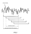
- FIG. 2 is a diagram schematically showing Fourier transform length and overlap length when a short-time Fourier transform process is performed on an input signal L (or input signal R) in the FFT unit 3.
- the FFT unit 3 works as a Fourier transform unit of the present invention.
- the FFT unit 3 transforms two-channel frequency spectra, which are calculated by frequency-region conversion, to amplitude spectrum signals Lfa and Rfa (first amplitude spectrum signals) and phase spectrum signals Lfp and Rfp. Then, the FFT unit 3 outputs the transformed two-channel amplitude spectrum signals Lfa and Rfa to the frequency spectrum region filtering unit 4. Moreover, the FFT unit 3 outputs the two-channel phase spectrum signals Lfp and Rfp to the IFFT unit 5a and the IFFT unit 5b. In this case, the FFT unit 3 transforms the input signals to the amplitude spectrum signals Lfa and Rfa and the phase spectrum signals Lfp and Rfp. Therefore, the FFT unit 3 works as a spectrum transform unit of the present invention.
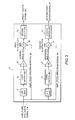
- FIG. 3 is a block diagram showing the schematic configuration of the frequency spectrum region filtering unit 4.
- the frequency spectrum region filtering unit 4 is designed to extract non-stationary and stationary signals by carrying out a simple filtering process for each spectrum. Incidentally, in the process by the frequency spectrum region filtering unit 4, a filtering process is performed only on the amplitude spectrum signals Lfa and Rfa, and no filtering process is performed on the phase spectrum signals Lfp and Rfp.
- the frequency spectrum region filtering unit 4 includes a LPF unit (low-pass filter unit) 10, a HPF unit (high-pass filter unit) 11, a first limiter unit 12, a second limiter unit 13, a third limiter unit 14, a fourth limiter unit 15, a first gain unit 16, a second gain unit 17, a first subtraction unit 18, and a second subtraction unit 19.
- FIG. 3 shows only the functional units (the LPF unit 10, the HPF unit 11, the limiter units 12 to 15, the gain units 16 and 17, and the subtraction units 18 and 19) designed to perform processes on the amplitude spectrum signal Lfa.
- FIG. 3 does not show the functional units designed to perform processes on the amplitude spectrum signal Rfa. However, similar functional units are so provided as to perform processes on the amplitude spectrum signal Rfa, and similar filtering processes are carried out.
- the LPF unit 10 is designed to perform, on the basis of a predetermined normalized cutoff frequency, a low-pass filtering process for each spectrum (each frequency) on the amplitude spectrum signal Lfa that is input from the FFT unit 3.
- the first limiter unit 12 is designed to limit the negative-side amplitude of the amplitude spectrum signal (second amplitude spectrum signal) on which the low-pass filtering process has been performed by the LPF unit 10, thereby bringing the amplitude to zero.
- the first gain unit 16 is designed to amplify or attenuate the amplitude of the amplitude spectrum signal whose negative-side amplitude has been limited. In this manner, in the LPF unit 10, the low-pass filtering process is carried out on the amplitude spectrum signal Lfa. As a result, a signal (integral signal: second amplitude spectrum signal) Lfa1 that has been integrated for each spectrum is generated.
- the first subtraction unit 18 subtracts, from the amplitude spectrum signal Lfa that is input from the FFT unit 3, the integral signal Lfa1 that is input from the first gain unit 16, thereby calculating a non-stationary spectrum signal (third amplitude spectrum signal) that changes with time. Then, the second limiter unit 13 limits the negative-side amplitude of the spectrum signal (third amplitude spectrum signal) calculated by the first subtraction unit 18, thereby bringing the amplitude to zero.
- the signal whose amplitude has been limited by the second limiter unit 13 is output as a direct sound signal Lfd to the IFFT unit 5a.
- the HPF unit 11 is designed to perform, on the basis of a predetermined normalized cutoff frequency, a high-pass filtering process for each spectrum (each frequency) on the amplitude spectrum signal Lfa that is input from the FFT unit 3.
- the third limiter unit 14 is designed to limit the negative-side amplitude of the amplitude spectrum signal (fourth amplitude spectrum signal) on which the high-pass filtering process has been performed by the HPF unit 11, thereby bringing the amplitude to zero.
- the second gain unit 17 is designed to amplify or attenuate the amplitude of the amplitude spectrum signal whose negative-side amplitude has been limited. In this manner, in the HPF unit 11, the high-pass filtering process is carried out on the amplitude spectrum signal Lfa. As a result, a signal (differential signal: fourth amplitude spectrum signal) Lfa2 that has been differentiated for each spectrum is generated.
- the second subtraction unit 19 subtracts, from the amplitude spectrum signal Lfa that is input from the FFT unit 3, the differential signal Lfa2 that is input from the second gain unit 17, thereby calculating a stationary spectrum signal (fifth amplitude spectrum signal) that slightly changes with time. Then, the fourth limiter unit 15 limits the negative-side amplitude of the spectrum signal (fifth amplitude spectrum signal) calculated by the second subtraction unit 19, thereby bringing the amplitude to zero. The signal whose amplitude has been limited by the fourth limiter unit 15 is output as a reverberant sound signal Lfr to the IFFT unit 5b.
- the normalized cutoff frequency of a low-pass filter of each amplitude spectrum in the LPF unit 10 and the normalized cutoff frequency of a high-pass filter of each amplitude spectrum in the HPF unit 11 are those used to adjust the division time of the direct sound and reverberant sound (or those used to adjust the extraction time of the direct sound, and to adjust the extraction time of the reverberant sound).
- the first gain unit 16 and the second gain unit 17 by changing an amount of weighting of amplification and attenuation, it becomes possible to adjust a blend ratio of the direct sound and reverberant sound (or to adjust the percentage of the reverberant sound contained in the direct sound, as well as to adjust the percentage of the direct sound contained in the reverberant sound).
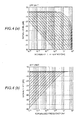
- FIG. 4(a) shows one example of filter coefficients for each amplitude spectrum in the LPF unit 10 according to the present embodiment.
- FIG. 4(b) shows one example of filter coefficients for each amplitude spectrum in the HPF unit 11 according to the present embodiment.
- the LPF unit 10 and HPF unit 11 shown in FIGS. 4(a) and 4(b) are first-order Butterworth filters.
- the normalized cutoff frequency of the LPF unit 10 and the HPF unit 11 is changed to 0.000001, 0.000002, 0.000004 « and 0.0655. As the value of the cutoff frequency becomes smaller, the extraction time of the direct sound and the extraction time of the reverberant sound become longer.
- the cutoff frequencies of the LPF unit 10 and the HPF unit 11 are so set as to be the same across the amplitude spectra.
- the cutoff frequencies of the LPF unit 10 and the HPF unit 11 may be set independently for each amplitude spectrum.
- FIG. 5(a) is a diagram showing one example of frequency changes of an amount of weighting of amplification and attenuation of the first gain unit 16 according to the present embodiment.
- FIG. 5(b) is a diagram showing one example of frequency changes of an amount of weighting of amplification and attenuation of the second gain unit 17.
- the first gain unit 16 and second gain unit 17 of the present embodiment as the gain (signal level) becomes smaller, the mixed quantity becomes larger.
- the direct sound-side first gain unit 16 at an amplitude spectrum of 500Hz or less, the separation of the direct sound and the reverberant sound is hardly carried out.
- FIGS. 6 to 9 show an example of operation of each part of the frequency spectrum region filtering unit 4, and are diagrams showing, as an example, time changes of the amplitude of an input signal (amplitude spectrum signal Lfa) that is input into the frequency spectrum region filtering unit 4, the amplitude of the integral signal Lfa1, the amplitude of the differential signal Lfa2, the amplitude of the direct sound signal Lfd, and the amplitude of the reverberant sound signal Lfr.
- the waveforms shown in FIGS. 6 to 9 all are the results of observing the time changes of an amplitude spectrum around 1 kHz.
- a sampling rate of the input signal is 44.1 kHz
- the Fourier transform length of the FFT unit 3 is 4096 samples
- the overlap length is 3840 samples, which is fifteen-sixteenths of the Fourier transform length
- the window function of the Fourier transform is Blackman.
- the input signals shown in FIGS. 6 to 8 are sine waves of 1 kHz with a reproduction time of 1 second.
- the input signals shown in FIG. 9 are of music.
- FIGS. 8 and 9 What is shown in FIGS. 8 and 9 is the case where weighting is carried out for each of the spectra (each of the frequencies) shown in FIGS. 5(a) and 5(b) in the first gain unit 16 and the second gain unit 17. What is shown in FIGS. 6 and 7 is the case where weighting is not carried out in the first gain unit 16 and the second gain unit 17, with the gain (signal level) for all amplitude spectra set to 0 dB.
- the LPF unit 10 performs a low-pass filtering process to carry out an integration process of the input signal Lfa having a rectangular shape. Accordingly, a rising portion of the rectangular input signal Lfa is extracted, and an integral signal Lfa1 whose amplitude rises gradually is generated. After that, in the first subtraction unit 18, the integral signal Lfa1 is subtracted from the input signal Lfa. Therefore, from the rectangular shape of the input signal Lfa, the amplitude of the gradually-rising portion of the integral signal Lfa1 is subtracted. As a result, the rising portion of the rectangular signal, i.e. non-stationary component, is extracted as a direct sound signal Lfd.
- the subtraction process by the first subtraction unit 18 makes the amplitude of the direct sound signal Lfd negative.
- the amplitude has been limited by the second limiter unit 13 and brought to zero, as shown in FIG. 6(a) , the value of the direct sound signal Lfd is not negative.
- the HPF unit 11 performs a high-pass filtering process to carry out a differential process of the input signal Lfa having a rectangular shape. Accordingly, a differential signal Lfa2, which has a sharp rising portion of the rectangular input signal Lfa and a subsequent gradually-attenuating portion, is generated. After that, in the second subtraction unit 19, the differential signal Lfa2 is subtracted from the input signal Lfa. Therefore, from the rectangular shape of the input signal Lfa, the amplitudes of the sharp rising portion of the differential signal Lfa2 and the like are subtracted. As a result, a portion other than the rising portions of the rectangular signal, i.e. stationary component, is extracted as a reverberant sound signal Lfr.
- the subtraction process by the second subtraction unit 19, too makes the amplitude of the reverberant sound signal Lfr negative.
- the amplitude has been limited by the fourth limiter unit 15 and brought to zero, as shown in FIG. 6(b) , the value of the reverberant sound signal Lfr is not negative.
- FIG. 7 is a diagram showing the case in which the normalized cutoff frequencies of the HPF unit 11 and the LPF unit 10 are changed in the situation shown in FIG. 6 . More specifically, the normalized cutoff frequency of the HPF unit 11 shown in FIG. 7(b) is set to 0.0041, which is a value lower than the normalized cutoff frequency, 0.0082, of the HPF unit 11 shown in FIG. 6(b) . The normalized cutoff frequency of the LPF unit 10 shown in FIG. 7(a) is set to 0.0164, which is a value higher than the normalized cutoff frequency, 0.0082, of the LPF unit 10 shown in FIG. 6(a) .
- the cutoff frequencies are adjusted, and thus it is possible to adjust the division time of the direct sound and reverberant sound (or to adjust the extraction time of the direct sound, and to adjust the extraction time of the reverberant sound).
- FIG. 8 is a diagram showing the case in which an amount of weighting for each spectrum in the first gain unit 16 and the second gain unit 17 is set in the situation shown in FIG. 6 .
- an offset or raising of amplitude
- a reverberant sound associated with the offset is added (raising of amplitude with a height of L1 as shown in FIG. 8(a) ).
- Lfr a reverberant sound signal
- a direct sound associated with the offset is added (raising of amplitude with a height of L1 as shown in FIG. 8(b) ).
- the offset that is generated as the amount of weighting is set, it is possible to adjust the blend ratio of the direct sound and reverberant sound (or to adjust the percentage of the reverberant sound contained in the direct sound, as well as to adjust the percentage of the direct sound contained in the reverberant sound).
- FIG. 9 is a diagram showing the case in which, in the situation shown in FIG. 8 , an input signal is of a music signal, and components around 1kHz that attenuate with time are extracted.
- an input signal is of a music signal, and components around 1kHz that attenuate with time are extracted.
- FIG. 9(a) as for a direct sound-side signal, a signal of direct sound is extracted in the first half in which the amplitude is large.
- FIG. 9(b) as for a reverberant sound-side signal, a signal of reverberant sound is extracted in the latter half in which the amplitude of an input signal is attenuated.
- the IFFT unit 5a converts, on the basis of the amplitude spectrum signals (direct sound signals Lfd and Rfd) that are made from the direct sound filtered by the frequency spectrum region filtering unit 4 and the phase spectrum signals Lfp and Rfp acquired from the FFT unit 3, to frequency spectra of real and imaginary numbers; and carries out a process of weighting by using a window function. Then, the IFFT unit 5a performs a short-time inverse Fourier transform process and an overlap addition process on a signal on which the weighting process has been performed, thereby converting the signal from the frequency domain to the time domain and generating direct sound signals Ld and Rd that are made from the direct sound.
- the IFFT unit 5b converts, on the basis of the amplitude spectrum signals (reverberant sound signals Lfr and Rfr) that are made from the reverberant sound filtered by the frequency spectrum region filtering unit 4 and the phase spectrum signals Lfp and Rfp acquired from the FFT unit 3, to frequency spectra of real and imaginary numbers; and carries out a process of weighting by using a window function. Then, the IFFT unit 5b performs a short-time inverse Fourier transform process and an overlap addition process on a signal on which the weighting process has been performed, thereby converting the signal from the frequency domain to the time domain and generating reverberant sound signals Lr and Rr that are made from the reverberant sound.
- the IFFT units 5a and 5b carry out, on the basis of the amplitude spectrum signals and the phase spectrum signals, a process of converting to frequency spectra of real and imaginary numbers. Therefore, the IFFT units 5a and 5b correspond to an inverse spectrum transform unit of the present invention. Furthermore, the IFFT units 5a and 5b carry out a short-time inverse Fourier transform process on a signal on which the weighting process has been performed. Therefore, the IFFT units 5a and 5b correspond to an inverse Fourier transform unit of the present invention.
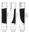
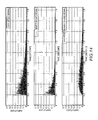
- FIGS. 10 to 14 are diagrams showing, as an example, time changes of the amplitude of the input signal to the acoustic processing device 1, and the amplitudes of the direct sound signal and reverberant sound signal that are extracted (generated) in the acoustic processing device 1.
- FIGS. 10 and 11 show the case where a sine wave of 1kHz with a reproduction time of 1 second is input as the input signal.
- FIGS. 12 and 13 show the case where music is input as the input signal.
- FIG. 14 shows the case where an impulse response in a hall (or in an environment where a reverberant sound can easily occur) is input as the input signal.
- FIGS. 10 to 14 all the normalized cutoff frequencies of the HPF unit 11 and the LPF unit 10 are 0.0082.
- FIGS. 10 , 12 , and 14 show the case where the weighting process for each spectrum is not carried out.
- FIGS. 11 and 13 show the case where the weighting process for each spectrum (for each frequency) is carried out.
- the inverse Fourier transform length of the IFFT units 5a and 5b is 4096 samples
- the overlap length is 3840 samples, which is fifteen-sixteenths of the Fourier transform length
- the window function of the inverse Fourier transform is Blackman. The same settings are true for FFT unit 3.
- FIGS. 10 and 11 show the situation where, with respect to the time changes of the amplitude of the rectangular input signal, the direct sound signal, which is a non-stationary component, and the reverberant sound signal, which is a stationary component, are extracted.
- the values of amplitudes of the direct sound signal and reverberant sound signal shown in FIG. 11 have been offset by the weighting process for each spectrum. Therefore, in an offset portion (or a portion in which the amplitudes of the direct sound signal and reverberant sound signal are raised by a height of L2 in the case of FIG. 11 ), a portion including a mixture of direct sound and reverberant sound is contained.
- the weighting process by the first gain unit 16 and the second gain unit 17 it is possible to adjust the blend ratio of the direct sound and reverberant sound.
- the waveforms that are obtained by extracting the direct sound and the reverberant sound can be confirmed.
- the separated direct sound and reverberant sound are separately heard, it is possible to confirm both the direct sound and reverberant sound of the music. It is possible to aurally recognize the extraction (or separation) of the direct sound and reverberant sound.
- the setting of weighting for each spectrum is carried out. Therefore, the waveforms that are obtained as the reverberant sound is partially added in the direct sound and as the direct sound is partially added in the reverberant sound can be confirmed (The heights of amplitudes of the direct sound signal and reverberant sound signal in FIG. 13 are higher than in FIG. 12 ). Therefore, it is confirmed that the blend ratio of the direct sound and reverberant sound can be adjusted by the setting of weighting for each spectrum. Even if the direct sound and reverberant sound shown in FIG. 13 are heard, an output sound into which the direct sound and the reverberant sound have been blended according to the blend ratio can be confirmed.
- an impulse response in a hall is input as the input signal. Because of the impulse response, there is an output at a time when a very short signal is input, and the output has a property of converging in amplitude for a short period of time. However, because of the impulse response in the hall that is an environment where a reverberant sound can easily occur, in addition to the direct sound, a lot of reverberant sound would be contained.
- the normalized cutoff frequencies of the HPF unit 11 and the LPF unit 10 are set to 0.0082. However, by adjusting the values of the normalized cutoff frequencies, it is possible to adjust the extraction time of the direct sound and the extraction time of the reverberant sound.
- FIG. 15(a) is a diagram schematically showing a state in which the waveform of the direct sound shown in FIG. 14 varies according to how the value of a normalized cutoff frequency is adjusted, and the input signal.
- the value of the normalized cutoff frequency becomes larger, the time required for the amplitude of the impulse response to converge becomes shorter.
- the time required for the amplitude of the impulse response to converge becomes longer, showing the shape of waveform that is close to the converged state of the amplitude of the input signal.
- the value of the normalized cutoff frequency it is possible to change the extraction time of the direct sound in the input signal. Accordingly, as the value of the normalized cutoff frequency is decreased, the extraction time of the direct sound in the input signal becomes longer, enabling extraction of the direct sound in such a way as to contain not only a non-stationary sound but also a stationary sound. For example, to an extent shown in FIG. 14 , the extraction of the direct sound containing the stationary sound is carried out. Therefore, compared with the direct sound that does not contain a stationary sound at all, it is possible to add such properties as tone colors and ease of listening to the direct sound. When a listener listens to the direct sound, the listener can recognize the direct sound as a sound without a feeling of strangeness.
- FIG. 15(b) is a diagram schematically showing a state in which the waveform of the reverberant sound shown in FIG. 14 varies according to how the value of a normalized cutoff frequency is adjusted, and the input signal.
- the amplitude of the reverberant sound begins to increase early on, and the increase in the amplitude of the reverberant sound tends to dramatically rise early on.
- the value of the normalized cutoff frequency becomes smaller, the increase in the amplitude of the reverberant sound (or a rising portion) becomes gradual.
- the value of the normalized cutoff frequency it is possible to change the extraction time of the direct sound in the input signal.
- By decreasing the value of the normalized cutoff frequency it is possible to reduce the effects of the direct sound contained in the reverberant sound signal.
- By increasing the value of the normalized cutoff frequency it is possible to extract the reverberant sound signal that contains a small amount of direct sound.
- a direct sound signal is extracted by the direct sound extraction device; the direct sound signal is output from a speaker, which is placed near a listener.
- the direct sound signal is output from a speaker, which is placed near a listener.
- a reverberant sound signal is extracted by the reverberant sound extraction device from the input signal; and the reverberant sound signal is output from a speaker, which is placed distant from the listener. As a result, it is possible to output the reverberant sound in an effective manner.
Landscapes
- Engineering & Computer Science (AREA)
- Acoustics & Sound (AREA)
- Physics & Mathematics (AREA)
- Signal Processing (AREA)
- Health & Medical Sciences (AREA)
- Computational Linguistics (AREA)
- Human Computer Interaction (AREA)
- Quality & Reliability (AREA)
- Audiology, Speech & Language Pathology (AREA)
- Multimedia (AREA)
- Otolaryngology (AREA)
- General Health & Medical Sciences (AREA)
- Tone Control, Compression And Expansion, Limiting Amplitude (AREA)
- Circuit For Audible Band Transducer (AREA)
- Stereophonic System (AREA)
- Reverberation, Karaoke And Other Acoustics (AREA)
Abstract
Description
- The present invention relates to a direct sound extraction device and a reverberant sound extraction device, and more particularly to a direct sound extraction device that can extract a direct sound from an input signal containing a reverberant sound, and a reverberant sound extraction device that can extract a reverberant sound from the input signal.
- If music, speeches, and the like are played in an environment where reverberation can easily occur, such as halls, and are recorded, the recorded acoustic signals often contain not only a direct sound but also a reverberant sound, which is convoluted in during the recording. Therefore, if the acoustic signals into which the reverberant sound has been convoluted are played in another acoustic environment, there is a reduction in the clarity of the direct sound, possibly making it very difficult to listen when the acoustic signals are played.
- If a speech sound into which a reverberant sound has been convoluted is used for voice recognition or the like, the problem is that the recognition rate of the speech sound (content) would decrease due to a reduction in the clarity caused by the reverberant sound.
- As for the acoustic signals into which the reverberant sound has been convoluted as described above, a conventional technique has been known to reduce the reverberant sound (See
Patent Literature 1, for example). The use of the technique makes it possible to clarify the direct sound by reducing the reverberant sound. - Patent Literature 1:
JP-A-2010-74531 - However, according to the method described in
Patent Literature 1, in order to reduce the reverberant sound contained in an input signal, various types of signal processing need to be carried out, such as a pseudo-whitening process, a multi-step linear prediction process, and a rear reverberation prediction process and the like. Therefore, a lot of processing load is required. Accordingly, to actually reduce the reverberant sound, high-powered devices, such as microprocessors or digital signal processors, are required. The problem is that, in terms of cost and other factors, the method ofPatent Literature 1 easily cannot be used without being changed. - The present invention has been made in view of the above problems. The object of the present invention is to provide a direct sound extraction device and reverberant sound extraction device that can easily extract a direct sound or a reverberant sound from an acoustic signal containing the reverberant sound.
- According to the present invention, a direct sound extraction device includes: a Fourier transform unit which performs a Fourier transform process on an input signal that includes a reverberant sound in a direct sound; a spectrum transform unit which transforms, on the basis of frequency spectra of real and imaginary numbers of the input signal on which a Fourier transform process has been performed by the Fourier transform unit, the input signal to a first amplitude spectrum signal and a phase spectrum signal; a low-pass filter unit which carries out a low-pass filtering process on the first amplitude spectrum signal by using a preset normalized cutoff frequency for each frequency; a first limiter unit which limits a negative side of an amplitude of a second amplitude spectrum signal on which a low-pass filtering process has been performed by the low-pass filter unit, so as to bring the amplitude to zero; a first subtraction unit which calculates a third amplitude spectrum signal by subtracting the second amplitude spectrum signal whose negative-side amplitude has been limited by the first limiter unit from the first amplitude spectrum signal; a second limiter unit which limits a negative side of an amplitude of the third amplitude spectrum signal calculated by the first subtraction unit, so as to bring the amplitude to zero; an inverse spectrum transform unit which calculates, on the basis of the phase spectrum signal and the third amplitude spectrum signal whose negative-side amplitude has been limited by the second limiter unit, a signal that is made from frequency spectra of real and imaginary numbers; and an inverse Fourier transform unit which performs an inverse Fourier transform process on the signal calculated by the inverse spectrum transform unit to generate a direct sound signal that is obtained by extracting the direct sound from the input signal.
- The direct sound extraction device of the present invention performs Fourier transform of an input signal that includes a reverberant sound in a direct sound, and uses a preset normalized cutoff frequency to carry out a low-pass filtering process on a first amplitude spectrum signal calculated by the spectrum transform unit. In this manner, the direct sound extraction device calculates a signal that is integrated for each spectrum (Integral signal: second amplitude spectrum signal). The signal thus integrated is the equivalent of a spectrum signal that constitutes a stationary component in the time change of the input signal, i.e. a reverberant sound signal.
- Accordingly, a third amplitude spectrum signal that the first subtraction unit calculates by subtracting the second amplitude spectrum signal from the first amplitude spectrum signal is a signal that is obtained by subtracting a reverberant sound from an input signal. The process makes it possible to calculate a signal that is the equivalent of a direct sound signal.
- Therefore, a signal that is generated by the inverse spectrum transform unit and the inverse Fourier transform unit is a signal that is obtained by extracting a direct sound from the input signal. As a result, from the input signal that includes a reverberant sound in a direct sound, the direct sound can be easily extracted.
- Furthermore, by adjusting the normalized cutoff frequency, it is possible to adjust an extraction time of the direct sound contained in the input signal. As the value of the normalized cutoff frequency becomes smaller, the extraction time of the direct sound contained in the input signal becomes longer, enabling extraction of the direct sound in such a way as to contain not only a non-stationary sound but also a stationary sound. Since the direct sound is extracted in such a way as to contain a stationary sound, it is possible to add such properties as tone colors and ease of listening to the direct sound, compared with a direct sound not containing a stationary sound at all. When a listener listens to the direct sound, the listener can recognize the direct sound as a sound without a feeling of strangeness.
- The direct sound extraction device of the present invention can easily extract the direct sound from the input signal that includes the reverberant sound in the direct sound. The reverberant sound extraction device of the present invention can easily extract the reverberant sound from the input signal that includes the reverberant sound in the direct sound.
-
-
FIG. 1 is a block diagram showing, as one example, the schematic configuration of an acoustic processing device according to an embodiment of the present invention. -
FIG. 2 is a diagram schematically showing Fourier transform length and overlap length when a short-time Fourier transform process is performed on an input signal in an FFT unit according to an embodiment of the present invention. -
FIG. 3 is a block diagram showing, as one example, the schematic configuration of a frequency spectrum region filtering unit according to an embodiment of the present invention. -
FIG. 4(a) shows one example of filter coefficients for each amplitude spectrum in a LPF unit according to an embodiment of the present invention; andFIG. 4(b) shows one example of filter coefficients for each amplitude spectrum in a HPF unit. -
FIG. 5(a) is a diagram showing one example of frequency changes of an amount of weighting of amplification and attenuation of a first gain unit according to an embodiment of the present invention; andFIG. 5(b) is a diagram showing one example of frequency changes of an amount of weighting of amplification and attenuation of a second gain unit according to an embodiment of the present invention. -
FIG. 6 is a first diagram showing, as an example, time changes of the amplitude of an input signal that is input into a frequency spectrum region filtering unit, the amplitude of an integral signal Lfa1, the amplitude of a differential signal Lfa2, the amplitude of a direct sound signal Lfd, and the amplitude of a reverberant sound signal Lfr according to an embodiment of the present invention. -
FIG. 7 is a second diagram showing, as an example, time changes of the amplitude of an input signal that is input into a frequency spectrum region filtering unit, the amplitude of an integral signal Lfa1, the amplitude of a differential signal Lfa2, the amplitude of a direct sound signal Lfd, and the amplitude of a reverberant sound signal Lfr according to an embodiment of the present invention. -
FIG. 8 is a third diagram showing, as an example, time changes of the amplitude of an input signal that is input into a frequency spectrum region filtering unit, the amplitude of an integral signal Lfa1, the amplitude of a differential signal Lfa2, the amplitude of a direct sound signal Lfd, and the amplitude of a reverberant sound signal Lfr according to an embodiment of the present invention. -
FIG. 9 is a fourth diagram showing, as an example, time changes of the amplitude of an input signal that is input into a frequency spectrum region filtering unit, the amplitude of an integral signal Lfa1, the amplitude of a differential signal Lfa2, the amplitude of a direct sound signal Lfd, and the amplitude of a reverberant sound signal Lfr according to an embodiment of the present invention. -
FIG. 10 is a first diagram showing, as an example, time changes of the amplitude of an input signal in an acoustic processing device, the amplitudes of a direct sound signal and a reverberant sound signal that are extracted in the acoustic processing device according to an embodiment of the present invention. -
FIG. 11 is a second diagram showing, as an example, time changes of the amplitude of an input signal in an acoustic processing device, the amplitudes of a direct sound signal and a reverberant sound signal that are extracted in the acoustic processing device according to an embodiment of the present invention. -
FIG. 12 is a third diagram showing, as an example, time changes of the amplitude of an input signal in an acoustic processing device, the amplitudes of a direct sound signal and a reverberant sound signal that are extracted in the acoustic processing device according to an embodiment of the present invention. -
FIG. 13 is a fourth diagram showing, as an example, time changes of the amplitude of an input signal in an acoustic processing device, the amplitudes of a direct sound signal and a reverberant sound signal that are extracted in the acoustic processing device according to an embodiment of the present invention. -
FIG. 14 is a fifth diagram showing, as an example, time changes of the amplitude of an input signal in an acoustic processing device, the amplitudes of a direct sound signal and a reverberant sound signal that are extracted in the acoustic processing device according to an embodiment of the present invention. -
FIG. 15(a) is a diagram schematically showing a state in which the waveform of a direct sound signal shown inFIG. 14 varies according to how the value of a normalized cutoff frequency is adjusted, and an input signal; andFIG. 15(b) is a diagram schematically showing a state in which the waveform of a reverberant sound signal shown inFIG. 14 varies according to how the value of a normalized cutoff frequency is adjusted, and an input signal. - The following shows an acoustic processing device, which is an example of a direct sound extraction device and reverberant sound extraction device of the present invention. The acoustic processing device will be described in detail with reference to the accompanying drawings.
- Incidentally, when a reverberant sound is convoluted into a direct sound such as voice or instrumental sound, a stationary signal corresponding to a reverberation time is added to the non-stationary signal such as voice and instrumental sound in a frequency spectrum. The acoustic processing device of the present embodiment extracts or separates a non-stationary signal from an input signal to extract a direct sound; and extracts or separates a stationary signal from an input signal to extract a reverberant sound.
-
FIG. 1 is a block diagram showing the schematic configuration of the acoustic processing device. As shown inFIG. 1 , theacoustic processing device 1 includes an FFT unit (a Fourier transform unit and a spectrum transform unit) 3, a frequency spectrumregion filtering unit 4, and IFFT units (an inverse Fourier transform unit and an inverse spectrum transform unit) 5a and 5b. - Into the
FFT unit 3, two-channel input signals L and R (L-channel and R-channel) are input from a sound source unit not shown in the diagram: In the two-channel input signals L and R, a reverberant sound (e.g. a reflected sound in a speech) is convoluted into (or contained in) a direct sound (e.g. voice such as speech). TheFFT unit 3 is designed to use a window function to weight each of the two-channel input signals L and R into which the reverberant sound has been convoluted. - After having used the window function to weight, the
FFT unit 3 performs a short-time Fourier transform process on each of the input signals L and R, thereby transforming the input signals L and R from a time domain to a frequency domain and calculating frequency spectra of real and imaginary numbers.FIG. 2 is a diagram schematically showing Fourier transform length and overlap length when a short-time Fourier transform process is performed on an input signal L (or input signal R) in theFFT unit 3. In this case, because theFFT unit 3 performs a Fourier transform process on the input signals, theFFT unit 3 works as a Fourier transform unit of the present invention. - Furthermore, the
FFT unit 3 transforms two-channel frequency spectra, which are calculated by frequency-region conversion, to amplitude spectrum signals Lfa and Rfa (first amplitude spectrum signals) and phase spectrum signals Lfp and Rfp. Then, theFFT unit 3 outputs the transformed two-channel amplitude spectrum signals Lfa and Rfa to the frequency spectrumregion filtering unit 4. Moreover, theFFT unit 3 outputs the two-channel phase spectrum signals Lfp and Rfp to theIFFT unit 5a and theIFFT unit 5b. In this case, theFFT unit 3 transforms the input signals to the amplitude spectrum signals Lfa and Rfa and the phase spectrum signals Lfp and Rfp. Therefore, theFFT unit 3 works as a spectrum transform unit of the present invention. -
FIG. 3 is a block diagram showing the schematic configuration of the frequency spectrumregion filtering unit 4. The frequency spectrumregion filtering unit 4 is designed to extract non-stationary and stationary signals by carrying out a simple filtering process for each spectrum. Incidentally, in the process by the frequency spectrumregion filtering unit 4, a filtering process is performed only on the amplitude spectrum signals Lfa and Rfa, and no filtering process is performed on the phase spectrum signals Lfp and Rfp. - As shown in
FIG. 3 , the frequency spectrumregion filtering unit 4 includes a LPF unit (low-pass filter unit) 10, a HPF unit (high-pass filter unit) 11, afirst limiter unit 12, asecond limiter unit 13, athird limiter unit 14, afourth limiter unit 15, afirst gain unit 16, asecond gain unit 17, afirst subtraction unit 18, and asecond subtraction unit 19.FIG. 3 shows only the functional units (theLPF unit 10, theHPF unit 11, thelimiter units 12 to 15, thegain units subtraction units 18 and 19) designed to perform processes on the amplitude spectrum signal Lfa.FIG. 3 does not show the functional units designed to perform processes on the amplitude spectrum signal Rfa. However, similar functional units are so provided as to perform processes on the amplitude spectrum signal Rfa, and similar filtering processes are carried out. - The
LPF unit 10 is designed to perform, on the basis of a predetermined normalized cutoff frequency, a low-pass filtering process for each spectrum (each frequency) on the amplitude spectrum signal Lfa that is input from theFFT unit 3. Thefirst limiter unit 12 is designed to limit the negative-side amplitude of the amplitude spectrum signal (second amplitude spectrum signal) on which the low-pass filtering process has been performed by theLPF unit 10, thereby bringing the amplitude to zero. Thefirst gain unit 16 is designed to amplify or attenuate the amplitude of the amplitude spectrum signal whose negative-side amplitude has been limited. In this manner, in theLPF unit 10, the low-pass filtering process is carried out on the amplitude spectrum signal Lfa. As a result, a signal (integral signal: second amplitude spectrum signal) Lfa1 that has been integrated for each spectrum is generated. - The
first subtraction unit 18 subtracts, from the amplitude spectrum signal Lfa that is input from theFFT unit 3, the integral signal Lfa1 that is input from thefirst gain unit 16, thereby calculating a non-stationary spectrum signal (third amplitude spectrum signal) that changes with time. Then, thesecond limiter unit 13 limits the negative-side amplitude of the spectrum signal (third amplitude spectrum signal) calculated by thefirst subtraction unit 18, thereby bringing the amplitude to zero. The signal whose amplitude has been limited by thesecond limiter unit 13 is output as a direct sound signal Lfd to theIFFT unit 5a. - The
HPF unit 11 is designed to perform, on the basis of a predetermined normalized cutoff frequency, a high-pass filtering process for each spectrum (each frequency) on the amplitude spectrum signal Lfa that is input from theFFT unit 3. Thethird limiter unit 14 is designed to limit the negative-side amplitude of the amplitude spectrum signal (fourth amplitude spectrum signal) on which the high-pass filtering process has been performed by theHPF unit 11, thereby bringing the amplitude to zero. Thesecond gain unit 17 is designed to amplify or attenuate the amplitude of the amplitude spectrum signal whose negative-side amplitude has been limited. In this manner, in theHPF unit 11, the high-pass filtering process is carried out on the amplitude spectrum signal Lfa. As a result, a signal (differential signal: fourth amplitude spectrum signal) Lfa2 that has been differentiated for each spectrum is generated. - The
second subtraction unit 19 subtracts, from the amplitude spectrum signal Lfa that is input from theFFT unit 3, the differential signal Lfa2 that is input from thesecond gain unit 17, thereby calculating a stationary spectrum signal (fifth amplitude spectrum signal) that slightly changes with time. Then, thefourth limiter unit 15 limits the negative-side amplitude of the spectrum signal (fifth amplitude spectrum signal) calculated by thesecond subtraction unit 19, thereby bringing the amplitude to zero. The signal whose amplitude has been limited by thefourth limiter unit 15 is output as a reverberant sound signal Lfr to theIFFT unit 5b. - Incidentally, the normalized cutoff frequency of a low-pass filter of each amplitude spectrum in the
LPF unit 10, and the normalized cutoff frequency of a high-pass filter of each amplitude spectrum in theHPF unit 11 are those used to adjust the division time of the direct sound and reverberant sound (or those used to adjust the extraction time of the direct sound, and to adjust the extraction time of the reverberant sound). Moreover, in thefirst gain unit 16 and thesecond gain unit 17, by changing an amount of weighting of amplification and attenuation, it becomes possible to adjust a blend ratio of the direct sound and reverberant sound (or to adjust the percentage of the reverberant sound contained in the direct sound, as well as to adjust the percentage of the direct sound contained in the reverberant sound). -
FIG. 4(a) shows one example of filter coefficients for each amplitude spectrum in theLPF unit 10 according to the present embodiment.FIG. 4(b) shows one example of filter coefficients for each amplitude spectrum in theHPF unit 11 according to the present embodiment. TheLPF unit 10 andHPF unit 11 shown inFIGS. 4(a) and 4(b) are first-order Butterworth filters. As shown inFIG. 4 , the normalized cutoff frequency of theLPF unit 10 and theHPF unit 11 is changed to 0.000001, 0.000002, 0.000004...... and 0.0655. As the value of the cutoff frequency becomes smaller, the extraction time of the direct sound and the extraction time of the reverberant sound become longer. Incidentally, in the frequency spectrumregion filtering unit 4 of the present embodiment, the cutoff frequencies of theLPF unit 10 and theHPF unit 11 are so set as to be the same across the amplitude spectra. However, the cutoff frequencies of theLPF unit 10 and theHPF unit 11 may be set independently for each amplitude spectrum. -
FIG. 5(a) is a diagram showing one example of frequency changes of an amount of weighting of amplification and attenuation of thefirst gain unit 16 according to the present embodiment.FIG. 5(b) is a diagram showing one example of frequency changes of an amount of weighting of amplification and attenuation of thesecond gain unit 17. As shown inFIGS. 5(a) and 5(b) , in thefirst gain unit 16 andsecond gain unit 17 of the present embodiment, as the gain (signal level) becomes smaller, the mixed quantity becomes larger. Moreover, as shown inFIGS. 5(a) and 5(b) , in the direct sound-sidefirst gain unit 16, at an amplitude spectrum of 500Hz or less, the separation of the direct sound and the reverberant sound is hardly carried out. -
FIGS. 6 to 9 show an example of operation of each part of the frequency spectrumregion filtering unit 4, and are diagrams showing, as an example, time changes of the amplitude of an input signal (amplitude spectrum signal Lfa) that is input into the frequency spectrumregion filtering unit 4, the amplitude of the integral signal Lfa1, the amplitude of the differential signal Lfa2, the amplitude of the direct sound signal Lfd, and the amplitude of the reverberant sound signal Lfr. The waveforms shown inFIGS. 6 to 9 all are the results of observing the time changes of an amplitude spectrum around 1 kHz. - Incidentally, in the example of operation shown in
FIGS. 6 to 9 , a sampling rate of the input signal is 44.1 kHz, the Fourier transform length of theFFT unit 3 is 4096 samples, the overlap length is 3840 samples, which is fifteen-sixteenths of the Fourier transform length, and the window function of the Fourier transform is Blackman. The input signals shown inFIGS. 6 to 8 are sine waves of 1 kHz with a reproduction time of 1 second. The input signals shown inFIG. 9 are of music. - What is shown in
FIGS. 8 and9 is the case where weighting is carried out for each of the spectra (each of the frequencies) shown inFIGS. 5(a) and 5(b) in thefirst gain unit 16 and thesecond gain unit 17. What is shown inFIGS. 6 and7 is the case where weighting is not carried out in thefirst gain unit 16 and thesecond gain unit 17, with the gain (signal level) for all amplitude spectra set to 0 dB. - First, for a direct sound-side signal shown in
FIG. 6(a) , theLPF unit 10 performs a low-pass filtering process to carry out an integration process of the input signal Lfa having a rectangular shape. Accordingly, a rising portion of the rectangular input signal Lfa is extracted, and an integral signal Lfa1 whose amplitude rises gradually is generated. After that, in thefirst subtraction unit 18, the integral signal Lfa1 is subtracted from the input signal Lfa. Therefore, from the rectangular shape of the input signal Lfa, the amplitude of the gradually-rising portion of the integral signal Lfa1 is subtracted. As a result, the rising portion of the rectangular signal, i.e. non-stationary component, is extracted as a direct sound signal Lfd. - Incidentally, the subtraction process by the
first subtraction unit 18 makes the amplitude of the direct sound signal Lfd negative. However, since the amplitude has been limited by thesecond limiter unit 13 and brought to zero, as shown inFIG. 6(a) , the value of the direct sound signal Lfd is not negative. - Then, for a reverberant sound-side signal shown in
FIG. 6(b) , theHPF unit 11 performs a high-pass filtering process to carry out a differential process of the input signal Lfa having a rectangular shape. Accordingly, a differential signal Lfa2, which has a sharp rising portion of the rectangular input signal Lfa and a subsequent gradually-attenuating portion, is generated. After that, in thesecond subtraction unit 19, the differential signal Lfa2 is subtracted from the input signal Lfa. Therefore, from the rectangular shape of the input signal Lfa, the amplitudes of the sharp rising portion of the differential signal Lfa2 and the like are subtracted. As a result, a portion other than the rising portions of the rectangular signal, i.e. stationary component, is extracted as a reverberant sound signal Lfr. - Incidentally, the subtraction process by the
second subtraction unit 19, too, makes the amplitude of the reverberant sound signal Lfr negative. However, since the amplitude has been limited by thefourth limiter unit 15 and brought to zero, as shown inFIG. 6(b) , the value of the reverberant sound signal Lfr is not negative. -
FIG. 7 is a diagram showing the case in which the normalized cutoff frequencies of theHPF unit 11 and theLPF unit 10 are changed in the situation shown inFIG. 6 . More specifically, the normalized cutoff frequency of theHPF unit 11 shown inFIG. 7(b) is set to 0.0041, which is a value lower than the normalized cutoff frequency, 0.0082, of theHPF unit 11 shown inFIG. 6(b) . The normalized cutoff frequency of theLPF unit 10 shown inFIG. 7(a) is set to 0.0164, which is a value higher than the normalized cutoff frequency, 0.0082, of theLPF unit 10 shown inFIG. 6(a) . - As shown in
FIGS. 6 and7 , as the normalized cutoff frequencies become lower, the response of filters become slower, and the response of rising of signals become longer. As the normalized cutoff frequencies become higher, the response of filters become faster, and the response of rising of signals become shorter. In that manner, the cutoff frequencies are adjusted, and thus it is possible to adjust the division time of the direct sound and reverberant sound (or to adjust the extraction time of the direct sound, and to adjust the extraction time of the reverberant sound). -
FIG. 8 is a diagram showing the case in which an amount of weighting for each spectrum in thefirst gain unit 16 and thesecond gain unit 17 is set in the situation shown inFIG. 6 . As the amount of weighting is set, an offset (or raising of amplitude) is generated according to the amount of weighting in the direct sound and reverberant sound. Therefore, to a direct sound signal Lfd shown inFIG. 8(a) , a reverberant sound associated with the offset is added (raising of amplitude with a height of L1 as shown inFIG. 8(a) ). To a reverberant sound signal Lfr shown inFIG. 8(b) , a direct sound associated with the offset is added (raising of amplitude with a height of L1 as shown inFIG. 8(b) ). In that manner, with the help of the offset that is generated as the amount of weighting is set, it is possible to adjust the blend ratio of the direct sound and reverberant sound (or to adjust the percentage of the reverberant sound contained in the direct sound, as well as to adjust the percentage of the direct sound contained in the reverberant sound). -
FIG. 9 is a diagram showing the case in which, in the situation shown inFIG. 8 , an input signal is of a music signal, and components around 1kHz that attenuate with time are extracted. As shown inFIG. 9(a) , as for a direct sound-side signal, a signal of direct sound is extracted in the first half in which the amplitude is large. As shown inFIG. 9(b) , as for a reverberant sound-side signal, a signal of reverberant sound is extracted in the latter half in which the amplitude of an input signal is attenuated. - The
IFFT unit 5a converts, on the basis of the amplitude spectrum signals (direct sound signals Lfd and Rfd) that are made from the direct sound filtered by the frequency spectrumregion filtering unit 4 and the phase spectrum signals Lfp and Rfp acquired from theFFT unit 3, to frequency spectra of real and imaginary numbers; and carries out a process of weighting by using a window function. Then, theIFFT unit 5a performs a short-time inverse Fourier transform process and an overlap addition process on a signal on which the weighting process has been performed, thereby converting the signal from the frequency domain to the time domain and generating direct sound signals Ld and Rd that are made from the direct sound. - Similarly, the
IFFT unit 5b converts, on the basis of the amplitude spectrum signals (reverberant sound signals Lfr and Rfr) that are made from the reverberant sound filtered by the frequency spectrumregion filtering unit 4 and the phase spectrum signals Lfp and Rfp acquired from theFFT unit 3, to frequency spectra of real and imaginary numbers; and carries out a process of weighting by using a window function. Then, theIFFT unit 5b performs a short-time inverse Fourier transform process and an overlap addition process on a signal on which the weighting process has been performed, thereby converting the signal from the frequency domain to the time domain and generating reverberant sound signals Lr and Rr that are made from the reverberant sound. - Incidentally, the
IFFT units IFFT units IFFT units IFFT units -
FIGS. 10 to 14 are diagrams showing, as an example, time changes of the amplitude of the input signal to theacoustic processing device 1, and the amplitudes of the direct sound signal and reverberant sound signal that are extracted (generated) in theacoustic processing device 1.FIGS. 10 and11 show the case where a sine wave of 1kHz with a reproduction time of 1 second is input as the input signal.FIGS. 12 and13 show the case where music is input as the input signal.FIG. 14 shows the case where an impulse response in a hall (or in an environment where a reverberant sound can easily occur) is input as the input signal. - In the cases of
FIGS. 10 to 14 , all the normalized cutoff frequencies of theHPF unit 11 and theLPF unit 10 are 0.0082.FIGS. 10 ,12 , and14 show the case where the weighting process for each spectrum is not carried out.FIGS. 11 and13 show the case where the weighting process for each spectrum (for each frequency) is carried out. - In the cases of
FIGS. 10 to 14 , the inverse Fourier transform length of theIFFT units FFT unit 3. -
FIGS. 10 and11 show the situation where, with respect to the time changes of the amplitude of the rectangular input signal, the direct sound signal, which is a non-stationary component, and the reverberant sound signal, which is a stationary component, are extracted. As opposed to the direct sound signal and reverberant sound signal shown inFIG. 10 , the values of amplitudes of the direct sound signal and reverberant sound signal shown inFIG. 11 have been offset by the weighting process for each spectrum. Therefore, in an offset portion (or a portion in which the amplitudes of the direct sound signal and reverberant sound signal are raised by a height of L2 in the case ofFIG. 11 ), a portion including a mixture of direct sound and reverberant sound is contained. In accordance with the weighting process by thefirst gain unit 16 and thesecond gain unit 17, it is possible to adjust the blend ratio of the direct sound and reverberant sound. - In
FIGS. 12 and13 , with respect to the waveform of music (input signal), the waveforms that are obtained by extracting the direct sound and the reverberant sound can be confirmed. When the separated direct sound and reverberant sound are separately heard, it is possible to confirm both the direct sound and reverberant sound of the music. It is possible to aurally recognize the extraction (or separation) of the direct sound and reverberant sound. - In the case of
FIG. 13 , the setting of weighting for each spectrum is carried out. Therefore, the waveforms that are obtained as the reverberant sound is partially added in the direct sound and as the direct sound is partially added in the reverberant sound can be confirmed (The heights of amplitudes of the direct sound signal and reverberant sound signal inFIG. 13 are higher than inFIG. 12 ). Therefore, it is confirmed that the blend ratio of the direct sound and reverberant sound can be adjusted by the setting of weighting for each spectrum. Even if the direct sound and reverberant sound shown inFIG. 13 are heard, an output sound into which the direct sound and the reverberant sound have been blended according to the blend ratio can be confirmed. - In the case of
FIG. 14 , an impulse response in a hall is input as the input signal. Because of the impulse response, there is an output at a time when a very short signal is input, and the output has a property of converging in amplitude for a short period of time. However, because of the impulse response in the hall that is an environment where a reverberant sound can easily occur, in addition to the direct sound, a lot of reverberant sound would be contained. - In
FIG. 14 , the following can be confirmed: a direct sound whose amplitude has converged for a shorter period of time than the convergence of the amplitude of the input signal; and a reverberant sound whose amplitude has been maintained for a longer period of time than the convergence of the amplitude of the direct sound. In the case ofFIG. 14 , the normalized cutoff frequencies of theHPF unit 11 and theLPF unit 10 are set to 0.0082. However, by adjusting the values of the normalized cutoff frequencies, it is possible to adjust the extraction time of the direct sound and the extraction time of the reverberant sound. -
FIG. 15(a) is a diagram schematically showing a state in which the waveform of the direct sound shown inFIG. 14 varies according to how the value of a normalized cutoff frequency is adjusted, and the input signal. As shown inFIG. 15(a) , as the value of the normalized cutoff frequency becomes larger, the time required for the amplitude of the impulse response to converge becomes shorter. As the value of the normalized cutoff frequency becomes smaller, the time required for the amplitude of the impulse response to converge becomes longer, showing the shape of waveform that is close to the converged state of the amplitude of the input signal. - In that manner, by adjusting the value of the normalized cutoff frequency, it is possible to change the extraction time of the direct sound in the input signal. Accordingly, as the value of the normalized cutoff frequency is decreased, the extraction time of the direct sound in the input signal becomes longer, enabling extraction of the direct sound in such a way as to contain not only a non-stationary sound but also a stationary sound. For example, to an extent shown in
FIG. 14 , the extraction of the direct sound containing the stationary sound is carried out. Therefore, compared with the direct sound that does not contain a stationary sound at all, it is possible to add such properties as tone colors and ease of listening to the direct sound. When a listener listens to the direct sound, the listener can recognize the direct sound as a sound without a feeling of strangeness. -
FIG. 15(b) is a diagram schematically showing a state in which the waveform of the reverberant sound shown inFIG. 14 varies according to how the value of a normalized cutoff frequency is adjusted, and the input signal. As shown inFIG. 15(b) , as the value of the normalized cutoff frequency becomes larger, the amplitude of the reverberant sound begins to increase early on, and the increase in the amplitude of the reverberant sound tends to dramatically rise early on. As the value of the normalized cutoff frequency becomes smaller, the increase in the amplitude of the reverberant sound (or a rising portion) becomes gradual. - Accordingly, by adjusting the value of the normalized cutoff frequency, it is possible to change the extraction time of the direct sound in the input signal. By decreasing the value of the normalized cutoff frequency, it is possible to reduce the effects of the direct sound contained in the reverberant sound signal. By increasing the value of the normalized cutoff frequency, it is possible to extract the reverberant sound signal that contains a small amount of direct sound.
- Although the present invention has been described in detail with the reference to the accompanying drawings, the direct sound extraction device and reverberant sound extraction device of the present invention are not limited to the above embodiment. It will be apparent to those having ordinary skill in the art that a number of modifications or alternations to the invention as described herein may be made. All such modifications or alternations should therefore be seen as within the scope of the present invention.
- By utilizing the direct sound extraction device and reverberant sound extraction device of the present invention, it is also possible to build various acoustic environments. For example, from an input signal that includes a reverberant sound in a direct sound, a direct sound signal is extracted by the direct sound extraction device; the direct sound signal is output from a speaker, which is placed near a listener. As a result, compared with the case where the input signal is output from a speaker without being changed, it is possible to make a vocal sound clearer, thereby making it possible for the listener to easily listen. Moreover, a reverberant sound signal is extracted by the reverberant sound extraction device from the input signal; and the reverberant sound signal is output from a speaker, which is placed distant from the listener. As a result, it is possible to output the reverberant sound in an effective manner.
-
- 1: acoustic processing device (direct sound extraction device and reverberant sound extraction device)
- 3: FFT unit (Fourier transform unit and spectrum transform unit)
- 4 : frequency spectrum region filtering unit
- 5a, 5b: IFFT unit (inverse Fourier transform unit and inverse spectrum transform unit)
- 10: LPF unit (low-pass filter unit)
- 11: HPF unit (high-pass filter unit)
- 12: first limiter unit
- 13: second limiter unit
- 14: third limiter unit
- 15: fourth limiter unit
- 16: first gain unit
- 17: second gain unit
- 18: first subtraction unit
- 19: second subtraction unit
- L, R: input signal
- Lfa, Rfa: amplitude spectrum signal
- Lfp, Rfp: phase spectrum signal
- Lfa1: integral signal
- Lfa2: differential signal
- Lfd, Ld, Rfd, Rd: direct sound signal
- Lfr, Lr, Rfr, Rr: reverberant sound signal
Claims (4)
- A direct sound extraction device, comprising:a Fourier transform unit which performs a Fourier transform process on an input signal that includes a reverberant sound in a direct sound;a spectrum transform unit which transforms, on the basis of frequency spectra of real and imaginary numbers of the input signal on which a Fourier transform process has been performed by the Fourier transform unit, the input signal to a first amplitude spectrum signal and a phase spectrum signal;a low-pass filter unit which carries out a low-pass filtering process on the first amplitude spectrum signal by using a preset normalized cutoff frequency for each frequency;a first limiter unit which limits a negative side of an amplitude of a second amplitude spectrum signal on which a low-pass filtering process has been performed by the low-pass filter unit, so as to bring the amplitude to zero;a first subtraction unit which calculates a third amplitude spectrum signal by subtracting the second amplitude spectrum signal whose negative-side amplitude has been limited by the first limiter unit from the first amplitude spectrum signal;a second limiter unit which limits a negative side of an amplitude of the third amplitude spectrum signal calculated by the first subtraction unit, so as to bring the amplitude to zero;an inverse spectrum transform unit which calculates, on the basis of the phase spectrum signal and the third amplitude spectrum signal whose negative-side amplitude has been limited by the second limiter unit, a signal that is made from frequency spectra of real and imaginary numbers; andan inverse Fourier transform unit which performs an inverse Fourier transform process on the signal calculated by the inverse spectrum transform unit to generate a direct sound signal that is obtained by extracting the direct sound from the input signal.
- The direct sound extraction device according to claim 1, comprising
a first gain unit which performs weighting of the third amplitude spectrum signal by amplifying or attenuating, for each frequency, an amplitude of the third amplitude spectrum signal whose negative-side amplitude has been limited by the second limiter unit, wherein
the inverse spectrum transform unit calculates, on the basis of the phase spectrum signal and the third amplitude spectrum signal weighted by the first gain unit, a signal that is made from frequency spectra of real and imaginary numbers. - A reverberant sound extraction device, comprising:a Fourier transform unit which performs a Fourier transform process on an input signal that includes a reverberant sound in a direct sound;a spectrum transform unit which transforms, on the basis of frequency spectra of real and imaginary numbers of the input signal on which a Fourier transform process has been performed by the Fourier transform unit, the input signal to a first amplitude spectrum signal and a phase spectrum signal;a high-pass filter unit which carries out a high-pass filtering process on the first amplitude spectrum signal by using a preset normalized cutoff frequency for each frequency;a third limiter unit which limits a negative side of an amplitude of a fourth amplitude spectrum signal on which a high-pass filtering process has been performed by the high-pass filter unit, so as to bring the amplitude to zero;a second subtraction unit which calculates a fifth amplitude spectrum signal by subtracting the fourth amplitude spectrum signal whose negative-side amplitude has been limited by the third limiter unit from the first amplitude spectrum signal;a fourth limiter unit which limits a negative side of an amplitude of the fifth amplitude spectrum signal calculated by the second subtraction unit, so as to bring the amplitude to zero;an inverse spectrum transform unit which calculates, on the basis of the phase spectrum signal and the fifth amplitude spectrum signal whose negative-side amplitude has been limited by the fourth limiter unit, a signal that is made from frequency spectra of real and imaginary numbers; andan inverse Fourier transform unit which performs an inverse Fourier transform process on the signal calculated by the inverse spectrum transform unit to generate a reverberant sound signal that is obtained by extracting the reverberant sound from the input signal.
- The reverberant sound extraction device according to claim 3, comprising
a second gain unit which performs weighting of the fifth amplitude spectrum signal by amplifying or attenuating, for each frequency, an amplitude of the fifth amplitude spectrum signal whose negative-side amplitude has been limited by the fourth limiter unit, wherein
the inverse spectrum transform unit calculates, on the basis of the phase spectrum signal and the fifth amplitude spectrum signal weighted by the second gain unit, a signal that is made from frequency spectra of real and imaginary numbers.
Applications Claiming Priority (2)
| Application Number | Priority Date | Filing Date | Title |
|---|---|---|---|
| JP2011147021A JP5654955B2 (en) | 2011-07-01 | 2011-07-01 | Direct sound extraction device and reverberation sound extraction device |
| PCT/JP2012/065222 WO2013005550A1 (en) | 2011-07-01 | 2012-06-14 | Direct sound extraction device and reverberant sound extraction device |
Publications (3)
| Publication Number | Publication Date |
|---|---|
| EP2690623A1 true EP2690623A1 (en) | 2014-01-29 |
| EP2690623A4 EP2690623A4 (en) | 2015-04-15 |
| EP2690623B1 EP2690623B1 (en) | 2021-03-17 |
Family
ID=47436907
Family Applications (1)
| Application Number | Title | Priority Date | Filing Date |
|---|---|---|---|
| EP12807065.3A Not-in-force EP2690623B1 (en) | 2011-07-01 | 2012-06-14 | Direct sound extraction device and reverberant sound extraction device |
Country Status (5)
| Country | Link |
|---|---|
| US (1) | US9241214B2 (en) |
| EP (1) | EP2690623B1 (en) |
| JP (1) | JP5654955B2 (en) |
| CN (1) | CN103503066B (en) |
| WO (1) | WO2013005550A1 (en) |
Families Citing this family (10)
| Publication number | Priority date | Publication date | Assignee | Title |
|---|---|---|---|---|
| JP5898534B2 (en) * | 2012-03-12 | 2016-04-06 | クラリオン株式会社 | Acoustic signal processing apparatus and acoustic signal processing method |
| JP5985306B2 (en) * | 2012-08-27 | 2016-09-06 | クラリオン株式会社 | Noise reduction apparatus and noise reduction method |
| JP6212348B2 (en) * | 2013-10-11 | 2017-10-11 | 日本放送協会 | Upmix device, sound reproduction device, sound amplification device, and program |
| DE102015110938B4 (en) * | 2015-07-07 | 2017-02-23 | Christoph Kemper | Method for modifying an impulse response of a sound transducer |
| US10037750B2 (en) * | 2016-02-17 | 2018-07-31 | RMXHTZ, Inc. | Systems and methods for analyzing components of audio tracks |
| US10425730B2 (en) | 2016-04-14 | 2019-09-24 | Harman International Industries, Incorporated | Neural network-based loudspeaker modeling with a deconvolution filter |
| EP3896625A1 (en) * | 2020-04-17 | 2021-10-20 | Tata Consultancy Services Limited | An adaptive filter based learning model for time series sensor signal classification on edge devices |
| CN115938376A (en) * | 2021-08-06 | 2023-04-07 | Jvc建伍株式会社 | Treatment device and treatment method |
| CN115862665B (en) * | 2023-02-27 | 2023-06-16 | 广州市迪声音响有限公司 | Visual curve interface system of echo reverberation effect parameters |
| CN118032122B (en) * | 2024-04-11 | 2024-06-28 | 国网山东省电力公司潍坊供电公司 | Anomaly detection method, device and medium based on GIS operation sound |
Family Cites Families (12)
| Publication number | Priority date | Publication date | Assignee | Title |
|---|---|---|---|---|
| US5710862A (en) * | 1993-06-30 | 1998-01-20 | Motorola, Inc. | Method and apparatus for reducing an undesirable characteristic of a spectral estimate of a noise signal between occurrences of voice signals |
| JP3616139B2 (en) * | 1994-07-26 | 2005-02-02 | ローレルバンクマシン株式会社 | Display device in banknote handling machine |
| JPH0844390A (en) * | 1994-07-26 | 1996-02-16 | Matsushita Electric Ind Co Ltd | Voice recognition device |
| US6507623B1 (en) * | 1999-04-12 | 2003-01-14 | Telefonaktiebolaget Lm Ericsson (Publ) | Signal noise reduction by time-domain spectral subtraction |
| WO2006011104A1 (en) * | 2004-07-22 | 2006-02-02 | Koninklijke Philips Electronics N.V. | Audio signal dereverberation |
| EP1881489B1 (en) * | 2005-05-13 | 2010-11-17 | Panasonic Corporation | Mixed audio separation apparatus |
| JP4568193B2 (en) * | 2005-08-29 | 2010-10-27 | 日本電信電話株式会社 | Sound collecting apparatus and method, program and recording medium |
| JP2007065204A (en) * | 2005-08-30 | 2007-03-15 | Nippon Telegr & Teleph Corp <Ntt> | Reverberation removing apparatus, dereverberation removing method, dereverberation program and recording medium therefor |
| WO2007049644A1 (en) * | 2005-10-26 | 2007-05-03 | Nec Corporation | Echo suppressing method and device |
| US8271277B2 (en) * | 2006-03-03 | 2012-09-18 | Nippon Telegraph And Telephone Corporation | Dereverberation apparatus, dereverberation method, dereverberation program, and recording medium |
| JP4950971B2 (en) | 2008-09-18 | 2012-06-13 | 日本電信電話株式会社 | Reverberation removal apparatus, dereverberation method, dereverberation program, recording medium |
| WO2012159217A1 (en) * | 2011-05-23 | 2012-11-29 | Phonak Ag | A method of processing a signal in a hearing instrument, and hearing instrument |
-
2011
- 2011-07-01 JP JP2011147021A patent/JP5654955B2/en not_active Expired - Fee Related
-
2012
- 2012-06-14 US US14/112,941 patent/US9241214B2/en active Active
- 2012-06-14 WO PCT/JP2012/065222 patent/WO2013005550A1/en not_active Ceased
- 2012-06-14 EP EP12807065.3A patent/EP2690623B1/en not_active Not-in-force
- 2012-06-14 CN CN201280015523.2A patent/CN103503066B/en not_active Expired - Fee Related
Non-Patent Citations (5)
| Title |
|---|
| Anuradha R Fukane ET AL: "Different Approaches of Spectral Subtraction method for Enhancing the Speech Signal in Noisy Environments", International Journal of Scientific & Engineering Research, 1 March 2011 (2011-03-01), XP055172923, Retrieved from the Internet: URL:http://www.ijser.org/researchpaper/Different_Approaches_of_Spectral_Subtraction_method_for_Enhancing_the_Speech_Signal_in_Noisy_Environments.pdf [retrieved on 2015-03-02] * |
| HIRSCH H G: "Robust Speech Recognition in Noisy and Reverberant Environments", SPEECH RECOGNITION AND UNDERSTANDING : RECENT ADVANCES, TRENDS AND APPLICATIONS ; [PROCEEDINGS OF THE NATO ADVANCED STUDY INSTITUTE ON SPEECH RECOGNITION AND UNDERSTANDING. RECENT ADVANCES, TRENDS AND APPLICATIONS HELD IN CETRARO, ITALY, JULY 1 - 13,, vol. 75, no. Part 1, 1 January 1992 (1992-01-01), pages 101-106, XP008175013, DOI: 10.1007/978-3-642-76626-8_10 ISBN: 978-3-642-76628-2 * |
| LEBART K ET AL: "A NEW METHOD BASED ON SPECTRAL SUBTRACTION FOR SPEECH DEREVERBERATION", ACUSTICA, S. HIRZEL VERLAG, STUTTGART, DE, vol. 87, no. 3, 1 May 2001 (2001-05-01), pages 359-366, XP009053193, ISSN: 0001-7884 * |
| See also references of WO2013005550A1 * |
| Steven W Smith: "Chapter 14. Introduction to Digital Filters", The Scientist and Engineer's Guide to Digital Signal Processing, 1 January 2002 (2002-01-01), pages 261-276, XP055172473, Retrieved from the Internet: URL:http://www.analog.com/media/en/technical-documentation/dsp-book/dsp_book_Ch14.pdf [retrieved on 2015-02-26] * |
Also Published As
| Publication number | Publication date |
|---|---|
| JP5654955B2 (en) | 2015-01-14 |
| JP2013015606A (en) | 2013-01-24 |
| CN103503066A (en) | 2014-01-08 |
| WO2013005550A1 (en) | 2013-01-10 |
| EP2690623A4 (en) | 2015-04-15 |
| US20140044273A1 (en) | 2014-02-13 |
| US9241214B2 (en) | 2016-01-19 |
| CN103503066B (en) | 2015-07-01 |
| EP2690623B1 (en) | 2021-03-17 |
Similar Documents
| Publication | Publication Date | Title |
|---|---|---|
| US9241214B2 (en) | Direct sound extraction device and reverberant sound extraction device | |
| EP2827330B1 (en) | Audio signal processing device and audio signal processing method | |
| EP1451812B1 (en) | Audio signal bandwidth extension | |
| CN102016984B (en) | System and method for dynamic sound delivery | |
| EP2984650B1 (en) | Audio data dereverberation | |
| CN103189912A (en) | Voice processor and voice processing method | |
| EP2579252A1 (en) | Stability and speech audibility improvements in hearing devices | |
| KR20170042709A (en) | A signal processing apparatus for enhancing a voice component within a multi-channal audio signal | |
| Kim et al. | Nonlinear enhancement of onset for robust speech recognition. | |
| JP6533959B2 (en) | Audio signal processing apparatus and audio signal processing method | |
| CN102860047B (en) | Hearing aid and method for controlling hearing aid | |
| CN109862463A (en) | Earphone voice playback method, earphone and computer readable storage medium thereof | |
| JP5985306B2 (en) | Noise reduction apparatus and noise reduction method | |
| EP2370971B1 (en) | An audio equipment and a signal processing method thereof | |
| RU2589298C1 (en) | Method of increasing legible and informative audio signals in the noise situation | |
| JP2001249676A (en) | Extraction method of fundamental period or fundamental frequency of periodic waveform with added noise | |
| JP2011141540A (en) | Voice signal processing device, television receiver, voice signal processing method, program and recording medium | |
| Qu | Exploration of a New Active Noise Cancellation Headset Based on Spectral Contrast Enhancement Technique | |
| Yang et al. | Environment-Aware Reconfigurable Noise Suppression | |
| CN109862470A (en) | Method for broadcasting to ear patient, earphone and computer readable storage medium thereof | |
| HK40131744A (en) | Automatic gain control device, echo removal device, automatic gain control method, and automatic gain control program | |
| Ohtsuki et al. | The effect of the musical noise suppression in speech noise reduction using RSF | |
| Cecchi et al. | A novel approach to channel decorrelation for stereo Acoustic Echo Cancellation based on missing fundamental... | |
| KR20070022206A (en) | System for Audio Signal Processing | |
| HK1146424A1 (en) | Device and method for generating a multi-channel signal using voice signal processing |
Legal Events
| Date | Code | Title | Description |
|---|---|---|---|
| PUAI | Public reference made under article 153(3) epc to a published international application that has entered the european phase |
Free format text: ORIGINAL CODE: 0009012 |
|
| 17P | Request for examination filed |
Effective date: 20131025 |
|
| AK | Designated contracting states |
Kind code of ref document: A1 Designated state(s): AL AT BE BG CH CY CZ DE DK EE ES FI FR GB GR HR HU IE IS IT LI LT LU LV MC MK MT NL NO PL PT RO RS SE SI SK SM TR |
|
| DAX | Request for extension of the european patent (deleted) | ||
| RA4 | Supplementary search report drawn up and despatched (corrected) |
Effective date: 20150318 |
|
| RIC1 | Information provided on ipc code assigned before grant |
Ipc: G10L 21/0232 20130101AFI20150312BHEP Ipc: H04R 3/02 20060101ALI20150312BHEP |
|
| STAA | Information on the status of an ep patent application or granted ep patent |
Free format text: STATUS: EXAMINATION IS IN PROGRESS |
|
| 17Q | First examination report despatched |
Effective date: 20170928 |
|
| REG | Reference to a national code |
Ref country code: DE Ref legal event code: R079 Ref document number: 602012074833 Country of ref document: DE Free format text: PREVIOUS MAIN CLASS: G10L0021020000 Ipc: H04R0027000000 |
|
| RIC1 | Information provided on ipc code assigned before grant |
Ipc: H04R 27/00 20060101AFI20200820BHEP Ipc: G10L 21/0208 20130101ALI20200820BHEP Ipc: H04S 7/00 20060101ALI20200820BHEP |
|
| GRAP | Despatch of communication of intention to grant a patent |
Free format text: ORIGINAL CODE: EPIDOSNIGR1 |
|
| STAA | Information on the status of an ep patent application or granted ep patent |
Free format text: STATUS: GRANT OF PATENT IS INTENDED |
|
| INTG | Intention to grant announced |
Effective date: 20201007 |
|
| GRAS | Grant fee paid |
Free format text: ORIGINAL CODE: EPIDOSNIGR3 |
|
| GRAA | (expected) grant |
Free format text: ORIGINAL CODE: 0009210 |
|
| STAA | Information on the status of an ep patent application or granted ep patent |
Free format text: STATUS: THE PATENT HAS BEEN GRANTED |
|
| AK | Designated contracting states |
Kind code of ref document: B1 Designated state(s): AL AT BE BG CH CY CZ DE DK EE ES FI FR GB GR HR HU IE IS IT LI LT LU LV MC MK MT NL NO PL PT RO RS SE SI SK SM TR |
|
| REG | Reference to a national code |
Ref country code: GB Ref legal event code: FG4D |
|
| REG | Reference to a national code |
Ref country code: CH Ref legal event code: EP |
|
| REG | Reference to a national code |
Ref country code: DE Ref legal event code: R096 Ref document number: 602012074833 Country of ref document: DE |
|
| REG | Reference to a national code |
Ref country code: IE Ref legal event code: FG4D |
|
| REG | Reference to a national code |
Ref country code: AT Ref legal event code: REF Ref document number: 1373382 Country of ref document: AT Kind code of ref document: T Effective date: 20210415 |
|
| REG | Reference to a national code |
Ref country code: LT Ref legal event code: MG9D |
|
| PG25 | Lapsed in a contracting state [announced via postgrant information from national office to epo] |
Ref country code: FI Free format text: LAPSE BECAUSE OF FAILURE TO SUBMIT A TRANSLATION OF THE DESCRIPTION OR TO PAY THE FEE WITHIN THE PRESCRIBED TIME-LIMIT Effective date: 20210317 Ref country code: HR Free format text: LAPSE BECAUSE OF FAILURE TO SUBMIT A TRANSLATION OF THE DESCRIPTION OR TO PAY THE FEE WITHIN THE PRESCRIBED TIME-LIMIT Effective date: 20210317 Ref country code: GR Free format text: LAPSE BECAUSE OF FAILURE TO SUBMIT A TRANSLATION OF THE DESCRIPTION OR TO PAY THE FEE WITHIN THE PRESCRIBED TIME-LIMIT Effective date: 20210618 Ref country code: BG Free format text: LAPSE BECAUSE OF FAILURE TO SUBMIT A TRANSLATION OF THE DESCRIPTION OR TO PAY THE FEE WITHIN THE PRESCRIBED TIME-LIMIT Effective date: 20210617 Ref country code: NO Free format text: LAPSE BECAUSE OF FAILURE TO SUBMIT A TRANSLATION OF THE DESCRIPTION OR TO PAY THE FEE WITHIN THE PRESCRIBED TIME-LIMIT Effective date: 20210617 |
|
| PGFP | Annual fee paid to national office [announced via postgrant information from national office to epo] |
Ref country code: DE Payment date: 20210610 Year of fee payment: 10 Ref country code: FR Payment date: 20210621 Year of fee payment: 10 |
|
| REG | Reference to a national code |
Ref country code: AT Ref legal event code: MK05 Ref document number: 1373382 Country of ref document: AT Kind code of ref document: T Effective date: 20210317 |
|
| REG | Reference to a national code |
Ref country code: NL Ref legal event code: MP Effective date: 20210317 |
|
| PG25 | Lapsed in a contracting state [announced via postgrant information from national office to epo] |
Ref country code: SE Free format text: LAPSE BECAUSE OF FAILURE TO SUBMIT A TRANSLATION OF THE DESCRIPTION OR TO PAY THE FEE WITHIN THE PRESCRIBED TIME-LIMIT Effective date: 20210317 Ref country code: LV Free format text: LAPSE BECAUSE OF FAILURE TO SUBMIT A TRANSLATION OF THE DESCRIPTION OR TO PAY THE FEE WITHIN THE PRESCRIBED TIME-LIMIT Effective date: 20210317 Ref country code: RS Free format text: LAPSE BECAUSE OF FAILURE TO SUBMIT A TRANSLATION OF THE DESCRIPTION OR TO PAY THE FEE WITHIN THE PRESCRIBED TIME-LIMIT Effective date: 20210317 |
|
| PG25 | Lapsed in a contracting state [announced via postgrant information from national office to epo] |
Ref country code: NL Free format text: LAPSE BECAUSE OF FAILURE TO SUBMIT A TRANSLATION OF THE DESCRIPTION OR TO PAY THE FEE WITHIN THE PRESCRIBED TIME-LIMIT Effective date: 20210317 |
|
| PG25 | Lapsed in a contracting state [announced via postgrant information from national office to epo] |
Ref country code: AT Free format text: LAPSE BECAUSE OF FAILURE TO SUBMIT A TRANSLATION OF THE DESCRIPTION OR TO PAY THE FEE WITHIN THE PRESCRIBED TIME-LIMIT Effective date: 20210317 Ref country code: SM Free format text: LAPSE BECAUSE OF FAILURE TO SUBMIT A TRANSLATION OF THE DESCRIPTION OR TO PAY THE FEE WITHIN THE PRESCRIBED TIME-LIMIT Effective date: 20210317 Ref country code: LT Free format text: LAPSE BECAUSE OF FAILURE TO SUBMIT A TRANSLATION OF THE DESCRIPTION OR TO PAY THE FEE WITHIN THE PRESCRIBED TIME-LIMIT Effective date: 20210317 Ref country code: EE Free format text: LAPSE BECAUSE OF FAILURE TO SUBMIT A TRANSLATION OF THE DESCRIPTION OR TO PAY THE FEE WITHIN THE PRESCRIBED TIME-LIMIT Effective date: 20210317 Ref country code: CZ Free format text: LAPSE BECAUSE OF FAILURE TO SUBMIT A TRANSLATION OF THE DESCRIPTION OR TO PAY THE FEE WITHIN THE PRESCRIBED TIME-LIMIT Effective date: 20210317 |
|
| PG25 | Lapsed in a contracting state [announced via postgrant information from national office to epo] |
Ref country code: IS Free format text: LAPSE BECAUSE OF FAILURE TO SUBMIT A TRANSLATION OF THE DESCRIPTION OR TO PAY THE FEE WITHIN THE PRESCRIBED TIME-LIMIT Effective date: 20210717 Ref country code: RO Free format text: LAPSE BECAUSE OF FAILURE TO SUBMIT A TRANSLATION OF THE DESCRIPTION OR TO PAY THE FEE WITHIN THE PRESCRIBED TIME-LIMIT Effective date: 20210317 Ref country code: ES Free format text: LAPSE BECAUSE OF FAILURE TO SUBMIT A TRANSLATION OF THE DESCRIPTION OR TO PAY THE FEE WITHIN THE PRESCRIBED TIME-LIMIT Effective date: 20210317 Ref country code: PT Free format text: LAPSE BECAUSE OF FAILURE TO SUBMIT A TRANSLATION OF THE DESCRIPTION OR TO PAY THE FEE WITHIN THE PRESCRIBED TIME-LIMIT Effective date: 20210719 Ref country code: PL Free format text: LAPSE BECAUSE OF FAILURE TO SUBMIT A TRANSLATION OF THE DESCRIPTION OR TO PAY THE FEE WITHIN THE PRESCRIBED TIME-LIMIT Effective date: 20210317 Ref country code: SK Free format text: LAPSE BECAUSE OF FAILURE TO SUBMIT A TRANSLATION OF THE DESCRIPTION OR TO PAY THE FEE WITHIN THE PRESCRIBED TIME-LIMIT Effective date: 20210317 |
|
| REG | Reference to a national code |
Ref country code: DE Ref legal event code: R097 Ref document number: 602012074833 Country of ref document: DE |
|
| PLBE | No opposition filed within time limit |
Free format text: ORIGINAL CODE: 0009261 |
|
| STAA | Information on the status of an ep patent application or granted ep patent |
Free format text: STATUS: NO OPPOSITION FILED WITHIN TIME LIMIT |
|
| PG25 | Lapsed in a contracting state [announced via postgrant information from national office to epo] |
Ref country code: DK Free format text: LAPSE BECAUSE OF FAILURE TO SUBMIT A TRANSLATION OF THE DESCRIPTION OR TO PAY THE FEE WITHIN THE PRESCRIBED TIME-LIMIT Effective date: 20210317 Ref country code: AL Free format text: LAPSE BECAUSE OF FAILURE TO SUBMIT A TRANSLATION OF THE DESCRIPTION OR TO PAY THE FEE WITHIN THE PRESCRIBED TIME-LIMIT Effective date: 20210317 Ref country code: MC Free format text: LAPSE BECAUSE OF FAILURE TO SUBMIT A TRANSLATION OF THE DESCRIPTION OR TO PAY THE FEE WITHIN THE PRESCRIBED TIME-LIMIT Effective date: 20210317 |
|
| REG | Reference to a national code |
Ref country code: CH Ref legal event code: PL |
|
| 26N | No opposition filed |
Effective date: 20211220 |
|
| GBPC | Gb: european patent ceased through non-payment of renewal fee |
Effective date: 20210617 |
|
| PG25 | Lapsed in a contracting state [announced via postgrant information from national office to epo] |
Ref country code: SI Free format text: LAPSE BECAUSE OF FAILURE TO SUBMIT A TRANSLATION OF THE DESCRIPTION OR TO PAY THE FEE WITHIN THE PRESCRIBED TIME-LIMIT Effective date: 20210317 |
|
| REG | Reference to a national code |
Ref country code: BE Ref legal event code: MM Effective date: 20210630 |
|
| PG25 | Lapsed in a contracting state [announced via postgrant information from national office to epo] |
Ref country code: LU Free format text: LAPSE BECAUSE OF NON-PAYMENT OF DUE FEES Effective date: 20210614 |
|
| PG25 | Lapsed in a contracting state [announced via postgrant information from national office to epo] |
Ref country code: LI Free format text: LAPSE BECAUSE OF NON-PAYMENT OF DUE FEES Effective date: 20210630 Ref country code: IT Free format text: LAPSE BECAUSE OF FAILURE TO SUBMIT A TRANSLATION OF THE DESCRIPTION OR TO PAY THE FEE WITHIN THE PRESCRIBED TIME-LIMIT Effective date: 20210317 Ref country code: IE Free format text: LAPSE BECAUSE OF NON-PAYMENT OF DUE FEES Effective date: 20210614 Ref country code: GB Free format text: LAPSE BECAUSE OF NON-PAYMENT OF DUE FEES Effective date: 20210617 Ref country code: CH Free format text: LAPSE BECAUSE OF NON-PAYMENT OF DUE FEES Effective date: 20210630 |
|
| PG25 | Lapsed in a contracting state [announced via postgrant information from national office to epo] |
Ref country code: IS Free format text: LAPSE BECAUSE OF FAILURE TO SUBMIT A TRANSLATION OF THE DESCRIPTION OR TO PAY THE FEE WITHIN THE PRESCRIBED TIME-LIMIT Effective date: 20210717 |
|
| PG25 | Lapsed in a contracting state [announced via postgrant information from national office to epo] |
Ref country code: BE Free format text: LAPSE BECAUSE OF NON-PAYMENT OF DUE FEES Effective date: 20210630 |
|
| REG | Reference to a national code |
Ref country code: DE Ref legal event code: R119 Ref document number: 602012074833 Country of ref document: DE |
|
| PG25 | Lapsed in a contracting state [announced via postgrant information from national office to epo] |
Ref country code: FR Free format text: LAPSE BECAUSE OF NON-PAYMENT OF DUE FEES Effective date: 20220630 |
|
| PG25 | Lapsed in a contracting state [announced via postgrant information from national office to epo] |
Ref country code: HU Free format text: LAPSE BECAUSE OF FAILURE TO SUBMIT A TRANSLATION OF THE DESCRIPTION OR TO PAY THE FEE WITHIN THE PRESCRIBED TIME-LIMIT; INVALID AB INITIO Effective date: 20120614 Ref country code: DE Free format text: LAPSE BECAUSE OF NON-PAYMENT OF DUE FEES Effective date: 20230103 Ref country code: CY Free format text: LAPSE BECAUSE OF FAILURE TO SUBMIT A TRANSLATION OF THE DESCRIPTION OR TO PAY THE FEE WITHIN THE PRESCRIBED TIME-LIMIT Effective date: 20210317 |
|
| PG25 | Lapsed in a contracting state [announced via postgrant information from national office to epo] |
Ref country code: MK Free format text: LAPSE BECAUSE OF FAILURE TO SUBMIT A TRANSLATION OF THE DESCRIPTION OR TO PAY THE FEE WITHIN THE PRESCRIBED TIME-LIMIT Effective date: 20210317 |
|
| PG25 | Lapsed in a contracting state [announced via postgrant information from national office to epo] |
Ref country code: TR Free format text: LAPSE BECAUSE OF FAILURE TO SUBMIT A TRANSLATION OF THE DESCRIPTION OR TO PAY THE FEE WITHIN THE PRESCRIBED TIME-LIMIT Effective date: 20210317 |
|
| PG25 | Lapsed in a contracting state [announced via postgrant information from national office to epo] |
Ref country code: MT Free format text: LAPSE BECAUSE OF FAILURE TO SUBMIT A TRANSLATION OF THE DESCRIPTION OR TO PAY THE FEE WITHIN THE PRESCRIBED TIME-LIMIT Effective date: 20210317 |