EP2690002A1 - Command inverter for a bicycle gearshift control device - Google Patents
Command inverter for a bicycle gearshift control device Download PDFInfo
- Publication number
- EP2690002A1 EP2690002A1 EP13177549.6A EP13177549A EP2690002A1 EP 2690002 A1 EP2690002 A1 EP 2690002A1 EP 13177549 A EP13177549 A EP 13177549A EP 2690002 A1 EP2690002 A1 EP 2690002A1
- Authority
- EP
- European Patent Office
- Prior art keywords
- interface
- electrical
- terminations
- electrical terminations
- termination
- Prior art date
- Legal status (The legal status is an assumption and is not a legal conclusion. Google has not performed a legal analysis and makes no representation as to the accuracy of the status listed.)
- Withdrawn
Links
Images





Classifications
-
- H—ELECTRICITY
- H01—ELECTRIC ELEMENTS
- H01R—ELECTRICALLY-CONDUCTIVE CONNECTIONS; STRUCTURAL ASSOCIATIONS OF A PLURALITY OF MUTUALLY-INSULATED ELECTRICAL CONNECTING ELEMENTS; COUPLING DEVICES; CURRENT COLLECTORS
- H01R29/00—Coupling parts for selective co-operation with a counterpart in different ways to establish different circuits, e.g. for voltage selection, for series-parallel selection, programmable connectors
-
- B—PERFORMING OPERATIONS; TRANSPORTING
- B62—LAND VEHICLES FOR TRAVELLING OTHERWISE THAN ON RAILS
- B62J—CYCLE SADDLES OR SEATS; AUXILIARY DEVICES OR ACCESSORIES SPECIALLY ADAPTED TO CYCLES AND NOT OTHERWISE PROVIDED FOR, e.g. ARTICLE CARRIERS OR CYCLE PROTECTORS
- B62J11/00—Supporting arrangements specially adapted for fastening specific devices to cycles, e.g. supports for attaching maps
- B62J11/10—Supporting arrangements specially adapted for fastening specific devices to cycles, e.g. supports for attaching maps for mechanical cables, hoses, pipes or electric wires, e.g. cable guides
- B62J11/19—Supporting arrangements specially adapted for fastening specific devices to cycles, e.g. supports for attaching maps for mechanical cables, hoses, pipes or electric wires, e.g. cable guides specially adapted for electric wires
-
- B—PERFORMING OPERATIONS; TRANSPORTING
- B62—LAND VEHICLES FOR TRAVELLING OTHERWISE THAN ON RAILS
- B62M—RIDER PROPULSION OF WHEELED VEHICLES OR SLEDGES; POWERED PROPULSION OF SLEDGES OR SINGLE-TRACK CYCLES; TRANSMISSIONS SPECIALLY ADAPTED FOR SUCH VEHICLES
- B62M25/00—Actuators for gearing speed-change mechanisms specially adapted for cycles
- B62M25/02—Actuators for gearing speed-change mechanisms specially adapted for cycles with mechanical transmitting systems, e.g. cables, levers
-
- B—PERFORMING OPERATIONS; TRANSPORTING
- B62—LAND VEHICLES FOR TRAVELLING OTHERWISE THAN ON RAILS
- B62M—RIDER PROPULSION OF WHEELED VEHICLES OR SLEDGES; POWERED PROPULSION OF SLEDGES OR SINGLE-TRACK CYCLES; TRANSMISSIONS SPECIALLY ADAPTED FOR SUCH VEHICLES
- B62M25/00—Actuators for gearing speed-change mechanisms specially adapted for cycles
- B62M25/08—Actuators for gearing speed-change mechanisms specially adapted for cycles with electrical or fluid transmitting systems
-
- H—ELECTRICITY
- H01—ELECTRIC ELEMENTS
- H01R—ELECTRICALLY-CONDUCTIVE CONNECTIONS; STRUCTURAL ASSOCIATIONS OF A PLURALITY OF MUTUALLY-INSULATED ELECTRICAL CONNECTING ELEMENTS; COUPLING DEVICES; CURRENT COLLECTORS
- H01R13/00—Details of coupling devices of the kinds covered by groups H01R12/70 or H01R24/00 - H01R33/00
- H01R13/64—Means for preventing incorrect coupling
-
- H—ELECTRICITY
- H01—ELECTRIC ELEMENTS
- H01R—ELECTRICALLY-CONDUCTIVE CONNECTIONS; STRUCTURAL ASSOCIATIONS OF A PLURALITY OF MUTUALLY-INSULATED ELECTRICAL CONNECTING ELEMENTS; COUPLING DEVICES; CURRENT COLLECTORS
- H01R2107/00—Four or more poles
-
- H—ELECTRICITY
- H01—ELECTRIC ELEMENTS
- H01R—ELECTRICALLY-CONDUCTIVE CONNECTIONS; STRUCTURAL ASSOCIATIONS OF A PLURALITY OF MUTUALLY-INSULATED ELECTRICAL CONNECTING ELEMENTS; COUPLING DEVICES; CURRENT COLLECTORS
- H01R24/00—Two-part coupling devices, or either of their cooperating parts, characterised by their overall structure
- H01R24/28—Coupling parts carrying pins, blades or analogous contacts and secured only to wire or cable
-
- H—ELECTRICITY
- H01—ELECTRIC ELEMENTS
- H01R—ELECTRICALLY-CONDUCTIVE CONNECTIONS; STRUCTURAL ASSOCIATIONS OF A PLURALITY OF MUTUALLY-INSULATED ELECTRICAL CONNECTING ELEMENTS; COUPLING DEVICES; CURRENT COLLECTORS
- H01R31/00—Coupling parts supported only by co-operation with counterpart
- H01R31/06—Intermediate parts for linking two coupling parts, e.g. adapter
Definitions
- the present invention refers, in general, to the technical field of manual bicycle gearshift control devices. More specifically, the present invention refers to a command inverter for a manual bicycle gearshift control device of the bar-end type.
- a motion transmission system in a bicycle comprises a chain extended between toothed wheels associated with the axle of the pedal cranks and with the hub of the rear wheel.
- a gearshift When there is more than one toothed wheel at at least one between the axle of the pedal cranks and the hub of the rear wheel, and the motion transmission system is therefore equipped with a gearshift, a front derailleur and/or a rear derailleur is provided.
- each derailleur comprises a chain guide element, also known as cage plate, which is movable to move the chain between the toothed wheels in order to vary the transmission ratio, and an electromechanical actuator to move the chain guide element.
- the actuator in turn comprises a motor, typically an electric motor, coupled with the chain guide element by means of a linkage such as an articulated parallelogram, a rack system or a worm screw system, as well as a position, speed and/or acceleration sensor of the rotor or of any mobile part downstream of the rotor, up to the chain guide element itself.
- a linkage such as an articulated parallelogram, a rack system or a worm screw system, as well as a position, speed and/or acceleration sensor of the rotor or of any mobile part downstream of the rotor, up to the chain guide element itself.
- a control electronics varies the transmission ratio based on commands manually entered by the cyclist by mean of suitable control devices, for example a lever and/or buttons and/or based on automatically entered commands or, as far as the invention is concerned, semi-automatically entered commands.
- the control electronics establishes - typically based on the outputs of sensors of the travel parameters - such as the travel speed, the rotation speed of the pedal cranks, the slope of the travel ground, the heart rate of the cyclist and similar - when it is suitable to change transmission ratio and automatically generates signals requesting movement of the derailleur (automatic operation) or performs a supervision/integration of the cyclist's requests, preventing them, bypassing them, delaying them and/or integrating them with automatically generated requests, or vice-versa proposing such requests to the cyclist that in any case has the option of bypassing them (semi-automatic operation).
- manual bicycle gearshift control devices of the bar-end types comprise lever control devices and button control devices.
- a lever-operated manual control device of the bar-end type comprises an assembly portion suitable for being mounted at the end of a handlebars facing forwards in the travel direction of the bicycle, a control lever projecting forwards from the assembly portion of the manual control device in the travel direction of the bicycle and means for imparting at least one control signal, typically comprising a pair of switches actuated by the lever.
- the control signals are transmitted to an electronic gearshifting control unit through a multiconductor cable.
- the lever is angularly mobile with respect to the assembly portion between an intermediate neutral position, in which no gearshifting is commanded, and two operative positions, typically a raised operative position, in which an upward gearshifting is commanded, i.e. a movement of the chain, carried out by the rear or front derailleur, respectively, onto a toothed wheel of greater diameter with respect to the one currently engaged by the chain, and a lowered operative position, in which a downward gearshifting is commanded, i.e. a movement of the chain, carried out by the rear or front derailleur, respectively, onto a toothed wheel of smaller diameter with respect to the one currently engaged by the chain.
- a button-operated manual control device of the bar-end type comprises an assembly portion suitable for being mounted at the end of the handlebars, a pair of buttons projecting from the assembly portion and means for imparting an electrical control signal, typically comprising a pair of switches actuated by the buttons. Also in this case, signals are transmitted to an electronic gearshifting control unit through a multiconductor cable. In particular, by acting on the upper button, the cyclist commands an upward gearshifting and by acting on the side button he commands a downward gearshifting.
- lever/button to impart a command to change a transmission ratio
- the electronic control unit providing for transforming the command into a gearshifting command of the rear and/or front derailleur.
- the electronic gearshifting control unit comprises an interface, in electrical connection with the switches of the control devices mounted on the right and left of the handlebars, and a power system in electrical connection with the interface.
- the interface is suitable for receiving, through the multiconductor cable, upward and downward gearshifting control signals imparted by the switches of the pair of gearshift control devices and for transmitting them to the power system that, as a function of the gearshifting control signal received, actuates the respective actuator of the rear and/or front wheel, so as to move the motion transmission chain on the toothed wheels associated with the axle of the pedal cranks and with the hub of the rear wheel, so as to establish the transmission ratio selected by the cyclist, thus carrying out the gearshifting.
- the right device controls upward and downward gearshifting in the rear derailleur
- the left device controls upward and downward gearshifting in the front derailleur.
- a downward gearshifting signal of the rear derailleur is thus generated, which is transmitted, through the multi-conductor cable, to the interface and from this to the power system of the electronic gearshifting control unit.
- the power system actuates the actuator of the rear derailleur so as to move the chain onto a toothed wheel of smaller diameter.
- a downward gearshifting signal of the front derailleur is thus generated, which is transmitted, through the multi-conductor cable, to the interface and from this to the power system of the electronic gearshifting control unit.
- the power system actuates the actuator of the front derailleur so as to move the chain onto a toothed wheel of smaller diameter.
- a cyclist could wish to command upward gearshifting by lowering, instead of lifting, the lever, or by pressing the side button, instead of the upper button, of the manual gearshift control device and to command downward gearshifting by lifting, instead of lowering, the lever, or by pressing the upper button, instead of the side button, of the manual gearshift control device.
- the cyclist could wish to use the manual gearshift control device, operated by a lever or buttons, mounted on the right of the handlebars to command upward gearshifting both of the front derailleur and of the rear derailleur and to use the manual gearshift control device, operated by a lever or buttons, mounted on the left of the handlebars to command downward gearshifting both of the front derailleur and of the rear derailleur, or vice-versa.
- inversions between the upward and/or downward gearshifting controls and the MODE and/or SET commands defined above.
- the technical problem forming the basis of the present invention is, therefore, to allow the cyclist to personalise the generation, by means of manual control devices, of upward and downward gearshifting controls of the rear and/or front derailleur of the bicycle based on his preferences and/or needs, thus ensuring a high versatility in use of the control devices themselves.
- the present invention relates to a command inverter according to claim 1; preferred characteristics are given in the dependent claims.
- the invention also relates to a kit of parts comprising at least one command inverter according to the invention and possibly at least one gearshift control device according to claim 14.
- the command inverter for at least one bicycle gearshift control device comprises:
- At least one electrical termination of the first interface is electrically connected to a corresponding electrical termination of the second interface.
- said at least one electrical termination of the first interface that is not electrically connected to a corresponding electrical termination of the second interface comprises a subplurality of electrical terminations of the first interface that are electrically connected to a corresponding subplurality of electrical terminations of the second interface.
- said subplurality of electrical terminations of the first interface and said subplurality of electrical terminations of the second interface each comprise a pair of electrical terminations.
- said first interface is configured to couple with a connector of the electronic gearshifting control unit and said second interface is configured to couple with a connector of one manual gearshift control device, wherein said connector of the electronic gearshifting control unit is configured to couple with said connector of the manual control device when the command inverter is not arranged between them.
- said at least one electrical termination of the first interface that is not electrically connected to a corresponding electrical termination of the second interface comprises a third and fourth electrical terminations, said third electrical termination of the first interface being connected to a fourth electrical termination of the second interface through a third conductive means and said fourth electrical termination of the first interface being connected to a third electrical termination of the second interface through a fourth conductive means.
- the electrical terminations of said first interface are housed in a first main body
- the electrical terminations of said second interface are housed in a second main body and in a possible third main body and the electrical terminations of the first and second interface are connected through conducting wires of a multiconductor cable, possibly branched.
- the electrical terminations of said first and second interface are housed at distinct faces of a container body and the electrical terminations of the first and second interface are connected through conductive rods or foils extending within the container body.
- said first interface is configured to couple with a first and second connector of the electronic gearshifting control unit and said second interface is configured to couple with a connector of a right manual control device and with a connector of a left manual control device, wherein said first and second connector of the electronic gearshifting control system are configured to couple with said connector of the right manual control device and with said connector of the left manual control device when the command inverter is not arranged between them.
- a first subplurality of electrical terminations of said first interface is configured to couple with a first connector of the electronic gearshifting control unit
- a second subplurality of electrical terminations of said first interface is configured to couple with a second connector of the electronic gearshifting control unit
- a first subplurality of electrical terminations of the second interface is configured to couple with a connector of a right manual control device
- a second subplurality of electrical terminations of the second interface is configured to couple with a connector of a left manual control device.
- said at least one electrical termination of the first interface that is not electrically connected to a corresponding electrical termination of the second interface comprises at least one electrical termination of the first subplurality of electrical terminations of the first interface that is electrically connected to at least one electrical termination of the second subplurality of electrical terminations of the second interface and at least one electrical termination of the second subplurality of electrical terminations of the first interface that is electrically connected to at least one electrical termination of the first subplurality of electrical terminations of the second interface.
- At least one electrical termination of the first subplurality of electrical terminations of the first interface is electrically connected to at least one electrical termination of the first subplurality of electrical terminations of the second interface and at least one electrical termination of the second subplurality of electrical terminations of the first interface is electrically connected to at least one electrical termination of the second subplurality of electrical terminations of the second interface.
- said electrical terminations comprise a fourth and a seventh electrical termination, said fourth electrical termination of the first interface being connected to a seventh electrical termination of the second interface through a fourth conductive means and said seventh electrical termination of the first interface being connected to a fourth electrical termination of the second interface through a seventh conductive means.
- the electrical terminations of said first interface are housed in a first main body and in a second main body, the electrical terminations of said second interface are housed in a third main body and in a fourth main body and the electrical terminations of the first and second interface are connected through a printed circuit board connected to said main bodies through respective multiconductor cables.
- said electrical terminations of the first interface are male electrical terminations and said electrical terminations of the second interface are female electrical terminations.
- said plurality of electrical terminations of the first interface and said plurality of electrical terminations of the second interface are arranged in the respective interfaces so as to univocally define the correspondence among the electrical terminations of the first interface and the electrical terminations of the second interface.
- said plurality of electrical terminations of the first interface and said plurality of electrical terminations of the second interface are arranged in a respective shaped portion of at least one main body so as to univocally define the correspondence among the electrical terminations of the first interface and the electrical terminations of the second interface.
- said connectors are of the removable type, so as to allow the inverter to be interposed, or not, in a particularly easy manner.
- the invention in a second aspect thereof, relates to a kit of parts comprising at least one command inverter indicated above and optionally one or two manual gearshift control devices.
- said gearshift control devices are control devices of the bar-end type.
- an electrical termination is defined as matching another electrical termination if the two electrical terminations have shapes such as to allow a shape coupling therebetween, for example a pair of male and female electrical terminations. Matching must not however be taken in the sense that matching electrical terminations are in use coupled together, which is actually not the case.
- the electrical terminations of the first interface and the electrical terminations of the second interface are matching to adapt to the electrical terminations, matching one another, of the CPU and of the control devices between which the command inverter is arranged.
- a term ination of an interface is defined as corresponding to a termination of another interface if it occupies in the interface of which it is part and relative to the other terminations of such an interface, the same position that the termination of the other interface occupies in the other interface relative to the remaining terminations of the other interface.
- command inverter for bicycle gearshift control devices of the bar-end type, but it should be understood that the command inverter of the invention is equally applicable to gearshift control devices mounted on a conventional handlebars.
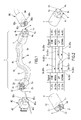
- Figure 1 shows a command inverter according to a first embodiment of the invention, indicated in general with reference numeral 1.
- the command inverter 1 comprises a first interface 2 for electrical connection to an electronic gearshifting control unit CPU ( Figure 5 ), a second interface 4 for electrical connection to a manual bicycle gearshift control device 30d, 30s ( Figure 5 ) mounted on the handlebars of the bicycle and a multiconductor cable 6 for electrical connection between the first interface 2 and the second interface 4.
- the first interface 2 of the command inverter 1 is formed in a first main body 3, preferably substantially cylindrical, in which a plurality of electrical terminations is housed.
- a first, a second, a third and a fourth electrical termination 2 G , 2 M , 2 U , 2 D suitable for electrically coupling in a removable manner with corresponding first, second, third and fourth matching electrical terminations, 80 G , 80 M , 80 U , 80 D , respectively, of a connector 80 associated with an interface I of the electronic control unit CPU ( Figure 5 ).
- the electrical terminations 2 G , 2 M , 2 U , 2 D are distributed in the first interface 2 of the command inverter 1 according to a univocal coupling configuration with the corresponding matching terminations 80 G , 80 M , 80 U , 80 D of the connector 80.
- each electrical termination 2 G , 2 M , 2 U , 2 D of the first interface 2 can be coupled only with the corresponding matching electrical termination 80 G , 80 M , 80 U , 80 D of the connector 80.
- the electrical terminations 2 G , 2 M , 2 U , 2 D are male electrical terminations and the matching and corresponding electrical terminations 80 G , 80 M , 80 U , 80 D are female electrical terminations, but of course, in a totally equivalent way, it is possible to provide female electrical terminations 2 G , 2 M , 2 U , 2 D and male electrical terminations 80 G , 80 M , 80 U , 80 D .
- the configuration shown may be preferable to avoid exposed male contacts on the electronic control unit CPU.
- the second interface 4 of the command inverter 1 comprises a main body 7, also preferably substantially cylindrical, in which a plurality of electrical terminations is housed.
- a first, a second, a third and a fourth electrical termination, 4 G , 4 M , 4 U , 4 D respectively, suitable for electrically coupling in a removable manner with corresponding matching first, second, third and fourth electrical terminations, 90 G , 90 M , 90 U , 90 D , respectively, of a connector 90 associated with the device 30d, 30s for actuating the gearshift of a bicycle ( Figure 5 ).
- the electrical terminations 4 G , 4 M , 4 U , 4 D are distributed on the second interface 4 according to a univocal coupling configuration with the corresponding matching terminations 90 G , 90 M , 90 U , 90 D of the connector 90.
- each electrical termination 4 G , 4 M , 4 U , 4 D of the second interface 4 can be coupled only with the corresponding electrical termination 90 G , 90 M , 90 U , 90 D of the connector 90.
- the electrical terminations 4 G , 4 M , 4 U , 4 D are female electrical terminations and the matching and corresponding electrical terminations 90 G , 90 M , 90 U , 90 D are male electrical terminations, but of course, in a totally equivalent way, it is possible to provide male electrical terminations 4 G , 4 M , 4 U , 4 D and female electrical terminations 90 G , 90 M , 90 U , 90 D .
- the univocal coupling between terminations 2 G , 2 M , 2 U , 2 D of the first interface and matching and corresponding terminations 80 G , 80 M , 80 U , 80 D of the connector 80 and between terminations 4 G , 4 M , 4 U , 4 D of the second interface and matching and corresponding terminations 90 G , 90 M , 90 U , 90 D of the connector 90 can be obtained by means of the geometrical arrangement, for example asymmetric as shown in Figure 1 , of the electrical terminations in the interfaces 2 and 4 and in the associated connectors 80 and 90, and/or by means of the asymmetric shape of the main bodies 3 and 7 of the command inverter 1 and/or of the connectors 80 and 90, shown in Figure 1 , and/or using a different colour for the different terminations and attributing the same colour to corresponding electrical terminations and/or with other identifying marks.
- connectors 80 and 90 have matching and corresponding terminations, 80 G , 80 M , 80 U , 80 D and 90 G , 90 M , 90 U , 90 D , respectively, which are suitable for univocally coupling when the command inverter 1 is not arranged between the gearshifting control device 30d, 30s and the electronic gearshifting control unit CPU of the bicycle.
- the main body 3 has an engagement element, for example a seat 12, suitable for cooperating with a corresponding engagement element, for example a tooth 82, provided in the connector 80 of the electronic gearshifting control unit CPU, to block the first interface 2 and the connector 80 in their connected configuration and contribute to define the univocity of coupling between interface and connector.
- an engagement element for example a seat 12
- a corresponding engagement element for example a tooth 82
- the main body 7 preferably has an engagement element, for example a tooth 14, suitable for cooperating with a corresponding engagement element, for example a seat 94, provided in the connector 90 to block the second interface 4 and the connector 90 in their connected configuration and contribute to define the univocity of coupling between interface and connector.
- an engagement element for example a tooth 14
- a corresponding engagement element for example a seat 94
- tooth and seat coupling elements have been illustrated, the present invention allows any mode of coupling that requires a minimal predetermined force to separate the command inverter 1 from the connectors 80 and 90.
- the terminations 2 G , 2 M , 2 U , 2 D of the first interface 2 and the terminations 4 G , 4 M , 4 U , 4 D of the second interface 4 are electrically connected together by means of the electrical multiconductor cable 6, comprising, in the illustrated embodiment, a first, a second, a third and a fourth conducting wire, 6 G , 6 M , 6 U , 6 D , respectively .
- Each conducting wire 6 G , 6 M , 6 U , 6 D can comprise a plurality of strands.
- each conducting wire 6 G , 6 M , 6 U , 6 D of the multiconductor cable 6 is coated by a respective first insulating sheath (not shown) and the conducting wires 6 G , 6 M , 6 U , 6 D thus coated are in turn wholly coated by an insulating sheath 16 to form the multiconductor cable 6.
- the first conducting wire 6 G connects together the first electrical termination 2 G of the first interface 2 and the first electrical termination 4 G of the second interface 4;
- the second conducting wire 6 M connects together the second electrical termination 2 M of the first interface 2 and the second electrical termination 4 M of the second interface 4;
- the third conducting wire 6 D connects together the fourth electrical termination 2 D of the first interface 2 and the third electrical termination 4 U of the second interface 4;
- the fourth conducting wire 6 U connects together the third electrical termination 2 U of the first interface 2 and the fourth electrical termination 4 D of the second interface 4.
- the first conducting wire 6 G is the earth conducting wire; in use, an electric MODE/SET signal s M for selecting an operating mode selected from normal travel, setting of gearshift parameters (MODE) and/or for selecting a value of the selected gearshift parameters (SET) between the control device 30d, 30s and the electronic control unit CPU ( Figure 5 ) travels along the second conducting wire 6 M ; in use, a signal s DR , s DF for controlling the downward gearshifting of the rear or front derailleur arriving from the right or left control device 30d, 30s and directed to the electronic control unit CPU ( Figure 5 ) travels along the third conducting wire 6 D ; and, in use, a control signal s UR , s UF of the upward gearshifting of the rear or front derailleur arriving from the right or left control device 30d, 30s and directed to the electronic control unit CPU ( Figure 5 ) travels along the fourth conducting wire 6 U .
- an electric MODE/SET signal s M for selecting an operating mode selected from normal travel, setting of
- the first and second conducting wire 6 G and 6 M of the multiconductor cable 6 electrically connect together matching and corresponding electrical terminations 2 G -4 G and 2 M -4 M of the first and second interface 2 and 4 of the command inverter 1.
- the third and fourth conducting wire 6 D and 6 U of the multiconductor cable 6 electrically connect together matching and not corresponding electrical terminations 2 D -4 U and 2 U -4 D of the first and second interface 2 and 4 of the command inverter 1. Therefore, the electrical terminations 2 D and 2 U of the first interface 2 are not electrically connected to matching and corresponding electrical terminations of the second interface 4.
- Figures 3 and 4 show a command inverter according to an alternative embodiment to that of Figure 1 .
- the command inverter comprises a container body 70, preferably substantially cylindrical, suitable for housing electrical terminations 20 G , 20 M , 20 U , 20 D and 40 G , 40 M , 40 U , 40 D , respectively, of a first interface 20 for electrical connection to an electronic gearshifting control unit CPU ( Figure 5 ) and of a second interface 40 for electrical connection to a manual control device 30d, 30s ( Figure 5 ) mounted on the handlebars of the bicycle.
- the first and second interface 20 and 40 are formed on opposite sides with respect to the container body 70.
- the first and second interface 20 and 40 are electrically connected through a plurality of conductive rods or foils, in particular a first, a second, a third and a fourth conductive rod, 60 G , 60 M , 60 U , 60 D , respectively, housed within the container body 70 and preferably co-moulded with the plastic material of the container body 70.
- the electrical terminations are directly formed at the ends of the rods.
- a plurality of electrical terminations 20 G , 20 M , 20 U , 20 D are present in the first interface 20 .
- a first, a second, a third and a fourth electrical termination 20 G , 20 M , 20 U , 20 D are provided, suitable for electrically coupling with corresponding matching electrical terminations 80 G , 80 M , 80 U , 80 D of the connector 80 ( Figure 1 ) associated with an interface I of the electronic control unit CPU ( Figure 5 ).
- the electrical terminations 20 G , 20 M , 20 U , 20 D are male electrical terminations distributed in the first interface 20 according to a univocal coupling configuration with corresponding female terminations 80 G , 80 M , 80 U , 80 D of the connector 80.
- each male electrical termination 20 G , 20 M , 20 U , 20 D of the first interface 20 can be coupled only with the corresponding female electrical termination 80 G , 80 M , 80 U , 80 D of the connector 80.
- the electrical terminations 20 G , 20 M , 20 U , 20 D of the first interface 20 can be female electrical terminations suitable for electrically coupling with corresponding male electrical terminations 80 G , 80 M , 80 U , 80 D of the connector 80.
- a plurality of electrical terminations are present.
- a first, a second, a third and a fourth electrical termination 40 G , 40 M , 40 U , 40 D are provided suitable for electrically coupling with corresponding matching electrical terminations 90 G , 90 M , 90 U , 90 D of the connector 90 ( Figure 1 ) associated with a control device 30d, 30s ( Figure 5 ).
- the electrical terminations 40 G , 40 M , 40 U , 40 D are female electrical terminations distributed in the second interface 40 according to a univocal coupling configuration with corresponding male terminations 90 G , 90 M , 90 U , 90 D of the connector 90.
- each female electrical termination 40 G , 40 M , 40 U , 40 D of the first interface 40 can be coupled only with the corresponding male electrical termination 90 G , 90 M , 90 U , 90 D of the connector 90.
- the electrical terminations 40 G , 40 M , 40 U , 40 D of the second interface 40 can be male electrical terminations suitable for electrically coupling with corresponding female electrical terminations 90 G , 90 M , 90 U , 90 D of the connector 90.
- the univocal coupling between terminations 20 G , 20 M , 20 U , 20 D of the first interface and the matching and corresponding terminations 80 G , 80 M , 80 U , 80 D of the connector 80 and between terminations 40 G , 40 M , 40 U , 40 D of the second interface 40 and the matching and corresponding terminations 90 G , 90 M , 90 U , 90 D of the connector 90 can be obtained by the geometric arrangement, for example asymmetric as shown in Figures 3 and 4 , of the electrical terminations in the interfaces 20 and 40 and in the associated connectors 80 and 90, and/or by the asymmetric shape of the interfaces 20 and 40 of the command inverter 1 and of the connectors 80 and 90, shown in Figure 1 , and/or by using a different colour and/or mark for the different terminations and attributing the same colour and/or mark to corresponding electrical terminations.
- the container body 70 has an engagement element, for example a seat 22, suitable for cooperating with the tooth 82 ( Figure 1 ) of the connector 80 to block the first interface 20 and the connector 80 in their connected configuration and contribute to defining the univocity of coupling between the command inverter 10 and the connector 80.
- an engagement element for example a seat 22 suitable for cooperating with the tooth 82 ( Figure 1 ) of the connector 80 to block the first interface 20 and the connector 80 in their connected configuration and contribute to defining the univocity of coupling between the command inverter 10 and the connector 80.
- the container body 70 preferably has an engagement element, for example a tooth 44, suitable for cooperating with the seat 94 ( Figure 1 ) of the connector 90 to block the second interface 40 and the connector 90 in their connected configuration and contribute to the univocity of coupling between the command inverter 10 and the connector 90.
- an engagement element for example a tooth 44
- the first conductive rod 60 G connects together the first electrical termination 20 G of the first interface 20 and the first electrical termination 40 G of the second interface 40;
- the second conductive rod 60 M connects together the second electrical termination 20 M of the first interface 20 and the second electrical termination 40 M of the second interface 40;
- the third conductive rod 60 D connects together the fourth electrical termination 20 D of the first interface 20 and the third electrical termination 40 U of the second interface 40;
- the fourth conductive rod 60 U connects together the third electrical termination 20 U of the first interface 20 and the fourth electrical termination 40 D of the second interface 40.
- the first conductive rod 60 G is the earth rod; in use, an electric MODE/SET signal s M between the control device 30d, 30s and the electronic control unit CPU ( Figure 5 ) travels along the second conductive rod 60 M ; in use, a signal s DR , s DF for controlling the downward gearshifting of the rear or front derailleur arriving from the right or left control device 30d, 30s and directed to the electronic control unit CPU ( Figure 5 ) travels along the third conductive rod 60 D ; and, in use, an electric signal s UR , s UF for controlling the upward gearshifting of the rear or front derailleur arriving from the right or left control device 30d, 30s and directed to the electronic control unit CPU ( Figure 5 ) travels along the fourth conductive rod 60 U .
- the conductive rods 60 G and 60 M electrically connect together matching and corresponding electrical terminations 20 G -40 G and 20 M -40 M of the first and second interface 20 and 40 of the command inverter 10.
- the conductive rods 60 D and 60 U connect together matching and not corresponding electrical terminations 20 D -40 U and 20 U -40 D of the first and second interface 20 and 40 of the command inverter 10. Therefore, the electrical terminations 20 D and 20 U of the first interface 20 are not electrically connected to matching and corresponding electrical terminations of the second interface 40.
- the right control device 30d is suitable for controlling upward and downward gearshifting of the rear derailleur of the bicycle
- the left control device 30s is suitable for controlling upward and downward gearshifting of the front derailleur of the bicycle.
- Each control device 30d, 30s comprises an assembly portion 32d and 32s suitable for being mounted at the end of handlebars for bar-end controls facing forwards in the travel direction of the bicycle, a control lever 34d and 34s projecting forwards from the assembly portion of the control device in the travel direction of the bicycle and electrical actuation means, typically a pair of switches (not shown) and a connector 90 for connecting to an electronic gearshifting control unit CPU, the connector being mounted at the end of a multiconductor cable 36d, 36s.
- each control device 30d, 30s can also provide a switch (not shown) for so-called MODE command, controlled by a lever or by a button (not shown), for selecting an operating mode selected from normal travel, setting of gearshift parameters etc, and/or a switch for so-called SET command for selecting a value of the selected gearshift parameters.
- a switch for so-called MODE command, controlled by a lever or by a button (not shown), for selecting an operating mode selected from normal travel, setting of gearshift parameters etc, and/or a switch for so-called SET command for selecting a value of the selected gearshift parameters.
- the electronic gearshifting control unit CPU comprises an interface I, in electrical connection with the switches of the control devices 30d, 30s mounted on the right and left of the handlebars, and a power system SP in electrical connection with the interface I.
- the interface I is suitable for receiving upward and downward gearshifting control signals imparted through the switches of the pair of control devices 30d, 30s and for transmitting them to the power system SP that, as a function of the gearshifting control signal received, actuates a respective actuator A R and A F of the rear and/or front derailleur so as to move the motion transmission chain on the toothed wheels associated with the axle of the pedal cranks and with the hub of the rear wheel, so as to establish the transmission ratio selected by the cyclist, thus performing a gearshifting.
- Each control device 30d, 30s is connected by means of the connector 90 of the electrical multiconductor cable 36d, 36s to a respective command inverter 1 by coupling the connector 90 with the respective second interface 4 of the command inverter 1.
- the first interface 2 of each command inverter 1 is, on the other hand, connected to a respective connector 80 of the interface I of the electronic gearshifting control unit CPU.
- the signal s UR is an upward gearshifting signal of the rear derailleur. Indeed, following the scheme of electrical connection between the first and the second interface 2 and 4 illustrated in Figure 2 , the signal s UR transits from the electrical termination 4 D of the second interface 4 to the electrical termination 2 U of the first interface 2 of the command inverter 1, travelling along the electric wire 6 U of the multiconductor cable 6 of the command inverter 1, and from this to the electrical termination 80 U of the connector 80 of the interface I.
- the signal s DR is a downward gearshifting signal of the rear derailleur. Indeed, following the scheme of electrical connection between the first and the second interface 2 and 4 illustrated in Figure 2 , the signal s DR transits from the electrical termination 4 U of the second interface 4 to the electrical termination 2 D of the first interface 2 of the command inverter 1, travelling along the electric wire 6 D of the multiconductor cable 6 of the command inverter 1, and from this to the electrical termination 80 D of the connector 80 of the interface I, associated indeed with the entry of a downward gearshifting signal.
- a signal s UF is transmitted to the command inverter 1.
- Such a signal s UF enters the command inverter 1 at the electrical termination 4 D of the second interface 4, passes through the conducting wire 6 U and comes out from the command inverter 1 at the electrical termination 2 U of the first interface 2.
- the interface I of the electronic control unit CPU receives the signal s UF at the correct electrical termination 80 U so that it transmits an upward gearshifting signal to the power system SP, as desired.
- the power system SP thus makes the actuator A F of the front derailleur move so that it moves the chain onto a toothed wheel of greater diameter, thus performing an upward gearshifting of the front derailleur.
- a signal s DF is transmitted to the command inverter 1.
- a signal s DF enters the command inverter 1 at the electrical termination 4 U of the second interface 4, passes through the conducting wire 6 D and comes out from the command inverter 1 at the electrical termination 2 D of the first interface 2.
- the interface I of the electronic control unit CPU receives the signal s DF at its electrical termination 80 D so that it transmits a downward gearshifting signal to the power system SP.
- the power system SP actuates the actuator A F of the front derailleur so that it moves the chain onto a toothed wheel of smaller diameter, thus performing a downward gearshifting of the front derailleur.
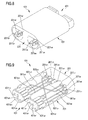
- Figure 6 shows a command inverter according to a third embodiment of the invention, indicated in general with reference numeral 100.
- the command inverter 100 comprises a first interface 200 for electrical connection to an electronic gearshifting control unit CPU ( Figure 10 ), a second interface 400 for electrical connection to a pair of gearshift control devices 30d, 30s ( Figure 10 ) of a bicycle mounted on the handlebars of the bicycle and a branched multiconductor cable 600 R , 600 U for electrical connection between the first interface 200 and the second interface 400.
- the command inverter 100 comprises a first main body 300 in which the plurality of electrical terminations of the first interface 200 is housed.
- a first, a second, a third, a fourth, a fifth, a sixth, a seventh and an eighth electrical termination 200 GR , 200 MR , 200 UR , 200 DR , 200 GF , 200 MF , 200 UF , 200 DF are provided, which are suitable for electrically coupling with corresponding first, second, third, fourth, fifth, sixth, seventh and eighth matching electrical terminations 800 GR , 800 MR , 800 UR , 800 DR , 800 GF , 800 MF , 800 UF , 800 DF of connectors 800 R , 800 F associated with an interface I of the electronic control unit CPU ( Figure 10 ).
- the male electrical terminations 200 GR , 200 MR , 200 UR , 200 DR , 200 GF , 200 MF , 200 UF , 200 DF are distributed in the first interface 200 of the command inverter 100 according to a univocal coupling configuration with the corresponding female terminations 800 GR , 800 MR , 800 UR , 800 DR , 800 GF , 800 MF , 800 UF , 800 DF of connectors 800 R , 800 F .
- each male electrical termination 200 GR , 200 MR , 200 UR , 200 DR , 200 GF , 200 MF , 200 UF , 200 DF of the first interface 200 can be coupled only with the corresponding female electrical termination 800 GR , 800 MR , 800 UR , 800 DR , 800 GF , 800 MF , 800 UF , 800 DF of connectors 800 R , 800 F .
- the electrical terminations 200 GR , 200 MR , 200 UR , 200 DR , 200 GF , 200 MF , 200 UF , 200 DF of the first interface 200 are male electrical terminations and the matching and corresponding electrical terminations 800 GR , 800 MR , 800 UR , 800 DR , 800 GF , 800 MF , 800 UF , 800 DF of connectors 800 R , 800 F are female electrical terminations.
- female electrical terminations 200 GR , 200 MR , 200 UR , 200 DR , 200 GF , 200 MF , 200 UF , 200 DF and male electrical terminations 800 GR , 800 MR , 800 UR , 800 DR , 800 GF , 800 MF , 800 UF , 800 DF can be provided.
- the command inverter 100 comprises a second and a third main body 700 R , 700 F , preferably substantially cylindrical.
- a first, a second, a third and a fourth electrical termination 400 GR , 400 MR , 400 UR , 400 DR are housed, suitable for electrically coupling with corresponding first, second, third and fourth matching electrical terminations 900 GR , 900 MR , 900 UR , 900 DR , of a connector 900 R associated with the manual gearshift control device 30d of a bicycle mounted on the right of the handlebars ( Figure 10 ).
- a fifth, a sixth, a seventh and an eighth electrical termination 400 GF , 400 MF , 400 UF , 400 DF are housed, which are suitable for electrically coupling with corresponding matching electrical terminations 900 GF , 900 MF , 900 UF , 900 DF of a connector 900 F associated with the gearshift control device 30s of a bicycle mounted on the right of the handlebars ( Figure 10 ).
- the electrical terminations 400 GR , 400 MR , 400 UR , 400 DR , 400 GF , 400 MF , 400 UF , 400 DF of the second interface 400 are distributed in the second and third body 700 R , 700 F of the command inverter 100 according to a univocal coupling configuration with the corresponding terminations 900 GR , 900 MR , 900 UR , 900 DR , 900 GF , 900 MF , 900 UF , 900 DF of connectors 900 R , 900 F .
- each electrical termination 400 GR , 400 MR , 400 UR , 400 DR , 400 GF , 400 MF , 400 UF , 400 DF of the second interface 400 can be coupled only with the corresponding electrical termination 900 GR , 900 MR , 900 UR , 900 DR , 900 GF , 900 MF , 900 UF , 900 DF of connectors 900 R , 900 F .
- the electrical terminations 400 GR , 400 MR , 400 UR , 400 DR , 400 GF , 400 MF , 400 UF , 400 DF of the second interface 400 are female electrical terminations and the matching and corresponding electrical terminations 900 GR , 900 MR , 900 UR , 900 DR , 900 GF , 900 MF , 900 UF , 900 DF of connectors 900 R , 900 F are male electrical terminations.
- the univocal coupling between the electrical terminations 200 GR , 200 MR , 200 UR , 200 DR , 200 GF , 200 MF , 200 UF , 200 DF of the first interface 200 and the matching and corresponding electrical terminations 800 GR , 800 MR , 800 UR , 800 DR , 800 GF , 800 MF , 800 UF , 800 DF of connectors 800 R , 800 F and between the electrical terminations 400 GR , 400 MR , 400 UR , 400 DR , 400 GF , 400 MF , 400 UF , 400 DF of the second interface 400 and the matching and corresponding electrical terminations 900 GR , 900 MR , 900 UR , 900 DR , 900 GF , 900 MF , 900 UF , 900 DF of connectors 900 R , 900 F can be obtained by the geometric arrangement, for example asymmetrical as shown in Figure 6 , of the electrical terminations in the
- the connectors 800 R , 800 F and 900 R , 900 F have matching and corresponding terminations, 800 GR , 800 MR , 800 UR , 800 DR , 800 GF , 800 MF , 800 UF , 800 DF and 900 GR , 900 MR , 900 UR , 900 DR , 900 GF , 900 MF , 900 UF , 900 DF , respectively, which are suitable for coupling univocally when the command inverter 100 is not arranged between the gearshifting control device 30d, 30s and the electronic gearshifting control unit CPU of the bicycle.
- the electrical terminations 200 GR , 200 MR , 200 UR , 200 DR , 200 GF , 200 MF , 200 UF , 200 DF of the first interface 200 and the terminations 400 GR , 400 MR , 400 UR , 400 DR , 400 GF , 400 MF , 400 UF , 400 DF of the second interface 400 are electrically connected together by means of the multiconductor cable 600 having two branches 600 R , 600 F , each comprising, for example, four conducting wires, 600 GR , 600 MR , 600 UR , 600 UF and 600 GF , 600 MF , 600 DF , 600 DR , respectively.
- Each conducting wire 600 GR , 600 MR , 600 UR , 600 DR , 600 GF , 600 MF , 600 UF , 600 DF can comprise a plurality of strands.
- each conducting wire 600 GR , 600 MR , 600 UR , 600 DR , 600 GF , 600 MF , 600 UF , 600 DF of the multiconductor cable having two branches 600 is coated by a respective first insulating sheath (not shown) and the conducting wires thus coated are in turn wholly coated by a common insulating sheath 616, which follows the branching of the conductive cable 600.
- the first conducting wire 600 GR connects together the first electrical termination 200 GR of the first interface 200 and the first electrical termination 400 GR of the second interface 400;
- the second conducting wire 600 MR connects together the second electrical termination 200 MR of the first interface 200 and the second electrical termination 400 MR of the second interface 400;
- the third conducting wire 600 UR connects together the third electrical termination 200 UR of the first interface 200 and the third electrical termination 400 UR of the second interface 400;
- the fourth conducting wire 600 DR connects together the fourth electrical termination 200 DR of the first interface 200 and the seventh electrical termination 400 UF of the second interface 400;
- the fifth conducting wire 600 GF connects together the fifth electrical termination 200 GF of the first interface 200 and the fifth electrical termination 400 GF of the second interface 400;
- the sixth conducting wire 600 MF connects together the sixth electrical termination 200 MF of the first interface 200 and the sixth electrical termination 400 MR of the second interface 400;
- the seventh conducting wire 600 UF connects together the seventh electrical termination 200 UF of the first interface 200 and the fourth electrical
- the first conducting wire 600 GR is the earth conducting wire associated with the right control device 30d; in use, an electric MODE/SET signal s MR between the right control device 30d and the electronic control unit CPU ( Figure 10 ) travels along the second conducting wire 600 MR ; in use, an electric signal s UR for commanding upward gearshifting of the rear derailleur arriving from the right control device 30d and directed to the electronic control unit CPU ( Figure 10 ) travels along the third conducting wire 600 UR ; in use, an electric signal s DR for commanding downward gearshifting of the rear derailleur arriving from the left control device 30s and directed to the electronic control unit CPU ( Figure 10 ) travels along the fourth conducting wire 600 DR ; the fifth conducting wire 600 GF is the earth conducting wire associated with the left control device 30s; in use, an electric MODE/SET signal s MF between the left control device 30s and the electronic control unit CPU ( Figure 10 ) travels along the sixth conducting wire 600 MF ; in use, an electric signal s UF for command
- the conducting wires 600 GR , 600 MR , 600 UR and 600 GF , 600 MF , 600 DF electrically connect together matching and corresponding electrical terminations 200 GR -400 GR , 200 MR -400 MR , 200 UR -400 UR , 200 GF -400 GF , 200 MF -400 MF , 200 DF -400 DF of the first and second interface 200 and 400 of the command inverter 100.
- the conducting wires 600 UF and 600 DR connect together not corresponding electrical terminations 200 UF -400 DR and 200 DR -400 UF of the first and second interface 200 and 400 of the command inverter 100. Therefore, the electrical terminations 200 UF and 200 DR of the first interface 200 are not electrically connected to matching and corresponding electrical terminations of the second interface 400.
- a cyclist by lifting the lever of the right gearshift control device 30d commands the upward gearshifting of the rear derailleur and by lowering the lever of the same right control device 30d commands the upward gearshifting of the front derailleur.
- a cyclist by lifting the lever of the left gearshift control device 30s commands the downward gearshifting of the rear derailleur and by lowering the lever of the same left control device 30s, commands the downward gearshifting of the front derailleur.
- the cyclist commands upward and downward gearshifting, respectively, of both of the deraille, front and rear.
- FIGS 8 and 9 illustrate a command inverter according to a fourth embodiment of the invention of Figures 6 and 7 .
- the command inverter 101 differs from the command inverter 100 in that it has a container body 701 in which the electrical terminations of a first interface 201 for electrical connection with the electronic gearshifting control unit CPU and of a second interface 401 for electrical connection with a pair of gearshift control devices 30d, 30s mounted on the right and left of the handlebars of the bicycle are housed and in that the multiconductor cable 600 having two branches 600 D , 600 R is replaced by a plurality of conductive rods or foils 601 GR , 601 MR , 601 UR , 601 DR , 601 GF , 601 MF , 601 UF , 601 DF , similarly to the embodiment of Figures 3 and 4 to which we refer.
- the first interface 201 comprises a first, a second, a third, a fourth, a fifth, a sixth, a seventh and an eighth male electrical termination, 201 GR , 201 MR , 201 UR , 201 DR , 201 GF , 201 MF , 201 UF , 201 DF , respectively, suitable for electrically coupling with respective female electrical terminations of connectors 800 R , 800 F associated with the interface I of the electronic control unit CPU ( Figure 10 ).
- the second interface 401 comprises a first, a second, a third and a fourth female electrical termination 401 GR , 401 MR , 401 UR , 401 DR suitable for electrically coupling with respective male electrical terminations 900 GR , 900 MR , 900 UR , 900 DR of the connector 900 R associated with the right control device 30d ( Figure 10 ) and a fifth, a sixth, a seventh and an eighth female electrical termination 401 GF , 401 MF , 401 UF , 401 DF suitable for electrically coupling with respective male electrical terminations 900 GF , 900 MF , 900 UF , 900 DF of the connector 900 D associated with the left control device 30s ( Figure 10 ).
- the command inverter all of the possible variants outlined earlier with reference to the command inverter 100 of Figure 6 are valid.
- connections between the electrical terminations of the first interface 201 and the electrical terminations of the second interface 401, as well as the mode of connection between the electrical terminations of the first interface 201 and the electrical terminations of connectors 800 R , 800 F and the mode of connection between the electrical terminations of the second interface 401 and the electrical terminations of connectors 900 R , 900 F are totally similar to those described for the command inverter 100 with reference to Figure 7 , but they are made through the rods 601 GR , 601 MR , 601 UR , 601 DR , 601 GF , 601 MF , 601 UF , 601 DF instead of wires of a multiconductor cable.
- the right control device 30d is suitable for commanding upward and downward gearshifting of the rear derailleur
- the left control device 30s is suitable for commanding upward and downward gearshifting of the front derailleur.
- Each control device 30d and 30s is connected through an electrical multiconductor cable 36d and 36s equipped with the connector 900 R , 900 F to the command inverter 100 by coupling the connector 900 R , 900 F to the second interface 400 of the inverter 100. More specifically, the connector 900 R is coupled with the main body 700 R and the connector 900 F is coupled with the main body 700 F .
- the first interface 200 of the command inverter 100 is connected to the connectors 800 R , 800 F of the interface I of the electronic control unit CPU.
- the signal s UR transits from the electric terminal 400 UR of the second interface 400 to the electric terminal 200 UR of the first interface 200 of the command inverter 100 travelling along the electric wire 600 UR of the command inverter 100 and from this to the electric terminal 800 UR of the connector 800 R of the interface I.
- the interface I transmits the signal s UR to the power system SP and the power system SP thus makes the actuator A R of the rear derailleur move so that it moves the chain onto a toothed wheel of greater diameter, thus performing an upward gearshifting of the rear derailleur.
- the signal s UF is an upward gearshifting signal of the front derailleur. Indeed, again following the scheme of electrical connection between the first and the second interface 200 and 400 illustrated in Figure 7 , the signal s UF transits from the electric terminal 400 DR of the second interface 400 to the electric terminal 200 UF of the first interface 200 of the command inverter 100 travelling along the electric wire 600 UF of the command inverter 100 and from this to the electric terminal 800 UF of the connector 800 F connected to the interface I.
- a downward gearshifting signal s DF of the front derailleur is generated that, through the multiconductor cable 36s reaches the electrical termination 900 DF of the connector 900 F and from this the electrical termination 400 DF of the second interface 400 of the command inverter 100.
- the signal s DF transits from the electric terminal 400 DF of the second interface 400 to the electric terminal 200 DF of the first interface 200 of the command inverter 100 travelling along the electric wire 600 DF of the command inverter 100 and from this to the electric terminal 800 DF of the connector 800 F of the interface I.
- the interface I transmits the signal s DF to the power system SP, which makes the actuator A F of the front derailleur move so that it moves the chain onto a toothed wheel of smaller diameter, thus performing downward gearshifting of the front derailleur.
- the signal s DR is a downward gearshifting signal of the rear derailleur. Indeed, again following the scheme of electrical connection between the first and the second interface 200 and 400 illustrated in Figure 7 , the electric downward gearshifting signal s DR transits from the electric terminal 400 UF of the second interface 400 to the electric terminal 200 DR of the first interface 200 of the command inverter 100 travelling along the electric wire 600 DR of the command inverter 100 and from this to the electric terminal 800 DR of the connector 800 R connected to the interface I.
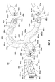
- Figure 11 shows a command inverter according to a fifth embodiment, indicated in general with reference numeral 102, and the mode of electrical connection thereof between a pair of right and left gearshift control devices 30d, 30s and the electronic gearshifting control unit CPU.
- the command inverter 102 comprises a first interface 202 for electrical connection to the electronic gearshifting control unit CPU and a second interface 402 for electrical connection with a pair of gearshift control devices 30d, 30s mounted on the right and left of the handlebars of the bicycle.
- the second interface 402 is totally similar to the second interface 400 of the command inverter 100 of Figure 6 and comprises a first main body 402 R and a second main body 402 F for coupling, respectively, with connectors 900 R and 900 F of the right and left gearshift control devices 30d and 30s.
- the first interface 202 differs from the first interface 200 of the command inverter 100 in that it comprises a first main body 202 R and a second main body 202 F for coupling with connectors 800 D and 800 R of the interface I of the electronic gearshifting control unit CPU.
- connections between the electrical terminations of the first interface 202 and connectors 800 R , 800 F and connections between the electrical terminations of the second interface 402 and connectors 900 R , 900 F of the right and left control devices 30d, 30s are totally similar to those described for the command inverter 100, and thus they will not be further illustrated.
- a printed circuit board 606 is arranged, comprising a plurality of tracks (not shown), which acts as a means of electrical connection between the first interface and the second interface 202 and 402 of the command inverter 102.
- the printed circuit board 606 is connected to the first interface 202 of the command inverter 102 by means of a first pair of multiconductor cables 620 R and 620 F , each equipped with a respective connector 622 F and 622 R for electrical connection to the printed circuit board 606.
- the printed circuit board 606 is also connected to the second interface 402 of the command inverter 202 by means of a second pair of multiconductor cables 640 R , 640 F , each equipped with a respective connector 642 F and 642 R for electrical connection to the printed circuit board 606.
- the arrangement of tracks inside the printed circuit board 606 is such as to make the inversion of the commands according to the connection scheme of Figure 7 .
- the command inverter device of the various illustrated embodiments an inversion is carried out between the commands of a pair of commands or of two pairs of commands
- the inverted/modified commands can comprise, as an alternative or in addition, also one or more MODE/SET commands.
- control inverters of the invention are equally applicable to any type of gearshift, like for example a semi-automatic gearshift and, as stated above, also to controls not of the bar-end type.
- gearshift like for example a semi-automatic gearshift
- gearshift control devices like for example a gearshift and, as stated above, also to controls not of the bar-end type.
- a mode of connection through removable connectors between the command inverter and the electronic gearshifting control unit, on the one hand, and one or two gearshift control devices, on the other hand has been described and illustrated, it is possible to provide any similar mode of connection, within the capabilities of the man skilled in the art.
- the male electrical terminations do not necessarily have to be made projecting inside cavities of the main bodies as shown.
- the connectors shown as directly associated with the CPU and with the controls can, on the other hand, be made at the end of respective cables removably connected to the CPU and to the controls, for example to facilitate the assembly of the various parts of the gearshift on the frame of the bicycle.
- the command inverter is applicable to a single control device suitable for imparting control signals of the change of the transmission ratio, suitably converted by the CPU into upward and/or downward gearshifting signals of one or both of the derailleur.
- the command inverter is applicable to gearshifts having just the rear derailleur or just the front derailleur.
- the command inverter of Figures 1-5 can thus be commercialised by itself or in a kit of two inverters; in the kit one or two controls can also be present; the command inverter of Figures 6-11 can be commercialised in a kit with two controls.
Landscapes
- Engineering & Computer Science (AREA)
- Mechanical Engineering (AREA)
- Chemical & Material Sciences (AREA)
- Combustion & Propulsion (AREA)
- Transportation (AREA)
- Electric Propulsion And Braking For Vehicles (AREA)
Abstract
- a first interface (2) with an electronic gearshifting control unit (CPU), said first interface (2) comprising a plurality of electrical terminations (2G, 2M, 2U, 2D);
- a second interface (4) with said at least one gearshift control device (30d, 30s), said second interface (4) comprising a plurality of electrical terminations (4G, 4M, 4U, 4D) matching with and corresponding to the electrical terminations (2G, 2M, 2U, 2D) of the first interface (2);
wherein at least one electrical termination (2U, 2D) of the first interface (2) is not electrically connected to a corresponding electrical termination (4U, 4D) of the second interface (4).
Description
- The present invention refers, in general, to the technical field of manual bicycle gearshift control devices. More specifically, the present invention refers to a command inverter for a manual bicycle gearshift control device of the bar-end type.
- A motion transmission system in a bicycle comprises a chain extended between toothed wheels associated with the axle of the pedal cranks and with the hub of the rear wheel. When there is more than one toothed wheel at at least one between the axle of the pedal cranks and the hub of the rear wheel, and the motion transmission system is therefore equipped with a gearshift, a front derailleur and/or a rear derailleur is provided. In the case of an electronically servo-assisted gearshift, each derailleur comprises a chain guide element, also known as cage plate, which is movable to move the chain between the toothed wheels in order to vary the transmission ratio, and an electromechanical actuator to move the chain guide element. Typically, the actuator in turn comprises a motor, typically an electric motor, coupled with the chain guide element by means of a linkage such as an articulated parallelogram, a rack system or a worm screw system, as well as a position, speed and/or acceleration sensor of the rotor or of any mobile part downstream of the rotor, up to the chain guide element itself. It is worth emphasising that slightly different terminology from that used in this context is also in use.
- A control electronics varies the transmission ratio based on commands manually entered by the cyclist by mean of suitable control devices, for example a lever and/or buttons and/or based on automatically entered commands or, as far as the invention is concerned, semi-automatically entered commands. In case of automatically or semi-automatically entered commands, the control electronics establishes - typically based on the outputs of sensors of the travel parameters - such as the travel speed, the rotation speed of the pedal cranks, the slope of the travel ground, the heart rate of the cyclist and similar - when it is suitable to change transmission ratio and automatically generates signals requesting movement of the derailleur (automatic operation) or performs a supervision/integration of the cyclist's requests, preventing them, bypassing them, delaying them and/or integrating them with automatically generated requests, or vice-versa proposing such requests to the cyclist that in any case has the option of bypassing them (semi-automatic operation).
- It is well known that for bicycles intended for racing there is a constant search for solutions to improve performance. In particular, for bicycles intended for speed races, such as typically time trials, a good aerodynamic configuration of all of the bicycle components is particularly important. Moreover, a factor for improving performance is considered to be the efficiency of all of the controls, but also how safe and easy they are to actuate, in that the cyclist is able to concentrate on the physical effort without obstacles due to difficulties in actuating the controls.
- Recently, specialised handlebars for speed races have become popular, which have two or four bars or ends facing markedly forwards, which allow the cyclist to maintain a position of the torso greatly inclined forwards, which is aerodynamically efficient.
- With these handlebars, specific control devices have also become well-established, both for the brakes and for the gearshift; these devices are commonly called bar-end devices since they are housed right at the ends of the handlebars, so that the cyclist can actuate them easily without having to change his position.
- As mentioned before, manual bicycle gearshift control devices of the bar-end types comprise lever control devices and button control devices.
- A lever-operated manual control device of the bar-end type comprises an assembly portion suitable for being mounted at the end of a handlebars facing forwards in the travel direction of the bicycle, a control lever projecting forwards from the assembly portion of the manual control device in the travel direction of the bicycle and means for imparting at least one control signal, typically comprising a pair of switches actuated by the lever. The control signals are transmitted to an electronic gearshifting control unit through a multiconductor cable.
- Typically, the lever is angularly mobile with respect to the assembly portion between an intermediate neutral position, in which no gearshifting is commanded, and two operative positions, typically a raised operative position, in which an upward gearshifting is commanded, i.e. a movement of the chain, carried out by the rear or front derailleur, respectively, onto a toothed wheel of greater diameter with respect to the one currently engaged by the chain, and a lowered operative position, in which a downward gearshifting is commanded, i.e. a movement of the chain, carried out by the rear or front derailleur, respectively, onto a toothed wheel of smaller diameter with respect to the one currently engaged by the chain.
- A button-operated manual control device of the bar-end type comprises an assembly portion suitable for being mounted at the end of the handlebars, a pair of buttons projecting from the assembly portion and means for imparting an electrical control signal, typically comprising a pair of switches actuated by the buttons. Also in this case, signals are transmitted to an electronic gearshifting control unit through a multiconductor cable. In particular, by acting on the upper button, the cyclist commands an upward gearshifting and by acting on the side button he commands a downward gearshifting.
- It is also possible to use the lever/button to impart a command to change a transmission ratio, the electronic control unit providing for transforming the command into a gearshifting command of the rear and/or front derailleur.
- Both with the lever-operated manual control device and with the button-operated manual control device, the electronic gearshifting control unit comprises an interface, in electrical connection with the switches of the control devices mounted on the right and left of the handlebars, and a power system in electrical connection with the interface. The interface is suitable for receiving, through the multiconductor cable, upward and downward gearshifting control signals imparted by the switches of the pair of gearshift control devices and for transmitting them to the power system that, as a function of the gearshifting control signal received, actuates the respective actuator of the rear and/or front wheel, so as to move the motion transmission chain on the toothed wheels associated with the axle of the pedal cranks and with the hub of the rear wheel, so as to establish the transmission ratio selected by the cyclist, thus carrying out the gearshifting.
- Both with the lever-operated manual control device and with the button-operated manual control device it is possible to provide other switches, for example a switch for a so-called MODE command, operated by a lever or by a button, for selecting an operating mode selected from normal travel, setting of gearshift parameters etc., and/or a switch for a so-called SET command, for selecting a value of the selected gearshift parameters.
- In the typical configuration (hereafter "standard") of a handlebars equipped with manual bicycle gearshift control devices of the bar-end type, the right device controls upward and downward gearshifting in the rear derailleur, whereas the left device controls upward and downward gearshifting in the front derailleur.
- If a cyclist wishes to perform an upward gearshifting of the rear derailleur, he must lift the lever, or correspondingly press the upper button, of the manual gearshift control device mounted on the right of the handlebars, thus activating the respective switch. An upward gearshifting signal of the rear derailleur is thus generated, which is transmitted, through the multi-conductor cable, to the interface and from this to the power system of the electronic gearshifting control unit. The power system, in turn, actuates the actuator of the rear derailleur so as to move the chain onto a toothed wheel of greater diameter among the toothed wheels associated with the hub of the rear wheel.
- Differently, if a cyclist wishes to perform a downward gearshifting of the rear derailleur, he must lower the lever, or correspondingly press the side button, of the manual gearshift control device mounted on the right of the handlebars, thus activating the respective switch. A downward gearshifting signal of the rear derailleur is thus generated, which is transmitted, through the multi-conductor cable, to the interface and from this to the power system of the electronic gearshifting control unit. The power system, in turn, actuates the actuator of the rear derailleur so as to move the chain onto a toothed wheel of smaller diameter.
- Similarly, if a cyclist wishes to perform an upward gearshifting of the front derailleur, he must lift the lever, or correspondingly press the upper button, of the manual gearshift control device mounted on the left of the handlebars, thus activating the respective switch. An upward gearshifting signal of the front derailleur is thus generated, which is transmitted, through the multi-conductor cable, to the interface and from this to the power system of the electronic gearshifting control unit. The power system, in turn, actuates the actuator of the front derailleur so as to move the chain onto a toothed wheel of greater diameter among the toothed wheels associated with the axle of the pedal cranks.
- Finally, if a cyclist wishes to perform a downward gearshifting of the front derailleur, he must lower the lever, or correspondingly press the side button, of the manual gearshift control device mounted on the left of the handlebars, thus activating the respective switch. A downward gearshifting signal of the front derailleur is thus generated, which is transmitted, through the multi-conductor cable, to the interface and from this to the power system of the electronic gearshifting control unit. The power system, in turn, actuates the actuator of the front derailleur so as to move the chain onto a toothed wheel of smaller diameter.
- The Applicant has now realised that a cyclist could wish to have inverted gearshifting commands, due to personal preference, due to physical characteristics, for example left or right-handed cyclist, and/or due to particular requirements, for example associated with riding style, in particular with the aerodynamic position taken up during a time trial in the case of gearshift control devices of the bar-end type.
- More specifically, a cyclist could wish to command upward gearshifting by lowering, instead of lifting, the lever, or by pressing the side button, instead of the upper button, of the manual gearshift control device and to command downward gearshifting by lifting, instead of lowering, the lever, or by pressing the upper button, instead of the side button, of the manual gearshift control device.
- Furthermore, the cyclist could wish to use the manual gearshift control device, operated by a lever or buttons, mounted on the right of the handlebars to command upward gearshifting both of the front derailleur and of the rear derailleur and to use the manual gearshift control device, operated by a lever or buttons, mounted on the left of the handlebars to command downward gearshifting both of the front derailleur and of the rear derailleur, or vice-versa.
- Furthermore, other configurations of inversion or variation of the controls may be desirable, for example inversions between the upward and/or downward gearshifting controls and the MODE and/or SET commands defined above.
- Also in the case of a control device not of the bar-end type, the cyclist could have a reason to wish to vary the gearshifting commands imparted with each lever/button.
- The technical problem forming the basis of the present invention is, therefore, to allow the cyclist to personalise the generation, by means of manual control devices, of upward and downward gearshifting controls of the rear and/or front derailleur of the bicycle based on his preferences and/or needs, thus ensuring a high versatility in use of the control devices themselves.
- Therefore, in a first aspect thereof, the present invention relates to a command inverter according to
claim 1; preferred characteristics are given in the dependent claims. The invention also relates to a kit of parts comprising at least one command inverter according to the invention and possibly at least one gearshift control device according toclaim 14. - More specifically, the command inverter for at least one bicycle gearshift control device comprises:
- a first interface with an electronic gearshifting control unit, said first interface comprising a plurality of electrical terminations;
- a second interface with said at least one gearshift control device, said second interface comprising a plurality of electrical terminations matching with and corresponding to the electrical terminations of the first interface;
- Preferably, at least one electrical termination of the first interface is electrically connected to a corresponding electrical termination of the second interface.
- Preferably, said at least one electrical termination of the first interface that is not electrically connected to a corresponding electrical termination of the second interface comprises a subplurality of electrical terminations of the first interface that are electrically connected to a corresponding subplurality of electrical terminations of the second interface.
- Preferably, said subplurality of electrical terminations of the first interface and said subplurality of electrical terminations of the second interface each comprise a pair of electrical terminations.
- In an embodiment, said first interface is configured to couple with a connector of the electronic gearshifting control unit and said second interface is configured to couple with a connector of one manual gearshift control device, wherein said connector of the electronic gearshifting control unit is configured to couple with said connector of the manual control device when the command inverter is not arranged between them.
- Preferably, said at least one electrical termination of the first interface that is not electrically connected to a corresponding electrical termination of the second interface comprises a third and fourth electrical terminations, said third electrical termination of the first interface being connected to a fourth electrical termination of the second interface through a third conductive means and said fourth electrical termination of the first interface being connected to a third electrical termination of the second interface through a fourth conductive means.
- In an embodiment, the electrical terminations of said first interface are housed in a first main body, the electrical terminations of said second interface are housed in a second main body and in a possible third main body and the electrical terminations of the first and second interface are connected through conducting wires of a multiconductor cable, possibly branched.
- In an embodiment, the electrical terminations of said first and second interface are housed at distinct faces of a container body and the electrical terminations of the first and second interface are connected through conductive rods or foils extending within the container body.
- In an embodiment, said first interface is configured to couple with a first and second connector of the electronic gearshifting control unit and said second interface is configured to couple with a connector of a right manual control device and with a connector of a left manual control device, wherein said first and second connector of the electronic gearshifting control system are configured to couple with said connector of the right manual control device and with said connector of the left manual control device when the command inverter is not arranged between them.
- In an embodiment, a first subplurality of electrical terminations of said first interface is configured to couple with a first connector of the electronic gearshifting control unit, a second subplurality of electrical terminations of said first interface is configured to couple with a second connector of the electronic gearshifting control unit, a first subplurality of electrical terminations of the second interface is configured to couple with a connector of a right manual control device and a second subplurality of electrical terminations of the second interface is configured to couple with a connector of a left manual control device.
- Preferably, said at least one electrical termination of the first interface that is not electrically connected to a corresponding electrical termination of the second interface comprises at least one electrical termination of the first subplurality of electrical terminations of the first interface that is electrically connected to at least one electrical termination of the second subplurality of electrical terminations of the second interface and at least one electrical termination of the second subplurality of electrical terminations of the first interface that is electrically connected to at least one electrical termination of the first subplurality of electrical terminations of the second interface.
- Preferably, at least one electrical termination of the first subplurality of electrical terminations of the first interface is electrically connected to at least one electrical termination of the first subplurality of electrical terminations of the second interface and at least one electrical termination of the second subplurality of electrical terminations of the first interface is electrically connected to at least one electrical termination of the second subplurality of electrical terminations of the second interface.
- Preferably, said electrical terminations comprise a fourth and a seventh electrical termination, said fourth electrical termination of the first interface being connected to a seventh electrical termination of the second interface through a fourth conductive means and said seventh electrical termination of the first interface being connected to a fourth electrical termination of the second interface through a seventh conductive means.
- In an embodiment, the electrical terminations of said first interface are housed in a first main body and in a second main body, the electrical terminations of said second interface are housed in a third main body and in a fourth main body and the electrical terminations of the first and second interface are connected through a printed circuit board connected to said main bodies through respective multiconductor cables.
- Preferably, said electrical terminations of the first interface are male electrical terminations and said electrical terminations of the second interface are female electrical terminations.
- Preferably, said plurality of electrical terminations of the first interface and said plurality of electrical terminations of the second interface are arranged in the respective interfaces so as to univocally define the correspondence among the electrical terminations of the first interface and the electrical terminations of the second interface.
- Preferably, said plurality of electrical terminations of the first interface and said plurality of electrical terminations of the second interface are arranged in a respective shaped portion of at least one main body so as to univocally define the correspondence among the electrical terminations of the first interface and the electrical terminations of the second interface.
- Preferably, said connectors are of the removable type, so as to allow the inverter to be interposed, or not, in a particularly easy manner.
- In a second aspect thereof, the invention relates to a kit of parts comprising at least one command inverter indicated above and optionally one or two manual gearshift control devices.
- Preferably, said gearshift control devices are control devices of the bar-end type.
- In the rest of the present description and in the following claims, an electrical termination is defined as matching another electrical termination if the two electrical terminations have shapes such as to allow a shape coupling therebetween, for example a pair of male and female electrical terminations. Matching must not however be taken in the sense that matching electrical terminations are in use coupled together, which is actually not the case. The electrical terminations of the first interface and the electrical terminations of the second interface are matching to adapt to the electrical terminations, matching one another, of the CPU and of the control devices between which the command inverter is arranged.
- In the rest of the present description and in the following claims, a term ination of an interface is defined as corresponding to a termination of another interface if it occupies in the interface of which it is part and relative to the other terminations of such an interface, the same position that the termination of the other interface occupies in the other interface relative to the remaining terminations of the other interface.
- In the rest of the present description we will refer to a command inverter for bicycle gearshift control devices of the bar-end type, but it should be understood that the command inverter of the invention is equally applicable to gearshift control devices mounted on a conventional handlebars.
- Further characteristics and advantages of the invention will become clearer from the following detailed description of preferred embodiments thereof, made with reference to the attached drawings. In such drawings:
-
Figure 1 is a perspective and partially schematic view of a command inverter for a manual bicycle gearshift control device according to a first embodiment of the invention and of the electrical coupling connectors of the manual gearshift control device and of the electronic gearshifting control unit between which it can be arranged; -
Figure 2 is a schematic representation of the electrical connection between electrical terminations of a first interface and matching and corresponding electrical terminations of a second interface of the command inverter ofFigure 1 ; -
Figure 3 is a perspective view with cut out parts of an alternative embodiment of the command inverter of the invention; -
Figure 4 is a perspective view of the command inverter ofFigure 3 , with cut out parts to better illustrate the electrical connection between the electrical terminations of the first and second interface; -
Figure 5 is a schematic representation of the mode of electrical connection of a pair of command inverters ofFigure 1 or ofFigure 3 between a respective manual gearshift control device and the electronic gearshifting control unit of a bicycle; -
Figure 6 is a perspective and partially schematised view of a command inverter for a pair of gearshift control devices of a bicycle according to another embodiment of the invention and of the electrical coupling connectors of the pair of gearshift control devices and of the electronic gearshifting control unit between which the command inverter can be arranged; -
Figure 7 is a schematic representation of the electrical connection between electrical terminations of a first interface and matching and corresponding electrical terminations of a second interface of the command inverter ofFigure 6 ; -
Figure 8 is a perspective view of an alternative embodiment of the command inverter ofFigures 6 and7 ; -
Figure 9 is a perspective view of the command inverter ofFigure 8 , with cut out parts to better illustrate the electrical connection between the electrical terminations of the first and second interface; -
Figure 10 is a schematic representation of the mode of electrical connection of the command inverter ofFigure 6 between a pair of gearshift control devices and the electronic gearshifting control unit of a bicycle; and -
Figure 11 is a schematic representation of yet another embodiment of the command inverter, alternative to that ofFigure 6 and of its mode of connection to the pair of gearshift control devices and to the electronic gearshifting control unit. -
Figure 1 shows a command inverter according to a first embodiment of the invention, indicated in general withreference numeral 1. - The
command inverter 1 comprises afirst interface 2 for electrical connection to an electronic gearshifting control unit CPU (Figure 5 ), asecond interface 4 for electrical connection to a manual bicyclegearshift control device Figure 5 ) mounted on the handlebars of the bicycle and amulticonductor cable 6 for electrical connection between thefirst interface 2 and thesecond interface 4. - In particular, the
first interface 2 of thecommand inverter 1 is formed in a firstmain body 3, preferably substantially cylindrical, in which a plurality of electrical terminations is housed. In the illustrated embodiment there are a first, a second, a third and a fourthelectrical termination connector 80 associated with an interface I of the electronic control unit CPU (Figure 5 ). - The
electrical terminations first interface 2 of thecommand inverter 1 according to a univocal coupling configuration with thecorresponding matching terminations connector 80. In other words, eachelectrical termination first interface 2 can be coupled only with the corresponding matchingelectrical termination connector 80. - In the illustrated embodiment, the
electrical terminations electrical terminations electrical terminations electrical terminations - The
second interface 4 of thecommand inverter 1 comprises amain body 7, also preferably substantially cylindrical, in which a plurality of electrical terminations is housed. In the illustrated embodiment, there are a first, a second, a third and a fourth electrical termination, 4G, 4M, 4U, 4D, respectively, suitable for electrically coupling in a removable manner with corresponding matching first, second, third and fourth electrical terminations, 90G, 90M, 90U, 90D, respectively, of aconnector 90 associated with thedevice Figure 5 ). - The
electrical terminations second interface 4 according to a univocal coupling configuration with thecorresponding matching terminations connector 90. In other words, eachelectrical termination second interface 4 can be coupled only with the correspondingelectrical termination connector 90. - In the illustrated embodiment the
electrical terminations electrical terminations electrical terminations electrical terminations - The univocal coupling between
terminations corresponding terminations connector 80 and betweenterminations corresponding terminations connector 90 can be obtained by means of the geometrical arrangement, for example asymmetric as shown inFigure 1 , of the electrical terminations in theinterfaces connectors main bodies command inverter 1 and/or of theconnectors Figure 1 , and/or using a different colour for the different terminations and attributing the same colour to corresponding electrical terminations and/or with other identifying marks. - It should also be noted that the
connectors command inverter 1 is not arranged between thegearshifting control device - Preferably, at the
first interface 2 themain body 3 has an engagement element, for example aseat 12, suitable for cooperating with a corresponding engagement element, for example atooth 82, provided in theconnector 80 of the electronic gearshifting control unit CPU, to block thefirst interface 2 and theconnector 80 in their connected configuration and contribute to define the univocity of coupling between interface and connector. - Similarly, at the
second interface 4 themain body 7 preferably has an engagement element, for example atooth 14, suitable for cooperating with a corresponding engagement element, for example aseat 94, provided in theconnector 90 to block thesecond interface 4 and theconnector 90 in their connected configuration and contribute to define the univocity of coupling between interface and connector. - In general, although tooth and seat coupling elements have been illustrated, the present invention allows any mode of coupling that requires a minimal predetermined force to separate the
command inverter 1 from theconnectors - The
terminations first interface 2 and theterminations second interface 4 are electrically connected together by means of theelectrical multiconductor cable 6, comprising, in the illustrated embodiment, a first, a second, a third and a fourth conducting wire, 6G, 6M, 6U, 6D, respectively. Eachconducting wire - Preferably, each
conducting wire multiconductor cable 6 is coated by a respective first insulating sheath (not shown) and the conductingwires sheath 16 to form themulticonductor cable 6. - In particular, and with reference to
Figure 2 , thefirst conducting wire 6G connects together the firstelectrical termination 2G of thefirst interface 2 and the firstelectrical termination 4G of thesecond interface 4; thesecond conducting wire 6M connects together the secondelectrical termination 2M of thefirst interface 2 and the secondelectrical termination 4M of thesecond interface 4; thethird conducting wire 6D connects together the fourthelectrical termination 2D of thefirst interface 2 and the thirdelectrical termination 4U of thesecond interface 4; and thefourth conducting wire 6U connects together the thirdelectrical termination 2U of thefirst interface 2 and the fourthelectrical termination 4D of thesecond interface 4. - The
first conducting wire 6G is the earth conducting wire; in use, an electric MODE/SET signal sM for selecting an operating mode selected from normal travel, setting of gearshift parameters (MODE) and/or for selecting a value of the selected gearshift parameters (SET) between thecontrol device Figure 5 ) travels along thesecond conducting wire 6M; in use, a signal sDR, sDF for controlling the downward gearshifting of the rear or front derailleur arriving from the right or leftcontrol device Figure 5 ) travels along thethird conducting wire 6D; and, in use, a control signal sUR, sUF of the upward gearshifting of the rear or front derailleur arriving from the right or leftcontrol device Figure 5 ) travels along thefourth conducting wire 6U. - It results that the first and
second conducting wire multiconductor cable 6 electrically connect together matching and corresponding electrical terminations 2G-4G and 2M-4M of the first andsecond interface command inverter 1. Differently, the third andfourth conducting wire multiconductor cable 6 electrically connect together matching and not corresponding electrical terminations 2D-4U and 2U-4D of the first andsecond interface command inverter 1. Therefore, theelectrical terminations first interface 2 are not electrically connected to matching and corresponding electrical terminations of thesecond interface 4. - Thanks to such an inversion of electrical connection between pairs of electrical terminations of the two interfaces, an inversion is obtained between the upward and downward gearshifting controls of the rear or front derailleur of the bicycle, as will become clearer hereafter. In other words, when the cyclist lifts the lever, for example of the
gearshift control device 30d, mounted on the right of the handlebars, he commands downward gearshifting, instead of upward gearshifting, as would usually be the case, of the rear derailleur and vice-versa, when he lowers the lever, he commands upward gearshifting, instead of downward gearshifting, as would usually be the case, of the rear derailleur. The same applies to thegearshift control device 30s mounted on the left of the handlebars, which commands gearshifting of the front derailleur. There is a similar inversion in the case of button-operated control devices. -
Figures 3 and 4 show a command inverter according to an alternative embodiment to that ofFigure 1 . - The command inverter, indicated in general with
reference numeral 10, comprises acontainer body 70, preferably substantially cylindrical, suitable for housingelectrical terminations first interface 20 for electrical connection to an electronic gearshifting control unit CPU (Figure 5 ) and of asecond interface 40 for electrical connection to amanual control device Figure 5 ) mounted on the handlebars of the bicycle. Preferably, the first andsecond interface container body 70. - The first and
second interface container body 70 and preferably co-moulded with the plastic material of thecontainer body 70. Preferably, the electrical terminations are directly formed at the ends of the rods. - In particular, in the first interface 20 a plurality of
electrical terminations electrical termination electrical terminations Figure 1 ) associated with an interface I of the electronic control unit CPU (Figure 5 ). - As for the
command inverter 1 ofFigures 1 and 2 , theelectrical terminations first interface 20 according to a univocal coupling configuration with correspondingfemale terminations connector 80. In other words, each maleelectrical termination first interface 20 can be coupled only with the corresponding femaleelectrical termination connector 80. Of course, in a totally equivalent way, theelectrical terminations first interface 20 can be female electrical terminations suitable for electrically coupling with corresponding maleelectrical terminations connector 80. - In the second interface 40 a plurality of electrical terminations are present. In the illustrated embodiment, a first, a second, a third and a fourth
electrical termination electrical terminations Figure 1 ) associated with acontrol device Figure 5 ). - As for the
command inverter 1 ofFigures 1 and 2 , theelectrical terminations second interface 40 according to a univocal coupling configuration with correspondingmale terminations connector 90. In other words, each femaleelectrical termination first interface 40 can be coupled only with the corresponding maleelectrical termination connector 90. Of course, in a totally equivalent way, theelectrical terminations second interface 40 can be male electrical terminations suitable for electrically coupling with corresponding femaleelectrical terminations connector 90. - The univocal coupling between
terminations corresponding terminations connector 80 and betweenterminations second interface 40 and the matching andcorresponding terminations connector 90 can be obtained by the geometric arrangement, for example asymmetric as shown inFigures 3 and 4 , of the electrical terminations in theinterfaces connectors interfaces command inverter 1 and of theconnectors Figure 1 , and/or by using a different colour and/or mark for the different terminations and attributing the same colour and/or mark to corresponding electrical terminations. - Preferably, at the
first interface 20, thecontainer body 70 has an engagement element, for example aseat 22, suitable for cooperating with the tooth 82 (Figure 1 ) of theconnector 80 to block thefirst interface 20 and theconnector 80 in their connected configuration and contribute to defining the univocity of coupling between thecommand inverter 10 and theconnector 80. - Similarly, at the
second interface 40 thecontainer body 70 preferably has an engagement element, for example atooth 44, suitable for cooperating with the seat 94 (Figure 1 ) of theconnector 90 to block thesecond interface 40 and theconnector 90 in their connected configuration and contribute to the univocity of coupling between thecommand inverter 10 and theconnector 90. - Similarly to what has been described for the
command inverter 1 and with reference toFigure 2 , the first conductive rod 60G connects together the firstelectrical termination 20G of thefirst interface 20 and the firstelectrical termination 40G of thesecond interface 40; the second conductive rod 60M connects together the secondelectrical termination 20M of thefirst interface 20 and the secondelectrical termination 40M of thesecond interface 40; the third conductive rod 60D connects together the fourthelectrical termination 20D of thefirst interface 20 and the thirdelectrical termination 40U of thesecond interface 40; and the fourth conductive rod 60U connects together the thirdelectrical termination 20U of thefirst interface 20 and the fourthelectrical termination 40D of thesecond interface 40. - With reference back to
Figure 3 , the first conductive rod 60G is the earth rod; in use, an electric MODE/SET signal sM between thecontrol device Figure 5 ) travels along the second conductive rod 60M; in use, a signal sDR, sDF for controlling the downward gearshifting of the rear or front derailleur arriving from the right or leftcontrol device Figure 5 ) travels along the third conductive rod 60D; and, in use, an electric signal sUR, sUF for controlling the upward gearshifting of the rear or front derailleur arriving from the right or leftcontrol device Figure 5 ) travels along the fourth conductive rod 60U. - Also in this embodiment, the conductive rods 60G and 60M electrically connect together matching and corresponding electrical terminations 20G-40G and 20M-40M of the first and
second interface command inverter 10. Differently, the conductive rods 60D and 60U connect together matching and not corresponding electrical terminations 20D-40U and 20U-40D of the first andsecond interface command inverter 10. Therefore, theelectrical terminations first interface 20 are not electrically connected to matching and corresponding electrical terminations of thesecond interface 40. - Thanks to such an inversion of connection between pairs of electrical terminations of the two
interfaces - With reference to
Figures 2 and5 , the mode of connection of a pair ofcontrol inverters 1 ofFigure 1 between a lever-operatedcontrol device 30d of the bar-end type mounted on the right of the handlebars and ananalogous device 30s mounted on the the left of the handlebars and an electronic gearshifting control unit CPU of the bicycle are described. - Nevertheless, it should be understood that what has been described and illustrated with reference to the
command inverter 1 ofFigure 1 applies in an absolutely identical manner to thecommand inverter 10 ofFigures 3 and 4 . Moreover, although reference is made to lever-operated control devices of the bar-end type, nothing changes if these devices are replaced by lever-operated control devices not of the bar-end type or by button-operated manual control devices of the bar-end type or not of the bar-end type or in the case of a semi-automatic gearshift. Furthermore, although in the scheme ofFigure 5 twocontrol inverters 1 are illustrated, it is possible to provide asingle command inverter 1 associated with the right control device or with the left control device, in particular intended to impart a control signal of a change of a transmission ratio, the electronic control unit taking care of transforming the command into a gearshifting command of the rear derailleur and/or of the front derailleur. - As stated before, in the standard configuration of a handlebars, the
right control device 30d is suitable for controlling upward and downward gearshifting of the rear derailleur of the bicycle, whereas theleft control device 30s is suitable for controlling upward and downward gearshifting of the front derailleur of the bicycle. - Each
control device assembly portion control lever connector 90 for connecting to an electronic gearshifting control unit CPU, the connector being mounted at the end of amulticonductor cable - Preferably, each
control device - The electronic gearshifting control unit CPU comprises an interface I, in electrical connection with the switches of the
control devices control devices - Each
control device connector 90 of theelectrical multiconductor cable respective command inverter 1 by coupling theconnector 90 with the respectivesecond interface 4 of thecommand inverter 1. Thefirst interface 2 of eachcommand inverter 1 is, on the other hand, connected to arespective connector 80 of the interface I of the electronic gearshifting control unit CPU. - It is now assumed that the cyclist wishes to carry out an upward gearshifting of the rear derailleur. He lowers the
lever 32d of theright control device 30d thus activating the corresponding switch. A signal sUR is generated that, through themulticonductor cable 36d, reaches theelectrical termination 90D of theconnector 90 and from this theelectrical termination 4D of thesecond interface 4 of thecommand inverter 1. - Thanks to the presence of the
command inverter 1, the signal sUR is an upward gearshifting signal of the rear derailleur. Indeed, following the scheme of electrical connection between the first and thesecond interface Figure 2 , the signal sUR transits from theelectrical termination 4D of thesecond interface 4 to theelectrical termination 2U of thefirst interface 2 of thecommand inverter 1, travelling along theelectric wire 6U of themulticonductor cable 6 of thecommand inverter 1, and from this to theelectrical termination 80U of theconnector 80 of the interface I. - It results that, although the cyclist has lowered the lever, thus transmitting a signal that, in the absence of the
command inverter 1, would command a downward gearshifting of the rear derailleur, since theelectrical termination 90D matches with and corresponds to theelectrical termination 80D of the electronic control unit CPU, such a signal reaches the interface I of the electronic control unit CPU on an inverted terminal, i.e. on theelectrical termination 80U of theconnector 80 associated with the input of an upward gearshifting control signal. The interface I thus transmits an upward gearshifting signal sUR to the power system SP and the power system SP thus makes the actuator AR of the rear derailleur move so that it moves the chain onto a toothed wheel of greater diameter, thus performing an upward gearshifting of the rear derailleur. - It is now assumed that the cyclist wishes to carry out a downward gearshifting of the rear derailleur. He lifts the
lever 32d of theright control device 30d thus activating the corresponding switch. A signal sDR is generated that, through themulticonductor cable 36d reaches theelectrical termination 90U of theconnector 90 and from this theelectrical termination 4U of thesecond interface 4 of thecommand inverter 1. - Thanks to the presence of the
command inverter 1, the signal sDR is a downward gearshifting signal of the rear derailleur. Indeed, following the scheme of electrical connection between the first and thesecond interface Figure 2 , the signal sDR transits from theelectrical termination 4U of thesecond interface 4 to theelectrical termination 2D of thefirst interface 2 of thecommand inverter 1, travelling along theelectric wire 6D of themulticonductor cable 6 of thecommand inverter 1, and from this to theelectrical termination 80D of theconnector 80 of the interface I, associated indeed with the entry of a downward gearshifting signal. - It results that, although the cyclist has lifted the lever, thus transmitting a signal that, in the absence of the
command inverter 1, would be an upward gearshifting signal of the rear derailleur, since theelectrical termination 90U matches with and corresponds to theelectrical termination 80U of the electronic control unit CPU, such a signal reaches the interface I of the electronic gearshifting control unit CPU on an inverted electrical termination, i.e. on theelectrical termination 80U of theconnector 80. The interface I thus transmits a downward gearshifting signal sDR to the power system SP and the power system SP thus makes the actuator AR of the rear derailleur move so that it moves the chain onto a toothed wheel of smaller diameter, thus performing a downward gearshifting of the rear derailleur. - The same applies to the
left control device 30s. In this case, when the cyclist lowers thelever 34s, a signal sUF is transmitted to thecommand inverter 1. Such a signal sUF enters thecommand inverter 1 at theelectrical termination 4D of thesecond interface 4, passes through theconducting wire 6U and comes out from thecommand inverter 1 at theelectrical termination 2U of thefirst interface 2. The interface I of the electronic control unit CPU receives the signal sUF at the correctelectrical termination 80U so that it transmits an upward gearshifting signal to the power system SP, as desired. The power system SP thus makes the actuator AF of the front derailleur move so that it moves the chain onto a toothed wheel of greater diameter, thus performing an upward gearshifting of the front derailleur. - When, on the other hand, the cyclist lifts the
lever 34s a signal sDF is transmitted to thecommand inverter 1. Such a signal sDF enters thecommand inverter 1 at theelectrical termination 4U of thesecond interface 4, passes through theconducting wire 6D and comes out from thecommand inverter 1 at theelectrical termination 2D of thefirst interface 2. The interface I of the electronic control unit CPU receives the signal sDF at itselectrical termination 80D so that it transmits a downward gearshifting signal to the power system SP. The power system SP actuates the actuator AF of the front derailleur so that it moves the chain onto a toothed wheel of smaller diameter, thus performing a downward gearshifting of the front derailleur. -
Figure 6 shows a command inverter according to a third embodiment of the invention, indicated in general withreference numeral 100. - The
command inverter 100 comprises afirst interface 200 for electrical connection to an electronic gearshifting control unit CPU (Figure 10 ), asecond interface 400 for electrical connection to a pair ofgearshift control devices Figure 10 ) of a bicycle mounted on the handlebars of the bicycle and a branchedmulticonductor cable first interface 200 and thesecond interface 400. - In particular, the
command inverter 100 comprises a firstmain body 300 in which the plurality of electrical terminations of thefirst interface 200 is housed. In the illustrated embodiment, a first, a second, a third, a fourth, a fifth, a sixth, a seventh and an eighthelectrical termination Figure 10 ). - The male
electrical terminations first interface 200 of thecommand inverter 100 according to a univocal coupling configuration with the corresponding female terminations 800GR, 800MR, 800UR, 800DR, 800GF, 800MF, 800UF, 800DF of connectors 800R, 800F. In other words, each maleelectrical termination first interface 200 can be coupled only with the corresponding female electrical termination 800GR, 800MR, 800UR, 800DR, 800GF, 800MF, 800UF, 800DF of connectors 800R, 800F. - In the illustrated embodiment, the
electrical terminations first interface 200 are male electrical terminations and the matching and corresponding electrical terminations 800GR, 800MR, 800UR, 800DR, 800GF, 800MF, 800UF, 800DF of connectors 800R, 800F are female electrical terminations. Of course, in a totally equivalent way, femaleelectrical terminations - The
command inverter 100 comprises a second and a third main body 700R, 700F, preferably substantially cylindrical. In the second main body 700R a first, a second, a third and a fourthelectrical termination gearshift control device 30d of a bicycle mounted on the right of the handlebars (Figure 10 ). In the third main body 700F a fifth, a sixth, a seventh and an eighthelectrical termination gearshift control device 30s of a bicycle mounted on the right of the handlebars (Figure 10 ). - The
electrical terminations second interface 400 are distributed in the second and third body 700R, 700F of thecommand inverter 100 according to a univocal coupling configuration with the corresponding terminations 900GR, 900MR, 900UR, 900DR, 900GF, 900MF, 900UF, 900DF of connectors 900R, 900F. In other words, eachelectrical termination second interface 400 can be coupled only with the corresponding electrical termination 900GR, 900MR, 900UR, 900DR, 900GF, 900MF, 900UF, 900DF of connectors 900R, 900F. In the illustrated embodiment, theelectrical terminations second interface 400 are female electrical terminations and the matching and corresponding electrical terminations 900GR, 900MR, 900UR, 900DR, 900GF, 900MF, 900UF, 900DF of connectors 900R, 900F are male electrical terminations. Of course, in a totally equivalent way, it is possible to provide femaleelectrical terminations - The univocal coupling between the
electrical terminations first interface 200 and the matching and corresponding electrical terminations 800GR, 800MR, 800UR, 800DR, 800GF, 800MF, 800UF, 800DF of connectors 800R, 800F and between theelectrical terminations second interface 400 and the matching and corresponding electrical terminations 900GR, 900MR, 900UR, 900DR, 900GF, 900MF, 900UF, 900DF of connectors 900R, 900F can be obtained by the geometric arrangement, for example asymmetrical as shown inFigure 6 , of the electrical terminations in theinterfaces main bodies 300 and 700R, 700F of thecommand inverter 100 and of the connectors 800R, 800F and 900R, 900F, again shown inFigure 6 , and/or by using a different colour and/or mark for the different terminations and attributing the same colour and/or mark to corresponding electrical terminations. - It should again be noted that the connectors 800R, 800F and 900R, 900F have matching and corresponding terminations, 800GR, 800MR, 800UR, 800DR, 800GF, 800MF, 800UF, 800DF and 900GR, 900MR, 900UR, 900DR, 900GF, 900MF, 900UF, 900DF, respectively, which are suitable for coupling univocally when the
command inverter 100 is not arranged between thegearshifting control device - The
electrical terminations first interface 200 and theterminations second interface 400 are electrically connected together by means of themulticonductor cable 600 having twobranches conducting wire - Preferably, each
conducting wire branches 600 is coated by a respective first insulating sheath (not shown) and the conducting wires thus coated are in turn wholly coated by a common insulatingsheath 616, which follows the branching of theconductive cable 600. - In particular, and with reference to
Figure 7 , thefirst conducting wire 600GR connects together the firstelectrical termination 200GR of thefirst interface 200 and the firstelectrical termination 400GR of thesecond interface 400; thesecond conducting wire 600MR connects together the secondelectrical termination 200MR of thefirst interface 200 and the secondelectrical termination 400MR of thesecond interface 400; thethird conducting wire 600UR connects together the thirdelectrical termination 200UR of thefirst interface 200 and the thirdelectrical termination 400UR of thesecond interface 400; thefourth conducting wire 600DR connects together the fourthelectrical termination 200DR of thefirst interface 200 and the seventhelectrical termination 400UF of thesecond interface 400; thefifth conducting wire 600GF connects together the fifthelectrical termination 200GF of thefirst interface 200 and the fifthelectrical termination 400GF of thesecond interface 400; thesixth conducting wire 600MF connects together the sixthelectrical termination 200MF of thefirst interface 200 and the sixthelectrical termination 400MR of thesecond interface 400; theseventh conducting wire 600UF connects together the seventhelectrical termination 200UF of thefirst interface 200 and the fourthelectrical termination 400DR of thesecond interface 400; and theeighth conducting wire 600DF connects together the eighthelectrical termination 200DF of thefirst interface 200 and the eighthelectrical termination 400DF of thesecond interface 400. - The first conducting wire 600GR is the earth conducting wire associated with the right control device 30d; in use, an electric MODE/SET signal sMR between the right control device 30d and the electronic control unit CPU (
Figure 10 ) travels along the second conducting wire 600MR; in use, an electric signal sUR for commanding upward gearshifting of the rear derailleur arriving from the right control device 30d and directed to the electronic control unit CPU (Figure 10 ) travels along the third conducting wire 600UR; in use, an electric signal sDR for commanding downward gearshifting of the rear derailleur arriving from the left control device 30s and directed to the electronic control unit CPU (Figure 10 ) travels along the fourth conducting wire 600DR; the fifth conducting wire 600GF is the earth conducting wire associated with the left control device 30s; in use, an electric MODE/SET signal sMF between the left control device 30s and the electronic control unit CPU (Figure 10 ) travels along the sixth conducting wire 600MF; in use, an electric signal sUF for commanding upward gearshifting of the front derailleur arriving from the right control device 30d and directed to the electronic control unit CPU (Figure 10 ) travels along the seventh conducting wire 600UF; and in use, an electric signal sDF for commanding downward gearshifting of the front derailleur arriving from the left control device 30s and directed to the electronic control unit CPU (Figure 10 ) travels along the eighth conducting wire 600DF. - It results that the conducting
wires second interface command inverter 100. Differently, the conductingwires second interface command inverter 100. Therefore, theelectrical terminations first interface 200 are not electrically connected to matching and corresponding electrical terminations of thesecond interface 400. - Thanks to such an inversion of connection between electrical terminations of the two interfaces, an inversion is obtained for example between the downward gearshifting command of the rear derailleur and the upward gearshifting command of the front derailleur of the bicycle, as will become clearer hereafter.
- In other words, a cyclist by lifting the lever of the right
gearshift control device 30d commands the upward gearshifting of the rear derailleur and by lowering the lever of the sameright control device 30d commands the upward gearshifting of the front derailleur. Similarly, a cyclist by lifting the lever of the leftgearshift control device 30s commands the downward gearshifting of the rear derailleur and by lowering the lever of the sameleft control device 30s, commands the downward gearshifting of the front derailleur. In other words, with the same control device, the cyclist commands upward and downward gearshifting, respectively, of both of the derailleurs, front and rear. -
Figures 8 and 9 illustrate a command inverter according to a fourth embodiment of the invention ofFigures 6 and7 . Thecommand inverter 101 differs from thecommand inverter 100 in that it has acontainer body 701 in which the electrical terminations of afirst interface 201 for electrical connection with the electronic gearshifting control unit CPU and of asecond interface 401 for electrical connection with a pair ofgearshift control devices multiconductor cable 600 having twobranches Figures 3 and 4 to which we refer. - The
first interface 201 comprises a first, a second, a third, a fourth, a fifth, a sixth, a seventh and an eighth male electrical termination, 201GR, 201MR, 201UR, 201DR, 201GF, 201MF, 201UF, 201DF, respectively, suitable for electrically coupling with respective female electrical terminations of connectors 800R, 800F associated with the interface I of the electronic control unit CPU (Figure 10 ). - The
second interface 401 comprises a first, a second, a third and a fourth femaleelectrical termination right control device 30d (Figure 10 ) and a fifth, a sixth, a seventh and an eighth femaleelectrical termination left control device 30s (Figure 10 ). Of course, also for this alternative embodiment of the command inverter all of the possible variants outlined earlier with reference to thecommand inverter 100 ofFigure 6 are valid. - The connections between the electrical terminations of the
first interface 201 and the electrical terminations of thesecond interface 401, as well as the mode of connection between the electrical terminations of thefirst interface 201 and the electrical terminations of connectors 800R, 800F and the mode of connection between the electrical terminations of thesecond interface 401 and the electrical terminations of connectors 900R, 900F are totally similar to those described for thecommand inverter 100 with reference toFigure 7 , but they are made through therods - With reference to
Figures 7 and10 the mode of connection of acommand inverter 100 ofFigure 6 between a lever-operatedmanual control device 30d of the bar-end type mounted on the right of the handlebars and a lever-operatedmanual control device 30s of the bar-end type mounted on the left of the handlebars and an electronic gearshifting control unit CPU is shown. Nevertheless, it should be understood that what has been described and illustrated with reference to thecommand inverter 100 ofFigure 6 applies in an absolutely identical way to thecommand inverter 101 ofFigures 8 and 9 and that themanual control devices - As stated earlier, in the standard configuration of a handlebars, the
right control device 30d is suitable for commanding upward and downward gearshifting of the rear derailleur, whereas theleft control device 30s is suitable for commanding upward and downward gearshifting of the front derailleur. - Each
control device electrical multiconductor cable command inverter 100 by coupling the connector 900R, 900F to thesecond interface 400 of theinverter 100. More specifically, the connector 900R is coupled with the main body 700R and the connector 900F is coupled with the main body 700F. Thefirst interface 200 of thecommand inverter 100, on the other hand, is connected to the connectors 800R, 800F of the interface I of the electronic control unit CPU. - When a cyclist wishes to use the
right control device 30d to perform an upward gearshifting of the rear derailleur, he lifts thelever 34d of thecontrol device 30d thus activating the corresponding switch. An upward gearshifting signal sUR of the rear derailleur is generated, which through themulticonductor cable 36d reaches the electrical termination 900UR of the connector 900R and from this thetermination 400UR of thesecond interface 400 of thecommand inverter 100. - Following the scheme of electrical connection between the first and the
second interface Figure 7 , the signal sUR transits from theelectric terminal 400UR of thesecond interface 400 to theelectric terminal 200UR of thefirst interface 200 of thecommand inverter 100 travelling along theelectric wire 600UR of thecommand inverter 100 and from this to the electric terminal 800UR of the connector 800R of the interface I. The interface I transmits the signal sUR to the power system SP and the power system SP thus makes the actuator AR of the rear derailleur move so that it moves the chain onto a toothed wheel of greater diameter, thus performing an upward gearshifting of the rear derailleur. - It is now assumed that a cyclist wishes to use again the
right control device 30d to perform an upward gearshifting of the front derailleur. He lowers thelever 34d thus activating the corresponding switch. An upward gearshifting signal sUF of the front derailleur is generated, which through themulticonductor cable 36d reaches the electrical termination 900DR of the connector 900R and from this electrical termination reaches theelectrical termination 400DR of thesecond interface 400 of thecommand inverter 100. - Thanks to the presence of the
command inverter 100, the signal sUF is an upward gearshifting signal of the front derailleur. Indeed, again following the scheme of electrical connection between the first and thesecond interface Figure 7 , the signal sUF transits from theelectric terminal 400DR of thesecond interface 400 to theelectric terminal 200UF of thefirst interface 200 of thecommand inverter 100 travelling along theelectric wire 600UF of thecommand inverter 100 and from this to the electric terminal 800UF of the connector 800F connected to the interface I. - It results that, although the cyclist has lowered the
lever 34d, thus transmitting a signal that, in the absence of thecommand inverter 100, would be a downward gearshifting signal of the rear derailleur, such a signal reaches the interface I of the electronic control unit CPU on an inverted terminal, i.e. on the electric terminal 800UF of the connector 800F of the interface I. The interface I thus transmits an upward gearshifting signal sUF of the front derailleur to the power system SP and the power system SP makes the actuator AF of the front derailleur move so that it moves the chain onto a toothed wheel of greater diameter, thus performing upward gearshifting of the front derailleur. - When a cyclist wishes to use the
left control device 30s to perform downward gearshifting of the front derailleur, he lowers thelever 34s of theleft control device 30s thus activating the corresponding switch. A downward gearshifting signal sDF of the front derailleur is generated that, through themulticonductor cable 36s reaches the electrical termination 900DF of the connector 900F and from this theelectrical termination 400DF of thesecond interface 400 of thecommand inverter 100. - Following the scheme of electrical connection between the first and the
second interface Figure 7 , the signal sDF transits from theelectric terminal 400DF of thesecond interface 400 to theelectric terminal 200DF of thefirst interface 200 of thecommand inverter 100 travelling along theelectric wire 600DF of thecommand inverter 100 and from this to the electric terminal 800DF of the connector 800F of the interface I. The interface I transmits the signal sDF to the power system SP, which makes the actuator AF of the front derailleur move so that it moves the chain onto a toothed wheel of smaller diameter, thus performing downward gearshifting of the front derailleur. - It is now assumed that a cyclist wishes to use the same
left control device 30s to perform a downward gearshifting of the rear derailleur. He lifts thelever 34s thus activating the corresponding switch. A downward gearshifting signal sDR of the rear derailleur is generated, which, through themulticonductor cable 36s reaches the electrical termination 900UF of the connector 900F and from this theelectrical termination 400UF of thesecond interface 400 of thecommand inverter 100. - Thanks to the presence of the
command inverter 100, the signal sDR is a downward gearshifting signal of the rear derailleur. Indeed, again following the scheme of electrical connection between the first and thesecond interface Figure 7 , the electric downward gearshifting signal sDR transits from theelectric terminal 400UF of thesecond interface 400 to theelectric terminal 200DR of thefirst interface 200 of thecommand inverter 100 travelling along theelectric wire 600DR of thecommand inverter 100 and from this to the electric terminal 800DR of the connector 800R connected to the interface I. - It results that, although the cyclist has lifted the
lever 34s, thus transmitting a signal that, in the absence of thecommand inverter 100, would be an upward gearshifting signal of the front derailleur, such a signal reaches the interface I of the electronic control unit CPU on an inverted electrical termination, i.e. on the electrical termination 800DR of the connector 800R. The interface I thus transmits a downward gearshifting signal sDR of the rear derailleur to the power system SP and the power system SP makes the actuator AR of the rear derailleur move so that it moves the chain onto a toothed wheel of smaller diameter, thus performing downward gearshifting of the rear derailleur. -
Figure 11 shows a command inverter according to a fifth embodiment, indicated in general withreference numeral 102, and the mode of electrical connection thereof between a pair of right and leftgearshift control devices - The
command inverter 102 comprises afirst interface 202 for electrical connection to the electronic gearshifting control unit CPU and asecond interface 402 for electrical connection with a pair ofgearshift control devices second interface 402 is totally similar to thesecond interface 400 of thecommand inverter 100 ofFigure 6 and comprises a firstmain body 402R and a secondmain body 402F for coupling, respectively, with connectors 900R and 900F of the right and leftgearshift control devices first interface 202 differs from thefirst interface 200 of thecommand inverter 100 in that it comprises a firstmain body 202R and a secondmain body 202F for coupling with connectors 800D and 800R of the interface I of the electronic gearshifting control unit CPU. - Connections between the electrical terminations of the
first interface 202 and connectors 800R, 800F and connections between the electrical terminations of thesecond interface 402 and connectors 900R, 900F of the right and leftcontrol devices command inverter 100, and thus they will not be further illustrated. Between the first and thesecond interface circuit board 606 is arranged, comprising a plurality of tracks (not shown), which acts as a means of electrical connection between the first interface and thesecond interface command inverter 102. - In particular, the printed
circuit board 606 is connected to thefirst interface 202 of thecommand inverter 102 by means of a first pair of multiconductor cables 620R and 620F, each equipped with a respective connector 622F and 622R for electrical connection to the printedcircuit board 606. The printedcircuit board 606 is also connected to thesecond interface 402 of thecommand inverter 202 by means of a second pair of multiconductor cables 640R, 640F, each equipped with a respective connector 642F and 642R for electrical connection to the printedcircuit board 606. - The arrangement of tracks inside the printed
circuit board 606 is such as to make the inversion of the commands according to the connection scheme ofFigure 7 . - The various connectors of the embodiments described above and illustrated in the Figures are preferably air-tight.
- A man skilled in the art will recognise that it is possible to combine the various characteristics of the embodiments described above to obtain further embodiments, all in any case covered by the scope of the present invention as defined by the following claims.
- For example, although by means of the command inverter device of the various illustrated embodiments an inversion is carried out between the commands of a pair of commands or of two pairs of commands, it is possible, by changing the electrical connections between the terminations of the first interface and the terminations of the second interface, to carry out an inversion between the commands of more than two pairs of commands. For example, it is possible to carry out the upward gearshifting of the rear and front derailleur by lifting and lowering the right control lever as stated above, but the downward gearshifting of the rear and front derailleur by lowering and lifting the left control lever.
- The inverted/modified commands can comprise, as an alternative or in addition, also one or more MODE/SET commands.
- In addition to reverse commands of a pair of commands from time to time, it is also possible to change the mode of manual input between three or more commands. For example, when a first, a second and a third switch are controlled by respective levers or buttons configured to enter into the CPU a first, a second and a third command, respectively, in the absence of the command inverter device, an electrical connection between the terminations of the first interface and those of the second interface can be made in the command inverter device such that the commands generated through the first, second and third switch are the second, the third and the first command, respectively.
- Moreover, the control inverters of the invention are equally applicable to any type of gearshift, like for example a semi-automatic gearshift and, as stated above, also to controls not of the bar-end type. Furthermore, although a mode of connection through removable connectors between the command inverter and the electronic gearshifting control unit, on the one hand, and one or two gearshift control devices, on the other hand, has been described and illustrated, it is possible to provide any similar mode of connection, within the capabilities of the man skilled in the art.
- The male electrical terminations do not necessarily have to be made projecting inside cavities of the main bodies as shown.
- The connectors shown as directly associated with the CPU and with the controls can, on the other hand, be made at the end of respective cables removably connected to the CPU and to the controls, for example to facilitate the assembly of the various parts of the gearshift on the frame of the bicycle.
- As stated above, in addition to be applicable to a pair of control devices suitable for each imparting the command signals of a respective derailleur, the command inverter is applicable to a single control device suitable for imparting control signals of the change of the transmission ratio, suitably converted by the CPU into upward and/or downward gearshifting signals of one or both of the derailleurs. Moreover, the command inverter is applicable to gearshifts having just the rear derailleur or just the front derailleur.
- The command inverter of
Figures 1-5 can thus be commercialised by itself or in a kit of two inverters; in the kit one or two controls can also be present; the command inverter ofFigures 6-11 can be commercialised in a kit with two controls. - It is also possible to commercialise kits of many inverters having different connections between terminations of the first interface and those of the second interface, between which the cyclist can choose to obtain the configuration most suited to his needs and preferences.
Claims (14)
- Command inverter (1; 10; 100; 101; 102) for at least one bicycle gearshift control device (30d, 30s), the inverter (1; 10; 100; 101; 102) comprising:- a first interface (2; 20; 200; 201; 202) with an electronic gearshifting control unit (CPU), said first interface (2; 20; 200; 201; 202) comprising a plurality of electrical terminations (2G, 2M, 2U, 2D; 20G, 20M, 20U, 20D; 200GR, 200MR, 200UR, 200DR, 200GF, 200MF, 200UF, 200DF; 201GR, 201MR, 201UR, 201DR, 201GF, 201MF, 201UF, 201DF);- a second interface (4; 40; 400; 401; 402) with said at least one gearshift control device (30d, 30s), said second interface (4; 40; 400; 401; 402) comprising a plurality of electrical terminations (4G, 4M, 4U, 4D; 40G, 40M, 40U, 40D; 400GR, 400MR, 400UR, 400DR, 400GF, 400MF, 400UF, 400DF; 401GR, 401MR, 401UR, 401DR, 401GF, 401MF, 401UF, 401DF) matching with and corresponding to the electrical terminations (2G, 2M, 2U, 2D; 20G, 20M, 20U, 20D; 200GR, 200MR, 200UR, 200DR, 200GF, 200MF, 200UF, 200DF; 201GR, 201MR, 201UR, 201DR, 201GF, 201MF, 201UF, 201 DF) of the first interface (2; 20; 200; 201; 202);
wherein at least one electrical termination (2U, 2D; 20U, 20D; 200UR, 200DR; 201UF, 201DF) of the first interface (2; 20; 200; 201; 202) is not electrically connected to a corresponding electrical termination (4U, 4D; 40U, 40D; 400UR, 400DR; 401UF, 401DF) of the second interface (4; 40; 400; 401; 402). - Command inverter (1; 10; 100; 101; 102) according to claim 1, wherein at least one electrical termination (2G, 2M; 20G, 20M; 200GR, 200MR, 200UR, 200GF, 200MF, 200DF; 201GR, 201MR, 201UR, 201GF, 201MF, 201DF) of the first interface (2; 20; 200; 201, 202) is electrically connected to a corresponding electrical termination (4G, 4M; 40G, 40M; 400GR, 400MR, 400UR, 400GF, 400MF, 400DF; 401GR, 401MR, 401UR, 401GF, 401MF, 400DF) of the second interface (4; 40; 400; 401; 402).
- Command inverter (1; 10; 100; 101; 102) according to claim 1, wherein said at least one electrical termination (2U, 2D; 20U, 20D; 200UR, 200DR; 201UF, 201DF) of the first interface (2; 20; 200; 201; 202) that is not electrically connected to a corresponding electrical termination of the second interface (4; 40; 400; 401; 402) comprises a subplurality of electrical terminations (2U, 2D; 20U, 20D; 200UR, 200DR; 201UF, 201DF) of the first interface (2; 20; 200; 201; 202) that are electrically connected to a corresponding subplurality of electrical terminations (4U, 4D; 40U, 40D; 400UR, 400DR; 401UF, 401DF) of the second interface (4; 40; 400; 401; 402).
- Command inverter (1; 10; 100; 101; 102) according to claim 3, wherein said subplurality of electrical terminations (2U, 2D; 20U, 20D; 200UR, 200DR; 201UF, 201DF) of the first interface (2; 20; 200; 201; 202) and said subplurality of electrical terminations (4U, 4D; 40U, 40D; 400UR, 400DR; 401UF, 401DF) of the second interface (4; 40; 400; 401; 402) each comprise a pair of electrical terminations.
- Command inverter (1; 10) according to claim 1, wherein said first interface (2; 20) is configured to couple with a connector (80) of the electronic gearshifting control unit (CPU) and said second interface (4; 40) is configured to couple with a connector (90) of one manual gearshift control device (30d, 30s).
- Command inverter (1; 100) according to claim 1, wherein the electrical terminations (2G, 2M, 2U, 2D; 200GR, 200MR, 200UR, 200DR, 200GF, 200MF, 200UF, 200DF) of said first interface (2; 200) are housed in a first main body (3; 300), the electrical terminations (4G, 4M, 4U, 4D; 400GR, 400MR, 400UR, 400DR, 400GF, 400MF, 400UF, 400DF) of said second interface (4; 400) are housed in a second main body (7; 700R) and in a possible third main body (700F), and the electrical terminations of the first and second interface are connected through conducting wires (6u, 6D, 6M, 6G; 600GR, 600MR, 600UR, 600UF, 600GF, 600MF, 600DR 600DF) of a multiconductor cable (6; 600), possibly branched.
- Command inverter (10; 201) according to claim 1, wherein the electrical terminations (20G, 20M, 20U, 20D; 201GR, 201MR, 201UR, 201DR, 201GF, 201MF, 201UF, 201DF; 40G, 40M, 40U, 40D; 401GR, 401MR, 401UR, 401DR, 401GF, 401MF, 401UF, 401DF) of said first and second interface (20; 40; 201; 401) are housed at distinct faces of a container body (70; 701), and the electrical terminations of the first and second interface are connected through conductive rods or foils (60U, 60D, 60G, 60M) extending within the container body (70).
- Command inverter (100; 101; 102) according to claim 1, wherein said first interface (200; 201; 202) is configured to couple with a first and a second connector (800R; 800F) of the electronic gearshifting control unit (CPU), and said second interface (400; 401; 402) is configured to couple with a connector (900R) of a right manual control device (30d) and with a connector (900R) of a left manual control device (30s).
- Command inverter (100; 101; 102) according to claim 1, wherein a first subplurality of electrical terminations (200GR, 200MR, 200UR, 200DR; 201GR, 201MR, 201UR, 201DR) of said first interface (200; 201; 202) is configured to couple with a first connector (800R) of the electronic gearshifting control unit (CPU), a second subplurality of electrical terminations (200GF, 200MF, 200UF, 200DF; 201GF, 201MF, 201UF, 201DF) of said first interface (200; 201; 202) is configured to couple with a second connector (800F) of the electronic gearshifting control unit (CPU), a first subplurality of electrical terminations (400GR, 400MR, 400UR, 400DR; 401GR, 401MR, 401UR, 401DR) of the second interface (400; 401; 402) is configured to couple with a connector (900R) of a right manual control device (30d), and a second subplurality of electrical terminations (400GF, 400MF, 400UF, 400DF; 401GF, 401MF, 401UF, 401DF) of the second interface (400; 401; 402) is configured to couple with a connector (900R) of a left manual control device (30s).
- Command inverter (100; 101; 102) according to claim 9, wherein said at least one electrical termination of the first interface (200; 201; 202) that is not electrically connected to a corresponding electrical termination of the second interface (400; 401; 402) comprises at least one electrical termination of the first subplurality of electrical terminations (200DR; 201DR) of the first interface (200; 201; 202) that is electrically connected to at least one electrical termination (400UF, 401UF) of the second subplurality of electrical terminations of the second interface (400; 401; 402), and at least one electrical termination (200UF; 201UF) of the second subplurality of electrical terminations of the first interface (200; 201; 202) that is electrically connected to at least one electrical termination (400DR, 401DR) of the first subplurality of electrical terminations of the second interface (400; 401; 402).
- Command inverter (100; 101; 102) according to claim 10, wherein at least one electrical termination (200GR, 200MR, 200UR; 201GR, 201MR, 201UR) of the first subplurality of electrical terminations of the first interface (200; 201; 202) is electrically connected to at least one electrical termination (400GR, 400MR, 400UR; 401GR, 401MR, 401UR) of the first subplurality of electrical terminations of the second interface (400; 401; 402), and at least one electrical termination (200GF, 200MF, 200DF; 201GF, 201MF, 201DF) of the second subplurality of electrical terminations of the first interface (200; 201; 202) is electrically connected to at least one electrical termination (400GF, 400MF, 400DF; 401GF, 401MF, 401DF) of the second subplurality of electrical terminations of the second interface (400; 401; 402).
- Command inverter (102) according to claim 1, wherein the electrical terminations of said first interface (202) are housed in a first main body (202R) and in a second main body (202F), the electrical terminations of said second interface (402) are housed in a third main body (402R) and in a fourth main body (402F), and the electrical terminations of the first and of the second interface (202, 402) are connected through a printed circuit board (606) connected to said main bodies (202R, 202F, 402R, 402F) through respective multi-conductor cables (620R, 620F, 640R, 640F).
- Command inverter (1; 10; 100; 101; 102) according to any one of the previous claims, wherein said plurality of electrical terminations (2G, 2M, 2U, 2D; 20G, 20M, 20U, 20D; 200GR, 200MR, 200UR, 200DR, 200GF, 200MF, 200UF, 200DF; 201GR, 201MR, 201UR, 201DR, 201GF, 201MF, 201UF, 201DF) of the first interface (2; 20; 200; 201; 202) and said plurality of electrical terminations (4G, 4M, 4U, 4D; 40G, 40M, 40U, 40D; 400GR, 400MR, 400UR, 400DR, 400GF, 400MF, 400UF, 400DF; 401GR, 401MR, 401UR, 401DR, 401GF, 401MF, 401UF, 401DF) of the second interface (4; 40; 400; 401; 402) are arranged in the respective interfaces so as to univocally define the correspondence among the electrical terminations of the first interface and the electrical terminations of the second interface and/or in a respective shaped portion of at least one main body (3, 7; 70; 300; 700R; 700F; 701) so as to univocally define the correspondence among the electrical terminations of the first interface and the electrical terminations of the second interface.
- Kit of parts comprising at least one command inverter (1; 10; 100; 101; 102) according to any one of the previous claims, and optionally one or two manual gearshift control devices (30d, 30s).
Applications Claiming Priority (1)
| Application Number | Priority Date | Filing Date | Title |
|---|---|---|---|
| IT001280A ITMI20121280A1 (en) | 2012-07-23 | 2012-07-23 | INVERTER OF COMMANDS FOR A COMMAND DEVICE FOR A BICYCLE CHANGE |
Publications (1)
| Publication Number | Publication Date |
|---|---|
| EP2690002A1 true EP2690002A1 (en) | 2014-01-29 |
Family
ID=46845862
Family Applications (1)
| Application Number | Title | Priority Date | Filing Date |
|---|---|---|---|
| EP13177549.6A Withdrawn EP2690002A1 (en) | 2012-07-23 | 2013-07-23 | Command inverter for a bicycle gearshift control device |
Country Status (6)
| Country | Link |
|---|---|
| US (1) | US9071027B2 (en) |
| EP (1) | EP2690002A1 (en) |
| JP (1) | JP2014019444A (en) |
| CN (1) | CN103569309A (en) |
| IT (1) | ITMI20121280A1 (en) |
| TW (1) | TW201410536A (en) |
Families Citing this family (10)
| Publication number | Priority date | Publication date | Assignee | Title |
|---|---|---|---|---|
| ITMI20131902A1 (en) * | 2013-11-15 | 2015-05-16 | Campagnolo Srl | ELECTRONIC BICYCLE SYSTEM |
| US10312706B2 (en) | 2015-01-26 | 2019-06-04 | Christian L. Corley | Telescoping monopod system with portable power box |
| US11667359B2 (en) | 2015-01-26 | 2023-06-06 | Christian L. Corley | Telescoping monopod system for boat seat connection |
| US10787239B2 (en) | 2015-01-26 | 2020-09-29 | Christian L. Corley | Kayak power port and rail system and method of attachment |
| US9381976B1 (en) * | 2015-01-26 | 2016-07-05 | Christian L. Corley | Monopod for marine vessels for powering and using of electrical and non-electrical accessories and method of attachment |
| US9981723B2 (en) | 2015-01-26 | 2018-05-29 | Christian L. Corley | Telescoping monopod system with directional light source |
| US12429161B2 (en) | 2015-01-26 | 2025-09-30 | Christian L Corley | Bolt-on accessory connector and method of use |
| US11352104B2 (en) | 2017-11-14 | 2022-06-07 | Christian L. Corley | Telescoping monopod system for boat seat connection |
| WO2020228006A1 (en) * | 2019-05-16 | 2020-11-19 | Neutron Holdings, Inc. | Adjustable cable actuating mechanism |
| US20240160254A1 (en) * | 2022-11-14 | 2024-05-16 | Rockwell Automation Technologies, Inc. | Mechanical Secondary Key for High-Speed Data Connector |
Citations (4)
| Publication number | Priority date | Publication date | Assignee | Title |
|---|---|---|---|---|
| EP0543453A1 (en) * | 1991-11-18 | 1993-05-26 | SOCIETA' ITALIANA CATENE CALIBRATE REGINA S.p.A. | Automated bicycle transmission |
| JPH08236217A (en) * | 1995-02-24 | 1996-09-13 | Matsushita Electric Works Ltd | Modular plug |
| EP1276192A1 (en) * | 2001-07-11 | 2003-01-15 | Campagnolo Srl | Intermediate connection unit usable on board of a bicycle |
| EP2011731A1 (en) * | 2007-07-06 | 2009-01-07 | CAMPAGNOLO S.r.l. | Instrumentation kit of a bicycle and bicycle comprising such kit |
Family Cites Families (10)
| Publication number | Priority date | Publication date | Assignee | Title |
|---|---|---|---|---|
| US2847878A (en) * | 1954-01-12 | 1958-08-19 | Thomas A Scanlan | Multispeed bicycle drive |
| US5626479A (en) * | 1993-07-16 | 1997-05-06 | Hughes; Michael T. | Unified connector interface adapter |
| US5766020A (en) * | 1996-02-12 | 1998-06-16 | Hughes; Michael | Power adapter interface apparatus |
| JP3005204B2 (en) * | 1997-03-31 | 2000-01-31 | 株式会社シマノ | Bicycle motor control device |
| US5993262A (en) * | 1998-05-18 | 1999-11-30 | Chrysler Corporation | Electrical adaptor |
| US7525809B2 (en) * | 2003-09-30 | 2009-04-28 | Rockwell Automation Technologies, Inc. | Isolated control and network wireway for motor control center |
| US20080156564A1 (en) * | 2006-12-29 | 2008-07-03 | Kenneth Leroy Driessen | Electric horse(tm): battery powered electric motor bicycle drive train |
| JP5143867B2 (en) * | 2010-06-11 | 2013-02-13 | 株式会社シマノ | Bicycle electrical component control system |
| US8721495B2 (en) * | 2011-06-17 | 2014-05-13 | Shimano Inc. | Rear derailleur and gear shift system |
| JP5276735B1 (en) * | 2012-04-06 | 2013-08-28 | 株式会社シマノ | Bicycle control device |
-
2012
- 2012-07-23 IT IT001280A patent/ITMI20121280A1/en unknown
-
2013
- 2013-07-22 JP JP2013151672A patent/JP2014019444A/en active Pending
- 2013-07-23 CN CN201310407761.4A patent/CN103569309A/en active Pending
- 2013-07-23 US US13/948,802 patent/US9071027B2/en not_active Expired - Fee Related
- 2013-07-23 TW TW102126314A patent/TW201410536A/en unknown
- 2013-07-23 EP EP13177549.6A patent/EP2690002A1/en not_active Withdrawn
Patent Citations (4)
| Publication number | Priority date | Publication date | Assignee | Title |
|---|---|---|---|---|
| EP0543453A1 (en) * | 1991-11-18 | 1993-05-26 | SOCIETA' ITALIANA CATENE CALIBRATE REGINA S.p.A. | Automated bicycle transmission |
| JPH08236217A (en) * | 1995-02-24 | 1996-09-13 | Matsushita Electric Works Ltd | Modular plug |
| EP1276192A1 (en) * | 2001-07-11 | 2003-01-15 | Campagnolo Srl | Intermediate connection unit usable on board of a bicycle |
| EP2011731A1 (en) * | 2007-07-06 | 2009-01-07 | CAMPAGNOLO S.r.l. | Instrumentation kit of a bicycle and bicycle comprising such kit |
Also Published As
| Publication number | Publication date |
|---|---|
| US20140030929A1 (en) | 2014-01-30 |
| TW201410536A (en) | 2014-03-16 |
| JP2014019444A (en) | 2014-02-03 |
| ITMI20121280A1 (en) | 2014-01-24 |
| US9071027B2 (en) | 2015-06-30 |
| CN103569309A (en) | 2014-02-12 |
Similar Documents
| Publication | Publication Date | Title |
|---|---|---|
| US9071027B2 (en) | Command inverter for a bicycle gearshift control device | |
| US20260084783A1 (en) | Bicycle derailleur | |
| US9302737B2 (en) | Bicycle gear changing apparatus | |
| US8882122B2 (en) | Bicycle gear changing apparatus | |
| US9229712B2 (en) | Bicycle component control apparatus | |
| EP3590816A1 (en) | Control device of a bicycle fixed to its handlebar | |
| US10336400B2 (en) | Bicycle transmission control apparatus | |
| TWI785123B (en) | Wireless components for bicycles | |
| CN101219698A (en) | Braking and shifting operating device for bicycle | |
| US20200262515A1 (en) | Bicycle rear derailleur | |
| US20230002006A1 (en) | Derailleur for human-powered vehicle | |
| US10450024B2 (en) | Bicycle control lever and method for manufacturing it | |
| EP2873600B1 (en) | Control system of a bicycle electronic system and bicycle electronic system using the same | |
| US20220227458A1 (en) | Operating system for human-powered vehicle | |
| US11192609B2 (en) | Shift control device and gear shifting device | |
| EP2878524A1 (en) | Human machine interface of electric bicycle | |
| US20210060372A1 (en) | Exercise bicycle brake assembly for providing variable braking signals | |
| TW201040045A (en) | A transmission system for dattery electric motor |
Legal Events
| Date | Code | Title | Description |
|---|---|---|---|
| PUAI | Public reference made under article 153(3) epc to a published international application that has entered the european phase |
Free format text: ORIGINAL CODE: 0009012 |
|
| AK | Designated contracting states |
Kind code of ref document: A1 Designated state(s): AL AT BE BG CH CY CZ DE DK EE ES FI FR GB GR HR HU IE IS IT LI LT LU LV MC MK MT NL NO PL PT RO RS SE SI SK SM TR |
|
| AX | Request for extension of the european patent |
Extension state: BA ME |
|
| 17P | Request for examination filed |
Effective date: 20140307 |
|
| RBV | Designated contracting states (corrected) |
Designated state(s): AL AT BE BG CH CY CZ DE DK EE ES FI FR GB GR HR HU IE IS IT LI LT LU LV MC MK MT NL NO PL PT RO RS SE SI SK SM TR |
|
| GRAP | Despatch of communication of intention to grant a patent |
Free format text: ORIGINAL CODE: EPIDOSNIGR1 |
|
| INTG | Intention to grant announced |
Effective date: 20150206 |
|
| STAA | Information on the status of an ep patent application or granted ep patent |
Free format text: STATUS: THE APPLICATION IS DEEMED TO BE WITHDRAWN |
|
| 18D | Application deemed to be withdrawn |
Effective date: 20150617 |