EP2689983A1 - Drive system and railway vehicle provided with the drive system - Google Patents
Drive system and railway vehicle provided with the drive system Download PDFInfo
- Publication number
- EP2689983A1 EP2689983A1 EP13177319.4A EP13177319A EP2689983A1 EP 2689983 A1 EP2689983 A1 EP 2689983A1 EP 13177319 A EP13177319 A EP 13177319A EP 2689983 A1 EP2689983 A1 EP 2689983A1
- Authority
- EP
- European Patent Office
- Prior art keywords
- power
- power supply
- drive system
- conversion device
- contactor
- Prior art date
- Legal status (The legal status is an assumption and is not a legal conclusion. Google has not performed a legal analysis and makes no representation as to the accuracy of the status listed.)
- Granted
Links
- 238000006243 chemical reaction Methods 0.000 claims description 99
- 230000001419 dependent effect Effects 0.000 claims 2
- 238000000034 method Methods 0.000 abstract description 19
- 230000015572 biosynthetic process Effects 0.000 description 31
- 239000004065 semiconductor Substances 0.000 description 14
- 238000010248 power generation Methods 0.000 description 9
- 238000010586 diagram Methods 0.000 description 8
- 230000003137 locomotive effect Effects 0.000 description 8
- 230000000694 effects Effects 0.000 description 6
- 239000003990 capacitor Substances 0.000 description 5
- 230000005856 abnormality Effects 0.000 description 2
- 238000001514 detection method Methods 0.000 description 2
- 239000000446 fuel Substances 0.000 description 2
- 238000009499 grossing Methods 0.000 description 2
- 230000002159 abnormal effect Effects 0.000 description 1
- 230000001133 acceleration Effects 0.000 description 1
- 238000002485 combustion reaction Methods 0.000 description 1
- 238000012423 maintenance Methods 0.000 description 1
- 230000001172 regenerating effect Effects 0.000 description 1
Images


Classifications
-
- B—PERFORMING OPERATIONS; TRANSPORTING
- B61—RAILWAYS
- B61C—LOCOMOTIVES; MOTOR RAILCARS
- B61C7/00—Other locomotives or motor railcars characterised by the type of motive power plant used; Locomotives or motor railcars with two or more different kinds or types of motive power
- B61C7/04—Locomotives or motor railcars with two or more different kinds or types of engines, e.g. steam and IC engines
-
- B—PERFORMING OPERATIONS; TRANSPORTING
- B60—VEHICLES IN GENERAL
- B60L—PROPULSION OF ELECTRICALLY-PROPELLED VEHICLES; SUPPLYING ELECTRIC POWER FOR AUXILIARY EQUIPMENT OF ELECTRICALLY-PROPELLED VEHICLES; ELECTRODYNAMIC BRAKE SYSTEMS FOR VEHICLES IN GENERAL; MAGNETIC SUSPENSION OR LEVITATION FOR VEHICLES; MONITORING OPERATING VARIABLES OF ELECTRICALLY-PROPELLED VEHICLES; ELECTRIC SAFETY DEVICES FOR ELECTRICALLY-PROPELLED VEHICLES
- B60L50/00—Electric propulsion with power supplied within the vehicle
- B60L50/10—Electric propulsion with power supplied within the vehicle using propulsion power supplied by engine-driven generators, e.g. generators driven by combustion engines
- B60L50/13—Electric propulsion with power supplied within the vehicle using propulsion power supplied by engine-driven generators, e.g. generators driven by combustion engines using AC generators and AC motors
-
- B—PERFORMING OPERATIONS; TRANSPORTING
- B60—VEHICLES IN GENERAL
- B60L—PROPULSION OF ELECTRICALLY-PROPELLED VEHICLES; SUPPLYING ELECTRIC POWER FOR AUXILIARY EQUIPMENT OF ELECTRICALLY-PROPELLED VEHICLES; ELECTRODYNAMIC BRAKE SYSTEMS FOR VEHICLES IN GENERAL; MAGNETIC SUSPENSION OR LEVITATION FOR VEHICLES; MONITORING OPERATING VARIABLES OF ELECTRICALLY-PROPELLED VEHICLES; ELECTRIC SAFETY DEVICES FOR ELECTRICALLY-PROPELLED VEHICLES
- B60L50/00—Electric propulsion with power supplied within the vehicle
- B60L50/50—Electric propulsion with power supplied within the vehicle using propulsion power supplied by batteries or fuel cells
- B60L50/53—Electric propulsion with power supplied within the vehicle using propulsion power supplied by batteries or fuel cells in combination with an external power supply, e.g. from overhead contact lines
-
- B—PERFORMING OPERATIONS; TRANSPORTING
- B60—VEHICLES IN GENERAL
- B60L—PROPULSION OF ELECTRICALLY-PROPELLED VEHICLES; SUPPLYING ELECTRIC POWER FOR AUXILIARY EQUIPMENT OF ELECTRICALLY-PROPELLED VEHICLES; ELECTRODYNAMIC BRAKE SYSTEMS FOR VEHICLES IN GENERAL; MAGNETIC SUSPENSION OR LEVITATION FOR VEHICLES; MONITORING OPERATING VARIABLES OF ELECTRICALLY-PROPELLED VEHICLES; ELECTRIC SAFETY DEVICES FOR ELECTRICALLY-PROPELLED VEHICLES
- B60L9/00—Electric propulsion with power supply external to the vehicle
- B60L9/16—Electric propulsion with power supply external to the vehicle using ac induction motors
- B60L9/24—Electric propulsion with power supply external to the vehicle using ac induction motors fed from ac supply lines
-
- B—PERFORMING OPERATIONS; TRANSPORTING
- B60—VEHICLES IN GENERAL
- B60L—PROPULSION OF ELECTRICALLY-PROPELLED VEHICLES; SUPPLYING ELECTRIC POWER FOR AUXILIARY EQUIPMENT OF ELECTRICALLY-PROPELLED VEHICLES; ELECTRODYNAMIC BRAKE SYSTEMS FOR VEHICLES IN GENERAL; MAGNETIC SUSPENSION OR LEVITATION FOR VEHICLES; MONITORING OPERATING VARIABLES OF ELECTRICALLY-PROPELLED VEHICLES; ELECTRIC SAFETY DEVICES FOR ELECTRICALLY-PROPELLED VEHICLES
- B60L2200/00—Type of vehicles
- B60L2200/26—Rail vehicles
-
- Y—GENERAL TAGGING OF NEW TECHNOLOGICAL DEVELOPMENTS; GENERAL TAGGING OF CROSS-SECTIONAL TECHNOLOGIES SPANNING OVER SEVERAL SECTIONS OF THE IPC; TECHNICAL SUBJECTS COVERED BY FORMER USPC CROSS-REFERENCE ART COLLECTIONS [XRACs] AND DIGESTS
- Y02—TECHNOLOGIES OR APPLICATIONS FOR MITIGATION OR ADAPTATION AGAINST CLIMATE CHANGE
- Y02T—CLIMATE CHANGE MITIGATION TECHNOLOGIES RELATED TO TRANSPORTATION
- Y02T10/00—Road transport of goods or passengers
- Y02T10/60—Other road transportation technologies with climate change mitigation effect
- Y02T10/70—Energy storage systems for electromobility, e.g. batteries
-
- Y—GENERAL TAGGING OF NEW TECHNOLOGICAL DEVELOPMENTS; GENERAL TAGGING OF CROSS-SECTIONAL TECHNOLOGIES SPANNING OVER SEVERAL SECTIONS OF THE IPC; TECHNICAL SUBJECTS COVERED BY FORMER USPC CROSS-REFERENCE ART COLLECTIONS [XRACs] AND DIGESTS
- Y02—TECHNOLOGIES OR APPLICATIONS FOR MITIGATION OR ADAPTATION AGAINST CLIMATE CHANGE
- Y02T—CLIMATE CHANGE MITIGATION TECHNOLOGIES RELATED TO TRANSPORTATION
- Y02T30/00—Transportation of goods or passengers via railways, e.g. energy recovery or reducing air resistance
Definitions
- the present invention relates to a drive device of an electric motor, and particularly, to a drive device for railway vehicle that obtains power from a plurality of different power sources.
- a railway includes two types of routes: a route provided with a facility that supplies power to a train from the ground through a trolley wire or a third rail (hereinafter, called “electrified route”); and a route without a power supply facility from the ground, in which power generation means included in the train obtains power (or motive power is obtained from a motive power source) (hereinafter, called “non-electrified route”).
- electrified route regenerative electric power generated during braking of the train can be consumed by another train. Therefore, the energy efficiency is generally higher in the electrified system, and there is a tendency to preferentially electrify routes with a greater number of trains.
- a plan for electrifying non-electrified routes is developed on the background of the rise in the energy price.
- a train that can travel regardless of whether the route is electrified or non-electrified is desirable to efficiently operate the train.
- An example of widely used means for realizing such a train includes a system of pulling a train formation including vehicles without electric power sources/motive power sources by an electric locomotive in the electrified route and pulling the train formation by a diesel locomotive including an internal combustion engine as a motive power source in the non-electrified route.
- a locomotive is provided with a large number of apparatuses, and the weight of the locomotive is usually several times higher than the weight of a passenger car constituting the train.
- the locomotive compared to a power-dispersed train, such as a Shinkansen train travelling in Japan, in which a drive device and other functions necessary for the train are dispersed, the locomotive has a problem that the track is significantly damaged by a heavy axle or has a problem that there is a limit to speeding up the train because a large-capacity brake device is necessary for a vehicle with concentrated weight.
- a function-dispersed train needs to have the functions optimized for each of the electrified route and the non-electrified route, and there is a problem that the functions cannot be shared.
- EP 1 186497 A1 Railway vehicle with power supply system, ALSTOM, LHB GmbH provides a railway vehicle drive device and means for realizing a railway vehicle using the railway vehicle drive device, the device including: power generation means based on an overhead contact line voltage or a diesel engine (and fuel cells/gas cells), that is, different power sources ( FIG. 1 : 11, 12, 21, and 31 in EP 1 186497 A1 , Railway vehicle with power supply system, ALSTOM, LHB GmbH); and power converters that convert power obtained from the power sources to DC voltages to change the power to DC voltages ( FIG. 1 : 13, 20, and 32 in EP 1 186497 A1 , Railway vehicle with power supply system, ALSTOM, LHB GmbH), wherein the problems can be solved by appropriately switching the power sources and the power converters according to the travelling route.
- power generation means based on an overhead contact line voltage or a diesel engine (and fuel cells/gas cells), that is, different power sources ( FIG. 1 : 11, 12, 21, and 31 in EP 1 186497 A1 , Railway vehicle with power
- each power source (overhead contact line, power generator driven by engine, and fuel cells) needs an appropriate power converter ( FIG. 1 : 13, 25, and 32 in EP 1 186497 A1 , Railway vehicle with power supply system, ALSTOM, LHB GmbH) that converts the voltage of the power source to a DC voltage ( FIG. 1: 1 in EP 1 186497 A1 , Railway vehicle with power supply system, ALSTOM, LHB GmbH).
- An example of means for solving the problems includes a drive system, in which control is performed to convert AC voltages from the power sources (overhead contact line, power generator driven by engine, and the like) to DC voltages according to the AC voltages of the power sources to thereby standardize converters for a plurality of power sources.
- control is performed to convert AC voltages from the power sources (overhead contact line, power generator driven by engine, and the like) to DC voltages according to the AC voltages of the power sources to thereby standardize converters for a plurality of power sources.
- the drive system physical circuits as well as the control of the converters need to be switched when the train enters the non-electrified route from the electrified route and when the train enters the electrified route from the non-electrified route.
- the changeover is more complicated than in EP 1 186497 A1 , Railway vehicle with power supply system, ALSTOM, LHB GmbH.
- An object of the present invention is to realize stable drive while ensuring safety of a device when power sources are changed over in a drive system including converters standardized for a plurality of power sources. Another object of the present invention is to quickly perform the changeover.
- a drive system including: a first power conversion device that converts AC power to DC power; and a second power conversion device that drives an electric motor by using the DC power converted by the first power conversion device as a power supply, wherein the first power conversion device is connected, through a first contactor, to a first AC power supply that supplies a single-phase alternating current and connected, through a second contactor, to a second AC power supply that supplies a three-phase alternating current, and the first power conversion device performs a power conversion operation according to the AC power supplies connected to the first and second contactors, the drive system further including, when an AC side of the first power conversion device is switched from the first AC power supply to the second AC power supply: a first step of terminating a switching operation of the first power conversion device to open the first contactor; a second step of closing the second contactor to start a switching operation of converting a single-phase alternating current to a direct current by the first power conversion device; and a third step of permitting torque output
- a drive system including, when the AC side of the first power conversion device is switched from the second AC power supply to the first AC power supply: a first step of terminating the switching operation of the first power conversion device to open the second contactor; a second step of closing the first contactor to start a switching operation of converting a three-phase alternating current to a direct current by the first power conversion device; and a third step of permitting torque output from the electric motor.
- the present invention can realize stable drive while ensuring safety of a device when power sources are changed over in a drive system including converters standardized for a plurality of power sources.
- the present invention can also quickly perform the changeover.
- FIGS. 1 to 6 An example of a drive system for railway vehicle of the present invention and an example of application to a railway vehicle formation will be described with reference to FIGS. 1 to 6 .
- a drive system of the present embodiment includes: a power collector 1 that receives single-phase AC power from an overhead contact line (not shown) connected to a substation that is a single-phase AC power supply; and a main transformer 11 that steps down an overhead contact line voltage. Two wires are arranged on the low pressure side of the main transformer 11, and a single-phase alternating current is supplied to each wire.
- the drive system is a drive system for railway vehicle including a power conversion circuit 21 for power supply and a power conversion circuit 22 for power supply, each including two phases of switch circuits and converting AC power to DC power, the switching circuits formed by connecting two connectors in series, the connectors including semiconductor elements (for example, IGBT) with self-extinction capability and diodes connected in antiparallel.
- a power conversion circuit 21 for power supply and a power conversion circuit 22 for power supply each including two phases of switch circuits and converting AC power to DC power
- the switching circuits formed by connecting two connectors in series, the connectors including semiconductor elements (for example, IGBT) with self-extinction capability and diodes connected in antiparallel.
- the drive system further includes: a contactor 12 connected between the main transformer 11 and the power conversion circuits 21 and 22 for power supply; a smoothing capacitor 3 that is connected to the DC side of the power conversion circuits 21 and 22 for power supply and that smoothes a DC voltage; a conversion circuit 4 for driving electric motor that includes a combination of semiconductor elements and that drives a main electric motor 5 by using the voltage at both ends of the smoothing capacitor 3 as a voltage source; a power generation unit 6 that includes an engine and a power generator connected to the engine and that supplies a three-phase AC power supply; connection points of the main transformer 11 and the power conversion circuits 21 and 22 for power supply (AC sides of the power conversion circuits 21 and 22 for power supply); and a contactor 13 connected to a three-phase AC output of the power generation unit 6.
- the contactor 12 when the train travels under an overhead contact line, that is, in an electrified route, the contactor 12 is closed, and the contactor 13 is opened.
- the main transformer 11 supplies single-phase AC power to the power conversion circuits 21 and 22 for power supply. Therefore, the semiconductor elements constituting the power conversion circuits 21 and 22 for power supply are appropriately switched to convert a single-phase alternating current to a direct current. In this way, the power conversion circuits 21 and 22 for power supply convert a single-phase AC voltage supplied from the overhead contact line to obtain a DC voltage, and the conversion circuit 4 for driving electric motor drives the main electric motor 5.
- the contactor 12 is opened, and the contactor 13 is closed.
- Two phases of the three-phase alternating current supplied from the power generation unit 6 are connected to the AC side of the power conversion circuit 21 for power supply, and the remaining one phase is connected to the semiconductor element constituting one phase 221 of the power conversion circuits for two phases constituting the power conversion circuit 22 for power supply.
- the semiconductor elements constituting the one phase 221 of the power conversion circuit 22 for power supply and the power conversion circuits of the two phases of the power conversion circuit 21 for power supply are appropriately switched to convert the three-phase alternating current to a direct current, and the three-phase AC output voltage of the power generation unit 6 is converted to a DC voltage.
- an off command is provided to the semiconductor elements constituting one phase 222 of the power conversion circuit 22 for power supply that is not switched.
- FIG. 2 shows a configuration diagram when the drive system shown in FIG. 1 is mounted on a formation train.
- FIG. 2 shows an example that four drive systems shown in FIG. 1 are mounted on a plurality of vehicles.
- the power collector 1 and the main transformer 11 are mounted on the first and last vehicles, and front two drive systems receive single-phase alternating currents (from two wires) from the main transformer 11 mounted on the first vehicle.
- Back two drive systems receive single-phase alternating currents (from two wires) from the main transformer 11 mounted on the last vehicle.
- a power conversion device 7 in FIG. 2 indicates the power conversion circuits 21 and 22 for power supply, the DC filter capacitor 3, and the conversion circuit 4 for driving electric motor in FIG. 1 .
- the front power collector 1 and the back power collector 1 are connected by a power line 8.
- the main transformer 11 of the first vehicle and the main transformer 11 of the last vehicle can receive power from any of the front power collector 1 and the back power collector 1. Even if there is an abnormality in one of the power collectors 1, the power line 8 allows receiving power from the other power collector 1, and the operation can be continued.
- the power conversion circuits 21 and 22 for power supply are standardized for the overhead contact line and the power generator, and the control mode of the contactors 12, 13, 15, and 16 and the power conversion circuits 21 and 22 for power supply is properly changed according to whether the travelling position is in an electrified route or in a non-electrified route.
- the train can safely travel the electrified route and the non-electrified route, and the changeover of the drive system can be smoothly performed.
- FIG. 3 is a changeover flow when the train enters a non-electrified route from an electrified route.
- step 101 the facts that the engine is idled, power can be generated, and a notch command from the driver's cab is off are checked, and the process moves to step 102.
- the drive system may automatically execute the checking process in step 101. Alternatively, the checking status may be displayed in the driver's cab, and the driver may perform the check.
- a trigger for switching from drive control for electrified route to drive control for non-electrified route is input.
- the trigger is automatically input by detecting that the train is in a predetermined route for switching from the drive control for electrified route to the drive control for non-electrified route.
- the driver inputs the trigger.
- Whether the train is in the predetermined route may be determined from a detection result of the power collector voltage.
- whether the train is in the predetermined route may be determined from a result of comparison between a travelling position of the train generated by a tacho-generator or GPS and position information of the predetermined route stored in advance.
- Whether the train is in the predetermined route can also be determined by receiving information of electrified/non-electrified route from a facility on the ground such as a ground member.
- step 102 When the changeover trigger is input in step 102, the process moves to steps 103, 104, and 105. In step 103, the contactor 16 and the contactor 15 are opened to cut off the connection between the power collector 1 and the main transformer 11. The process moves to step 106. In step 106, the power collector 1 is lowered and housed.
- step 105 the gates of the switching elements of all auxiliary power supplies (APS) in the formation that supply power to the auxiliary apparatuses, such as air conditioners and lighting devices, in the vehicles are turned off to terminate the switching operation.
- APS auxiliary power supplies
- step 104 the gates of the switching elements of all power conversion circuits 21 and 22 for power supply (converters) in the formation are turned off to terminate the switching operation.
- the contactor 12 is opened to cut off the connection between the main transformer 11 and the power conversion circuits 21 and 22 for power supply.
- the contactor 13 is open when the train travels on the electrified route. Therefore, all power conversion circuits 21 and 22 for power supply in the formation are cut off from the power sources.
- the process moves to step 107.
- step 107 the contactor 13 is closed to connect the power generator and the power conversion circuits 21 and 22 for power supply. In this way, the contactor 13 is closed after opening the contactor 12, and application of a large voltage caused by connection of the main transformer 11 and the power generator can be prevented.
- the process moves to step 108.
- step 108 the switching operation of all power conversion circuits 21 and 22 for power supply (converters) in the formation is started.
- the switching operation of the power conversion circuits 21 and 22 for power supply (converters) is an operation of appropriately switching the semiconductor elements constituting the one phase 221 of the power conversion circuit 22 for power supply and the power conversion circuits of the two phases of the power conversion circuit 21 for power supply to convert the three-phase alternating current to a direction current to thereby convert the three-phase AC output voltage of the power generation unit 6 to a DC voltage.
- an off command is provided to the semiconductor elements constituting the one phase 222 not connected to the power generator of the power conversion circuit 22 for power supply.
- the process moves to step 109.
- step 109 the switching operation of all auxiliary power supplies (APS) in the formation is restarted to start supplying power to the auxiliary apparatuses.
- APS auxiliary power supplies
- step 110 if AND conditions that the contactor 16 and the contactor 15 are opened in step 103 and that all auxiliary power supplies (APS) in the formation have restarted the switching operation in step 109 are satisfied, the process moves to step 111.
- the restart of the switching operation by all auxiliary power supplies (APS) in the formation is one of the AND conditions of step 110 in FIG. 3
- the start of the switching operation by all converters in the formation in step 108 may be one of the AND conditions in place of step 109.
- step 111 on the condition that the AND conditions of step 110 are satisfied, the operation of the conversion circuit 4 for driving electric motor is started according to a notch input from the driver's cab, and torque output from the main electric motor 5 is permitted. In other words, if the AND conditions are not satisfied in step 110, the torque output from the main electric motor 5 is prohibited.
- steps 101 to 111 have been described in FIG. 3 , the minimum requirements for generating the advantageous effects of the present invention are steps 102, 104, 107, 108, and 111. More specifically, the changeover trigger is input (S102). The gates of all converters in the formation are turned off, and the connection between the converters and the overhead contact line is cut off (S104). All converters in the formation are connected to the power generator to start the gates of the converters (S107 and S108). The torque output from the main electric motor is permitted (S111).
- the converters and the power generator are connected after turning off the gates of all converters in the formation and cutting off the connection between the converters and the overhead contact line. This can prevent connection of the overhead contact line with the power generator and application of an excessive voltage to the power generator and the like.
- the torque output from the main electric motor is permitted after all converters in the formation have started the switching operation for non-electrified route. Therefore, the torque output is permitted when the input voltage of the conversion circuit 4 for driving electric motor is reserved, and stable drive output is possible.
- the semiconductor elements constituting the power conversion circuit that generates DC power can be standardized for the power supplies, and stable drive can be realized while ensuring the safety.
- steps 103 and 110 in addition to the minimum requirements allows parallel execution of step 103 and steps 104, 107 to 109. Therefore, the changeover can be quickly performed even when a disconnection process of the power collector and the main transformer is executed.
- step 105 allows parallel execution of step 105 and steps 104, 107 to 109. Therefore, the changeover can be quickly performed.
- step 201 the facts that the power collector 1 is raised, power can be received from the overhead contact line, and a notch command from the driver's cab is off are checked, and the process moves to step 202.
- the drive system may automatically execute the checking process in step 201. Alternatively, the checking status may be displayed in the driver's cab, and the driver may perform the check.
- a trigger for switching from drive control for non-electrified route to drive control for electrified route is input.
- the trigger is automatically input by detecting that the train is in a predetermined route for switching from the drive control for non-electrified route to the drive control for electrified route.
- the driver inputs the trigger.
- Whether the train is in the predetermined route may be determined from a detection result of the power collector voltage.
- whether the train is in the predetermined route may be determined from a result of comparison between a travelling position of the train generated by a tacho-generator or GPS and position information of the predetermined route stored in advance.
- Whether the train is in the predetermined route can also be determined by receiving information of electrified/non-electrified route from a facility on the ground such as a ground member.
- step 202 When the changeover trigger is input in step 202, the process moves to steps 203, 204, and 205. In step 203, the contactor 16 and the contactor 15 are closed to connect the power collector 1 and the main transformer 11.
- step 205 the gates of the switching elements of all auxiliary power supplies (APS) in the formation are turned off to terminate the switching operation.
- APS auxiliary power supplies
- step 204 the gates of the switching elements of all power conversion circuits 21 and 22 for power supply (converters) in the formation are turned off to terminate the switching operation.
- the contactor 13 is opened to cut off the connection between the power generator and the power conversion circuits 21 and 22 for power supply.
- the contactor 12 is open when the train travels on the non-electrified route. Therefore, all power conversion circuits 21 and 22 for power supply in the formation are cut off from the power sources.
- steps 206 and 209 the gates of the switching elements of all power conversion circuits 21 and 22 for power supply (converters) in the formation are turned off to terminate the switching operation.
- the contactor 13 is opened to cut off the connection between the power generator and the power conversion circuits 21 and 22 for power supply.
- the contactor 12 is open when the train travels on the non-electrified route. Therefore, all power conversion circuits 21 and 22 for power supply in the formation are cut off from the power sources.
- the process moves to steps 206 and 209.
- step 210 if AND conditions that the contactor 16 and the contactor 15 are opened in step 203 and that the switching operation of the converters are terminated to open the contactor 13 in step 204 are satisfied, the process moves to step 206.
- step 206 the contactor 12 is closed to connect the main transformer 11 and the power conversion circuits 21 and 22 for power supply. In this way, the contactor 12 is closed after opening the contactor 13, and application of a large voltage caused by connection of the main transformer 11 and the power generator can be prevented.
- step 207 if AND conditions that the contactor 16 and the contactor 15 are opened in step 203 and that the switching operation of the converters are terminated to open the contactor 13 in step 204 are satisfied.
- the contactor 12 includes a resistor (not shown) that prevents a rush current, and the contactor 12 needs to be closed after closing the contactors 15 and 16 to prevent a flow of a rush current in the DC filter capacitor shown in FIG. 1 when the overhead contact line and the converter 7 are connected.
- step 207 the switching operation of all power conversion circuits 21 and 22 for power supply (converters) in the formation is started.
- the main transformer 11 supplies single-phase AC power to the power conversion circuits 21 and 22 for power supply. Therefore, the switching operation of the power conversion circuits 21 and 22 for power supply (converters) is an operation of converting the single-phase alternating current to a direct current by the semiconductor elements constituting the power conversion circuits 21 and 22 for power supply.
- the power conversion circuits 21 and 22 for power supply convert the single-phase AC voltage supplied from the overhead contact line to a DC voltage.
- the process moves to step 109.
- step 208 the switching operation of all auxiliary power supplies (APS) in the formation is restarted to start supplying power to the auxiliary apparatuses.
- the process moves to steps 211 and 212.
- the engine is idled in step 209.
- the gates of the converters are turned off to cut off the connection between the power generator and the converters in step 204, and then the engine is idled. This can prevent a situation that the converters cannot obtain desired power from the power generator, and stable control is possible.
- the restart of the switching operation by all auxiliary power supplies (APS) in the formation is the condition for movement to steps 211 and 212.
- the start of the switching operation by all converters in the formation in step 207 may be the condition for movement to steps 211 and 212.
- step 211 on the condition that the AND conditions of step 210 are satisfied, the operation of the conversion circuit 4 for driving electric motor is started according to a notch input from the driver's cab, and torque output from the main electric motor 5 is permitted. In other words, if the AND conditions are not satisfied in step 210, the torque output from the main electric motor 5 is prohibited.
- step 212 the engine is terminated on the condition that step 208 is satisfied.
- the engine is activated (idled) before the satisfaction of step 208 or 207, and the engine is terminated after the satisfaction of step 208 or 207.
- steps 201 to 212 have been described in FIG. 4 , the minimum requirements for generating the advantageous effects of the present invention are steps 202, 204, 206, 207, and 211. More specifically, the changeover trigger is input (S202). The gates of all converters in the formation are turned off, and the connection between the converters and the power generator is cut off (S204). All converters in the formation are connected to the overhead contact line to start the gates of the converters (S206 and S207). The torque output from the main electric motor is permitted (S211).
- the converters and the overhead contact line are connected after turning off the gates of all converters in the formation and cutting off the connection between the converters and the power generator. This can prevent connection of the overhead contact line with the power generator and application of an excessive voltage to the power generator and the like.
- the torque output from the main electric motor is permitted after all converters in the formation have started the switching operation for electrified route. Therefore, the torque output is permitted when the input voltage of the conversion circuit 4 for driving electric motor is reserved, and stable drive control is possible.
- the semiconductor elements constituting the power conversion circuit that generates DC power can be standardized for the power supplies, and stable drive can be realized while ensuring the safety.
- step 210 of taking the AND conditions of steps 203 and 204 is arranged before step 206. However, if a measure for preventing a rush current to the DC filter capacitor is taken, the condition for movement to step 206 may be the completion of step 204, and the conditions for movement to steps 211 and 212 may be AND conditions of the completions of steps 203 and 208.
- the present embodiment illustrates an example when one converter is connected to one wire on the low pressure side of the main transformer 11.
- the power conversion circuit 21 for power supply is connected to one wire on the low pressure side of the main transformer 11, and a contactor 14 is connected between the one wire on the low pressure side and the power conversion circuit 21 for power supply. More specifically, the contactor 14 for one phase (two phase) type is connected, in place of the contactor 12 in FIG. 1 .
- a power conversion circuit 23 for power supply for one phase of the power conversion circuit is further included, in place of the power conversion circuit 22 for power supply in FIG. 1 .
- two phases of the three-phase alternating current supplied from the power generation unit 6 is connected to the AC side of the power conversion circuit 21 for power supply, and the remaining one phase is connected to the AC side of the power conversion circuit 23 for power supply.
- the other configuration of the drive system and the changeover flow are the same as in the first embodiment.
- the contactor 14 is closed, and the contactor 13 is opened under the overhead contact line, that is, in the electrified route.
- the overhead contact line serves as a power supply, and the semiconductor elements constituting the power conversion circuit 21 for power supply are appropriately switched to convert the single-phase alternating current to a direct current to obtain a DC voltage.
- the conversion circuit 4 for driving electric motor drives the main electric motor 5. In this case, an off command is provided to the semiconductor elements constituting the power conversion circuit 23 for power supply to prevent unnecessary switching.
- the contactor 14 is opened, and the contactor 13 is closed in a route without the overhead contact line, that is, in the non-electrified route.
- the semiconductor elements constituting the power conversion circuit 21 for power supply and the power conversion circuit 23 for power supply for one phase are appropriately switched to convert the three-phase alternating current to a direct current, and the three-phase AC output of the power generation unit 6 is converted to a direct current.
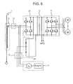
- the present embodiment is an embodiment in which one converter is connected to one wire on the low pressure side of the main transformer 11, and a power conversion circuit 24 made of diodes is applied in place of the power conversion circuit 23 for one phase of the embodiment shown in FIG. 5 .
- the other configuration of the drive system and the changeover flow of the power are the same as in the first and second embodiments.
Abstract
Description
- The present invention relates to a drive device of an electric motor, and particularly, to a drive device for railway vehicle that obtains power from a plurality of different power sources.
- A railway includes two types of routes: a route provided with a facility that supplies power to a train from the ground through a trolley wire or a third rail (hereinafter, called "electrified route"); and a route without a power supply facility from the ground, in which power generation means included in the train obtains power (or motive power is obtained from a motive power source) (hereinafter, called "non-electrified route"). In the electrified route, regenerative electric power generated during braking of the train can be consumed by another train. Therefore, the energy efficiency is generally higher in the electrified system, and there is a tendency to preferentially electrify routes with a greater number of trains. Recently, a plan for electrifying non-electrified routes is developed on the background of the rise in the energy price.
- Meanwhile, a train that can travel regardless of whether the route is electrified or non-electrified is desirable to efficiently operate the train. An example of widely used means for realizing such a train includes a system of pulling a train formation including vehicles without electric power sources/motive power sources by an electric locomotive in the electrified route and pulling the train formation by a diesel locomotive including an internal combustion engine as a motive power source in the non-electrified route.
- Regardless of whether the locomotive is an electric locomotive or a diesel locomotive, a locomotive is provided with a large number of apparatuses, and the weight of the locomotive is usually several times higher than the weight of a passenger car constituting the train. For example, compared to a power-dispersed train, such as a Shinkansen train travelling in Japan, in which a drive device and other functions necessary for the train are dispersed, the locomotive has a problem that the track is significantly damaged by a heavy axle or has a problem that there is a limit to speeding up the train because a large-capacity brake device is necessary for a vehicle with concentrated weight.
- On the other hand, a function-dispersed train needs to have the functions optimized for each of the electrified route and the non-electrified route, and there is a problem that the functions cannot be shared.
- To solve the problems,
EP 1 186497 A1FIG. 1 : 11, 12, 21, and 31 inEP 1 186497 A1FIG. 1 : 13, 20, and 32 inEP 1 186497 A1 - However, in
EP 1 186497 A1FIG. 1 : 13, 25, and 32 inEP 1 186497 A1FIG. 1: 1 inEP 1 186497 A1 - An example of means for solving the problems includes a drive system, in which control is performed to convert AC voltages from the power sources (overhead contact line, power generator driven by engine, and the like) to DC voltages according to the AC voltages of the power sources to thereby standardize converters for a plurality of power sources. However, in the drive system, physical circuits as well as the control of the converters need to be switched when the train enters the non-electrified route from the electrified route and when the train enters the electrified route from the non-electrified route. There is a problem that the changeover is more complicated than in
EP 1 186497 A1 - In this way, there is a problem that realization of stable drive while ensuring the safety of the device is difficult, when the physical circuits and the control of the converters are switched. If an attempt is made to ensure the safety of the device or to stabilize the drive, there is a problem that a long time is required for the changeover. If a long time is required for the changeover, the time that the formation cannot be accelerated is long. Therefore, an operation schedule needs to be formed by considering the time that the acceleration is not possible, and there is a problem that the degree of freedom in the operation is reduced. The time that the supply of power to auxiliary apparatuses in the vehicle, such as an air conditioner and a lighting device, is cut off is long, and there is a problem that the service for the passengers is degraded.
- An object of the present invention is to realize stable drive while ensuring safety of a device when power sources are changed over in a drive system including converters standardized for a plurality of power sources. Another object of the present invention is to quickly perform the changeover.
- Provided as means for addressing the problems is a drive system including: a first power conversion device that converts AC power to DC power; and a second power conversion device that drives an electric motor by using the DC power converted by the first power conversion device as a power supply, wherein the first power conversion device is connected, through a first contactor, to a first AC power supply that supplies a single-phase alternating current and connected, through a second contactor, to a second AC power supply that supplies a three-phase alternating current, and the first power conversion device performs a power conversion operation according to the AC power supplies connected to the first and second contactors, the drive system further including, when an AC side of the first power conversion device is switched from the first AC power supply to the second AC power supply: a first step of terminating a switching operation of the first power conversion device to open the first contactor; a second step of closing the second contactor to start a switching operation of converting a single-phase alternating current to a direct current by the first power conversion device; and a third step of permitting torque output from the electric motor.
- Provided is a drive system including, when the AC side of the first power conversion device is switched from the second AC power supply to the first AC power supply: a first step of terminating the switching operation of the first power conversion device to open the second contactor; a second step of closing the first contactor to start a switching operation of converting a three-phase alternating current to a direct current by the first power conversion device; and a third step of permitting torque output from the electric motor.
- The present invention can realize stable drive while ensuring safety of a device when power sources are changed over in a drive system including converters standardized for a plurality of power sources. The present invention can also quickly perform the changeover.
-
-
FIG. 1 is a drive system diagram showing an embodiment of the present invention; -
FIG. 2 is a diagram showing a configuration example when a drive system of the present invention is mounted on a train; -
FIG. 3 is a diagram showing a changeover flow when the train enters a non-electrified route from an electrified route; -
FIG. 4 is a diagram showing a changeover flow when the train enters an electrified route from a non-electrified route; -
FIG. 5 is another drive system diagram showing an embodiment of the present invention; and -
FIG. 6 is another drive system diagram showing an embodiment of the present invention. - Embodiments of the present invention will now be described with reference to the drawings. An example of a drive system for railway vehicle of the present invention and an example of application to a railway vehicle formation will be described with reference to
FIGS. 1 to 6 . - As shown in
FIG. 1 , a drive system of the present embodiment includes: apower collector 1 that receives single-phase AC power from an overhead contact line (not shown) connected to a substation that is a single-phase AC power supply; and amain transformer 11 that steps down an overhead contact line voltage. Two wires are arranged on the low pressure side of themain transformer 11, and a single-phase alternating current is supplied to each wire. The drive system is a drive system for railway vehicle including apower conversion circuit 21 for power supply and apower conversion circuit 22 for power supply, each including two phases of switch circuits and converting AC power to DC power, the switching circuits formed by connecting two connectors in series, the connectors including semiconductor elements (for example, IGBT) with self-extinction capability and diodes connected in antiparallel. The drive system further includes: acontactor 12 connected between themain transformer 11 and thepower conversion circuits smoothing capacitor 3 that is connected to the DC side of thepower conversion circuits conversion circuit 4 for driving electric motor that includes a combination of semiconductor elements and that drives a mainelectric motor 5 by using the voltage at both ends of thesmoothing capacitor 3 as a voltage source; apower generation unit 6 that includes an engine and a power generator connected to the engine and that supplies a three-phase AC power supply; connection points of themain transformer 11 and thepower conversion circuits power conversion circuits contactor 13 connected to a three-phase AC output of thepower generation unit 6. - In the example of
FIG. 1 , when the train travels under an overhead contact line, that is, in an electrified route, thecontactor 12 is closed, and thecontactor 13 is opened. Themain transformer 11 supplies single-phase AC power to thepower conversion circuits power conversion circuits power conversion circuits conversion circuit 4 for driving electric motor drives the mainelectric motor 5. - On the other hand, when the train travels a route without an overhead contact line, that is, in a non-electrified route, the
contactor 12 is opened, and thecontactor 13 is closed. Two phases of the three-phase alternating current supplied from thepower generation unit 6 are connected to the AC side of thepower conversion circuit 21 for power supply, and the remaining one phase is connected to the semiconductor element constituting onephase 221 of the power conversion circuits for two phases constituting thepower conversion circuit 22 for power supply. The semiconductor elements constituting the onephase 221 of thepower conversion circuit 22 for power supply and the power conversion circuits of the two phases of thepower conversion circuit 21 for power supply are appropriately switched to convert the three-phase alternating current to a direct current, and the three-phase AC output voltage of thepower generation unit 6 is converted to a DC voltage. To prevent unnecessary switching, an off command is provided to the semiconductor elements constituting onephase 222 of thepower conversion circuit 22 for power supply that is not switched. The advantageous effects of the present invention can be attained by performing the control described above when the vehicle is travelling under the overhead contact line (electrified route) and the overhead contact line is in an abnormal state. -
FIG. 2 shows a configuration diagram when the drive system shown inFIG. 1 is mounted on a formation train.FIG. 2 shows an example that four drive systems shown inFIG. 1 are mounted on a plurality of vehicles. In this example, thepower collector 1 and themain transformer 11 are mounted on the first and last vehicles, and front two drive systems receive single-phase alternating currents (from two wires) from themain transformer 11 mounted on the first vehicle. Back two drive systems receive single-phase alternating currents (from two wires) from themain transformer 11 mounted on the last vehicle. A power conversion device 7 inFIG. 2 indicates thepower conversion circuits DC filter capacitor 3, and theconversion circuit 4 for driving electric motor inFIG. 1 . - The
front power collector 1 and theback power collector 1 are connected by apower line 8. Themain transformer 11 of the first vehicle and themain transformer 11 of the last vehicle can receive power from any of thefront power collector 1 and theback power collector 1. Even if there is an abnormality in one of thepower collectors 1, thepower line 8 allows receiving power from theother power collector 1, and the operation can be continued. - In the present embodiment, the
power conversion circuits contactors power conversion circuits - A changeover sequence of the drive system will be described in detail with reference to
FIGS. 3 and4 .FIG. 3 is a changeover flow when the train enters a non-electrified route from an electrified route. In step 101, the facts that the engine is idled, power can be generated, and a notch command from the driver's cab is off are checked, and the process moves to step 102. The drive system may automatically execute the checking process in step 101. Alternatively, the checking status may be displayed in the driver's cab, and the driver may perform the check. - In step 102, a trigger for switching from drive control for electrified route to drive control for non-electrified route is input. The trigger is automatically input by detecting that the train is in a predetermined route for switching from the drive control for electrified route to the drive control for non-electrified route. Alternatively, the driver inputs the trigger. Whether the train is in the predetermined route may be determined from a detection result of the power collector voltage. Alternatively, whether the train is in the predetermined route may be determined from a result of comparison between a travelling position of the train generated by a tacho-generator or GPS and position information of the predetermined route stored in advance. Whether the train is in the predetermined route can also be determined by receiving information of electrified/non-electrified route from a facility on the ground such as a ground member.
- When the changeover trigger is input in step 102, the process moves to
steps step 103, thecontactor 16 and thecontactor 15 are opened to cut off the connection between thepower collector 1 and themain transformer 11. The process moves to step 106. Instep 106, thepower collector 1 is lowered and housed. - In
step 105, the gates of the switching elements of all auxiliary power supplies (APS) in the formation that supply power to the auxiliary apparatuses, such as air conditioners and lighting devices, in the vehicles are turned off to terminate the switching operation. - In
step 104, the gates of the switching elements of allpower conversion circuits contactor 12 is opened to cut off the connection between themain transformer 11 and thepower conversion circuits contactor 13 is open when the train travels on the electrified route. Therefore, allpower conversion circuits - In step 107, the
contactor 13 is closed to connect the power generator and thepower conversion circuits contactor 13 is closed after opening thecontactor 12, and application of a large voltage caused by connection of themain transformer 11 and the power generator can be prevented. The process moves to step 108. - In step 108, the switching operation of all
power conversion circuits power conversion circuits phase 221 of thepower conversion circuit 22 for power supply and the power conversion circuits of the two phases of thepower conversion circuit 21 for power supply to convert the three-phase alternating current to a direction current to thereby convert the three-phase AC output voltage of thepower generation unit 6 to a DC voltage. To prevent unnecessary switching, an off command is provided to the semiconductor elements constituting the onephase 222 not connected to the power generator of thepower conversion circuit 22 for power supply. The process moves to step 109. - In
step 109, the switching operation of all auxiliary power supplies (APS) in the formation is restarted to start supplying power to the auxiliary apparatuses. - In
step 110, if AND conditions that thecontactor 16 and thecontactor 15 are opened instep 103 and that all auxiliary power supplies (APS) in the formation have restarted the switching operation instep 109 are satisfied, the process moves to step 111. Although the restart of the switching operation by all auxiliary power supplies (APS) in the formation is one of the AND conditions ofstep 110 inFIG. 3 , the start of the switching operation by all converters in the formation in step 108 may be one of the AND conditions in place ofstep 109. - In
step 111, on the condition that the AND conditions ofstep 110 are satisfied, the operation of theconversion circuit 4 for driving electric motor is started according to a notch input from the driver's cab, and torque output from the mainelectric motor 5 is permitted. In other words, if the AND conditions are not satisfied instep 110, the torque output from the mainelectric motor 5 is prohibited. - Although all of steps 101 to 111 have been described in
FIG. 3 , the minimum requirements for generating the advantageous effects of the present invention aresteps - The converters and the power generator are connected after turning off the gates of all converters in the formation and cutting off the connection between the converters and the overhead contact line. This can prevent connection of the overhead contact line with the power generator and application of an excessive voltage to the power generator and the like. The torque output from the main electric motor is permitted after all converters in the formation have started the switching operation for non-electrified route. Therefore, the torque output is permitted when the input voltage of the
conversion circuit 4 for driving electric motor is reserved, and stable drive output is possible. As a result, the semiconductor elements constituting the power conversion circuit that generates DC power can be standardized for the power supplies, and stable drive can be realized while ensuring the safety. These advantageous effects of the present invention can be attained. - Inclusion of
steps step 103 andsteps 104, 107 to 109. Therefore, the changeover can be quickly performed even when a disconnection process of the power collector and the main transformer is executed. Inclusion ofstep 105 allows parallel execution ofstep 105 andsteps 104, 107 to 109. Therefore, the changeover can be quickly performed. - A changeover flow when the train enters an electrified route from a non-electrified route will be described with reference to
FIG. 4 . In step 201, the facts that thepower collector 1 is raised, power can be received from the overhead contact line, and a notch command from the driver's cab is off are checked, and the process moves to step 202. The drive system may automatically execute the checking process in step 201. Alternatively, the checking status may be displayed in the driver's cab, and the driver may perform the check. - In
step 202, a trigger for switching from drive control for non-electrified route to drive control for electrified route is input. The trigger is automatically input by detecting that the train is in a predetermined route for switching from the drive control for non-electrified route to the drive control for electrified route. Alternatively, the driver inputs the trigger. Whether the train is in the predetermined route may be determined from a detection result of the power collector voltage. Alternatively, whether the train is in the predetermined route may be determined from a result of comparison between a travelling position of the train generated by a tacho-generator or GPS and position information of the predetermined route stored in advance. Whether the train is in the predetermined route can also be determined by receiving information of electrified/non-electrified route from a facility on the ground such as a ground member. - When the changeover trigger is input in
step 202, the process moves tosteps 203, 204, and 205. In step 203, thecontactor 16 and thecontactor 15 are closed to connect thepower collector 1 and themain transformer 11. - In
step 205, the gates of the switching elements of all auxiliary power supplies (APS) in the formation are turned off to terminate the switching operation. - In step 204, the gates of the switching elements of all
power conversion circuits contactor 13 is opened to cut off the connection between the power generator and thepower conversion circuits contactor 12 is open when the train travels on the non-electrified route. Therefore, allpower conversion circuits steps - In
step 210, if AND conditions that thecontactor 16 and thecontactor 15 are opened in step 203 and that the switching operation of the converters are terminated to open the contactor 13 in step 204 are satisfied, the process moves to step 206. Instep 206, thecontactor 12 is closed to connect themain transformer 11 and thepower conversion circuits contactor 12 is closed after opening thecontactor 13, and application of a large voltage caused by connection of themain transformer 11 and the power generator can be prevented. The process moves to step 207. Thecontactor 12 includes a resistor (not shown) that prevents a rush current, and thecontactor 12 needs to be closed after closing thecontactors FIG. 1 when the overhead contact line and the converter 7 are connected. - In step 207, the switching operation of all
power conversion circuits main transformer 11 supplies single-phase AC power to thepower conversion circuits power conversion circuits power conversion circuits power conversion circuits - In
step 208, the switching operation of all auxiliary power supplies (APS) in the formation is restarted to start supplying power to the auxiliary apparatuses. The process moves to steps 211 and 212. - The engine is idled in
step 209. In this way, the gates of the converters are turned off to cut off the connection between the power generator and the converters in step 204, and then the engine is idled. This can prevent a situation that the converters cannot obtain desired power from the power generator, and stable control is possible. - In
FIG. 4 , the restart of the switching operation by all auxiliary power supplies (APS) in the formation is the condition for movement to steps 211 and 212. However, in place ofstep 208, the start of the switching operation by all converters in the formation in step 207 may be the condition for movement to steps 211 and 212. - In step 211, on the condition that the AND conditions of
step 210 are satisfied, the operation of theconversion circuit 4 for driving electric motor is started according to a notch input from the driver's cab, and torque output from the mainelectric motor 5 is permitted. In other words, if the AND conditions are not satisfied instep 210, the torque output from the mainelectric motor 5 is prohibited. - In step 212, the engine is terminated on the condition that step 208 is satisfied. The engine is activated (idled) before the satisfaction of
step 208 or 207, and the engine is terminated after the satisfaction ofstep 208 or 207. In this way, there is an advantageous effect of a quick shift to the drive system for non-electrified route by the engine when the changeover to the drive system for electrified route is not attained due to an abnormality. - Although all of steps 201 to 212 have been described in
FIG. 4 , the minimum requirements for generating the advantageous effects of the present invention aresteps - The converters and the overhead contact line are connected after turning off the gates of all converters in the formation and cutting off the connection between the converters and the power generator. This can prevent connection of the overhead contact line with the power generator and application of an excessive voltage to the power generator and the like. The torque output from the main electric motor is permitted after all converters in the formation have started the switching operation for electrified route. Therefore, the torque output is permitted when the input voltage of the
conversion circuit 4 for driving electric motor is reserved, and stable drive control is possible. As a result, the semiconductor elements constituting the power conversion circuit that generates DC power can be standardized for the power supplies, and stable drive can be realized while ensuring the safety. These advantageous effects of the present invention can be attained. - Inclusion of
steps 203 and 210 in addition to the minimum requirements allows parallel execution of step 203 andsteps 204, 205. Therefore, the changeover can be quickly performed even when a connection process of the power collector and the main transformer is executed. Inclusion ofstep 205 allows parallel execution ofstep 205 andsteps 204, 206 to 208. Therefore, the changeover can be quickly performed. InFIG. 4 , step 210 of taking the AND conditions of steps 203 and 204 is arranged beforestep 206. However, if a measure for preventing a rush current to the DC filter capacitor is taken, the condition for movement to step 206 may be the completion of step 204, and the conditions for movement to steps 211 and 212 may be AND conditions of the completions ofsteps 203 and 208. - Another embodiment will be described with reference to
FIG. 5 . The present embodiment illustrates an example when one converter is connected to one wire on the low pressure side of themain transformer 11. In the present embodiment, thepower conversion circuit 21 for power supply is connected to one wire on the low pressure side of themain transformer 11, and acontactor 14 is connected between the one wire on the low pressure side and thepower conversion circuit 21 for power supply. More specifically, thecontactor 14 for one phase (two phase) type is connected, in place of thecontactor 12 inFIG. 1 . Apower conversion circuit 23 for power supply for one phase of the power conversion circuit is further included, in place of thepower conversion circuit 22 for power supply inFIG. 1 . More specifically, two phases of the three-phase alternating current supplied from thepower generation unit 6 is connected to the AC side of thepower conversion circuit 21 for power supply, and the remaining one phase is connected to the AC side of thepower conversion circuit 23 for power supply. The other configuration of the drive system and the changeover flow are the same as in the first embodiment. - In the example of
FIG. 5 , thecontactor 14 is closed, and thecontactor 13 is opened under the overhead contact line, that is, in the electrified route. The overhead contact line serves as a power supply, and the semiconductor elements constituting thepower conversion circuit 21 for power supply are appropriately switched to convert the single-phase alternating current to a direct current to obtain a DC voltage. Theconversion circuit 4 for driving electric motor drives the mainelectric motor 5. In this case, an off command is provided to the semiconductor elements constituting thepower conversion circuit 23 for power supply to prevent unnecessary switching. - On the other hand, the
contactor 14 is opened, and thecontactor 13 is closed in a route without the overhead contact line, that is, in the non-electrified route. The semiconductor elements constituting thepower conversion circuit 21 for power supply and thepower conversion circuit 23 for power supply for one phase are appropriately switched to convert the three-phase alternating current to a direct current, and the three-phase AC output of thepower generation unit 6 is converted to a direct current. - Another embodiment will be described with reference to
FIG. 6 . The present embodiment is an embodiment in which one converter is connected to one wire on the low pressure side of themain transformer 11, and apower conversion circuit 24 made of diodes is applied in place of thepower conversion circuit 23 for one phase of the embodiment shown inFIG. 5 . The other configuration of the drive system and the changeover flow of the power are the same as in the first and second embodiments. - In the example of the configuration diagram of
FIG. 2 including the drive system of the embodiments mounted on the train, four drive systems are dispersed and mounted on four vehicles. However, the number of drive systems mounted on the train is not particularly limited. Passenger cars may be appropriately added between the vehicles provided with the drive systems according to the required traffic volume.
Claims (13)
- A drive system comprising:a first power conversion device that converts AC power to DC power; anda second power conversion device that drives an electric motor by using the DC power converted by the first power conversion device as a power supply, whereinthe first power conversion device is connected, through a first contactor, to a first AC power supply that supplies a single-phase alternating current and connected, through a second contactor, to a second AC power supply that supplies a three-phase alternating current, andthe first power conversion device performs a power conversion operation according to the AC power supplies connected to the first and second contactors,the drive system being configured, when an AC side of the first power conversion device is switched from the first AC power supply to the second AC power supply, to perform:a first step of terminating a switching operation of the first power conversion device to open the first contactor;a second step of closing the second contactor to start a switching operation of converting a three-phase alternating current to a direct current by the first power conversion device; anda third step of permitting torque output from the electric motor.
- The drive system according to claim 1, further comprising:a power collector that collects AC power from the first AC power supply; anda transformer connected to the power collector through a third contactor on a primary wire side and connected to the first power conversion device through the first contactor on a secondary wire side, the transformer stepping down the AC power from the first AC power supply to supply the AC power to the first power conversion device, whereinthe drive system is configured such that, when the AC side of the first power conversion device is switched from the first AC power supply to the second AC power supply,an opening operation of the third contactor is carried out in parallel with the first and second steps, andthe third step is carried out on a condition that the second step and the opening of the third contactor are completed.
- The drive system according to claim 2, wherein
the power collector is moved to a storage position after opening the third contactor. - The drive system according to any one of claims 1 to 3, further comprising
an auxiliary power supply that supplies power to an auxiliary apparatus in a vehicle by using the DC power output from the first power conversion device as a power supply, wherein
the drive system is configured such that, when the AC side of the first power conversion device is switched from the first AC power supply to the second AC power supply,
switching termination of the auxiliary power supply is carried out in parallel with the first and second steps. - The drive system according to any one of claims 1 to 4, which is further configured such that when the AC side of the first power conversion device is switched from the second AC power supply to the first AC power supply:a first step of terminating the switching operation of the first power conversion device to open the second contactor;a second step of closing the first contactor to start a switching operation of converting a single-phase alternating current to a direct current by the first power conversion device; anda third step of permitting torque output from the electric motor.
- The drive system according to claim 5, further comprising:a power collector that collects AC power from the first AC power supply; anda transformer connected to the power collector through the third contactor on the primary wire side and connected to the first power conversion device through the first contactor on the secondary wire side, the transformer stepping down the AC power from the first AC power supply to supply the AC power to the first power conversion device, whereinthe drive system is configured such that, when the AC side of the first power conversion device is switched from the second AC power supply to the first AC power supply,the first step is carried out in parallel with an operation of closing the third contactor, the second step is carried out on a condition that the first step and the operation of closing the third contactor are completed, andthe third step is carried out on a condition that the second step is completed.
- The drive system according to claim 5 or 6, further comprising
an auxiliary power supply that uses, as a power supply, the DC power output from the first power conversion device to supply power to an auxiliary apparatus in a vehicle, wherein
the drive system is configured such that, when the AC side of the first power conversion device is switched from the second AC power supply to the first AC power supply,
switching termination of the auxiliary power supply is carried out in parallel with the first and second steps. - The drive system according to any one of claims 1 to 7 further comprising an engine.
- The drive system according claim 8, further comprising a power generator operated by the engine, the power generator supplying the three-phase alternating current of the second AC power supply.
- The drive system according to claim 8 or 9 as dependent on claim 5, which is configured such that
when the AC side of the first power conversion device is switched from the second AC power supply to the first AC power supply, the engine is terminated after the second step is carried out. - The drive system according to claim 10, which is configured such that
when the AC side of the first power conversion device is switched from the second AC power supply to the first AC power supply, the engine is switched to an idling state after the first step is carried out - The drive system according to claim 8 or 9 as dependent on any of claims 5 to 7, which is configured such that
when the AC side of the first power conversion device is switched from the second AC power supply to the first AC power supply, the engine is switched to an idling state after the first step is carried out. - A railway vehicle provided with the drive system according to any of claims 1 to 12.
Applications Claiming Priority (1)
| Application Number | Priority Date | Filing Date | Title |
|---|---|---|---|
| JP2012166491A JP5891989B2 (en) | 2012-07-27 | 2012-07-27 | Drive system and railway vehicle equipped with the same |
Publications (3)
| Publication Number | Publication Date |
|---|---|
| EP2689983A1 true EP2689983A1 (en) | 2014-01-29 |
| EP2689983B1 EP2689983B1 (en) | 2016-01-06 |
| EP2689983B2 EP2689983B2 (en) | 2023-07-26 |
Family
ID=48874816
Family Applications (1)
| Application Number | Title | Priority Date | Filing Date |
|---|---|---|---|
| EP13177319.4A Active EP2689983B2 (en) | 2012-07-27 | 2013-07-19 | Drive system and railway vehicle provided with the drive system |
Country Status (2)
| Country | Link |
|---|---|
| EP (1) | EP2689983B2 (en) |
| JP (1) | JP5891989B2 (en) |
Cited By (7)
| Publication number | Priority date | Publication date | Assignee | Title |
|---|---|---|---|---|
| WO2017093273A1 (en) * | 2015-11-30 | 2017-06-08 | Abb Schweiz Ag | Power converter |
| EP3501934A1 (en) * | 2017-12-19 | 2019-06-26 | ABB Schweiz AG | Cooling system and method for a dual-powered railroad vehicle |
| WO2019153720A1 (en) * | 2018-02-08 | 2019-08-15 | 中车株洲电力机车有限公司 | Hybrid railway vehicle |
| EP3878680A2 (en) | 2020-03-13 | 2021-09-15 | Hitachi Rail Limited | Drive system for a railway vehicle |
| GB202114080D0 (en) | 2021-10-01 | 2021-11-17 | Hitachi Rail Ltd | Drive system for a railway vehicle |
| EP4249344A1 (en) | 2022-03-23 | 2023-09-27 | Hitachi Rail Limited | Train operable in hybrid and battery-only modes |
| EP4249346A1 (en) | 2022-03-23 | 2023-09-27 | Hitachi Rail Limited | System, train, remote control centre, and method |
Families Citing this family (2)
| Publication number | Priority date | Publication date | Assignee | Title |
|---|---|---|---|---|
| JP6393643B2 (en) * | 2015-03-26 | 2018-09-19 | 株式会社日立製作所 | Vehicle drive system |
| JP6823313B2 (en) * | 2016-10-25 | 2021-02-03 | 株式会社日立製作所 | AC overhead wire type storage battery car |
Citations (2)
| Publication number | Priority date | Publication date | Assignee | Title |
|---|---|---|---|---|
| EP1186497A1 (en) | 2000-09-12 | 2002-03-13 | ALSTOM LHB GmbH | Railway vehicle with power supply system |
| EP2444272A1 (en) * | 2009-06-15 | 2012-04-25 | Hitachi, Ltd. | Driving system for railroad vehicle |
Family Cites Families (13)
| Publication number | Priority date | Publication date | Assignee | Title |
|---|---|---|---|---|
| DE4335849C1 (en) | 1993-10-20 | 1995-06-01 | Voith Gmbh J M | Drive device for a means of transport |
| DE9415770U1 (en) | 1994-09-30 | 1994-12-15 | Abb Henschell Ag | Rail-bound diesel traction vehicle |
| JPH09168204A (en) † | 1995-12-15 | 1997-06-24 | Toshiba Corp | Control device of electric car |
| JP2001037005A (en) * | 1999-07-23 | 2001-02-09 | Toshiba Corp | Electric rolling stock driving system |
| JP2004312953A (en) * | 2003-04-10 | 2004-11-04 | Hitachi Ltd | Hybrid transportation vehicle |
| WO2008047439A1 (en) | 2006-10-19 | 2008-04-24 | Mitsubishi Electric Corporation | Power converter |
| GB0625121D0 (en) | 2006-12-18 | 2007-01-24 | Gendrive Ltd | Electrical energy converter |
| DE102009008549A1 (en) † | 2009-02-12 | 2010-08-19 | Bombardier Transportation Gmbh | Arrangement for operating loads in a rail vehicle with electrical energy, optionally from a power supply network or from a motor-generator combination |
| JP5248428B2 (en) | 2009-07-09 | 2013-07-31 | タカノ株式会社 | Parts mounting structure |
| RU2422299C1 (en) † | 2009-12-07 | 2011-06-27 | Ооо "Гамем" | Power supply system of electric train with asynchronous traction drive |
| JP5801999B2 (en) * | 2010-08-24 | 2015-10-28 | 株式会社日立製作所 | Train trains equipped with railway on-board electrical equipment |
| CN103338967B (en) | 2011-01-31 | 2015-11-25 | 株式会社日立制作所 | Drive system, railway vehicle drive system and carried railway vehicle, the marshaling of this system |
| JP5770484B2 (en) | 2011-02-16 | 2015-08-26 | 株式会社小森コーポレーション | Method and apparatus for detecting sheet-like corner breakage of sheet-fed printing press |
-
2012
- 2012-07-27 JP JP2012166491A patent/JP5891989B2/en active Active
-
2013
- 2013-07-19 EP EP13177319.4A patent/EP2689983B2/en active Active
Patent Citations (2)
| Publication number | Priority date | Publication date | Assignee | Title |
|---|---|---|---|---|
| EP1186497A1 (en) | 2000-09-12 | 2002-03-13 | ALSTOM LHB GmbH | Railway vehicle with power supply system |
| EP2444272A1 (en) * | 2009-06-15 | 2012-04-25 | Hitachi, Ltd. | Driving system for railroad vehicle |
Cited By (10)
| Publication number | Priority date | Publication date | Assignee | Title |
|---|---|---|---|---|
| WO2017093273A1 (en) * | 2015-11-30 | 2017-06-08 | Abb Schweiz Ag | Power converter |
| US11056980B2 (en) | 2015-11-30 | 2021-07-06 | Abb Schweiz Ag | Power converter |
| EP3501934A1 (en) * | 2017-12-19 | 2019-06-26 | ABB Schweiz AG | Cooling system and method for a dual-powered railroad vehicle |
| US11267490B2 (en) | 2017-12-19 | 2022-03-08 | Hitachi Energy Switzerland Ag | Cooling system and method for a dual-powered railroad vehicle |
| WO2019153720A1 (en) * | 2018-02-08 | 2019-08-15 | 中车株洲电力机车有限公司 | Hybrid railway vehicle |
| EP3878680A2 (en) | 2020-03-13 | 2021-09-15 | Hitachi Rail Limited | Drive system for a railway vehicle |
| GB202114080D0 (en) | 2021-10-01 | 2021-11-17 | Hitachi Rail Ltd | Drive system for a railway vehicle |
| GB2611341A (en) | 2021-10-01 | 2023-04-05 | Hitachi Rail Ltd | Drive system for a railway vehicle |
| EP4249344A1 (en) | 2022-03-23 | 2023-09-27 | Hitachi Rail Limited | Train operable in hybrid and battery-only modes |
| EP4249346A1 (en) | 2022-03-23 | 2023-09-27 | Hitachi Rail Limited | System, train, remote control centre, and method |
Also Published As
| Publication number | Publication date |
|---|---|
| JP5891989B2 (en) | 2016-03-23 |
| JP2014027790A (en) | 2014-02-06 |
| EP2689983B1 (en) | 2016-01-06 |
| EP2689983B2 (en) | 2023-07-26 |
Similar Documents
| Publication | Publication Date | Title |
|---|---|---|
| EP2689983B1 (en) | Drive system and railway vehicle provided with the drive system | |
| US9090165B2 (en) | Driving system, driving system for railroad-vehicle, and railroad-vehicle and multi-car train mounted with same | |
| US9227516B2 (en) | Electric vehicle propulsion control device and railway vehicle system | |
| EP2241472B1 (en) | Power storage control apparatus and method of electric vehicle | |
| JP4747204B2 (en) | Railway system with power supply equipment on the railway line between stations | |
| EP2570292A1 (en) | Alternating-current electric vehicle | |
| EP2738034B1 (en) | Electric vehicle propulsion control device | |
| US20130181679A1 (en) | Passenger bus with on-board charger | |
| JP2010130829A (en) | Drive system foe electric railway vehicle | |
| JP2015053837A (en) | Electric power supply system and method for railway vehicle during power outage | |
| JP2012178898A (en) | Drive system for railway vehicle, railway vehicle, and train organization including the railway vehicle | |
| US20200076225A1 (en) | Passenger bus with on-board charger | |
| JP2005051891A (en) | Feeding apparatus, composition of train, and tracked rolling stock |
Legal Events
| Date | Code | Title | Description |
|---|---|---|---|
| PUAI | Public reference made under article 153(3) epc to a published international application that has entered the european phase |
Free format text: ORIGINAL CODE: 0009012 |
|
| 17P | Request for examination filed |
Effective date: 20130805 |
|
| AK | Designated contracting states |
Kind code of ref document: A1 Designated state(s): AL AT BE BG CH CY CZ DE DK EE ES FI FR GB GR HR HU IE IS IT LI LT LU LV MC MK MT NL NO PL PT RO RS SE SI SK SM TR |
|
| AX | Request for extension of the european patent |
Extension state: BA ME |
|
| 17Q | First examination report despatched |
Effective date: 20140425 |
|
| GRAP | Despatch of communication of intention to grant a patent |
Free format text: ORIGINAL CODE: EPIDOSNIGR1 |
|
| INTG | Intention to grant announced |
Effective date: 20150930 |
|
| GRAS | Grant fee paid |
Free format text: ORIGINAL CODE: EPIDOSNIGR3 |
|
| GRAA | (expected) grant |
Free format text: ORIGINAL CODE: 0009210 |
|
| STAA | Information on the status of an ep patent application or granted ep patent |
Free format text: STATUS: THE PATENT HAS BEEN GRANTED |
|
| RBV | Designated contracting states (corrected) |
Designated state(s): DE GB |
|
| AK | Designated contracting states |
Kind code of ref document: B1 Designated state(s): DE GB |
|
| REG | Reference to a national code |
Ref country code: GB Ref legal event code: FG4D |
|
| REG | Reference to a national code |
Ref country code: DE Ref legal event code: R096 Ref document number: 602013004443 Country of ref document: DE |
|
| REG | Reference to a national code |
Ref country code: DE Ref legal event code: R026 Ref document number: 602013004443 Country of ref document: DE |
|
| PLBI | Opposition filed |
Free format text: ORIGINAL CODE: 0009260 |
|
| PLAX | Notice of opposition and request to file observation + time limit sent |
Free format text: ORIGINAL CODE: EPIDOSNOBS2 |
|
| 26 | Opposition filed |
Opponent name: SIEMENS AKTIENGESELLSCHAFT Effective date: 20161006 Opponent name: BOMBARDIER TRANSPORTATION GMBH Effective date: 20161006 |
|
| PLAF | Information modified related to communication of a notice of opposition and request to file observations + time limit |
Free format text: ORIGINAL CODE: EPIDOSCOBS2 |
|
| PLBB | Reply of patent proprietor to notice(s) of opposition received |
Free format text: ORIGINAL CODE: EPIDOSNOBS3 |
|
| PLAB | Opposition data, opponent's data or that of the opponent's representative modified |
Free format text: ORIGINAL CODE: 0009299OPPO |
|
| R26 | Opposition filed (corrected) |
Opponent name: SIEMENS AKTIENGESELLSCHAFT Effective date: 20161006 |
|
| PLCK | Communication despatched that opposition was rejected |
Free format text: ORIGINAL CODE: EPIDOSNREJ1 |
|
| STAA | Information on the status of an ep patent application or granted ep patent |
Free format text: STATUS: THE PATENT HAS BEEN GRANTED |
|
| APBM | Appeal reference recorded |
Free format text: ORIGINAL CODE: EPIDOSNREFNO |
|
| APBP | Date of receipt of notice of appeal recorded |
Free format text: ORIGINAL CODE: EPIDOSNNOA2O |
|
| APAH | Appeal reference modified |
Free format text: ORIGINAL CODE: EPIDOSCREFNO |
|
| APBM | Appeal reference recorded |
Free format text: ORIGINAL CODE: EPIDOSNREFNO |
|
| APBP | Date of receipt of notice of appeal recorded |
Free format text: ORIGINAL CODE: EPIDOSNNOA2O |
|
| APBQ | Date of receipt of statement of grounds of appeal recorded |
Free format text: ORIGINAL CODE: EPIDOSNNOA3O |
|
| APBQ | Date of receipt of statement of grounds of appeal recorded |
Free format text: ORIGINAL CODE: EPIDOSNNOA3O |
|
| REG | Reference to a national code |
Ref country code: DE Ref legal event code: R082 Ref document number: 602013004443 Country of ref document: DE Representative=s name: MEWBURN ELLIS LLP, DE |
|
| APBU | Appeal procedure closed |
Free format text: ORIGINAL CODE: EPIDOSNNOA9O |
|
| PLAY | Examination report in opposition despatched + time limit |
Free format text: ORIGINAL CODE: EPIDOSNORE2 |
|
| PLBC | Reply to examination report in opposition received |
Free format text: ORIGINAL CODE: EPIDOSNORE3 |
|
| PLAY | Examination report in opposition despatched + time limit |
Free format text: ORIGINAL CODE: EPIDOSNORE2 |
|
| PLAT | Information related to reply to examination report in opposition deleted |
Free format text: ORIGINAL CODE: EPIDOSDORE3 |
|
| PLBC | Reply to examination report in opposition received |
Free format text: ORIGINAL CODE: EPIDOSNORE3 |
|
| PLBC | Reply to examination report in opposition received |
Free format text: ORIGINAL CODE: EPIDOSNORE3 |
|
| PLAB | Opposition data, opponent's data or that of the opponent's representative modified |
Free format text: ORIGINAL CODE: 0009299OPPO |
|
| R26 | Opposition filed (corrected) |
Opponent name: SIEMENS AKTIENGESELLSCHAFT Effective date: 20161006 |
|
| PUAH | Patent maintained in amended form |
Free format text: ORIGINAL CODE: 0009272 |
|
| STAA | Information on the status of an ep patent application or granted ep patent |
Free format text: STATUS: PATENT MAINTAINED AS AMENDED |
|
| 27A | Patent maintained in amended form |
Effective date: 20230726 |
|
| AK | Designated contracting states |
Kind code of ref document: B2 Designated state(s): DE GB |
|
| REG | Reference to a national code |
Ref country code: DE Ref legal event code: R102 Ref document number: 602013004443 Country of ref document: DE |
|
| PGFP | Annual fee paid to national office [announced via postgrant information from national office to epo] |
Ref country code: GB Payment date: 20230601 Year of fee payment: 11 |
|
| PGFP | Annual fee paid to national office [announced via postgrant information from national office to epo] |
Ref country code: DE Payment date: 20230531 Year of fee payment: 11 |