EP2689887A1 - Tension device for prestressing an assembly by means of a threaded rod, and method for assembling the tension device - Google Patents
Tension device for prestressing an assembly by means of a threaded rod, and method for assembling the tension device Download PDFInfo
- Publication number
- EP2689887A1 EP2689887A1 EP13177281.6A EP13177281A EP2689887A1 EP 2689887 A1 EP2689887 A1 EP 2689887A1 EP 13177281 A EP13177281 A EP 13177281A EP 2689887 A1 EP2689887 A1 EP 2689887A1
- Authority
- EP
- European Patent Office
- Prior art keywords
- tie
- parts
- skirt
- tension device
- threaded rod
- Prior art date
- Legal status (The legal status is an assumption and is not a legal conclusion. Google has not performed a legal analysis and makes no representation as to the accuracy of the status listed.)
- Granted
Links
Images







Classifications
-
- B—PERFORMING OPERATIONS; TRANSPORTING
- B23—MACHINE TOOLS; METAL-WORKING NOT OTHERWISE PROVIDED FOR
- B23P—METAL-WORKING NOT OTHERWISE PROVIDED FOR; COMBINED OPERATIONS; UNIVERSAL MACHINE TOOLS
- B23P19/00—Machines for simply fitting together or separating metal parts or objects, or metal and non-metal parts, whether or not involving some deformation; Tools or devices therefor so far as not provided for in other classes
- B23P19/04—Machines for simply fitting together or separating metal parts or objects, or metal and non-metal parts, whether or not involving some deformation; Tools or devices therefor so far as not provided for in other classes for assembling or disassembling parts
- B23P19/06—Screw or nut setting or loosening machines
- B23P19/067—Bolt tensioners
-
- B—PERFORMING OPERATIONS; TRANSPORTING
- B25—HAND TOOLS; PORTABLE POWER-DRIVEN TOOLS; MANIPULATORS
- B25B—TOOLS OR BENCH DEVICES NOT OTHERWISE PROVIDED FOR, FOR FASTENING, CONNECTING, DISENGAGING, OR HOLDING
- B25B29/00—Accessories
- B25B29/02—Bolt tensioners
-
- F—MECHANICAL ENGINEERING; LIGHTING; HEATING; WEAPONS; BLASTING
- F16—ENGINEERING ELEMENTS AND UNITS; GENERAL MEASURES FOR PRODUCING AND MAINTAINING EFFECTIVE FUNCTIONING OF MACHINES OR INSTALLATIONS; THERMAL INSULATION IN GENERAL
- F16B—DEVICES FOR FASTENING OR SECURING CONSTRUCTIONAL ELEMENTS OR MACHINE PARTS TOGETHER, e.g. NAILS, BOLTS, CIRCLIPS, CLAMPS, CLIPS OR WEDGES; JOINTS OR JOINTING
- F16B37/00—Nuts or like thread-engaging members
- F16B37/08—Quickly-detachable or mountable nuts, e.g. consisting of two or more parts; Nuts movable along the bolt after tilting the nut
- F16B37/0871—Quickly-detachable or mountable nuts, e.g. consisting of two or more parts; Nuts movable along the bolt after tilting the nut engaging the bolt laterally, i.e. without the need to engage the end of the bolt
Definitions
- the present invention relates to the field of devices for tensioning a rod before it is locked in position, for example by means of a nut, the invention relating in particular to devices for prestressing the threaded rods used for fixing mechanical parts to one another in the nuclear sector, the building sector, or alternatively the wind energy sector.
- Tension devices generally comprise an actuator able to exert an axial traction force on one end of a threaded rod by way of a tie.
- the actuator bears on a surface of a structure to be clamped via a tubular skirt surrounding one end of the threaded rod, opposite the end subjected to the axial force of the actuator.
- the actuator comprises a cylinder and a piston sliding in the cylinder and forming with the cylinder an annular chamber supplied with fluid under pressure.
- Such a tension device is assembled axially and generally has a large axial space requirement, such that it is not possible to use such a tension device in the event of a small space requirement between the threaded rod to be prestressed, the mechanical parts to be assembled and the outside environment.
- the present invention aims to provide a device for tensioning a threaded rod which can be mounted on the threaded rod in the case of a very small space requirement, for example of about 32 mm for a threaded rod having a diameter of 76 mm, while maintaining a large residual prestress load, of the order of 2000 kN.
- the subject of the invention is a device for tensioning a threaded rod comprising an actuator able to exert an axial tensile force on the threaded rod with respect to a structure to be clamped, the said tension device comprising a cylinder, a piston and a tubular skirt in contact with the cylinder and a surface of the said structure to be tensioned, and a tie for transmitting the axial tensile force of the actuator towards an end of the threaded rod.
- the tie and the tubular skirt each comprise at least two semicylindrical parts each having two substantially planar axial surfaces, the two axial surfaces of one semicylindrical part being joined radially respectively with one of the two axial surfaces of the other semicylindrical part, so as to form a part of revolution.
- the tie and the tubular skirt are mounted radially around the threaded rod to be tensioned, thus allowing the assembly of the tension device even in the case of a very small space requirement.
- the tubular skirt comprises means for centring and means for fixing the two semicylindrical skirt parts.
- the means for centring the two skirt parts comprise centring screws screwed into each of the planar axial surfaces of one of the skirt parts and intended to come into planar contact with the planar axial surfaces of the other skirt part.
- the means for fixing the two skirt parts comprise, for example, means made of magnetized material fixed on each of the planar axial surfaces of one of the skirt parts and intended to come into planar contact with the planar axial surfaces of the other skirt part.
- the means made of magnetized material may comprise magnetized washers intended to be housed in a counterbore made in each of the planar axial surfaces of one of the skirt parts and fixed on the said skirt part using fixing means, such as, for example, fixing screws.
- the tie comprises means for centring and means for fixing the two semicylindrical tie parts.
- the means for centring two tie parts comprise pins arranged in holes of corresponding shape made in each of the tie parts perpendicularly to the junction surfaces and centring screws screwed into each of the planar axial surfaces of one of the tie parts and intended to come into planar contact with the planar axial surfaces of the other tie part.
- the means for fixing the two tie parts may comprise a fixing ring surrounding the tie and intended to be clipped onto the tie using clipping means.
- the fixing ring is, for example, maintained in position around the tie by cylindrical pins intended to be housed in a counterbore made in each of the junction surfaces of the two tie parts.
- the invention relates to a method for assembling a tension device as described above, in which the cylinder and the piston are mounted axially on the threaded rod to be prestressed, the two semicylindrical tie parts are assembled radially around the threaded rod and the two semicylindrical parts of the skirt are assembled radially around the threaded rod.
- the radial assembly of the tie and of the tubular skirt around the threaded rod makes it possible to significantly reduce the axial dimension along the axis Y-Y of the tension device.
- the fixing ring is clipped onto the tie.
- the assembly formed by the cylinder and the piston, the two semicylindrical tie parts and the fixing ring can be slid axially by screwing the tie towards the surface of the structure to be clamped and the actuator comes into axial contact against the tubular skirt.
- the tension device of axial axis Y-Y, referenced 1 in its entirety, is intended to axially prestress a threaded rod 2 represented in Figures 10 to 16 .
- the threaded rod 2 is then blocked in position by a nut 3 bearing on a surface 4a of a structure 4 to be clamped, generally comprising at least two mechanical parts to be assembled, and represented in the form of a plate in Figures 10 to 16 .
- the tension device 1 comprises an actuator 5, a tie 6 and a tubular skirt 7.
- the actuator 5 is able to exert an axial traction force on an end 2a of the threaded rod 2 via the tie 6.
- the actuator 5 bears on the surface 4a of the structure 4 to be clamped via the tubular skirt 7 surrounding an end 2b of the threaded rod 2, opposite the end 2a subjected to the axial force of the actuator 5.
- the actuator 5 comprises a cylinder 8 and a piston 9 sliding in the cylinder 8 and forming with the cylinder 8 an annular chamber (not shown) supplied with fluid under pressure.
- the cylinder 8 has the general shape of an annular cup comprising an axial portion 8a having a bore 8b and a base 8c in the form of a radial portion extending inwardly from an end of the axial portion 8a and having a bore 8d.
- the radial portion 8c forms a radial shoulder 8c for the piston 9.
- the base 8c comprises a radial bearing surface 8f in contact with an end 7a of the tubular skirt 7 opposite the end 7b in contact with the surface 4a of the structure 4 to be tensioned.
- the base 8c of the cylinder 8 comprises an axial shoulder 8g extending towards the structure 4 to be tensioned and surrounding the end 7a of the tubular skirt 7 in order to centre the cylinder 8 on the tubular skirt 7 and to maintain the tubular skirt 7 radially with respect to the cylinder 8.
- the piston 9 has an annular general shape comprising an axial tubular portion 9a and an annular collar 9b extending radially outwards from an end of the axial tubular portion 9a.
- the axial tubular portion 9a has a bore 9c of substantially frustoconical shape and an outer surface 9d of substantially cylindrical shape in contact with the bore 8d of the base 8c of the cylinder 8.
- the annular collar 9b comprises an outer axial surface 9e in contact with the bore 8b of the axial portion 8a of the cylinder 8.
- the annular chamber (not shown) is formed axially between the annular collar 9b of the piston 9 and the radial base 8c of the cylinder 8, and radially between the axial portion 8a of the cylinder 8 and the tubular portion 9a of the piston 9.
- the radial base 8c of the cylinder 8 comprises an annular groove 8h formed on its bore 8d and in which there is arranged a seal 10 in frictional contact with the outer surface 9d of the tubular portion 9a of the piston 9.
- the annular collar 9b of the piston 9 comprises an annular groove 9f formed on its outer surface 9e and in which there is arranged a seal 11 in frictional contact with the bore 8b of the axial portion 8a of the cylinder 8.
- the seals 10 and 11 serve to seal the annular chamber.
- the actuator 5 comprises means for supplying pressurized fluid which are partly represented in the figures.
- An inlet 12 is formed in the base 8c of the cylinder 8, opening on one side into the annular chamber at the radial surface 8c, and at the opposite side towards the outside.
- a hydraulic connection 13 is fixed to the outside of the cylinder 8 in order to supply the inlet 11 with pressurized fluid.
- the tie 6 comprises two substantially identical tie parts 14, 15.
- Each tie part 14, 15 takes the form of an angular portion of a part of revolution delimited by radial planes, the said part of revolution comprising a tubular portion 16, 17 having a bore 16a, 17a provided with a tapping (not shown) and a substantially frustoconical outer surface 16b, 17b in contact with the bore 9c of the piston 9, and a radial portion 18, 19 having a lower radial shoulder 18a, 19a in axial contact with the annular collar 9b of the piston 9 and an upper radial shoulder 18b, 19b.
- the tie 6 comprises two substantially semicylindrical tie parts 14, 15, that is to say each occupying an angular sector substantially equal to 180°.
- the tie parts 14, 15 are situated on either side of a radial parting plane P.
- the first tie part 14 comprises two substantially planar axial junction surfaces 14a, 14b joined radially respectively with a substantially planar axial junction surface 15a, 15b of the second tie part 15, so as to form a part of revolution of 360°.
- each of the radial portions 18 and 19 is provided with two holes 20a, 20b and 21a, 21b parallel to the parting direction of the two tie parts 14, 15, perpendicularly to the junction surfaces 14a, 14b, 15a, 15b, and made in the thickness of the radial portions 18, 19.
- a hole 20a of one of the tie parts 14 comes opposite a hole 21a of the other tie part 15.
- Guide means 22a, 22b in the form of studs, pegs or pins, are respectively mounted slideably in the holes 20a, 21a and 20b, 21b of the corresponding tie parts 14, 15, maintaining an axial passage (not referenced) between the two tie parts 14, 15.
- the two tie parts 14, 15 are centred with respect to one another so as to ensure the correspondence of the tapping made on their respective bore 16a, 17a.
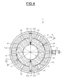
- Each of the radial portions 18 and 19 of the tie parts 14, 15 additionally comprises additional centring means 23a, 23b, 24a, 24b, numbering four, illustrated in Figure 7 .
- the additional centring means 23a, 23b, 24a, 24b comprise centring screws screwed into each of the planar axial surfaces 14a, 14b of one of the tie parts 14 and intended to come into planar contact with the planar axial surfaces 15a, 15b of the other tie part 15.
- the pins 22a, 22b and the screws 23a, 23b, 24a, 24b form means for guiding one tie part 14 with respect to the other 15 and making it possible to position the tie parts 14, 15 easily and reliably.
- the two tie parts 14, 15 are maintained in an assembled position with the aid of fixing means comprising a fixing ring 25 surrounding the tie and intended to be mounted on the upper radial shoulder 18b, 19b.
- the fixing ring 25 is intended to be clipped onto the tie 6 using clipping means 26, such as ball screws, each inserted into a hole 25a, 25b made radially in the thickness of the fixing ring 25.
- the ball screws 26 have, at one end, a shape, for example a pointed shape, matching the shape of a radial notch 18c, 19c made in the corresponding radial portion 18, 19.
- the fixing ring 25 is maintained in position around the tie 6 by cylindrical pins 27, for example numbering two, intended to be housed in a counterbore 28a, 28b, 29a, 29b made in each of the junction surfaces 14a, 14b, 15a, 15b of the two tie parts 14, 15.
- a radial through-hole 25c, 25d is made for this purpose in the fixing ring 25.
- the tie 6 is provided with additional holes (not referenced) allowing the manual screwing of the assembly consisting of the tie 6 and the fixing ring 25 by means, for example, of a pin having a diameter corresponding to the diameter of the additional holes.
- the tubular skirt 7 comprises two substantially identical skirt parts 30, 31.
- Each tubular skirt part 30, 31 takes the form of an angular portion of a part of revolution delimited by radial planes, and having a bore 30a, 31a.
- the tubular skirt 7 has a first end 7a in contact with a radial bearing surface 8f of the cylinder 8 and a second end 7b, opposite the first end 7a, in contact with the surface 4a of the structure 4 to be tensioned.
- the end 7a of the tubular skirt 7 is centred and maintained radially by the axial shoulder 8g of the base 8c of the cylinder 8.
- the tubular skirt 7 comprises two substantially semicylindrical skirt parts 30, 31, that is to say each occupying an angular sector substantially equal to 180°.
- the skirt parts 30, 31 are situated on either side of a radial parting plane P.
- the first skirt part 30 comprises two substantially planar axial surfaces 32a, 32b joined radially respectively with a substantially planar axial surface 33a, 33b of the second skirt part 31, so as to form a part of revolution of 360°.
- the axial surfaces 32a, 32b, 33a, 33b can be seen in detail in Figures 8 and 9 .
- the tubular skirt 7 comprises centring means 34a, 34b, 35a, 35b, numbering four, illustrated in Figures 7 and 9 .
- the centring means 34a, 34b, 35a, 35b comprise centring screws screwed into each of the planar axial surfaces 30a, 30b of one of the skirt parts 30 and intended to come into planar contact with the planar axial surfaces 31a, 31b of the other skirt part 31.
- the shoulder 8g of the cylinder 8 and the screws 34a, 34b, 35a, 35b form means for centring one skirt part 30 with respect to the other 31 and make it possible to position the skirt parts 30, 31 easily and reliably.
- the two skirt parts 30, 31 are maintained in an assembled position with the aid of fixing means comprising means made of magnetized material, such as magnetized annular washers 36, 37 illustrated in Figures 7 and 8 , housed in a counterbore 32c, 32d made in each of the planar axial surfaces 32a, 32b of one of the skirt parts 30.
- the magnetized annular washers 36, 37 are fixed on the corresponding planar axial surface 32a, 32b by a fixing screw 38, 39 screwed into the skirt part 30 comprising the counterbores 32c, 32d and inserted into a hole 33c, 33d parallel to the parting direction of the two skirt parts 30, 31, perpendicularly to the junction surfaces 32a, 32b, 33a, 33b, made in the thickness of the other skirt part 31.
- the fixing screws 38 and 39 also serve for centring purposes for manually placing the two skirt parts 30, 31.
- the tubular skirt 7 is made of metallic material, such as, for example, of steel, so as to be attracted by the magnets 36, 37, thus forming the means for fixing the two skirt parts 30, 31 to one another.
- Each skirt part 30, 31 additionally comprises an opening 30b, 31b in order to insert a tightening pin or tightening spanner (not shown) allowing the rotation of the nut 3, in order to tighten the nut 3 against the plate 4 to be clamped when the tension device 1 covers the end 2a of the threaded rod 2.
- the tension device 1 is assembled as follows with reference to Figures 10 to 16 .
- the tension device is assembled around the threaded rod 2 once the threaded rod 2 and the nut 3 are mounted on the structure 4 to be tensioned.
- the actuator 5 comprising the cylinder 8 and the piston 9 is mounted axially through a spacing D between the end 2a of the threaded rod 2 and a surface 40 of an external element greatly reducing the mounting space.
- the spacing D must be at least equal to the height of the actuator 5. In the example illustrated, the spacing is equal to 32 mm.
- a second step, illustrated in Figure 11 the two semicylindrical parts 14, 15 of the tie 6 are assembled radially around the threaded rod 2 and centred in position via cylindrical pins 22a, 22b and centring screws 23a, 23b, 24a, 24b (see in detail Figure 7 ).
- the tie parts 14, 15 are assembled, the tie 6 is slid axially towards the actuator 5 in order to be housed in the bore 9c of the piston 9, as illustrated in Figure 12 .
- the fixing ring 25 is then positioned around the tie parts 14, 15 against the radial shoulder 18b, 19b of the tie parts 14, 15, in order to maintain them radially in position with respect to one another.
- Figure 13 illustrates the tie 6 assembled and positioned with respect to the threaded rod 2 and to the actuator 5.
- the two semicylindrical parts 30, 31 of the tubular skirt 7 are assembled radially around the threaded rod 2, and in particular around the nut 3.
- the actuator 5 is slid towards the tubular skirt 7 in order to be centred by means of the axial shoulder 8g of the base 8c of the cylinder 8.
- the first end 7a of the tubular skirt 7 is in contact with the radial bearing surface 8f of the cylinder 8, and the second end 7b of the skirt 7, opposite the first end 7a, is in contact with the surface 4a of the structure 4 to be tensioned.
- the tension device makes it possible to prestress threaded rods even in an environment having a very small space requirement.
- the radial assembly of the tie and the tubular skirt around the threaded rod makes it possible to significantly reduce the axial dimension along the axis Y-Y of the tension device.
Landscapes
- Engineering & Computer Science (AREA)
- Mechanical Engineering (AREA)
- Actuator (AREA)
- Pistons, Piston Rings, And Cylinders (AREA)
- Hand Tools For Fitting Together And Separating, Or Other Hand Tools (AREA)
Abstract
Description
- The present invention relates to the field of devices for tensioning a rod before it is locked in position, for example by means of a nut, the invention relating in particular to devices for prestressing the threaded rods used for fixing mechanical parts to one another in the nuclear sector, the building sector, or alternatively the wind energy sector.
- Tension devices generally comprise an actuator able to exert an axial traction force on one end of a threaded rod by way of a tie. The actuator bears on a surface of a structure to be clamped via a tubular skirt surrounding one end of the threaded rod, opposite the end subjected to the axial force of the actuator. The actuator comprises a cylinder and a piston sliding in the cylinder and forming with the cylinder an annular chamber supplied with fluid under pressure.
- Such a tension device is assembled axially and generally has a large axial space requirement, such that it is not possible to use such a tension device in the event of a small space requirement between the threaded rod to be prestressed, the mechanical parts to be assembled and the outside environment.
- There is therefore a need to provide a device for tensioning a threaded rod which can be mounted on the threaded rod in the case of a very small space requirement.
- It is therefore the aim of the present invention to overcome these disadvantages.
- More particularly, the present invention aims to provide a device for tensioning a threaded rod which can be mounted on the threaded rod in the case of a very small space requirement, for example of about 32 mm for a threaded rod having a diameter of 76 mm, while maintaining a large residual prestress load, of the order of 2000 kN.
- The subject of the invention is a device for tensioning a threaded rod comprising an actuator able to exert an axial tensile force on the threaded rod with respect to a structure to be clamped, the said tension device comprising a cylinder, a piston and a tubular skirt in contact with the cylinder and a surface of the said structure to be tensioned, and a tie for transmitting the axial tensile force of the actuator towards an end of the threaded rod.
- The tie and the tubular skirt each comprise at least two semicylindrical parts each having two substantially planar axial surfaces, the two axial surfaces of one semicylindrical part being joined radially respectively with one of the two axial surfaces of the other semicylindrical part, so as to form a part of revolution.
- The tie and the tubular skirt are mounted radially around the threaded rod to be tensioned, thus allowing the assembly of the tension device even in the case of a very small space requirement.
- Advantageously, the tubular skirt comprises means for centring and means for fixing the two semicylindrical skirt parts.
- According to one embodiment, the means for centring the two skirt parts comprise centring screws screwed into each of the planar axial surfaces of one of the skirt parts and intended to come into planar contact with the planar axial surfaces of the other skirt part.
- The means for fixing the two skirt parts comprise, for example, means made of magnetized material fixed on each of the planar axial surfaces of one of the skirt parts and intended to come into planar contact with the planar axial surfaces of the other skirt part.
- The means made of magnetized material may comprise magnetized washers intended to be housed in a counterbore made in each of the planar axial surfaces of one of the skirt parts and fixed on the said skirt part using fixing means, such as, for example, fixing screws.
- According to another embodiment, the tie comprises means for centring and means for fixing the two semicylindrical tie parts.
- Advantageously, the means for centring two tie parts comprise pins arranged in holes of corresponding shape made in each of the tie parts perpendicularly to the junction surfaces and centring screws screwed into each of the planar axial surfaces of one of the tie parts and intended to come into planar contact with the planar axial surfaces of the other tie part.
- The means for fixing the two tie parts may comprise a fixing ring surrounding the tie and intended to be clipped onto the tie using clipping means.
- The fixing ring is, for example, maintained in position around the tie by cylindrical pins intended to be housed in a counterbore made in each of the junction surfaces of the two tie parts.
- According to a second aspect, the invention relates to a method for assembling a tension device as described above, in which the cylinder and the piston are mounted axially on the threaded rod to be prestressed, the two semicylindrical tie parts are assembled radially around the threaded rod and the two semicylindrical parts of the skirt are assembled radially around the threaded rod.
- Thus, the radial assembly of the tie and of the tubular skirt around the threaded rod makes it possible to significantly reduce the axial dimension along the axis Y-Y of the tension device.
- Advantageously, the fixing ring is clipped onto the tie.
- Once the two skirt parts are assembled around the threaded rod, the assembly formed by the cylinder and the piston, the two semicylindrical tie parts and the fixing ring can be slid axially by screwing the tie towards the surface of the structure to be clamped and the actuator comes into axial contact against the tubular skirt.
- The present invention will be better understood from reading the description of some embodiments, given by way of non-limiting examples and illustrated in the appended drawings:
-
Figure 1 is a perspective view of a tension device according to the invention; -
Figure 2 is a side view of the tension device according toFigure 1 ; -
Figure 3 is a view in radial section III-III of the tension device according toFigure 2 ; -
Figure 4 is a view in radial section IV-IV of the tension device according toFigure 2 ; -
Figure 5 is a view in axial section V-V of the tension device according toFigure 3 ; -
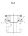
Figure 6 is a view in axial section VI-VI of the tension device according toFigure 4 ; -
Figure 7 is a view in axial section VII-VII of the tension device according toFigure 3 ; -
Figure 8 is a view in radial section VIII-VIII of the tension device according toFigure 7 ; -
Figure 9 is a view in radial section IX-IX of the tension device according toFigure 7 ; and -
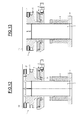
Figures 10 to 16 represent the method for assembling the tension device according to the invention. - As illustrated in the figures, the tension device, of axial axis Y-Y, referenced 1 in its entirety, is intended to axially prestress a threaded
rod 2 represented inFigures 10 to 16 . The threadedrod 2 is then blocked in position by a nut 3 bearing on asurface 4a of a structure 4 to be clamped, generally comprising at least two mechanical parts to be assembled, and represented in the form of a plate inFigures 10 to 16 . - The
tension device 1 comprises anactuator 5, atie 6 and atubular skirt 7. Theactuator 5 is able to exert an axial traction force on anend 2a of the threadedrod 2 via thetie 6. Theactuator 5 bears on thesurface 4a of the structure 4 to be clamped via thetubular skirt 7 surrounding anend 2b of the threadedrod 2, opposite theend 2a subjected to the axial force of theactuator 5. Theactuator 5 comprises acylinder 8 and apiston 9 sliding in thecylinder 8 and forming with thecylinder 8 an annular chamber (not shown) supplied with fluid under pressure. Thecylinder 8 has the general shape of an annular cup comprising an axial portion 8a having a bore 8b and a base 8c in the form of a radial portion extending inwardly from an end of the axial portion 8a and having a bore 8d. The radial portion 8c forms a radial shoulder 8c for thepiston 9. On the opposite side to theshoulder 8e, the base 8c comprises aradial bearing surface 8f in contact with anend 7a of thetubular skirt 7 opposite theend 7b in contact with thesurface 4a of the structure 4 to be tensioned. The base 8c of thecylinder 8 comprises anaxial shoulder 8g extending towards the structure 4 to be tensioned and surrounding theend 7a of thetubular skirt 7 in order to centre thecylinder 8 on thetubular skirt 7 and to maintain thetubular skirt 7 radially with respect to thecylinder 8. - The
piston 9 has an annular general shape comprising an axialtubular portion 9a and an annular collar 9b extending radially outwards from an end of the axialtubular portion 9a. The axialtubular portion 9a has abore 9c of substantially frustoconical shape and anouter surface 9d of substantially cylindrical shape in contact with the bore 8d of the base 8c of thecylinder 8. The annular collar 9b comprises an outeraxial surface 9e in contact with the bore 8b of the axial portion 8a of thecylinder 8. The annular chamber (not shown) is formed axially between the annular collar 9b of thepiston 9 and the radial base 8c of thecylinder 8, and radially between the axial portion 8a of thecylinder 8 and thetubular portion 9a of thepiston 9. The radial base 8c of thecylinder 8 comprises anannular groove 8h formed on its bore 8d and in which there is arranged aseal 10 in frictional contact with theouter surface 9d of thetubular portion 9a of thepiston 9. Analogously, the annular collar 9b of thepiston 9 comprises anannular groove 9f formed on itsouter surface 9e and in which there is arranged aseal 11 in frictional contact with the bore 8b of the axial portion 8a of thecylinder 8. Theseals - The
actuator 5 comprises means for supplying pressurized fluid which are partly represented in the figures. Aninlet 12 is formed in the base 8c of thecylinder 8, opening on one side into the annular chamber at the radial surface 8c, and at the opposite side towards the outside. Ahydraulic connection 13 is fixed to the outside of thecylinder 8 in order to supply theinlet 11 with pressurized fluid. - The
tie 6 comprises two substantiallyidentical tie parts tie part tubular portion bore outer surface bore 9c of thepiston 9, and aradial portion radial shoulder piston 9 and an upperradial shoulder - As illustrated, the
tie 6 comprises two substantiallysemicylindrical tie parts tie parts - The
first tie part 14 comprises two substantially planaraxial junction surfaces axial junction surface second tie part 15, so as to form a part of revolution of 360°. - As illustrated in detail in
Figures 3 and7 , each of theradial portions holes tie parts junction surfaces radial portions hole 20a of one of thetie parts 14 comes opposite ahole 21a of theother tie part 15. Guide means 22a, 22b, in the form of studs, pegs or pins, are respectively mounted slideably in theholes corresponding tie parts tie parts tie parts respective bore - Each of the
radial portions tie parts Figure 7 . The additional centring means 23a, 23b, 24a, 24b comprise centring screws screwed into each of the planaraxial surfaces tie parts 14 and intended to come into planar contact with the planaraxial surfaces other tie part 15. Thepins screws tie part 14 with respect to the other 15 and making it possible to position thetie parts - The two
tie parts ring 25 surrounding the tie and intended to be mounted on the upperradial shoulder ring 25 is intended to be clipped onto thetie 6 using clipping means 26, such as ball screws, each inserted into ahole ring 25. The ball screws 26 have, at one end, a shape, for example a pointed shape, matching the shape of aradial notch 18c, 19c made in the correspondingradial portion ring 25 is maintained in position around thetie 6 bycylindrical pins 27, for example numbering two, intended to be housed in acounterbore junction surfaces tie parts hole 25c, 25d is made for this purpose in the fixingring 25. When the fixingring 25 is assembled on thetie 6, the diameter of the fixingring 25 is substantially equal to the diameter of theradial portions - The
tie 6 is provided with additional holes (not referenced) allowing the manual screwing of the assembly consisting of thetie 6 and the fixingring 25 by means, for example, of a pin having a diameter corresponding to the diameter of the additional holes. - The
tubular skirt 7 comprises two substantiallyidentical skirt parts tubular skirt part bore tubular skirt 7 has afirst end 7a in contact with aradial bearing surface 8f of thecylinder 8 and asecond end 7b, opposite thefirst end 7a, in contact with thesurface 4a of the structure 4 to be tensioned. Theend 7a of thetubular skirt 7 is centred and maintained radially by theaxial shoulder 8g of the base 8c of thecylinder 8. - As illustrated, the
tubular skirt 7 comprises two substantiallysemicylindrical skirt parts skirt parts - The
first skirt part 30 comprises two substantially planaraxial surfaces axial surface second skirt part 31, so as to form a part of revolution of 360°. Theaxial surfaces Figures 8 and 9 . - As illustrated in detail in
Figures 7 to 9 , thetubular skirt 7 comprises centring means 34a, 34b, 35a, 35b, numbering four, illustrated inFigures 7 and9 . The centring means 34a, 34b, 35a, 35b comprise centring screws screwed into each of the planaraxial surfaces skirt parts 30 and intended to come into planar contact with the planaraxial surfaces other skirt part 31. Theshoulder 8g of thecylinder 8 and thescrews skirt part 30 with respect to the other 31 and make it possible to position theskirt parts - The two
skirt parts annular washers Figures 7 and8 , housed in acounterbore axial surfaces skirt parts 30. The magnetizedannular washers axial surface screw skirt part 30 comprising thecounterbores hole skirt parts junction surfaces other skirt part 31. The fixing screws 38 and 39 also serve for centring purposes for manually placing the twoskirt parts - The
tubular skirt 7 is made of metallic material, such as, for example, of steel, so as to be attracted by themagnets skirt parts - Each
skirt part opening tension device 1 covers theend 2a of the threadedrod 2. - The
tension device 1 is assembled as follows with reference toFigures 10 to 16 . The tension device is assembled around the threadedrod 2 once the threadedrod 2 and the nut 3 are mounted on the structure 4 to be tensioned. - In a first step, illustrated in
Figure 10 , theactuator 5 comprising thecylinder 8 and thepiston 9 is mounted axially through a spacing D between theend 2a of the threadedrod 2 and asurface 40 of an external element greatly reducing the mounting space. For example, the spacing D must be at least equal to the height of theactuator 5. In the example illustrated, the spacing is equal to 32 mm. - In a second step, illustrated in
Figure 11 , the twosemicylindrical parts tie 6 are assembled radially around the threadedrod 2 and centred in position viacylindrical pins centring screws Figure 7 ). Once thetie parts tie 6 is slid axially towards theactuator 5 in order to be housed in thebore 9c of thepiston 9, as illustrated inFigure 12 . The fixingring 25 is then positioned around thetie parts radial shoulder tie parts Figure 13 illustrates thetie 6 assembled and positioned with respect to the threadedrod 2 and to theactuator 5. - In the step illustrated in
Figure 14 , the twosemicylindrical parts tubular skirt 7 are assembled radially around the threadedrod 2, and in particular around the nut 3. In the step illustrated inFigure 15 , theactuator 5 is slid towards thetubular skirt 7 in order to be centred by means of theaxial shoulder 8g of the base 8c of thecylinder 8. Thefirst end 7a of thetubular skirt 7 is in contact with theradial bearing surface 8f of thecylinder 8, and thesecond end 7b of theskirt 7, opposite thefirst end 7a, is in contact with thesurface 4a of the structure 4 to be tensioned. - Finally, during a final step illustrated in
Figure 16 , the assembly formed by thetie 6 and the fixingring 25 is made to move helically towards theactuator 5 so as to be positioned ready to be used to tension the threadedrod 2. - By virtue of the invention described, the tension device makes it possible to prestress threaded rods even in an environment having a very small space requirement. Specifically, the radial assembly of the tie and the tubular skirt around the threaded rod makes it possible to significantly reduce the axial dimension along the axis Y-Y of the tension device.
Claims (13)
- Device (1) for tensioning a threaded rod (2) comprising an actuator (5) able to exert an axial tensile force on the threaded rod (2) with respect to a structure (4) to be tensioned, the said tension device (1) comprising a cylinder (8), a piston (9), a tubular skirt (7) in contact with the cylinder (8) and a surface (4a) of the said structure (4) to be tensioned, and a tie (6) for transmitting the axial tensile force of the actuator (5) towards an end (2a) of the threaded rod (2), characterized in that the tie (6) and the tubular skirt (7) each comprise at least two semicylindrical parts (14, 15; 30, 31) each having two substantially planar axial surfaces (14a, 14b, 15a, 15b; 32a, 32b, 33a, 33b), the two axial surfaces (14a, 14b; 32a, 32b) of one semicylindrical part (14, 30) being joined radially respectively with one of the two axial surfaces (15a, 15b; 33a, 33b) of the other semicylindrical part (15, 31), so as to form a part of revolution.
- Tension device according to Claim 1, in which the tubular skirt (7) comprises means (7a, 34a, 34b, 35a, 35b) for centring and means (36, 37, 38, 39) for fixing the two semicylindrical skirt parts (30, 31).
- Tension device according to Claim 2, in which the means (34a, 34b, 35a, 35b) for centring the two skirt parts (30, 31) comprise centring screws screwed into each of the planar axial surfaces (32a, 32b) of one of the skirt parts (30) and intended to come into planar contact with the planar axial surfaces (33a, 33b) of the other skirt part (31).
- Tension device according to any one of the preceding claims, in which the means (36, 37, 38, 39) for fixing the two skirt parts (30, 31) comprise means (36, 37) made of magnetized material fixed on each of the planar axial surfaces (32a, 32b) of one of the skirt parts (30) and intended to come into planar contact with the planar axial surfaces (33a, 33b) of the other skirt part (31).
- Tension device according to Claim 4, in which means (36, 37) made of magnetized material comprise magnetized washers intended to be housed in a counterbore (32c, 32d) made in each of the planar axial surfaces (32a, 32b) of one of the skirt parts (30) and fixed on the said skirt part (30) using fixing means (38, 39).
- Tension device according to Claim 5, in which the means (38, 39) for fixing the magnetized washers (36, 37) on the planar axial surfaces (32a, 32b) of the corresponding skirt part (30) comprise fixing screws.
- Tension device according to any one of the preceding claims, in which the tie (6) comprises means (22a, 22b, 23a, 23b, 24a, 24b) for centring and means (25, 26, 27) for fixing the two semicylindrical tie parts (14, 15).
- Tension device according to Claim 7, in which the means for centring two tie parts (14, 15) comprise pins (22a, 22b) arranged in holes (20a, 20b, 21a, 21b) of corresponding shape made in each of the tie parts (14, 15) perpendicularly to the junction surfaces (14a, 14b, 15a, 15b) and centring screws (23a, 23b, 24a, 24b) screwed into each of the planar axial surfaces (14a, 14b) of one of the tie parts (14) and intended to come into planar contact with the planar axial surfaces (15a, 15b) of the other tie part (15).
- Tension device according to either of Claims 7 and 8, in which the means for fixing the two tie parts (14, 15) comprise a fixing ring (25) surrounding the tie (6) and intended to be clipped onto the tie (6) using clipping means (26).
- Tension device according to Claim 9, in which the fixing ring (25) is maintained in position around the tie (6) by cylindrical pins (27) intended to be housed in a counterbore (28a, 28b, 29a, 29b) made in each of the junction surfaces (14a, 14b, 15a, 15b) of the two tie parts (14, 15).
- Method for assembling a tension device (1) according to any one of the preceding claims, in which the cylinder (8) and the piston (9) are mounted axially on the threaded rod (2) to be prestressed, the two semicylindrical tie parts (14, 15) are assembled radially around the threaded rod (2) and the two semicylindrical parts (30, 31) of the skirt are assembled radially around the threaded rod (2).
- Assembly method according to Claims 11, in which the fixing ring (25) is clipped onto the tie (6).
- Assembly method according to Claim 12, in which, once the two skirt parts (30, 31) are assembled around the threaded rod (2), the assembly formed by the cylinder (8) and the piston (9), the two semicylindrical tie parts (14, 15) and the fixing ring (25) is slid axially towards the surface (4a) of the structure (4) to be tensioned.
Applications Claiming Priority (1)
| Application Number | Priority Date | Filing Date | Title |
|---|---|---|---|
| FR1257208A FR2993807B1 (en) | 2012-07-25 | 2012-07-25 | VOLTAGE DEVICE FOR PRE-STRESSING AN ASSEMBLY USING A THREADED ROD AND METHOD OF ASSEMBLING THE VOLTAGE DEVICE |
Publications (2)
| Publication Number | Publication Date |
|---|---|
| EP2689887A1 true EP2689887A1 (en) | 2014-01-29 |
| EP2689887B1 EP2689887B1 (en) | 2015-07-15 |
Family
ID=47178062
Family Applications (1)
| Application Number | Title | Priority Date | Filing Date |
|---|---|---|---|
| EP13177281.6A Active EP2689887B1 (en) | 2012-07-25 | 2013-07-19 | Tension device for prestressing an assembly by means of a threaded rod, and method for assembling the tension device |
Country Status (4)
| Country | Link |
|---|---|
| EP (1) | EP2689887B1 (en) |
| CN (1) | CN103573783B (en) |
| FR (1) | FR2993807B1 (en) |
| RU (1) | RU2013134938A (en) |
Citations (5)
| Publication number | Priority date | Publication date | Assignee | Title |
|---|---|---|---|---|
| GB2193549A (en) * | 1986-08-08 | 1988-02-10 | Hydra Tight Ltd | Bolt tensioner |
| EP0922527A1 (en) * | 1997-12-09 | 1999-06-16 | Hydra-Tight Limited | Tensioning device |
| DE102007015975A1 (en) * | 2007-03-31 | 2008-10-23 | As Tech Industrie- Und Spannhydraulik Gmbh | Hydraulic clamping device for clamping screw, has traction element with parts which are radially movable and arranged in direction of cylinder and movement axle, where each radially movable arranged part is fixed in position |
| US20090293418A1 (en) * | 2008-05-30 | 2009-12-03 | Gordon Britton | Foundation Bolt Tensioner |
| US20110192257A1 (en) * | 2010-02-09 | 2011-08-11 | Titan Technologies International, Inc. | Hydraulic Bolt Tensioner and Nut |
Family Cites Families (4)
| Publication number | Priority date | Publication date | Assignee | Title |
|---|---|---|---|---|
| US4416574A (en) * | 1979-06-11 | 1983-11-22 | Klimowicz Jerome R | Multiple piece bolt-type fastener |
| US4484849A (en) * | 1980-12-19 | 1984-11-27 | Klimowicz Jerome R | Multiple piece bolt-type fastener |
| FR2841304B1 (en) * | 2002-06-20 | 2007-01-05 | Skf Ab | VOLTAGE DEVICE FOR PRECONTRATING ROD AND ASSOCIATED VOLTAGE METHOD |
| CN201027729Y (en) * | 2007-03-29 | 2008-02-27 | 西门子(中国)有限公司 | Mechanical linkage components and adjustable mechanical mounts |
-
2012
- 2012-07-25 FR FR1257208A patent/FR2993807B1/en not_active Expired - Fee Related
-
2013
- 2013-07-19 EP EP13177281.6A patent/EP2689887B1/en active Active
- 2013-07-24 RU RU2013134938/12A patent/RU2013134938A/en not_active Application Discontinuation
- 2013-07-25 CN CN201310442455.4A patent/CN103573783B/en active Active
Patent Citations (5)
| Publication number | Priority date | Publication date | Assignee | Title |
|---|---|---|---|---|
| GB2193549A (en) * | 1986-08-08 | 1988-02-10 | Hydra Tight Ltd | Bolt tensioner |
| EP0922527A1 (en) * | 1997-12-09 | 1999-06-16 | Hydra-Tight Limited | Tensioning device |
| DE102007015975A1 (en) * | 2007-03-31 | 2008-10-23 | As Tech Industrie- Und Spannhydraulik Gmbh | Hydraulic clamping device for clamping screw, has traction element with parts which are radially movable and arranged in direction of cylinder and movement axle, where each radially movable arranged part is fixed in position |
| US20090293418A1 (en) * | 2008-05-30 | 2009-12-03 | Gordon Britton | Foundation Bolt Tensioner |
| US20110192257A1 (en) * | 2010-02-09 | 2011-08-11 | Titan Technologies International, Inc. | Hydraulic Bolt Tensioner and Nut |
Also Published As
| Publication number | Publication date |
|---|---|
| CN103573783B (en) | 2017-04-12 |
| EP2689887B1 (en) | 2015-07-15 |
| FR2993807A1 (en) | 2014-01-31 |
| CN103573783A (en) | 2014-02-12 |
| RU2013134938A (en) | 2015-01-27 |
| FR2993807B1 (en) | 2014-08-29 |
Similar Documents
| Publication | Publication Date | Title |
|---|---|---|
| US10570934B2 (en) | Fluidic cylinder | |
| EP3310533B1 (en) | Screw tensioning device | |
| US20140338501A1 (en) | Tensioning apparatus | |
| US20070044655A1 (en) | Removable end plug | |
| CN104697852A (en) | Rock sample fixing device for limit tension and compression cycle test of spring assembly | |
| CN106041503A (en) | Tensioning device for pre-stressing assembly with threaded rod | |
| US9631494B2 (en) | Rotor structure including an internal hydraulic tension device | |
| KR102079670B1 (en) | Hydraulic cylinder | |
| KR101802323B1 (en) | Bearing | |
| CN104677727A (en) | Spring component limiting rock sample fixing device for hydraulic spring type direct tensile test | |
| US9375815B2 (en) | Tension device for prestressing an assembly by means of a threaded rod, and method for assembling the tension device | |
| EP2689887B1 (en) | Tension device for prestressing an assembly by means of a threaded rod, and method for assembling the tension device | |
| US10428791B2 (en) | Wind turbine rotor blade | |
| US10245689B2 (en) | Rod tensioning device and assembly process of such a device on a rod | |
| US11635163B2 (en) | Hydraulic component with a component housing and a connection block | |
| KR102015494B1 (en) | Hydraulic cylinder | |
| CN108061647B (en) | Multifunctional self-balancing platform for static test | |
| KR101356806B1 (en) | Device for tensioning threaded rods | |
| US8128062B2 (en) | Valve with self-aligning shaft seal | |
| US9377056B2 (en) | Bearing stack for a down-hole drilling motor | |
| KR102083921B1 (en) | Hydraulic cylinder | |
| CN110789735B (en) | Force-controllable double-beam clamping device | |
| EP3063420B1 (en) | Method for preventing fretting, tool for deforming a contact surface and use of the tool | |
| CN107289134A (en) | A mechanical seal preload adjustment device | |
| JP6353206B2 (en) | Holder device with aligning mechanism, radial bearing device and bolt with aligning mechanism |
Legal Events
| Date | Code | Title | Description |
|---|---|---|---|
| PUAI | Public reference made under article 153(3) epc to a published international application that has entered the european phase |
Free format text: ORIGINAL CODE: 0009012 |
|
| AK | Designated contracting states |
Kind code of ref document: A1 Designated state(s): AL AT BE BG CH CY CZ DE DK EE ES FI FR GB GR HR HU IE IS IT LI LT LU LV MC MK MT NL NO PL PT RO RS SE SI SK SM TR |
|
| AX | Request for extension of the european patent |
Extension state: BA ME |
|
| 17P | Request for examination filed |
Effective date: 20140715 |
|
| GRAP | Despatch of communication of intention to grant a patent |
Free format text: ORIGINAL CODE: EPIDOSNIGR1 |
|
| RIC1 | Information provided on ipc code assigned before grant |
Ipc: F16B 37/08 20060101ALI20150121BHEP Ipc: B25B 29/02 20060101ALI20150121BHEP Ipc: F16B 31/04 20060101ALI20150121BHEP Ipc: B23P 19/06 20060101AFI20150121BHEP |
|
| INTG | Intention to grant announced |
Effective date: 20150220 |
|
| GRAS | Grant fee paid |
Free format text: ORIGINAL CODE: EPIDOSNIGR3 |
|
| GRAA | (expected) grant |
Free format text: ORIGINAL CODE: 0009210 |
|
| AK | Designated contracting states |
Kind code of ref document: B1 Designated state(s): AL AT BE BG CH CY CZ DE DK EE ES FI FR GB GR HR HU IE IS IT LI LT LU LV MC MK MT NL NO PL PT RO RS SE SI SK SM TR |
|
| REG | Reference to a national code |
Ref country code: CH Ref legal event code: EP Ref country code: GB Ref legal event code: FG4D |
|
| REG | Reference to a national code |
Ref country code: IE Ref legal event code: FG4D |
|
| REG | Reference to a national code |
Ref country code: AT Ref legal event code: REF Ref document number: 736529 Country of ref document: AT Kind code of ref document: T Effective date: 20150815 |
|
| REG | Reference to a national code |
Ref country code: DE Ref legal event code: R096 Ref document number: 602013002282 Country of ref document: DE |
|
| REG | Reference to a national code |
Ref country code: AT Ref legal event code: MK05 Ref document number: 736529 Country of ref document: AT Kind code of ref document: T Effective date: 20150715 |
|
| REG | Reference to a national code |
Ref country code: NL Ref legal event code: MP Effective date: 20150715 |
|
| REG | Reference to a national code |
Ref country code: LT Ref legal event code: MG4D |
|
| PG25 | Lapsed in a contracting state [announced via postgrant information from national office to epo] |
Ref country code: GR Free format text: LAPSE BECAUSE OF FAILURE TO SUBMIT A TRANSLATION OF THE DESCRIPTION OR TO PAY THE FEE WITHIN THE PRESCRIBED TIME-LIMIT Effective date: 20151016 Ref country code: LV Free format text: LAPSE BECAUSE OF FAILURE TO SUBMIT A TRANSLATION OF THE DESCRIPTION OR TO PAY THE FEE WITHIN THE PRESCRIBED TIME-LIMIT Effective date: 20150715 Ref country code: LT Free format text: LAPSE BECAUSE OF FAILURE TO SUBMIT A TRANSLATION OF THE DESCRIPTION OR TO PAY THE FEE WITHIN THE PRESCRIBED TIME-LIMIT Effective date: 20150715 Ref country code: NO Free format text: LAPSE BECAUSE OF FAILURE TO SUBMIT A TRANSLATION OF THE DESCRIPTION OR TO PAY THE FEE WITHIN THE PRESCRIBED TIME-LIMIT Effective date: 20151015 Ref country code: FI Free format text: LAPSE BECAUSE OF FAILURE TO SUBMIT A TRANSLATION OF THE DESCRIPTION OR TO PAY THE FEE WITHIN THE PRESCRIBED TIME-LIMIT Effective date: 20150715 |
|
| PG25 | Lapsed in a contracting state [announced via postgrant information from national office to epo] |
Ref country code: ES Free format text: LAPSE BECAUSE OF FAILURE TO SUBMIT A TRANSLATION OF THE DESCRIPTION OR TO PAY THE FEE WITHIN THE PRESCRIBED TIME-LIMIT Effective date: 20150715 Ref country code: AT Free format text: LAPSE BECAUSE OF FAILURE TO SUBMIT A TRANSLATION OF THE DESCRIPTION OR TO PAY THE FEE WITHIN THE PRESCRIBED TIME-LIMIT Effective date: 20150715 Ref country code: SE Free format text: LAPSE BECAUSE OF FAILURE TO SUBMIT A TRANSLATION OF THE DESCRIPTION OR TO PAY THE FEE WITHIN THE PRESCRIBED TIME-LIMIT Effective date: 20150715 Ref country code: PL Free format text: LAPSE BECAUSE OF FAILURE TO SUBMIT A TRANSLATION OF THE DESCRIPTION OR TO PAY THE FEE WITHIN THE PRESCRIBED TIME-LIMIT Effective date: 20150715 Ref country code: PT Free format text: LAPSE BECAUSE OF FAILURE TO SUBMIT A TRANSLATION OF THE DESCRIPTION OR TO PAY THE FEE WITHIN THE PRESCRIBED TIME-LIMIT Effective date: 20151116 Ref country code: HR Free format text: LAPSE BECAUSE OF FAILURE TO SUBMIT A TRANSLATION OF THE DESCRIPTION OR TO PAY THE FEE WITHIN THE PRESCRIBED TIME-LIMIT Effective date: 20150715 Ref country code: RS Free format text: LAPSE BECAUSE OF FAILURE TO SUBMIT A TRANSLATION OF THE DESCRIPTION OR TO PAY THE FEE WITHIN THE PRESCRIBED TIME-LIMIT Effective date: 20150715 |
|
| REG | Reference to a national code |
Ref country code: DE Ref legal event code: R097 Ref document number: 602013002282 Country of ref document: DE |
|
| REG | Reference to a national code |
Ref country code: IE Ref legal event code: MM4A |
|
| PG25 | Lapsed in a contracting state [announced via postgrant information from national office to epo] |
Ref country code: CZ Free format text: LAPSE BECAUSE OF FAILURE TO SUBMIT A TRANSLATION OF THE DESCRIPTION OR TO PAY THE FEE WITHIN THE PRESCRIBED TIME-LIMIT Effective date: 20150715 Ref country code: MC Free format text: LAPSE BECAUSE OF FAILURE TO SUBMIT A TRANSLATION OF THE DESCRIPTION OR TO PAY THE FEE WITHIN THE PRESCRIBED TIME-LIMIT Effective date: 20150715 Ref country code: SK Free format text: LAPSE BECAUSE OF FAILURE TO SUBMIT A TRANSLATION OF THE DESCRIPTION OR TO PAY THE FEE WITHIN THE PRESCRIBED TIME-LIMIT Effective date: 20150715 Ref country code: EE Free format text: LAPSE BECAUSE OF FAILURE TO SUBMIT A TRANSLATION OF THE DESCRIPTION OR TO PAY THE FEE WITHIN THE PRESCRIBED TIME-LIMIT Effective date: 20150715 Ref country code: IT Free format text: LAPSE BECAUSE OF FAILURE TO SUBMIT A TRANSLATION OF THE DESCRIPTION OR TO PAY THE FEE WITHIN THE PRESCRIBED TIME-LIMIT Effective date: 20150715 Ref country code: DK Free format text: LAPSE BECAUSE OF FAILURE TO SUBMIT A TRANSLATION OF THE DESCRIPTION OR TO PAY THE FEE WITHIN THE PRESCRIBED TIME-LIMIT Effective date: 20150715 |
|
| PLBE | No opposition filed within time limit |
Free format text: ORIGINAL CODE: 0009261 |
|
| STAA | Information on the status of an ep patent application or granted ep patent |
Free format text: STATUS: NO OPPOSITION FILED WITHIN TIME LIMIT |
|
| PG25 | Lapsed in a contracting state [announced via postgrant information from national office to epo] |
Ref country code: RO Free format text: LAPSE BECAUSE OF FAILURE TO SUBMIT A TRANSLATION OF THE DESCRIPTION OR TO PAY THE FEE WITHIN THE PRESCRIBED TIME-LIMIT Effective date: 20150715 |
|
| 26N | No opposition filed |
Effective date: 20160418 |
|
| PG25 | Lapsed in a contracting state [announced via postgrant information from national office to epo] |
Ref country code: IS Free format text: LAPSE BECAUSE OF FAILURE TO SUBMIT A TRANSLATION OF THE DESCRIPTION OR TO PAY THE FEE WITHIN THE PRESCRIBED TIME-LIMIT Effective date: 20150715 |
|
| REG | Reference to a national code |
Ref country code: FR Ref legal event code: PLFP Year of fee payment: 4 |
|
| PG25 | Lapsed in a contracting state [announced via postgrant information from national office to epo] |
Ref country code: IE Free format text: LAPSE BECAUSE OF NON-PAYMENT OF DUE FEES Effective date: 20150719 |
|
| PG25 | Lapsed in a contracting state [announced via postgrant information from national office to epo] |
Ref country code: SI Free format text: LAPSE BECAUSE OF FAILURE TO SUBMIT A TRANSLATION OF THE DESCRIPTION OR TO PAY THE FEE WITHIN THE PRESCRIBED TIME-LIMIT Effective date: 20150715 |
|
| PG25 | Lapsed in a contracting state [announced via postgrant information from national office to epo] |
Ref country code: BE Free format text: LAPSE BECAUSE OF FAILURE TO SUBMIT A TRANSLATION OF THE DESCRIPTION OR TO PAY THE FEE WITHIN THE PRESCRIBED TIME-LIMIT Effective date: 20150715 |
|
| REG | Reference to a national code |
Ref country code: CH Ref legal event code: PL |
|
| PG25 | Lapsed in a contracting state [announced via postgrant information from national office to epo] |
Ref country code: MT Free format text: LAPSE BECAUSE OF FAILURE TO SUBMIT A TRANSLATION OF THE DESCRIPTION OR TO PAY THE FEE WITHIN THE PRESCRIBED TIME-LIMIT Effective date: 20150715 |
|
| PG25 | Lapsed in a contracting state [announced via postgrant information from national office to epo] |
Ref country code: CH Free format text: LAPSE BECAUSE OF NON-PAYMENT OF DUE FEES Effective date: 20160731 Ref country code: LI Free format text: LAPSE BECAUSE OF NON-PAYMENT OF DUE FEES Effective date: 20160731 |
|
| PG25 | Lapsed in a contracting state [announced via postgrant information from national office to epo] |
Ref country code: HU Free format text: LAPSE BECAUSE OF FAILURE TO SUBMIT A TRANSLATION OF THE DESCRIPTION OR TO PAY THE FEE WITHIN THE PRESCRIBED TIME-LIMIT; INVALID AB INITIO Effective date: 20130719 Ref country code: BG Free format text: LAPSE BECAUSE OF FAILURE TO SUBMIT A TRANSLATION OF THE DESCRIPTION OR TO PAY THE FEE WITHIN THE PRESCRIBED TIME-LIMIT Effective date: 20150715 |
|
| PG25 | Lapsed in a contracting state [announced via postgrant information from national office to epo] |
Ref country code: CY Free format text: LAPSE BECAUSE OF FAILURE TO SUBMIT A TRANSLATION OF THE DESCRIPTION OR TO PAY THE FEE WITHIN THE PRESCRIBED TIME-LIMIT Effective date: 20150715 Ref country code: NL Free format text: LAPSE BECAUSE OF FAILURE TO SUBMIT A TRANSLATION OF THE DESCRIPTION OR TO PAY THE FEE WITHIN THE PRESCRIBED TIME-LIMIT Effective date: 20150715 |
|
| REG | Reference to a national code |
Ref country code: FR Ref legal event code: PLFP Year of fee payment: 5 |
|
| PG25 | Lapsed in a contracting state [announced via postgrant information from national office to epo] |
Ref country code: LU Free format text: LAPSE BECAUSE OF NON-PAYMENT OF DUE FEES Effective date: 20150719 |
|
| PG25 | Lapsed in a contracting state [announced via postgrant information from national office to epo] |
Ref country code: SM Free format text: LAPSE BECAUSE OF FAILURE TO SUBMIT A TRANSLATION OF THE DESCRIPTION OR TO PAY THE FEE WITHIN THE PRESCRIBED TIME-LIMIT Effective date: 20150715 |
|
| PG25 | Lapsed in a contracting state [announced via postgrant information from national office to epo] |
Ref country code: MK Free format text: LAPSE BECAUSE OF FAILURE TO SUBMIT A TRANSLATION OF THE DESCRIPTION OR TO PAY THE FEE WITHIN THE PRESCRIBED TIME-LIMIT Effective date: 20150715 Ref country code: TR Free format text: LAPSE BECAUSE OF FAILURE TO SUBMIT A TRANSLATION OF THE DESCRIPTION OR TO PAY THE FEE WITHIN THE PRESCRIBED TIME-LIMIT Effective date: 20150715 |
|
| REG | Reference to a national code |
Ref country code: FR Ref legal event code: PLFP Year of fee payment: 6 |
|
| PG25 | Lapsed in a contracting state [announced via postgrant information from national office to epo] |
Ref country code: AL Free format text: LAPSE BECAUSE OF FAILURE TO SUBMIT A TRANSLATION OF THE DESCRIPTION OR TO PAY THE FEE WITHIN THE PRESCRIBED TIME-LIMIT Effective date: 20150715 |
|
| P01 | Opt-out of the competence of the unified patent court (upc) registered |
Effective date: 20230513 |
|
| PGFP | Annual fee paid to national office [announced via postgrant information from national office to epo] |
Ref country code: DE Payment date: 20250728 Year of fee payment: 13 |
|
| PGFP | Annual fee paid to national office [announced via postgrant information from national office to epo] |
Ref country code: GB Payment date: 20250722 Year of fee payment: 13 |
|
| PGFP | Annual fee paid to national office [announced via postgrant information from national office to epo] |
Ref country code: FR Payment date: 20250725 Year of fee payment: 13 |