EP2689756A1 - Localized microclimate management - Google Patents
Localized microclimate management Download PDFInfo
- Publication number
- EP2689756A1 EP2689756A1 EP13190107.6A EP13190107A EP2689756A1 EP 2689756 A1 EP2689756 A1 EP 2689756A1 EP 13190107 A EP13190107 A EP 13190107A EP 2689756 A1 EP2689756 A1 EP 2689756A1
- Authority
- EP
- European Patent Office
- Prior art keywords
- occupant support
- straps
- heat flow
- pressure
- mattress
- Prior art date
- Legal status (The legal status is an assumption and is not a legal conclusion. Google has not performed a legal analysis and makes no representation as to the accuracy of the status listed.)
- Granted
Links
Images


Classifications
-
- A—HUMAN NECESSITIES
- A47—FURNITURE; DOMESTIC ARTICLES OR APPLIANCES; COFFEE MILLS; SPICE MILLS; SUCTION CLEANERS IN GENERAL
- A47C—CHAIRS; SOFAS; BEDS
- A47C21/00—Attachments for beds, e.g. sheet holders, bed-cover holders; Ventilating, cooling or heating means in connection with bedsteads or mattresses
- A47C21/04—Devices for ventilating, cooling or heating
- A47C21/042—Devices for ventilating, cooling or heating for ventilating or cooling
- A47C21/044—Devices for ventilating, cooling or heating for ventilating or cooling with active means, e.g. by using air blowers or liquid pumps
-
- A—HUMAN NECESSITIES
- A61—MEDICAL OR VETERINARY SCIENCE; HYGIENE
- A61F—FILTERS IMPLANTABLE INTO BLOOD VESSELS; PROSTHESES; DEVICES PROVIDING PATENCY TO, OR PREVENTING COLLAPSING OF, TUBULAR STRUCTURES OF THE BODY, e.g. STENTS; ORTHOPAEDIC, NURSING OR CONTRACEPTIVE DEVICES; FOMENTATION; TREATMENT OR PROTECTION OF EYES OR EARS; BANDAGES, DRESSINGS OR ABSORBENT PADS; FIRST-AID KITS
- A61F7/00—Heating or cooling appliances for medical or therapeutic treatment of the human body
- A61F7/02—Compresses or poultices for effecting heating or cooling
-
- A—HUMAN NECESSITIES
- A47—FURNITURE; DOMESTIC ARTICLES OR APPLIANCES; COFFEE MILLS; SPICE MILLS; SUCTION CLEANERS IN GENERAL
- A47C—CHAIRS; SOFAS; BEDS
- A47C21/00—Attachments for beds, e.g. sheet holders, bed-cover holders; Ventilating, cooling or heating means in connection with bedsteads or mattresses
- A47C21/04—Devices for ventilating, cooling or heating
- A47C21/042—Devices for ventilating, cooling or heating for ventilating or cooling
- A47C21/046—Devices for ventilating, cooling or heating for ventilating or cooling without active means, e.g. with openings or heat conductors
-
- A—HUMAN NECESSITIES
- A47—FURNITURE; DOMESTIC ARTICLES OR APPLIANCES; COFFEE MILLS; SPICE MILLS; SUCTION CLEANERS IN GENERAL
- A47C—CHAIRS; SOFAS; BEDS
- A47C21/00—Attachments for beds, e.g. sheet holders, bed-cover holders; Ventilating, cooling or heating means in connection with bedsteads or mattresses
- A47C21/04—Devices for ventilating, cooling or heating
- A47C21/048—Devices for ventilating, cooling or heating for heating
-
- A—HUMAN NECESSITIES
- A61—MEDICAL OR VETERINARY SCIENCE; HYGIENE
- A61F—FILTERS IMPLANTABLE INTO BLOOD VESSELS; PROSTHESES; DEVICES PROVIDING PATENCY TO, OR PREVENTING COLLAPSING OF, TUBULAR STRUCTURES OF THE BODY, e.g. STENTS; ORTHOPAEDIC, NURSING OR CONTRACEPTIVE DEVICES; FOMENTATION; TREATMENT OR PROTECTION OF EYES OR EARS; BANDAGES, DRESSINGS OR ABSORBENT PADS; FIRST-AID KITS
- A61F7/00—Heating or cooling appliances for medical or therapeutic treatment of the human body
- A61F7/10—Cooling bags, e.g. ice-bags
-
- A—HUMAN NECESSITIES
- A61—MEDICAL OR VETERINARY SCIENCE; HYGIENE
- A61F—FILTERS IMPLANTABLE INTO BLOOD VESSELS; PROSTHESES; DEVICES PROVIDING PATENCY TO, OR PREVENTING COLLAPSING OF, TUBULAR STRUCTURES OF THE BODY, e.g. STENTS; ORTHOPAEDIC, NURSING OR CONTRACEPTIVE DEVICES; FOMENTATION; TREATMENT OR PROTECTION OF EYES OR EARS; BANDAGES, DRESSINGS OR ABSORBENT PADS; FIRST-AID KITS
- A61F7/00—Heating or cooling appliances for medical or therapeutic treatment of the human body
- A61F2007/0001—Body part
-
- A—HUMAN NECESSITIES
- A61—MEDICAL OR VETERINARY SCIENCE; HYGIENE
- A61F—FILTERS IMPLANTABLE INTO BLOOD VESSELS; PROSTHESES; DEVICES PROVIDING PATENCY TO, OR PREVENTING COLLAPSING OF, TUBULAR STRUCTURES OF THE BODY, e.g. STENTS; ORTHOPAEDIC, NURSING OR CONTRACEPTIVE DEVICES; FOMENTATION; TREATMENT OR PROTECTION OF EYES OR EARS; BANDAGES, DRESSINGS OR ABSORBENT PADS; FIRST-AID KITS
- A61F7/00—Heating or cooling appliances for medical or therapeutic treatment of the human body
- A61F2007/0093—Heating or cooling appliances for medical or therapeutic treatment of the human body programmed
-
- A—HUMAN NECESSITIES
- A61—MEDICAL OR VETERINARY SCIENCE; HYGIENE
- A61F—FILTERS IMPLANTABLE INTO BLOOD VESSELS; PROSTHESES; DEVICES PROVIDING PATENCY TO, OR PREVENTING COLLAPSING OF, TUBULAR STRUCTURES OF THE BODY, e.g. STENTS; ORTHOPAEDIC, NURSING OR CONTRACEPTIVE DEVICES; FOMENTATION; TREATMENT OR PROTECTION OF EYES OR EARS; BANDAGES, DRESSINGS OR ABSORBENT PADS; FIRST-AID KITS
- A61F7/00—Heating or cooling appliances for medical or therapeutic treatment of the human body
- A61F2007/0095—Heating or cooling appliances for medical or therapeutic treatment of the human body with a temperature indicator
-
- A—HUMAN NECESSITIES
- A61—MEDICAL OR VETERINARY SCIENCE; HYGIENE
- A61F—FILTERS IMPLANTABLE INTO BLOOD VESSELS; PROSTHESES; DEVICES PROVIDING PATENCY TO, OR PREVENTING COLLAPSING OF, TUBULAR STRUCTURES OF THE BODY, e.g. STENTS; ORTHOPAEDIC, NURSING OR CONTRACEPTIVE DEVICES; FOMENTATION; TREATMENT OR PROTECTION OF EYES OR EARS; BANDAGES, DRESSINGS OR ABSORBENT PADS; FIRST-AID KITS
- A61F7/00—Heating or cooling appliances for medical or therapeutic treatment of the human body
- A61F7/02—Compresses or poultices for effecting heating or cooling
- A61F2007/0244—Compresses or poultices for effecting heating or cooling with layers
- A61F2007/0246—Compresses or poultices for effecting heating or cooling with layers with a layer having high heat transfer capability
-
- A—HUMAN NECESSITIES
- A61—MEDICAL OR VETERINARY SCIENCE; HYGIENE
- A61G—TRANSPORT, PERSONAL CONVEYANCES, OR ACCOMMODATION SPECIALLY ADAPTED FOR PATIENTS OR DISABLED PERSONS; OPERATING TABLES OR CHAIRS; CHAIRS FOR DENTISTRY; FUNERAL DEVICES
- A61G7/00—Beds specially adapted for nursing; Devices for lifting patients or disabled persons
- A61G7/05—Parts, details or accessories of beds
- A61G7/057—Arrangements for preventing bed-sores or for supporting patients with burns, e.g. mattresses specially adapted therefor
Definitions
- the subject matter described herein relates to microclimate management of a bed or other occupant support, and particularly to localized control of a microclimate system comprising high thermal conductivity pathways.
- Hospital beds and other occupant supports include a frame and a mattress or other occupant interface.
- An occupant confined to the bed for an extended time may develop pressure ulcers, especially at the locations on the occupant's body that exert the most pressure on the occupant interface.
- the risk of an occupant developing pressure ulcers can be reduced by controlling the microclimate, i.e. parameters such as temperature in the immediate vicinity of the occupant.
- the risk of pressure ulcers can be reduced by cooling the susceptible portions of the occupant's body.
- the topper An envelope of material that rests on the mattress so that the topper, rather than the mattress itself, serves as the occupant interface.
- the topper has a fluid inlet and a fluid outlet.
- a blower forces a fluid, usually ambient air, into the interior of the topper by way of the inlet.
- the air enters the topper and discharges to the environment through the outlet.
- the flow of ambient air through the topper helps convect heat away from the parts of the occupant's body in contact with the topper, and thereby reduces the risk of pressure ulcers. Heat convection can be enhanced by using chilled air rather than ambient air.
- microclimate management toppers as described above are effective they are not without limitations.
- the heat withdrawal capacity of the described topper is substantially spatially uniform, i.e. it's potential for extracting heat from those portions of the occupant's body that bear heavily on the occupant interface is the same as its potential for extracting heat from those portions of the occupant's body that bear lightly on the interface (and which therefore don't require as much heat extraction).
- the uniformity of heat extraction potential even extends to those portions of the topper not in contact with the occupant.
- the fact that a large portion of the occupant's body contacts the topper means that the benefits of using chilled air can be offset by the associated risk of hypothermia.
- An occupant support includes a mattress, a detector and an energy management system comprising thermally conductive pathways and a controller.
- the controller activates one or more selected pathways in response to information from the detector to regulate energy transfer at a detected region of risk on the mattress.
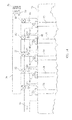
- FIG. 1 is an exploded, schematic perspective view showing a mattress, a sensor array, a sensor cover, and a series of thermally conductive straps and associated heat flow augmentors.
- FIGS. 2-4 are plan views of the mattress, sensor array and sensor cover of FIG. 1 .
- FIG 5 is an enlarged view of a portion of FIG. 4 showing the thermally conductive straps.
- FIG. 6 is a plan view of the mattress showing the sensor array in relation to the thermally conductive straps and also showing a region of risk on the mattress.
- FIG. 7 is a view similar to that of FIG. 1 showing two regions of risk.
- FIG. 8 is a plan view of a mattress showing a diagonal arrangement of the thermally conductive straps.
- FIG. 9 is a perspective view of a bed showing an arrangement with elongated thermally conductive straps.
- FIG. 10 is an elevation view of the bed of FIG. 9 as seen by an observer viewing the bed in the longitudinal direction.
- FIG. 11 is a view substantially in the direction 11-11 of FIG. 10 .
- FIG 12 is an elevation view showing an heat flow augmentor exemplified by a thermoelectric module and a fan for drawing ambient air past the module.
- FIG. 13 is a schematic plan view of a portion of a mattress having thermally conductive lateral straps, a fan and a duct arrangement for directing ambient air through the ducts.
- FIG. 14 is a view similar to that of FIG. 13 including a chiller for chilling the ambient air
- FIG. 15 is a schematic elevation view showing a multi-layer mattress.
- FIGS. 1-4 show an occupant support comprising a mattress 20 having fluid filled bladders 22 enclosed in a bladder covering 24.
- the mattress has a head end border 26, a foot end border 28 longitudinally spaced from the head end border, a left flank 32 and a right flank 34 laterally spaced from the left flank.
- the bladders typically contain air but could also contain water or other liquid.
- An energy management system includes a series of thermally conductive lateral straps 38 extending laterally across the covering and vertically along the left and right flanks 32, 34 and a series of thermally conductive longitudinal straps 40 extending longitudinally along the covering and vertically along the head and foot borders 26, 28.
- the lateral and longitudinal straps may contact each other at thermally conductive junctures 42 or may be thermally insulated from each other at the locations where they would otherwise intersect and form thermally conductive junctures.
- the term "juncture" and reference numeral 42 are used herein to refer to both an actual, thermally conductive juncture and a nonconductive juxtaposition of the lateral and longitudinal straps.
- the straps define thermally conductive pathways.
- the straps 38, 40 are made of a heat conducting material such as thermally conductive fibers having a thermal conductivity of at least about 4 Watts/meter/degree Kelvin.
- thermally conductive fibers having a thermal conductivity of at least about 4 Watts/meter/degree Kelvin.
- fibers include pitch based carbon fibers and high conductivity polymers.
- the energy management system also includes one or more heat flow augmentors 46 such as thermoelectric module 48.
- a thermoelectric module is a solid state device that converts electrical energy into a thermal gradient. Specifically, when a voltage source 52 applies a voltage to the leads of the thermoelectric module, one side of the thermoelectric module becomes cooler and is referred to as the cold side; the other side of the thermoelectric module becomes warmer and is referred to as the hot side.
- the cold side of a thermoelectric module contacts the left and right termini of each lateral strap and the head and foot termini of each longitudinal strap.
- the hot side of each thermoelectric module communicates with a heat sink, which in FIG. 1 is the ambient air.
- thermoelectric module associated with each strap
- an architecture in which only selected straps are outfitted with a thermoelectric module can be beneficial. To preserve the clarity of FIG. 1 only the connection between the voltage source and one of the thermoelectric modules is shown.
- the occupant support also includes a detector 54 such as pressure sensor array 56 comprising multiple, individual pressure sensors 58 and a controller 60.
- a sensor cover 62 covers the sensor array.
- the quantity of pressure sensors may be equal to or may differ from the number of strap junctures. It is not necessary for the pressure sensors to be vertically juxtaposed over the strap junctures.
- the controller communicates with the sensor array and issues a control command C.
- the detector e.g. the pressure sensor array
- the controller receives information (e.g. pressure data) from the sensor array to determine the location of the region or regions of risk. The determination may rely on the magnitude of the pressure, the rate of change of pressure (dP/dt), the time during which pressure exceeds a threshold or combinations of these and/or other factors.
- pressure derivative could be used by adding air to a region at a known rate and monitoring the local pressure derivative.
- thermoelectric module 48F the thermoelectric module closest to the identified juncture, by commanding the voltage source to apply a voltage across the terminals of module 48F.
- module 48F augments the heat withdrawal through the portion of strap 38B between the juncture 48' and the module 48F.
- Another possible algorithm activates module 48F and its lateral partner module 48V.
- a third possible algorithm activates all four modules 48F, 48V, 48C, and 48M in contact with the straps 40C, 42B that define the juncture.
- a fourth possible algorithm activates all the thermoelectric modules within a specified horizontal distance D of the juncture, i.e. modules 48E, 48F, 48G and 48H.
- FIG. 6 shows distance D as a radius that encompasses all the thermoelectric modules that, when projected onto the plane of the radius, fall within the radius. In other words distance D doesn't account for the vertical distance V ( FIG.
- thermoelectric module 1
- V the distance between the modules.
- a fifth possible algorithm activates a subset of modules whose operation will result in a desired amount of heat withdrawal. Note that "subset" can, in the limit, include all the modules.
- the desired amount of heat withdrawal may or may not be as much as the maximum heat withdrawal capacity of the energy management system.
- the amount of heat transfer augmentation attributable to each thermoelectric module can be controlled by regulating the voltage applied across its terminals.
- FIG 7 shows multiple regions of risk 66A, 66B, each of which corresponds to multiple sensors.
- the control algorithm has selected the strap junctures identified with a plus sign as the junctures corresponding to a region of risk, with the juncture at the juxtaposition of straps 40B and 38D corresponding to both regions 66A and 66B.
- the plus signs superimposed on thermoelectric modules 48H, 481, 48J, 48R, 48S, 48T, 48U and 48V signify that the algorithm has activated those modules to transfer heat away from the two regions of risk.
- FIG. 8 shows an alternate strap configuration in which the straps, designated 70 and 72, extend diagonally rather than laterally and longitudinally.
- FIG. 9 Another alternate configuration, shown in FIG. 9 , takes advantage of the fact that the high thermal conductivity straps will extract some amount of heat from the vicinity of the bed occupant even without operation of the heat extraction modules.
- the configuration of FIG. 9 employs elongated straps that, unlike the straps of FIG. 1 , extend vertically below the mattress. The additional strap surface area exposed to the environment increases heat withdrawal whether or not the thermoelectric modules are activated.
- FIGS. 10 and 11 show another strap arrangement in which lateral straps, rather than extending to the left and right flanks of the mattress, penetrate vertically through the mattress.
- the penetrating arrangement has the advantage that the straps are not exposed at the lateral edges of the mattress where they could be more susceptible to damage or be an annoyance to the bed occupant and visitors or staff near the mattress edge.
- FIG. 12 shows an enhancement in which a fan 74 dedicated to a thermoelectric module directs ambient air over the hot side of the thermoelectric module to further enhance heat transfer.
- FIG. 13 shows an enhancement with a duct arrangement so that a single fan 74' can direct ambient air over the hot side of two or more thermoelectric module to convectively augment the heat withdrawal.
- the duct arrangement includes a trunk 78 and branches 80. Valves 82 under the command of controller 60 admit air at least to the branches leading to activated thermoelectric modules. A common exhaust duct 84 is provided to collect the exhaust air from all the branches.
- FIG. 14 shows an arrangement similar to that of FIG. 13 but which employs a chiller 86 to chill the air directed over the activated thermoelectric modules.
- the sensor array has been described as an array of pressure sensors that rests on the mattress and under a sensor cover. Accordingly, the sensor array detects interface pressure, i.e. pressure at the occupant/cover or cover/sensor interface.
- the sensor array can reside between adjacent layers, e.g. layers L 2 and L 3 , and sense interface pressure at the corresponding inter-layer interface I 2-3 .
- the mattress is one having liquid filled bladders, the sensors could be installed in the interior of the bladders so that the sensors detect intra-bladder pressure rather than an interface pressure.
- pressure sensing is thought to be a useful way to determine regions of risk, sensing other parameters, such as temperature, and/or using alternative sensing technologies might also prove satisfactory for determining regions of risk.
- the mattress 20 has been shown as a bladder type mattress, however the innovations described herein can also be used with other types of mattresses such as foam mattresses.
- thermoelectric modules 48 are envisioned as suitable devices for promoting localized heat withdrawal, however a wide array of other types of heat exchange devices 46 can also be used
Abstract
Description
- The subject matter described herein relates to microclimate management of a bed or other occupant support, and particularly to localized control of a microclimate system comprising high thermal conductivity pathways.
- Hospital beds and other occupant supports include a frame and a mattress or other occupant interface. An occupant confined to the bed for an extended time may develop pressure ulcers, especially at the locations on the occupant's body that exert the most pressure on the occupant interface. The risk of an occupant developing pressure ulcers can be reduced by controlling the microclimate, i.e. parameters such as temperature in the immediate vicinity of the occupant. In particular, the risk of pressure ulcers can be reduced by cooling the susceptible portions of the occupant's body.
- One way to control the microclimate involves the use of a "topper", an envelope of material that rests on the mattress so that the topper, rather than the mattress itself, serves as the occupant interface. The topper has a fluid inlet and a fluid outlet. In operation, a blower forces a fluid, usually ambient air, into the interior of the topper by way of the inlet. The air enters the topper and discharges to the environment through the outlet. The flow of ambient air through the topper helps convect heat away from the parts of the occupant's body in contact with the topper, and thereby reduces the risk of pressure ulcers. Heat convection can be enhanced by using chilled air rather than ambient air.
- Although microclimate management toppers as described above are effective they are not without limitations. The heat withdrawal capacity of the described topper is substantially spatially uniform, i.e. it's potential for extracting heat from those portions of the occupant's body that bear heavily on the occupant interface is the same as its potential for extracting heat from those portions of the occupant's body that bear lightly on the interface (and which therefore don't require as much heat extraction). The uniformity of heat extraction potential even extends to those portions of the topper not in contact with the occupant. In addition, the fact that a large portion of the occupant's body contacts the topper means that the benefits of using chilled air can be offset by the associated risk of hypothermia. Although the risk of hypothermia might be addressed by compartmentalizing the topper and directing air only to selected compartments or zones, such an approach complicates the architecture of the topper and requires ductwork and valves that increase the weight, cost and complexity of the bed and adversely affect bed transportabilty, marketability and reliability.
- What is needed is an occupant support having localizable microclimate management capabilities while avoiding at least some of the disadvantages described above.
- An occupant support includes a mattress, a detector and an energy management system comprising thermally conductive pathways and a controller. The controller activates one or more selected pathways in response to information from the detector to regulate energy transfer at a detected region of risk on the mattress.
- The invention will now be further described by way of example with reference to the accompanying drawings, in which:
-
FIG. 1 is an exploded, schematic perspective view showing a mattress, a sensor array, a sensor cover, and a series of thermally conductive straps and associated heat flow augmentors. -
FIGS. 2-4 are plan views of the mattress, sensor array and sensor cover ofFIG. 1 . -
FIG 5 is an enlarged view of a portion ofFIG. 4 showing the thermally conductive straps. -
FIG. 6 is a plan view of the mattress showing the sensor array in relation to the thermally conductive straps and also showing a region of risk on the mattress. -
FIG. 7 is a view similar to that ofFIG. 1 showing two regions of risk. -
FIG. 8 is a plan view of a mattress showing a diagonal arrangement of the thermally conductive straps. -
FIG. 9 is a perspective view of a bed showing an arrangement with elongated thermally conductive straps. -
FIG. 10 is an elevation view of the bed ofFIG. 9 as seen by an observer viewing the bed in the longitudinal direction. -
FIG. 11 is a view substantially in the direction 11-11 ofFIG. 10 . -
FIG 12 is an elevation view showing an heat flow augmentor exemplified by a thermoelectric module and a fan for drawing ambient air past the module. -
FIG. 13 is a schematic plan view of a portion of a mattress having thermally conductive lateral straps, a fan and a duct arrangement for directing ambient air through the ducts. -
FIG. 14 is a view similar to that ofFIG. 13 including a chiller for chilling the ambient air -
FIG. 15 is a schematic elevation view showing a multi-layer mattress. -
FIGS. 1-4 show an occupant support comprising amattress 20 having fluid filledbladders 22 enclosed in a bladder covering 24. The mattress has ahead end border 26, afoot end border 28 longitudinally spaced from the head end border, aleft flank 32 and aright flank 34 laterally spaced from the left flank. The bladders typically contain air but could also contain water or other liquid. - An energy management system includes a series of thermally conductive
lateral straps 38 extending laterally across the covering and vertically along the left andright flanks longitudinal straps 40 extending longitudinally along the covering and vertically along the head andfoot borders conductive junctures 42 or may be thermally insulated from each other at the locations where they would otherwise intersect and form thermally conductive junctures. The term "juncture" andreference numeral 42 are used herein to refer to both an actual, thermally conductive juncture and a nonconductive juxtaposition of the lateral and longitudinal straps. The straps define thermally conductive pathways. AlthoughFIG. 1 shows the use of both lateral and longitudinal straps it may not be necessary to employ both types. - As indicated most clearly in
FIG. 5 , thestraps - The energy management system also includes one or more
heat flow augmentors 46 such asthermoelectric module 48. A thermoelectric module is a solid state device that converts electrical energy into a thermal gradient. Specifically, when avoltage source 52 applies a voltage to the leads of the thermoelectric module, one side of the thermoelectric module becomes cooler and is referred to as the cold side; the other side of the thermoelectric module becomes warmer and is referred to as the hot side. The cold side of a thermoelectric module contacts the left and right termini of each lateral strap and the head and foot termini of each longitudinal strap. The hot side of each thermoelectric module communicates with a heat sink, which inFIG. 1 is the ambient air. Although the foregoing discussion describes at least one thermoelectric module associated with each strap, it is also contemplated that an architecture in which only selected straps are outfitted with a thermoelectric module can be beneficial. To preserve the clarity ofFIG. 1 only the connection between the voltage source and one of the thermoelectric modules is shown. - The occupant support also includes a
detector 54 such aspressure sensor array 56 comprising multiple,individual pressure sensors 58 and acontroller 60. Asensor cover 62 covers the sensor array. The quantity of pressure sensors may be equal to or may differ from the number of strap junctures. It is not necessary for the pressure sensors to be vertically juxtaposed over the strap junctures. As indicated schematically inFIG. 1 the controller communicates with the sensor array and issues a control command C. - When the mattress is occupied, the patient and the mattress exerts a spatially non-uniform pressure on each other. The locations where the pressure on the mattress is high correspond to the portions of the occupant's body susceptible to pressure ulcers and therefore define a region of risk on the mattress. The detector, e.g. the pressure sensor array, senses the pressure on the mattress. The controller receives information (e.g. pressure data) from the sensor array to determine the location of the region or regions of risk. The determination may rely on the magnitude of the pressure, the rate of change of pressure (dP/dt), the time during which pressure exceeds a threshold or combinations of these and/or other factors. For example pressure derivative could be used by adding air to a region at a known rate and monitoring the local pressure derivative. Heavily loaded regions will show a relatively rapid increase in pressure whereas more lightly loaded regions will show a relatively slower increase in local pressure. Once the location of the high risk region has been determined a control algorithm identifies certain thermoelectric modules as being effective for withdrawing a meaningful quantity of heat from a region or regions of risk and issues a command C to activate those modules.
FIG. 6 shows a simple example in which the region ofrisk 66 corresponds to the location of asingle pressure sensor 58A. One possible algorithm identifies the strap juncture 42' closest to the region of risk and activatesthermoelectric module 48F, the thermoelectric module closest to the identified juncture, by commanding the voltage source to apply a voltage across the terminals ofmodule 48F. Activation ofmodule 48F augments the heat withdrawal through the portion ofstrap 38B between the juncture 48' and themodule 48F. Another possible algorithm activatesmodule 48F and itslateral partner module 48V. A third possible algorithm activates all fourmodules straps 40C, 42B that define the juncture. A fourth possible algorithm activates all the thermoelectric modules within a specified horizontal distance D of the juncture, i.e.modules FIG. 6 shows distance D as a radius that encompasses all the thermoelectric modules that, when projected onto the plane of the radius, fall within the radius. In other words distance D doesn't account for the vertical distance V (FIG. 1 ) from the top of the mattress to the thermoelectric module. However the distance V could be accounted for if desired. A fifth possible algorithm activates a subset of modules whose operation will result in a desired amount of heat withdrawal. Note that "subset" can, in the limit, include all the modules. The desired amount of heat withdrawal may or may not be as much as the maximum heat withdrawal capacity of the energy management system. The amount of heat transfer augmentation attributable to each thermoelectric module can be controlled by regulating the voltage applied across its terminals. -
FIG 7 shows multiple regions ofrisk 66A, 66B, each of which corresponds to multiple sensors. The fact that the borders ofregions 66A and 66B (andregion 66 inFIG. 6 )do not coincide exactly with the locations of theindividual pressure sensors 58 reflects the possibility that the algorithm for determining the boundary of a risk region could extrapolate beyond and/or interpolate between the exact locations of the sensors. The control algorithm has selected the strap junctures identified with a plus sign as the junctures corresponding to a region of risk, with the juncture at the juxtaposition ofstraps regions 66A and 66B. The plus signs superimposed onthermoelectric modules -
FIG. 8 shows an alternate strap configuration in which the straps, designated 70 and 72, extend diagonally rather than laterally and longitudinally. - Another alternate configuration, shown in
FIG. 9 , takes advantage of the fact that the high thermal conductivity straps will extract some amount of heat from the vicinity of the bed occupant even without operation of the heat extraction modules. The configuration ofFIG. 9 employs elongated straps that, unlike the straps ofFIG. 1 , extend vertically below the mattress. The additional strap surface area exposed to the environment increases heat withdrawal whether or not the thermoelectric modules are activated. -
FIGS. 10 and 11 show another strap arrangement in which lateral straps, rather than extending to the left and right flanks of the mattress, penetrate vertically through the mattress. Although similar to the arrangement ofFIG. 9 , the penetrating arrangement has the advantage that the straps are not exposed at the lateral edges of the mattress where they could be more susceptible to damage or be an annoyance to the bed occupant and visitors or staff near the mattress edge. -
FIG. 12 shows an enhancement in which afan 74 dedicated to a thermoelectric module directs ambient air over the hot side of the thermoelectric module to further enhance heat transfer. -
FIG. 13 shows an enhancement with a duct arrangement so that a single fan 74' can direct ambient air over the hot side of two or more thermoelectric module to convectively augment the heat withdrawal. The duct arrangement includes atrunk 78 andbranches 80.Valves 82 under the command ofcontroller 60 admit air at least to the branches leading to activated thermoelectric modules. Acommon exhaust duct 84 is provided to collect the exhaust air from all the branches. -
FIG. 14 shows an arrangement similar to that ofFIG. 13 but which employs achiller 86 to chill the air directed over the activated thermoelectric modules. - With the certain features of the occupant support having now been described, other features and variations can now be better appreciated. The sensor array has been described as an array of pressure sensors that rests on the mattress and under a sensor cover. Accordingly, the sensor array detects interface pressure, i.e. pressure at the occupant/cover or cover/sensor interface. Alternatively, if the mattress is a multi-layer mattress, as seen in
FIG. 15 , the sensor array can reside between adjacent layers, e.g. layers L2 and L3, and sense interface pressure at the corresponding inter-layer interface I2-3. If the mattress is one having liquid filled bladders, the sensors could be installed in the interior of the bladders so that the sensors detect intra-bladder pressure rather than an interface pressure. And although pressure sensing is thought to be a useful way to determine regions of risk, sensing other parameters, such as temperature, and/or using alternative sensing technologies might also prove satisfactory for determining regions of risk. - The
mattress 20 has been shown as a bladder type mattress, however the innovations described herein can also be used with other types of mattresses such as foam mattresses. In addition, althoughthermoelectric modules 48 are envisioned as suitable devices for promoting localized heat withdrawal, however a wide array of other types ofheat exchange devices 46 can also be used - Although this disclosure refers to specific embodiments, it will be understood by those skilled in the art that various changes in form and detail may be made.
- Embodiments of the invention can be described with reference to the following numbered clauses, with preferred features laid out in the dependent clauses:
- 1. An occupant support, comprising a mattress, a detector and an energy management system comprising thermally conductive pathways and a controller for activating a selected pathway in response to information from the detector to regulate energy transfer at a detected region of risk on the mattress.
- 2. The occupant support of clause 1 wherein the energy management system conducts heat away from the region of risk.
- 3. The occupant support of either clause 1 or clause 2 wherein the energy management system includes one or more heat flow augmentors for augmenting heat flow along the pathways.
- 4. The occupant support of any preceding clause wherein the pathways are straps of thermally conductive fibers, preferably having a thermal conductivity of at least 4 watts per meter per degree Kelvin (W/m-K).
- 5. The occupant support of clause 4 wherein the energy management system comprises at least one heat flow augmentor associated with one or more of the straps.
- 6. The occupant support of any preceding clause wherein the thermally conductive pathways include a set of lateral straps and a set of longitudinal straps, the lateral and longitudinal straps defining junctures, the energy management system includes at least one heat flow augmentor associated with at least some of the lateral straps and at least one heat flow augmentor associated with at least some of the longitudinal straps for enhancing heat transfer along the straps, and, the selected pathway is activated by a controller's issuance of a command to operate a subset of the heat flow augmentors.
- 7. The occupant support of clause 18 wherein the controller identifies a juncture closest to the region of risk and commands operation of a single heat flow augmentor closest to the identified juncture, or commands operation of a heat flow augmentor closest to the identified juncture and its lateral or longitudinal partner heat flow augmentor, or commands operation of all heat flow augmentors connected to the lateral and longitudinal straps that define the identified juncture, or commands operation of all heat flow augmentors within a specified distance of the identified juncture, or commands operation of a subset of the heat flow augmentors effective to cause a desired amount of heat withdrawal.
- 8. The occupant support of any one of clauses 5 to 7 wherein the heat flow augmentor is a thermoelectric module.
- 9. The occupant support of clause 8 wherein the thermoelectric module has a hot side and the occupant support includes means for cooling the hot side.
- 10. The occupant support of clause 9 including a chiller for producing chilled coolant and a duct system for directing the chilled coolant past the hot side of one or more thermoelectric modules
- 11. The occupant support of any preceding clause wherein the detector detects pressure for use in determining the region of risk.
- 12. The occupant support of
clause 11 wherein the detected pressure is an interface pressure. - 13. The occupant support of
clause 11 comprising fluid bladders and wherein the detected pressure is an intra-bladder pressure. - 14. The occupant support of
clause 11 wherein an interval of time during which pressure exceeds a threshhold pressure is used to determine the region of risk. - 15. The occupant support of any preceding clause wherein the detector detects temperature for use in determining the region of risk.
Claims (15)
- An occupant support comprising:a mattress,a detector, andan energy management system comprising a plurality of straps defining thermally conductive pathways and a controller for activating a selected pathway in response to information from the detector to regulate energy transfer at a selected region of the mattress, wherein the energy management system includes a plurality of heat flow augmentors which each comprise a solid state device, each solid state device being coupled to an end region of a respective one of the plurality of straps such that the opposite end regions of each of the plurality of straps have a solid state device coupled thereto, the solid state devices being configured so that, when a voltage is applied, thermal energy is transferred at the selected region.
- The occupant support of claim 1, wherein the straps comprise thermally conductive fibers having a thermal conductivity of at least 4 watts per meter per degree Kelvin (W/m-K).
- The occupant support of either claim 1 or claim 2, wherein the solid state devices each comprise a thermoelectric module.
- The occupant support of claim 3, wherein the thermoelectric module has a first side and the occupant support includes a fan for causing air to flow past the first side.
- The occupant support of claim 4, further including one fan for each thermoelectric module.
- The occupant support of claim 4, wherein one fan causes the flow of air past the first side of two or more thermoelectric modules.
- The occupant support of claim 3, wherein the thermoelectric module has a first side and further comprising a chiller for producing chilled coolant and a duct system for directing the chilled coolant past the first side of one or more selected thermoelectric modules.
- The occupant support of any preceding claim, wherein the detector detects pressure for use in determining the selected region.
- The occupant support of claim 8, wherein the detected pressure comprises an interface pressure.
- The occupant support of claim 8, further comprising one or more fluid bladders and wherein the detected pressure comprises an intra-bladder pressure.
- The occupant support of claim 8, wherein a time rate of change of pressure is used to determine the selected region.
- The occupant support of claim 8, wherein an interval of time during which the detected pressure exceeds a threshold pressure is used to determine the selected region.
- The occupant support of any preceding claim, wherein the detector detects temperature for use in determining the selected region.
- The occupant support of any preceding claim, wherein the plurality of straps include a set of lateral straps and a set of longitudinal straps, the lateral and longitudinal straps defining junctures, and the selected pathway is activated by the controller issuing a command to operate a subset of the heat flow augmentors.
- The occupant support of claim 14, wherein the controller identifies a juncture closest to the selected region and commands operation of at least one heat flow augmentor associated with the identified juncture, or commands operation of a heat flow augmentor closest to the identified juncture and its lateral or longitudinal partner heat flow augmentor, or commands operation of all heat flow augmentors connected to the lateral and longitudinal straps that define the identified juncture, or commands operation of all heat flow augmentors within a specified distance of the identified juncture, or commands operation of a subset of the heat flow augmentors effective to cause a desired amount of thermal energy transfer.
Applications Claiming Priority (2)
| Application Number | Priority Date | Filing Date | Title |
|---|---|---|---|
| US12/493,456 US8327477B2 (en) | 2009-06-29 | 2009-06-29 | Localized microclimate management |
| EP10251104A EP2269547A1 (en) | 2009-06-29 | 2010-06-17 | Localized microclimate management |
Related Parent Applications (1)
| Application Number | Title | Priority Date | Filing Date |
|---|---|---|---|
| EP10251104A Division EP2269547A1 (en) | 2009-06-29 | 2010-06-17 | Localized microclimate management |
Publications (2)
| Publication Number | Publication Date |
|---|---|
| EP2689756A1 true EP2689756A1 (en) | 2014-01-29 |
| EP2689756B1 EP2689756B1 (en) | 2015-04-01 |
Family
ID=42711755
Family Applications (2)
| Application Number | Title | Priority Date | Filing Date |
|---|---|---|---|
| EP13190107.6A Not-in-force EP2689756B1 (en) | 2009-06-29 | 2010-06-17 | Localized microclimate management |
| EP10251104A Withdrawn EP2269547A1 (en) | 2009-06-29 | 2010-06-17 | Localized microclimate management |
Family Applications After (1)
| Application Number | Title | Priority Date | Filing Date |
|---|---|---|---|
| EP10251104A Withdrawn EP2269547A1 (en) | 2009-06-29 | 2010-06-17 | Localized microclimate management |
Country Status (3)
| Country | Link |
|---|---|
| US (3) | US8327477B2 (en) |
| EP (2) | EP2689756B1 (en) |
| JP (1) | JP5247763B2 (en) |
Families Citing this family (55)
| Publication number | Priority date | Publication date | Assignee | Title |
|---|---|---|---|---|
| ES2520715T3 (en) | 2006-10-13 | 2014-11-11 | Gentherm Incorporated | Air-conditioned bed |
| US20150366367A1 (en) | 2007-03-19 | 2015-12-24 | Augustine Temperature Management LLC | Electric heating pad with electrosurgical grounding |
| US10201935B2 (en) | 2007-03-19 | 2019-02-12 | Augustine Temperature Management LLC | Electric heating pad |
| US20150289817A1 (en) | 2014-04-10 | 2015-10-15 | Augustine Biomedical And Design, Llc | Medical apparatus including hydrogen peroxide protection |
| US8283602B2 (en) | 2007-03-19 | 2012-10-09 | Augustine Temperature Management LLC | Heating blanket |
| US7877827B2 (en) | 2007-09-10 | 2011-02-01 | Amerigon Incorporated | Operational control schemes for ventilated seat or bed assemblies |
| US9125497B2 (en) | 2007-10-15 | 2015-09-08 | Gentherm Incorporated | Climate controlled bed assembly with intermediate layer |
| US8181290B2 (en) | 2008-07-18 | 2012-05-22 | Amerigon Incorporated | Climate controlled bed assembly |
| WO2010129803A1 (en) | 2009-05-06 | 2010-11-11 | Amerigon, Inc. | Control schemes and features for climate-controlled beds |
| US8327477B2 (en) | 2009-06-29 | 2012-12-11 | Hill-Rom Services, Inc. | Localized microclimate management |
| US8332975B2 (en) | 2009-08-31 | 2012-12-18 | Gentherm Incorporated | Climate-controlled topper member for medical beds |
| US8353069B1 (en) * | 2010-09-07 | 2013-01-15 | Miller Anthony W | Device for heating, cooling and emitting fragrance into bedding on a bed |
| US8969703B2 (en) | 2010-09-13 | 2015-03-03 | Tempronics, Inc. | Distributed thermoelectric string and insulating panel |
| US10010446B2 (en) * | 2011-01-05 | 2018-07-03 | Hill-Rom Services, Inc. | Cooling system for an occupant of an occupant support and a cooling garment |
| US20120191164A1 (en) * | 2011-01-26 | 2012-07-26 | Gander Nicholas M | Radiant heating apparatus and method for therapeutic heating |
| WO2012125916A2 (en) * | 2011-03-16 | 2012-09-20 | Augustine Temperature Management, Llc | Heated under-body warming system |
| BR112013029688A2 (en) * | 2011-05-23 | 2017-01-17 | Koninkl Philips Nv | system and method of microclimate adjustment of bed environments, use of a system and use of heating by means of electrical resistance wires in combination with air flow |
| US9101224B2 (en) | 2011-06-10 | 2015-08-11 | Picard Healthcare Technolgy (Dongguan) Co. Ltd. | Medical air mattress |
| US10143609B2 (en) * | 2011-06-14 | 2018-12-04 | Picard Healthcare Technology (Dongguan) Co. Ltd. | Medical air mattress |
| US20140142462A1 (en) * | 2011-06-15 | 2014-05-22 | Koninklijke Philips N.V. | Peripheral temperature measuring |
| KR20140045408A (en) | 2011-07-06 | 2014-04-16 | 템프로닉스, 인크. | Integration of distributed thermoelectric heating and cooling |
| EP2747719B1 (en) * | 2011-11-21 | 2020-03-25 | Koninklijke Philips N.V. | A system and a computer program for improving a person's sleep |
| US9131780B2 (en) * | 2012-02-14 | 2015-09-15 | Hill-Rom Services, Inc. | Topper with preferential fluid flow distribution |
| US20130212808A1 (en) * | 2012-02-21 | 2013-08-22 | Charles A. Lachenbruch | Topper with Targeted Fluid Flow Distribution |
| WO2013159074A2 (en) * | 2012-04-20 | 2013-10-24 | Life Support Technologies, Inc. | Methods and systems for monitoring a patient to reduce the incidence of pressure ulcers |
| US9638442B2 (en) * | 2012-08-07 | 2017-05-02 | Tempronics, Inc. | Medical, topper, pet wireless, and automated manufacturing of distributed thermoelectric heating and cooling |
| US9572433B2 (en) | 2012-08-15 | 2017-02-21 | Hill-Rom Services, Inc. | Systems and methods for directing fluid flow in a mattress |
| CN104736387B (en) | 2012-09-25 | 2018-01-02 | 佛吉亚汽车座椅有限责任公司 | Seat with thermal |
| US20150208815A1 (en) * | 2012-10-18 | 2015-07-30 | Tempur-Pedic Management, Llc | Support cushions including reticulated materials and methods for controlling surface temperature of same |
| US9326616B2 (en) | 2013-01-10 | 2016-05-03 | Dreamwell, Ltd. | Active airflow temperature controlled bedding systems |
| US9463124B2 (en) | 2013-01-15 | 2016-10-11 | Hill-Rom Services, Inc. | Microclimate system for a patient support apparatus |
| US9333136B2 (en) | 2013-02-28 | 2016-05-10 | Hill-Rom Services, Inc. | Sensors in a mattress cover |
| US20140316495A1 (en) | 2013-04-17 | 2014-10-23 | Augustine Biomedical And Design, Llc | Conformable heated mattress |
| WO2015066518A1 (en) | 2013-11-04 | 2015-05-07 | Tempronics, Inc. | Design of thermoelectric string, panel, and covers for function and durability |
| CN106102520B (en) * | 2014-01-13 | 2019-04-09 | 百德盖尔有限责任公司 | Environment bed with heat recovery system |
| US20170202362A1 (en) * | 2014-04-10 | 2017-07-20 | Neven Sleep, Llc | Ventilating sleep system |
| US9711029B2 (en) | 2014-10-31 | 2017-07-18 | Hill-Rom Services, Inc. | Equipment, dressing and garment wireless connectivity to a patient bed |
| US10206248B2 (en) | 2014-11-13 | 2019-02-12 | Augustine Temperature Management LLC | Heated underbody warming systems with electrosurgical grounding |
| US9913770B2 (en) * | 2015-02-17 | 2018-03-13 | Hill-Rom Services, Inc. | Climate management topper with shape change actuators for regulating coolant distribution |
| US11559421B2 (en) | 2015-06-25 | 2023-01-24 | Hill-Rom Services, Inc. | Protective dressing with reusable phase-change material cooling insert |
| US10765577B2 (en) | 2015-06-30 | 2020-09-08 | Hill-Rom Services, Inc. | Microclimate system for a patient support apparatus |
| EP3167765B1 (en) | 2015-11-13 | 2023-08-23 | Hill-Rom Services, Inc. | Person support systems with cooling features |
| CN106263798B (en) * | 2016-08-30 | 2018-09-18 | 浙江和也健康科技有限公司 | A kind of intelligence magnetic mattress |
| CN106263799B (en) * | 2016-08-30 | 2018-10-09 | 浙江和也健康科技有限公司 | A kind of intelligence health-care mattress |
| CN106419284B (en) * | 2016-08-31 | 2019-03-08 | 深圳市路福寝具有限公司 | A kind of Intelligent temperature-control mattress and its control method |
| US10827846B2 (en) | 2016-10-28 | 2020-11-10 | Sleep Number Corporation | Bed with foot warming system |
| US10966889B2 (en) | 2016-12-29 | 2021-04-06 | Hill-Rom Services, Inc. | Support apparatuses comprising cooling elements |
| US10842288B2 (en) | 2017-01-31 | 2020-11-24 | Hill-Rom Services, Inc. | Person support systems with cooling features |
| EP3479808A1 (en) * | 2017-10-26 | 2019-05-08 | Hill-Rom Services, Inc. | Underbody warming system with focal cooling |
| US11583437B2 (en) | 2018-02-06 | 2023-02-21 | Aspen Surgical Products, Inc. | Reusable warming blanket with phase change material |
| WO2019226968A1 (en) * | 2018-05-25 | 2019-11-28 | Magna Seating Inc. | Vehicle seat with cooling and heating using a flexible thermoelectric device |
| LU100834B1 (en) * | 2018-06-12 | 2019-12-12 | Variowell Dev Gmbh | A padding having hollow volumes and a flexible band |
| US10765580B1 (en) | 2019-03-27 | 2020-09-08 | Augustine Biomedical And Design, Llc | Patient securement system for the surgical trendelenburg position |
| CN115361889A (en) | 2020-04-06 | 2022-11-18 | 紫色创新有限责任公司 | Ventilation mattress |
| US11844733B1 (en) | 2022-06-23 | 2023-12-19 | Augustine Biomedical And Design, Llc | Patient securement system for the surgical Trendelenburg position |
Citations (6)
| Publication number | Priority date | Publication date | Assignee | Title |
|---|---|---|---|---|
| US3888259A (en) * | 1973-08-21 | 1975-06-10 | Robert C Miley | Hypothermia system |
| EP0862901A1 (en) * | 1997-03-05 | 1998-09-09 | Ohmeda Inc. | Thermoelectric infant mattress |
| US6033432A (en) * | 1996-08-30 | 2000-03-07 | Augustine Medical, Inc. | Support apparatus with a plurality of thermal zones providing localized cooling |
| US20050288749A1 (en) * | 2004-06-08 | 2005-12-29 | Lachenbruch Charles A | Heat wick for skin cooling |
| WO2006023479A2 (en) * | 2004-08-16 | 2006-03-02 | Hill-Rom Services, Inc. | Dynamic cellular person support surface |
| EP1779824A2 (en) * | 2001-09-11 | 2007-05-02 | Hill-Rom Services, Inc. | Thermo-regulating patient support structure |
Family Cites Families (7)
| Publication number | Priority date | Publication date | Assignee | Title |
|---|---|---|---|---|
| US3738702A (en) * | 1972-03-15 | 1973-06-12 | Gen Motors Corp | Means for cooling and heating a seat structure |
| US20070272673A1 (en) * | 2001-08-29 | 2007-11-29 | Keane Barry P | Electric mattress and mattress pad |
| US6772825B2 (en) * | 2002-11-04 | 2004-08-10 | Charles A. Lachenbruch | Heat exchange support surface |
| SE0300280L (en) * | 2003-02-04 | 2004-08-05 | Hilding Anders Internat Ab | Apparatus and method for regulating the physical properties of a bed |
| DE602004027485D1 (en) * | 2003-06-13 | 2010-07-15 | Summerville S C | SELF-SUPPORTING SKIN-COOLING SUPPLEMENTS |
| US8745788B2 (en) | 2005-07-26 | 2014-06-10 | Hill-Rom Services. Inc. | System and method for controlling an air mattress |
| US8327477B2 (en) | 2009-06-29 | 2012-12-11 | Hill-Rom Services, Inc. | Localized microclimate management |
-
2009
- 2009-06-29 US US12/493,456 patent/US8327477B2/en active Active
-
2010
- 2010-06-11 JP JP2010133903A patent/JP5247763B2/en not_active Expired - Fee Related
- 2010-06-17 EP EP13190107.6A patent/EP2689756B1/en not_active Not-in-force
- 2010-06-17 EP EP10251104A patent/EP2269547A1/en not_active Withdrawn
-
2012
- 2012-11-29 US US13/688,670 patent/US8578527B2/en not_active Expired - Fee Related
-
2013
- 2013-10-09 US US14/049,273 patent/US8800078B2/en not_active Expired - Fee Related
Patent Citations (6)
| Publication number | Priority date | Publication date | Assignee | Title |
|---|---|---|---|---|
| US3888259A (en) * | 1973-08-21 | 1975-06-10 | Robert C Miley | Hypothermia system |
| US6033432A (en) * | 1996-08-30 | 2000-03-07 | Augustine Medical, Inc. | Support apparatus with a plurality of thermal zones providing localized cooling |
| EP0862901A1 (en) * | 1997-03-05 | 1998-09-09 | Ohmeda Inc. | Thermoelectric infant mattress |
| EP1779824A2 (en) * | 2001-09-11 | 2007-05-02 | Hill-Rom Services, Inc. | Thermo-regulating patient support structure |
| US20050288749A1 (en) * | 2004-06-08 | 2005-12-29 | Lachenbruch Charles A | Heat wick for skin cooling |
| WO2006023479A2 (en) * | 2004-08-16 | 2006-03-02 | Hill-Rom Services, Inc. | Dynamic cellular person support surface |
Also Published As
| Publication number | Publication date |
|---|---|
| US8800078B2 (en) | 2014-08-12 |
| JP2011005249A (en) | 2011-01-13 |
| US20140041118A1 (en) | 2014-02-13 |
| US8578527B2 (en) | 2013-11-12 |
| US8327477B2 (en) | 2012-12-11 |
| EP2269547A1 (en) | 2011-01-05 |
| US20130086745A1 (en) | 2013-04-11 |
| US20100325796A1 (en) | 2010-12-30 |
| EP2689756B1 (en) | 2015-04-01 |
| JP5247763B2 (en) | 2013-07-24 |
Similar Documents
| Publication | Publication Date | Title |
|---|---|---|
| EP2689756B1 (en) | Localized microclimate management | |
| JP6182153B2 (en) | System and method for improving human sleep | |
| US11583096B1 (en) | Multi-zone temperature modulation system for bed or blanket | |
| AU754200B2 (en) | Cooled bedding, cooled cushion, cooled mat, cooled chair, cooled clothes and cooled shoes | |
| US4884304A (en) | Bedding system with selective heating and cooling | |
| US9119479B2 (en) | Adjustable-firmness body support and method | |
| MXPA97006560A (en) | Support device with a plurality of thermal zones that provide local cooling | |
| EP3167765B1 (en) | Person support systems with cooling features | |
| KR20060124553A (en) | Temperature control mat | |
| EP3116349B1 (en) | Pressure variable thermal adaptive microclimate surface and thermoelectric cells for microclimate surface | |
| CN102802567A (en) | Temperature control apparatus and method for thermoregulation of a human body | |
| US20190125578A1 (en) | Underbody warming system with focal cooling | |
| NL1010728C2 (en) | Fluid filled mattress. | |
| KR102037755B1 (en) | Heat mat with multi-layered air cell structure | |
| US20200253387A1 (en) | Method for optimizing skin cooling level of an occupant support surface | |
| KR102187919B1 (en) | Cool or hot water combination type mat | |
| CN219323305U (en) | Temperature control device, intelligent mattress and intelligent bed | |
| EP3262989A1 (en) | Airflow control for head support | |
| KR200320965Y1 (en) | Heating stone bed using circulating heated water separately | |
| KR20210049749A (en) | A Temperature Regulating Mat for a Pet | |
| CN109770617A (en) | A kind of diversity type Natural Circulation hot-water warming mattress | |
| KR20200098966A (en) | A Temperature Regulating Mat for a Pet | |
| ITMI970464U1 (en) | DEVICE FOR THE THERMAL CONDITIONING OF OBJECTS LIKELY TO BE CONTACTED BY THE HUMAN BODY ESPECIALLY FOR BEDS OR SIMILAR | |
| ITMI961089A1 (en) | DEVICE FOR THE THERMAL CONDITIONING OF OBJECTS SUBJECT TO BE CONTACTED BY THE HUMAN BODY, ESPECIALLY FOR BEDS OR |
Legal Events
| Date | Code | Title | Description |
|---|---|---|---|
| PUAI | Public reference made under article 153(3) epc to a published international application that has entered the european phase |
Free format text: ORIGINAL CODE: 0009012 |
|
| AC | Divisional application: reference to earlier application |
Ref document number: 2269547 Country of ref document: EP Kind code of ref document: P |
|
| AK | Designated contracting states |
Kind code of ref document: A1 Designated state(s): AL AT BE BG CH CY CZ DE DK EE ES FI FR GB GR HR HU IE IS IT LI LT LU LV MC MK MT NL NO PL PT RO SE SI SK SM TR |
|
| AX | Request for extension of the european patent |
Extension state: BA ME RS |
|
| 17P | Request for examination filed |
Effective date: 20140729 |
|
| RBV | Designated contracting states (corrected) |
Designated state(s): AL AT BE BG CH CY CZ DE DK EE ES FI FR GB GR HR HU IE IS IT LI LT LU LV MC MK MT NL NO PL PT RO SE SI SK SM TR |
|
| GRAP | Despatch of communication of intention to grant a patent |
Free format text: ORIGINAL CODE: EPIDOSNIGR1 |
|
| INTG | Intention to grant announced |
Effective date: 20141007 |
|
| RIN1 | Information on inventor provided before grant (corrected) |
Inventor name: LACHENBRUCH, CHARLES A Inventor name: RECEVEUR, TIMOTHY JOSEPH |
|
| GRAS | Grant fee paid |
Free format text: ORIGINAL CODE: EPIDOSNIGR3 |
|
| GRAA | (expected) grant |
Free format text: ORIGINAL CODE: 0009210 |
|
| AC | Divisional application: reference to earlier application |
Ref document number: 2269547 Country of ref document: EP Kind code of ref document: P |
|
| AK | Designated contracting states |
Kind code of ref document: B1 Designated state(s): AL AT BE BG CH CY CZ DE DK EE ES FI FR GB GR HR HU IE IS IT LI LT LU LV MC MK MT NL NO PL PT RO SE SI SK SM TR |
|
| REG | Reference to a national code |
Ref country code: GB Ref legal event code: FG4D |
|
| REG | Reference to a national code |
Ref country code: CH Ref legal event code: EP |
|
| REG | Reference to a national code |
Ref country code: IE Ref legal event code: FG4D |
|
| REG | Reference to a national code |
Ref country code: DE Ref legal event code: R096 Ref document number: 602010023692 Country of ref document: DE Effective date: 20150513 |
|
| REG | Reference to a national code |
Ref country code: AT Ref legal event code: REF Ref document number: 718643 Country of ref document: AT Kind code of ref document: T Effective date: 20150515 |
|
| REG | Reference to a national code |
Ref country code: NL Ref legal event code: VDEP Effective date: 20150401 |
|
| REG | Reference to a national code |
Ref country code: AT Ref legal event code: MK05 Ref document number: 718643 Country of ref document: AT Kind code of ref document: T Effective date: 20150401 |
|
| REG | Reference to a national code |
Ref country code: LT Ref legal event code: MG4D |
|
| PG25 | Lapsed in a contracting state [announced via postgrant information from national office to epo] |
Ref country code: NL Free format text: LAPSE BECAUSE OF FAILURE TO SUBMIT A TRANSLATION OF THE DESCRIPTION OR TO PAY THE FEE WITHIN THE PRESCRIBED TIME-LIMIT Effective date: 20150401 |
|
| PG25 | Lapsed in a contracting state [announced via postgrant information from national office to epo] |
Ref country code: PT Free format text: LAPSE BECAUSE OF FAILURE TO SUBMIT A TRANSLATION OF THE DESCRIPTION OR TO PAY THE FEE WITHIN THE PRESCRIBED TIME-LIMIT Effective date: 20150803 Ref country code: CZ Free format text: LAPSE BECAUSE OF FAILURE TO SUBMIT A TRANSLATION OF THE DESCRIPTION OR TO PAY THE FEE WITHIN THE PRESCRIBED TIME-LIMIT Effective date: 20150401 Ref country code: ES Free format text: LAPSE BECAUSE OF FAILURE TO SUBMIT A TRANSLATION OF THE DESCRIPTION OR TO PAY THE FEE WITHIN THE PRESCRIBED TIME-LIMIT Effective date: 20150401 Ref country code: FI Free format text: LAPSE BECAUSE OF FAILURE TO SUBMIT A TRANSLATION OF THE DESCRIPTION OR TO PAY THE FEE WITHIN THE PRESCRIBED TIME-LIMIT Effective date: 20150401 Ref country code: HR Free format text: LAPSE BECAUSE OF FAILURE TO SUBMIT A TRANSLATION OF THE DESCRIPTION OR TO PAY THE FEE WITHIN THE PRESCRIBED TIME-LIMIT Effective date: 20150401 Ref country code: LT Free format text: LAPSE BECAUSE OF FAILURE TO SUBMIT A TRANSLATION OF THE DESCRIPTION OR TO PAY THE FEE WITHIN THE PRESCRIBED TIME-LIMIT Effective date: 20150401 Ref country code: NO Free format text: LAPSE BECAUSE OF FAILURE TO SUBMIT A TRANSLATION OF THE DESCRIPTION OR TO PAY THE FEE WITHIN THE PRESCRIBED TIME-LIMIT Effective date: 20150701 |
|
| PG25 | Lapsed in a contracting state [announced via postgrant information from national office to epo] |
Ref country code: IS Free format text: LAPSE BECAUSE OF FAILURE TO SUBMIT A TRANSLATION OF THE DESCRIPTION OR TO PAY THE FEE WITHIN THE PRESCRIBED TIME-LIMIT Effective date: 20150801 Ref country code: LV Free format text: LAPSE BECAUSE OF FAILURE TO SUBMIT A TRANSLATION OF THE DESCRIPTION OR TO PAY THE FEE WITHIN THE PRESCRIBED TIME-LIMIT Effective date: 20150401 Ref country code: GR Free format text: LAPSE BECAUSE OF FAILURE TO SUBMIT A TRANSLATION OF THE DESCRIPTION OR TO PAY THE FEE WITHIN THE PRESCRIBED TIME-LIMIT Effective date: 20150702 Ref country code: AT Free format text: LAPSE BECAUSE OF FAILURE TO SUBMIT A TRANSLATION OF THE DESCRIPTION OR TO PAY THE FEE WITHIN THE PRESCRIBED TIME-LIMIT Effective date: 20150401 |
|
| REG | Reference to a national code |
Ref country code: DE Ref legal event code: R097 Ref document number: 602010023692 Country of ref document: DE |
|
| PG25 | Lapsed in a contracting state [announced via postgrant information from national office to epo] |
Ref country code: MC Free format text: LAPSE BECAUSE OF FAILURE TO SUBMIT A TRANSLATION OF THE DESCRIPTION OR TO PAY THE FEE WITHIN THE PRESCRIBED TIME-LIMIT Effective date: 20150401 Ref country code: EE Free format text: LAPSE BECAUSE OF FAILURE TO SUBMIT A TRANSLATION OF THE DESCRIPTION OR TO PAY THE FEE WITHIN THE PRESCRIBED TIME-LIMIT Effective date: 20150401 Ref country code: DK Free format text: LAPSE BECAUSE OF FAILURE TO SUBMIT A TRANSLATION OF THE DESCRIPTION OR TO PAY THE FEE WITHIN THE PRESCRIBED TIME-LIMIT Effective date: 20150401 Ref country code: IT Free format text: LAPSE BECAUSE OF FAILURE TO SUBMIT A TRANSLATION OF THE DESCRIPTION OR TO PAY THE FEE WITHIN THE PRESCRIBED TIME-LIMIT Effective date: 20150401 |
|
| REG | Reference to a national code |
Ref country code: CH Ref legal event code: PL |
|
| PLBE | No opposition filed within time limit |
Free format text: ORIGINAL CODE: 0009261 |
|
| STAA | Information on the status of an ep patent application or granted ep patent |
Free format text: STATUS: NO OPPOSITION FILED WITHIN TIME LIMIT |
|
| PG25 | Lapsed in a contracting state [announced via postgrant information from national office to epo] |
Ref country code: SK Free format text: LAPSE BECAUSE OF FAILURE TO SUBMIT A TRANSLATION OF THE DESCRIPTION OR TO PAY THE FEE WITHIN THE PRESCRIBED TIME-LIMIT Effective date: 20150401 Ref country code: RO Free format text: LAPSE BECAUSE OF NON-PAYMENT OF DUE FEES Effective date: 20150401 Ref country code: LU Free format text: LAPSE BECAUSE OF FAILURE TO SUBMIT A TRANSLATION OF THE DESCRIPTION OR TO PAY THE FEE WITHIN THE PRESCRIBED TIME-LIMIT Effective date: 20150617 Ref country code: PL Free format text: LAPSE BECAUSE OF FAILURE TO SUBMIT A TRANSLATION OF THE DESCRIPTION OR TO PAY THE FEE WITHIN THE PRESCRIBED TIME-LIMIT Effective date: 20150401 |
|
| 26N | No opposition filed |
Effective date: 20160105 |
|
| REG | Reference to a national code |
Ref country code: IE Ref legal event code: MM4A |
|
| PG25 | Lapsed in a contracting state [announced via postgrant information from national office to epo] |
Ref country code: IE Free format text: LAPSE BECAUSE OF NON-PAYMENT OF DUE FEES Effective date: 20150617 Ref country code: LI Free format text: LAPSE BECAUSE OF NON-PAYMENT OF DUE FEES Effective date: 20150630 Ref country code: CH Free format text: LAPSE BECAUSE OF NON-PAYMENT OF DUE FEES Effective date: 20150630 |
|
| REG | Reference to a national code |
Ref country code: FR Ref legal event code: PLFP Year of fee payment: 7 |
|
| PG25 | Lapsed in a contracting state [announced via postgrant information from national office to epo] |
Ref country code: SI Free format text: LAPSE BECAUSE OF FAILURE TO SUBMIT A TRANSLATION OF THE DESCRIPTION OR TO PAY THE FEE WITHIN THE PRESCRIBED TIME-LIMIT Effective date: 20150401 |
|
| PG25 | Lapsed in a contracting state [announced via postgrant information from national office to epo] |
Ref country code: BE Free format text: LAPSE BECAUSE OF FAILURE TO SUBMIT A TRANSLATION OF THE DESCRIPTION OR TO PAY THE FEE WITHIN THE PRESCRIBED TIME-LIMIT Effective date: 20150401 |
|
| PG25 | Lapsed in a contracting state [announced via postgrant information from national office to epo] |
Ref country code: MT Free format text: LAPSE BECAUSE OF FAILURE TO SUBMIT A TRANSLATION OF THE DESCRIPTION OR TO PAY THE FEE WITHIN THE PRESCRIBED TIME-LIMIT Effective date: 20150401 |
|
| REG | Reference to a national code |
Ref country code: FR Ref legal event code: PLFP Year of fee payment: 8 |
|
| PG25 | Lapsed in a contracting state [announced via postgrant information from national office to epo] |
Ref country code: HU Free format text: LAPSE BECAUSE OF FAILURE TO SUBMIT A TRANSLATION OF THE DESCRIPTION OR TO PAY THE FEE WITHIN THE PRESCRIBED TIME-LIMIT; INVALID AB INITIO Effective date: 20100617 Ref country code: SM Free format text: LAPSE BECAUSE OF FAILURE TO SUBMIT A TRANSLATION OF THE DESCRIPTION OR TO PAY THE FEE WITHIN THE PRESCRIBED TIME-LIMIT Effective date: 20150401 Ref country code: BG Free format text: LAPSE BECAUSE OF FAILURE TO SUBMIT A TRANSLATION OF THE DESCRIPTION OR TO PAY THE FEE WITHIN THE PRESCRIBED TIME-LIMIT Effective date: 20150401 |
|
| PG25 | Lapsed in a contracting state [announced via postgrant information from national office to epo] |
Ref country code: SE Free format text: LAPSE BECAUSE OF FAILURE TO SUBMIT A TRANSLATION OF THE DESCRIPTION OR TO PAY THE FEE WITHIN THE PRESCRIBED TIME-LIMIT Effective date: 20150401 Ref country code: CY Free format text: LAPSE BECAUSE OF FAILURE TO SUBMIT A TRANSLATION OF THE DESCRIPTION OR TO PAY THE FEE WITHIN THE PRESCRIBED TIME-LIMIT Effective date: 20150401 |
|
| PGFP | Annual fee paid to national office [announced via postgrant information from national office to epo] |
Ref country code: GB Payment date: 20170526 Year of fee payment: 8 Ref country code: FR Payment date: 20170523 Year of fee payment: 8 Ref country code: DE Payment date: 20170522 Year of fee payment: 8 |
|
| PG25 | Lapsed in a contracting state [announced via postgrant information from national office to epo] |
Ref country code: TR Free format text: LAPSE BECAUSE OF FAILURE TO SUBMIT A TRANSLATION OF THE DESCRIPTION OR TO PAY THE FEE WITHIN THE PRESCRIBED TIME-LIMIT Effective date: 20150401 |
|
| PG25 | Lapsed in a contracting state [announced via postgrant information from national office to epo] |
Ref country code: MK Free format text: LAPSE BECAUSE OF FAILURE TO SUBMIT A TRANSLATION OF THE DESCRIPTION OR TO PAY THE FEE WITHIN THE PRESCRIBED TIME-LIMIT Effective date: 20150401 |
|
| PG25 | Lapsed in a contracting state [announced via postgrant information from national office to epo] |
Ref country code: AL Free format text: LAPSE BECAUSE OF FAILURE TO SUBMIT A TRANSLATION OF THE DESCRIPTION OR TO PAY THE FEE WITHIN THE PRESCRIBED TIME-LIMIT Effective date: 20150401 |
|
| REG | Reference to a national code |
Ref country code: DE Ref legal event code: R119 Ref document number: 602010023692 Country of ref document: DE |
|
| GBPC | Gb: european patent ceased through non-payment of renewal fee |
Effective date: 20180617 |
|
| PG25 | Lapsed in a contracting state [announced via postgrant information from national office to epo] |
Ref country code: FR Free format text: LAPSE BECAUSE OF NON-PAYMENT OF DUE FEES Effective date: 20180630 Ref country code: DE Free format text: LAPSE BECAUSE OF NON-PAYMENT OF DUE FEES Effective date: 20190101 Ref country code: GB Free format text: LAPSE BECAUSE OF NON-PAYMENT OF DUE FEES Effective date: 20180617 |