EP2689710A1 - Method for producing optical fiber, optical fiber, and endoscope - Google Patents
Method for producing optical fiber, optical fiber, and endoscope Download PDFInfo
- Publication number
- EP2689710A1 EP2689710A1 EP12859162.5A EP12859162A EP2689710A1 EP 2689710 A1 EP2689710 A1 EP 2689710A1 EP 12859162 A EP12859162 A EP 12859162A EP 2689710 A1 EP2689710 A1 EP 2689710A1
- Authority
- EP
- European Patent Office
- Prior art keywords
- glass
- optical fiber
- core
- clad
- viscosity
- Prior art date
- Legal status (The legal status is an assumption and is not a legal conclusion. Google has not performed a legal analysis and makes no representation as to the accuracy of the status listed.)
- Granted
Links
Images



Classifications
-
- A—HUMAN NECESSITIES
- A61—MEDICAL OR VETERINARY SCIENCE; HYGIENE
- A61B—DIAGNOSIS; SURGERY; IDENTIFICATION
- A61B1/00—Instruments for performing medical examinations of the interior of cavities or tubes of the body by visual or photographical inspection, e.g. endoscopes; Illuminating arrangements therefor
- A61B1/00064—Constructional details of the endoscope body
- A61B1/0011—Manufacturing of endoscope parts
-
- A—HUMAN NECESSITIES
- A61—MEDICAL OR VETERINARY SCIENCE; HYGIENE
- A61B—DIAGNOSIS; SURGERY; IDENTIFICATION
- A61B1/00—Instruments for performing medical examinations of the interior of cavities or tubes of the body by visual or photographical inspection, e.g. endoscopes; Illuminating arrangements therefor
-
- A—HUMAN NECESSITIES
- A61—MEDICAL OR VETERINARY SCIENCE; HYGIENE
- A61B—DIAGNOSIS; SURGERY; IDENTIFICATION
- A61B1/00—Instruments for performing medical examinations of the interior of cavities or tubes of the body by visual or photographical inspection, e.g. endoscopes; Illuminating arrangements therefor
- A61B1/00163—Optical arrangements
- A61B1/00165—Optical arrangements with light-conductive means, e.g. fibre optics
- A61B1/0017—Details of single optical fibres, e.g. material or cladding
-
- A—HUMAN NECESSITIES
- A61—MEDICAL OR VETERINARY SCIENCE; HYGIENE
- A61B—DIAGNOSIS; SURGERY; IDENTIFICATION
- A61B1/00—Instruments for performing medical examinations of the interior of cavities or tubes of the body by visual or photographical inspection, e.g. endoscopes; Illuminating arrangements therefor
- A61B1/06—Instruments for performing medical examinations of the interior of cavities or tubes of the body by visual or photographical inspection, e.g. endoscopes; Illuminating arrangements therefor with illuminating arrangements
- A61B1/07—Instruments for performing medical examinations of the interior of cavities or tubes of the body by visual or photographical inspection, e.g. endoscopes; Illuminating arrangements therefor with illuminating arrangements using light-conductive means, e.g. optical fibres
-
- C—CHEMISTRY; METALLURGY
- C03—GLASS; MINERAL OR SLAG WOOL
- C03B—MANUFACTURE, SHAPING, OR SUPPLEMENTARY PROCESSES
- C03B37/00—Manufacture or treatment of flakes, fibres, or filaments from softened glass, minerals, or slags
- C03B37/01—Manufacture of glass fibres or filaments
- C03B37/02—Manufacture of glass fibres or filaments by drawing or extruding, e.g. direct drawing of molten glass from nozzles; Cooling fins therefor
- C03B37/025—Manufacture of glass fibres or filaments by drawing or extruding, e.g. direct drawing of molten glass from nozzles; Cooling fins therefor from reheated softened tubes, rods, fibres or filaments, e.g. drawing fibres from preforms
- C03B37/027—Fibres composed of different sorts of glass, e.g. glass optical fibres
- C03B37/02718—Thermal treatment of the fibre during the drawing process, e.g. cooling
-
- C—CHEMISTRY; METALLURGY
- C03—GLASS; MINERAL OR SLAG WOOL
- C03B—MANUFACTURE, SHAPING, OR SUPPLEMENTARY PROCESSES
- C03B37/00—Manufacture or treatment of flakes, fibres, or filaments from softened glass, minerals, or slags
- C03B37/01—Manufacture of glass fibres or filaments
- C03B37/02—Manufacture of glass fibres or filaments by drawing or extruding, e.g. direct drawing of molten glass from nozzles; Cooling fins therefor
- C03B37/025—Manufacture of glass fibres or filaments by drawing or extruding, e.g. direct drawing of molten glass from nozzles; Cooling fins therefor from reheated softened tubes, rods, fibres or filaments, e.g. drawing fibres from preforms
- C03B37/027—Fibres composed of different sorts of glass, e.g. glass optical fibres
- C03B37/02754—Solid fibres drawn from hollow preforms
-
- C—CHEMISTRY; METALLURGY
- C03—GLASS; MINERAL OR SLAG WOOL
- C03B—MANUFACTURE, SHAPING, OR SUPPLEMENTARY PROCESSES
- C03B37/00—Manufacture or treatment of flakes, fibres, or filaments from softened glass, minerals, or slags
- C03B37/01—Manufacture of glass fibres or filaments
- C03B37/02—Manufacture of glass fibres or filaments by drawing or extruding, e.g. direct drawing of molten glass from nozzles; Cooling fins therefor
- C03B37/025—Manufacture of glass fibres or filaments by drawing or extruding, e.g. direct drawing of molten glass from nozzles; Cooling fins therefor from reheated softened tubes, rods, fibres or filaments, e.g. drawing fibres from preforms
- C03B37/029—Furnaces therefor
-
- G—PHYSICS
- G02—OPTICS
- G02B—OPTICAL ELEMENTS, SYSTEMS OR APPARATUS
- G02B6/00—Light guides; Structural details of arrangements comprising light guides and other optical elements, e.g. couplings
- G02B6/04—Light guides; Structural details of arrangements comprising light guides and other optical elements, e.g. couplings formed by bundles of fibres
- G02B6/06—Light guides; Structural details of arrangements comprising light guides and other optical elements, e.g. couplings formed by bundles of fibres the relative position of the fibres being the same at both ends, e.g. for transporting images
-
- C—CHEMISTRY; METALLURGY
- C03—GLASS; MINERAL OR SLAG WOOL
- C03B—MANUFACTURE, SHAPING, OR SUPPLEMENTARY PROCESSES
- C03B2201/00—Type of glass produced
- C03B2201/06—Doped silica-based glasses
- C03B2201/08—Doped silica-based glasses doped with boron or fluorine or other refractive index decreasing dopant
- C03B2201/10—Doped silica-based glasses doped with boron or fluorine or other refractive index decreasing dopant doped with boron
-
- C—CHEMISTRY; METALLURGY
- C03—GLASS; MINERAL OR SLAG WOOL
- C03B—MANUFACTURE, SHAPING, OR SUPPLEMENTARY PROCESSES
- C03B2201/00—Type of glass produced
- C03B2201/06—Doped silica-based glasses
- C03B2201/30—Doped silica-based glasses doped with metals, e.g. Ga, Sn, Sb, Pb or Bi
- C03B2201/32—Doped silica-based glasses doped with metals, e.g. Ga, Sn, Sb, Pb or Bi doped with aluminium
-
- C—CHEMISTRY; METALLURGY
- C03—GLASS; MINERAL OR SLAG WOOL
- C03B—MANUFACTURE, SHAPING, OR SUPPLEMENTARY PROCESSES
- C03B2201/00—Type of glass produced
- C03B2201/06—Doped silica-based glasses
- C03B2201/30—Doped silica-based glasses doped with metals, e.g. Ga, Sn, Sb, Pb or Bi
- C03B2201/50—Doped silica-based glasses doped with metals, e.g. Ga, Sn, Sb, Pb or Bi doped with alkali metals
-
- C—CHEMISTRY; METALLURGY
- C03—GLASS; MINERAL OR SLAG WOOL
- C03B—MANUFACTURE, SHAPING, OR SUPPLEMENTARY PROCESSES
- C03B2203/00—Fibre product details, e.g. structure, shape
- C03B2203/10—Internal structure or shape details
- C03B2203/22—Radial profile of refractive index, composition or softening point
- C03B2203/222—Mismatching viscosities or softening points of glass layers
-
- C—CHEMISTRY; METALLURGY
- C03—GLASS; MINERAL OR SLAG WOOL
- C03B—MANUFACTURE, SHAPING, OR SUPPLEMENTARY PROCESSES
- C03B2203/00—Fibre product details, e.g. structure, shape
- C03B2203/32—Eccentric core or cladding
-
- C—CHEMISTRY; METALLURGY
- C03—GLASS; MINERAL OR SLAG WOOL
- C03B—MANUFACTURE, SHAPING, OR SUPPLEMENTARY PROCESSES
- C03B2205/00—Fibre drawing or extruding details
- C03B2205/12—Drawing solid optical fibre directly from a hollow preform
- C03B2205/14—Drawing solid optical fibre directly from a hollow preform comprising collapse of an outer tube onto an inner central solid preform rod
-
- C—CHEMISTRY; METALLURGY
- C03—GLASS; MINERAL OR SLAG WOOL
- C03B—MANUFACTURE, SHAPING, OR SUPPLEMENTARY PROCESSES
- C03B2205/00—Fibre drawing or extruding details
- C03B2205/12—Drawing solid optical fibre directly from a hollow preform
- C03B2205/16—Drawing solid optical fibre directly from a hollow preform the drawn fibre consisting of circularly symmetric core and clad
-
- C—CHEMISTRY; METALLURGY
- C03—GLASS; MINERAL OR SLAG WOOL
- C03B—MANUFACTURE, SHAPING, OR SUPPLEMENTARY PROCESSES
- C03B2205/00—Fibre drawing or extruding details
- C03B2205/60—Optical fibre draw furnaces
- C03B2205/62—Heating means for drawing
- C03B2205/63—Ohmic resistance heaters, e.g. carbon or graphite resistance heaters
-
- G—PHYSICS
- G02—OPTICS
- G02B—OPTICAL ELEMENTS, SYSTEMS OR APPARATUS
- G02B23/00—Telescopes, e.g. binoculars; Periscopes; Instruments for viewing the inside of hollow bodies; Viewfinders; Optical aiming or sighting devices
- G02B23/24—Instruments or systems for viewing the inside of hollow bodies, e.g. fibrescopes
- G02B23/2407—Optical details
- G02B23/2461—Illumination
- G02B23/2469—Illumination using optical fibres
-
- Y—GENERAL TAGGING OF NEW TECHNOLOGICAL DEVELOPMENTS; GENERAL TAGGING OF CROSS-SECTIONAL TECHNOLOGIES SPANNING OVER SEVERAL SECTIONS OF THE IPC; TECHNICAL SUBJECTS COVERED BY FORMER USPC CROSS-REFERENCE ART COLLECTIONS [XRACs] AND DIGESTS
- Y02—TECHNOLOGIES OR APPLICATIONS FOR MITIGATION OR ADAPTATION AGAINST CLIMATE CHANGE
- Y02P—CLIMATE CHANGE MITIGATION TECHNOLOGIES IN THE PRODUCTION OR PROCESSING OF GOODS
- Y02P40/00—Technologies relating to the processing of minerals
- Y02P40/50—Glass production, e.g. reusing waste heat during processing or shaping
- Y02P40/57—Improving the yield, e-g- reduction of reject rates
Definitions
- Embodiments of the present invention relate to a method for manufacturing an optical fiber that is inserted into an insertion portion of an endoscope and guides light, the optical fiber, and an endoscope including the optical fiber.
- a light guide is used to guide light generated by a light source apparatus to an illumination portion disposed in a distal end portion of an insertion portion of the respective endoscopes.
- a light guide has a configuration in which numerous optical fibers are bundled.
- each of the respective optical fibers 10 (with an outer diameter ⁇ F) includes a core 11 (with an outer diameter ⁇ C) that transmits light and a clad 12 that is provided on an outer circumferential portion of the core 11 and reflects light to prevent the light from leaking to the outside from a side face of the core.
- a high-refractive index glass is used, and for the clad 12, a glass with a refractive index that is lower than that of the core 11 is used.
- Japanese Patent Application Laid-Open Publication No. 1-215738 discloses a method for manufacturing an optical fiber for optical communications using a rod-in-tube method.
- melt-spinning what is called “fiber drawing”
- fiber drawing is performed with a rod-like glass, which becomes a core, inserted into a tubular glass, which becomes a clad, in an inner portion of a heating furnace.
- optical fibers for endoscopes and optical fibers for optical communications both have a function that guides light and thus are similar to each other in their basic parts.
- optical fibers for optical communications each convey light with a predetermined narrow range of wavelengths over a long distance of several kilometers or more
- optical fibers for endoscopes need to guide a large amount of light with a broad range of wavelengths, i.e., visible light, although the optical fibers for endoscopes guide such large amount of light over only a short distance of several meters.
- a structure of optical fibers for endoscopes and a method for manufacturing the same are similar in basic part to, but largely different in, e.g., manufacturing conditions from, a structure of optical fibers for optical communications and a method for manufacturing the same.
- the optical fiber for endoscopes has a high proportion of the core diameter ⁇ C to the fiber diameter ⁇ F.
- ⁇ C the core diameter of the core rod
- An object of the present invention is to provide a method for manufacturing an optical fiber for an endoscope with high productivity, an optical fiber of an endoscope with high productivity, and an endoscope including the optical fiber with high productivity.
- An embodiment of the present invention provides a method for manufacturing an optical fiber that is inserted into an insertion portion of an endoscope and guides light, wherein in an inner portion of an upright fiber drawing furnace used in an rod-in-tube method, in an inner portion of a hollow tube including a clad glass, a core glass in a fluidized state runs down by gravity, whereby the core glass and the clad glass are integrated.
- an optical fiber 10 is obtained as a result of a vertically held, elongated core rod 21 including a core glass inserted into a center of a hollow portion of a vertically-held, elongated clad tube 22 including a clad glass being heated and subjected to "fiber drawing" under downward tension in an inner portion of an upright fiber drawing furnace 30.
- a heater 32 and a heat-insulating material 33 are disposed so as to surround a central furnace tube 31, which provides a heating space.
- An inner portion of the furnace tube 31 is designed so that the temperature increases toward the lower side from the upper side.
- Fig. 2 positions Z in the inner portion of the fiber drawing furnace 30 are indicated by values in a Z-axis coordinate in which an upper portion of the fiber drawing furnace 30 is an origin thereof and a Z-axis is an axis with its value increasing toward the lower side (in a gravity direction g).
- Fig. 2 is a schematic diagram for description in which, e.g., shapes and/or sizes of components are different from those of actual ones.
- the core glass (core rod 21) enters a fluidized state at a temperature lower than that of the clad glass (clad tube 22).
- the core rod 21 starts deformation and fluidization at Z1, and enters a fluidized state and vertically runs down by gravity at Z2.
- the core glass (core rod 21) that has run down is integrated with the clad tube 22 at Z2.
- the clad glass (clad tube 22) starts deformation and fluidization at Z3 and a diameter thereof starts decreasing.
- a diameter ⁇ CL of the core glass (core rod 21) that has entered a fluidized state and started running down at Z2 gradually decreases toward the lower side, but the core glass (core rod 21) is received by the clad tube 22 that is not in a fluidized state at Z5 and thus exhibits a minimum value at Z4.
- a diameter of the glass monotonously decreases.
- ⁇ CL decreases from Z1 to Z4, exhibits a minimum value at Z4 and increases from Z4 to Z5.
- ⁇ CL decreases again in a portion below Z5 and finally becomes a core diameter ( ⁇ C) of the fiber 10, for example, 27 ⁇ m.
- the diameter ⁇ CL of the core glass decreases and reaches a minimal value and then increases.
- a drawn optical fiber may have a decentered core position, have a non-circular cross sectional shape and/or have variations in fiber diameter.
- optical fibers for endoscopes have a high ratio ( ⁇ C/ ⁇ F) of a core diameter ⁇ C relative to a fiber diameter ⁇ F in order to guide a large amount of light.
- a core diameter ⁇ C of the optical fiber is no less than 80% of a fiber diameter ⁇ F of the optical fiber.
- the core diameter ⁇ C is preferably no less than 24 ⁇ m (80%), particularly preferably no less than 27 ⁇ m (90%).
- An upper limit of the core diameter ⁇ C is, for example, no more than 95% of the fiber diameter ⁇ F, and a core diameter ⁇ C that is equal to or below the upper limit enables provision of a clad glass thickness necessary for reflection.
- a ratio ( ⁇ CT/ ⁇ CL) of the outer diameter ⁇ CL of the core rod 21 relative to an inner diameter ⁇ CT of the clad tube 22 is high also at the time of manufacture, and a space (gap) between an outer circumferential face of the core rod and an inner circumferential face of the clad tube is small.
- the core rod is easily decentered.
- a fluidized core glass runs down by gravity and is thereby integrated with a clad glass (clad tube 22).
- the diameter of the clad tube 22 further decreases under fiber drawing tension; however, the core glass in the inner portion of the hollow tube (clad tube 22) including the clad glass is in a fluidized state and thus is maintained in a state in which the core glass is evenly charged in the inner portion.
- the fiber drawing tension applied from below the fiber drawing furnace 30 is not strongly applied to an upper portion of the core rod 21, that is, a part of Z > Z1 of the core rod 21 since the core rod 21 is in a fluidized state in Z2 to Z5. Therefore, even if the core rod 21 is somewhat deviated from the center of the clad tube 22 in the upper portion of the fiber drawing furnace 30, no large problem occurs.
- the method for manufacturing the optical fiber 10 according to the present embodiment provides high productivity.
- a core glass (core rod 21) entering a fluidized state at a temperature lower than that of a clad glass (clad tube 22) is a requirement for the method for manufacturing the optical fiber 10 according to the present embodiment.
- a clad glass and a core glass were selected paying attention to change in a viscosity ⁇ 1 ⁇ 1 of the clad glass (clad tube 22) with temperature and change in a viscosity ⁇ 2 of the core glass (core rod 21) with temperature.
- Viscosities ⁇ of the glasses were measured by the following methods.
- a sphere pull-up viscometer is a method in which a viscosity is calculated by assigning a load imposed when a platinum sphere is immersed in melt glass and pulled up at a uniform velocity in the Stokes' law.
- Log is a common logarithm with base 10.
- the clad glass in order to receive the running-down core glass, the clad glass needs to maintain a predetermined hardness (viscosity).
- the position Z5 where the clad glass receives the core glass is lower than the position Z2 where the core glass starts running down, and thus, a temperature at Z5 is higher than a temperature at Z2.
- the viscosity ⁇ 1 of the clad glass is preferably Log ⁇ 1 > 5.0, particularly preferably Log ⁇ 1 > 6.0. Where the viscosity ⁇ 1 exceeds the aforementioned value, the clad glass can stably receive the running-down core glass.
- Fig. 4 indicates changes in viscosity of a core glass A (Core-A), a clad glass A (Clad-A), a clad glass B (Clad-B) and a clad glass C (Clad-C) with temperature.
- the clad glass A (Clad-A) whose viscosity 1 at 880°C is Log ⁇ 1 6.3 meets the above condition.
- a viscosity curve of a clad glass to be combined with the core glass A preferably lies between a viscosity curve of the clad glass B (Clad-B) and a viscosity curve of the clad glass C (Clad-C).
- the core glass includes, for example, borosilicate glass or alumino-borosilicate glass as a main component and has a refractive index nd of 1.56 to 1.73.
- a refractive index nd of the clad glass that includes silica as a main component and also contains, e.g., alkaline components is 1.47 to 1.52.
- the clad glass is selected with estimation of conditions, such as a refractive index, a difference in thermal expansion coefficient between the clad glass and the core glass, wettability between the core glass and the clad glass and difficulty in mutual component diffusion, according to, for example, Appen's equation.
- a viscosity ⁇ of a glass can be adjusted by adjusting contents of alkaline components. In other words, as the contents of the alkaline components increases, the viscosity ⁇ at a same temperature decreases.
- the clad glass A and the clad glass B are the same in main component, but different from each other in contents of alkaline components.
- the clad glass A contains 6 mol% Na and 1.5 mol% K.
- the clad glass B contains 19 mol% Na. Where the effect ofNa imposed on the viscosity is "1'", that of K is "0.85". In other words, an Na equivalent content in the clad glass A is 7 mol%.
- a separately-conducted test indicates that a clad glass meets the viscosity conditions if the clad glass has an alkaline component content of no less than 5 mol % and no more than 17 mol % in Na equivalent.
- the method for manufacturing the optical fiber 10 it is preferable to perform not only temperature management but also time management. In other words, it is preferable to also manage a time period during which a glass, from which a fiber is drawn while the glass moves downward, stays in an region of a predetermined temperature range in the inner portion of the fiber drawing furnace 30.
- the first dwell time is a time period during which the temperature increases from 620°C to 880°C.
- the second dwell time is a time period during which the temperature increases from 910°C to 1010°C.
- Fig. 5 illustrates a temperature distribution in the fiber drawing furnace 30.
- the first dwell time is a dwell time for a first temperature range of 620°C to 880°C
- the second dwell time is a dwell time for a second temperature range of 910°C to 1010°C.
- Each of a dwell time during which the core glass stays in the first temperature range and a dwell time during which the clad glass stays in the second temperature range is more preferably a time period (in minutes) no less than 0.15 times a value of a core outer diameter represented in millimeters for stable manufacture. Note that, although the core outer diameter (core diameter ⁇ CL) varies in the inner portion of the fiber drawing furnace 30, an initial outer diameter of a core glass before fiber drawing processing is used for the dwell time calculation.
- each of the two dwell times is more preferably no less than (30 ⁇ 0.15) minutes, that is, no less than 4.5 minutes.
- the dwell times are each determined based on the fiber drawing speed and the region length. For example, if a length of a temperature region is 20 mm, it is only necessary that the fiber drawing speed in the temperature region be no more than 4 mm/minutes.
- each of the dwell times for the first temperature range and the second temperature range is preferably, for example, a time period (in minutes) no more than twice a value of the core outer diameter represented in millimeters.
- a time period (in minutes) no more than twice a value of the core outer diameter represented in millimeters.
- the core outer diameter is 30 mm
- each of the two dwell times is no more than (30 ⁇ 2) minutes, that is, no more than 60 minutes.
- the core diameter is no less than 80% and no more than 95% of the fiber diameter.
- the optical fiber 10 is manufactured according to a rod-in-tube method using an upright fiber drawing furnace.
- the optical fiber 10 Since the optical fiber 10 provides good productivity, the optical fiber 10 can be manufactured at low costs.
- an endoscope 40 including optical fibers 10 will briefly be described with reference to Fig. 6 .
- An endoscope system 41 including the endoscope 40 includes a CPU 44, which is a processor that processes an image signal, a monitor 45 that displays an endoscopic image, an input section such as a keyboard 46 for a user to set, e.g., use conditions, and a light source apparatus 47.
- a CPU 44 which is a processor that processes an image signal
- a monitor 45 that displays an endoscopic image
- an input section such as a keyboard 46 for a user to set, e.g., use conditions
- a light source apparatus 47 for a user to set, e.g., use conditions
- the endoscope 40 is an electronic endoscope including an insertion portion 48 that includes, in a distal end portion 49 thereof, an image pickup section 50 that picks up a color endoscopic image and an illumination optical system 51, a light guide 42 inserted into an inner portion of the insertion portion 48, the light guide 42 guiding illuminating light from a light source apparatus 47 connected thereto via a light guide connector 52 on the proximal end portion side thereof to the illumination optical system 51, and an electronic connector 53 connecting the image pickup section 50 including, e.g., a CCD and the CPU 44.
- the light guide 42 includes, for example, 2800 optical fibers 10 charged in a silicone tube, each of the optical fibers 10 having a diameter of 30.0 ⁇ m, and has a diameter of 1.8 mm and a length of 1 m.
- the endoscope 40 includes the optical fibers 10, which provide good productivity, and thus, provides good productivity and can be manufactured at low costs.
- the embodiment of the present invention provides effects similar to those of the optical fiber 10 even in the case of an optical fiber for a light guide for image pickup, the light guide guiding light of an object image received by an image pickup optical system in the distal end portion 49 to the proximal end portion side.
- the optical fiber 10 and the method for manufacturing the optical fiber 10 according to the embodiment have various uses for endoscopes.
Landscapes
- Life Sciences & Earth Sciences (AREA)
- Health & Medical Sciences (AREA)
- Engineering & Computer Science (AREA)
- Surgery (AREA)
- Physics & Mathematics (AREA)
- Chemical & Material Sciences (AREA)
- Optics & Photonics (AREA)
- Veterinary Medicine (AREA)
- Animal Behavior & Ethology (AREA)
- Radiology & Medical Imaging (AREA)
- Biophysics (AREA)
- Biomedical Technology (AREA)
- Heart & Thoracic Surgery (AREA)
- Medical Informatics (AREA)
- Manufacturing & Machinery (AREA)
- Nuclear Medicine, Radiotherapy & Molecular Imaging (AREA)
- General Health & Medical Sciences (AREA)
- Pathology (AREA)
- Public Health (AREA)
- Molecular Biology (AREA)
- Geochemistry & Mineralogy (AREA)
- General Life Sciences & Earth Sciences (AREA)
- Materials Engineering (AREA)
- Organic Chemistry (AREA)
- General Physics & Mathematics (AREA)
- Thermal Sciences (AREA)
- Manufacture, Treatment Of Glass Fibers (AREA)
- Endoscopes (AREA)
- Glass Compositions (AREA)
- Instruments For Viewing The Inside Of Hollow Bodies (AREA)
Abstract
Description
- Embodiments of the present invention relate to a method for manufacturing an optical fiber that is inserted into an insertion portion of an endoscope and guides light, the optical fiber, and an endoscope including the optical fiber.
- Medical endoscopes need to illuminate object in order to observe the inside of a dark body cavity. Therefore, a light guide is used to guide light generated by a light source apparatus to an illumination portion disposed in a distal end portion of an insertion portion of the respective endoscopes.
- A light guide has a configuration in which numerous optical fibers are bundled. As illustrated in
Fig. 1 , each of the respective optical fibers 10 (with an outer diameter φF) includes a core 11 (with an outer diameter φC) that transmits light and aclad 12 that is provided on an outer circumferential portion of thecore 11 and reflects light to prevent the light from leaking to the outside from a side face of the core. For thecore 11, a high-refractive index glass is used, and for theclad 12, a glass with a refractive index that is lower than that of thecore 11 is used. - As an example of optical fiber manufacturing methods, Japanese Patent Application Laid-Open Publication No.
1-215738 - Here, optical fibers for endoscopes and optical fibers for optical communications both have a function that guides light and thus are similar to each other in their basic parts. However, while optical fibers for optical communications each convey light with a predetermined narrow range of wavelengths over a long distance of several kilometers or more, optical fibers for endoscopes need to guide a large amount of light with a broad range of wavelengths, i.e., visible light, although the optical fibers for endoscopes guide such large amount of light over only a short distance of several meters. Thus, although a structure of optical fibers for endoscopes and a method for manufacturing the same are similar in basic part to, but largely different in, e.g., manufacturing conditions from, a structure of optical fibers for optical communications and a method for manufacturing the same.
- For example, in comparison with the optical fiber for optical communications, the optical fiber for endoscopes has a high proportion of the core diameter φC to the fiber diameter φF. Thus, it is not easy to perform the fiber drawing in a state where the core rod is accurately arranged at a center of the clad tube and there has been a problem of enhancing productivity.
- An object of the present invention is to provide a method for manufacturing an optical fiber for an endoscope with high productivity, an optical fiber of an endoscope with high productivity, and an endoscope including the optical fiber with high productivity.
- An embodiment of the present invention provides a method for manufacturing an optical fiber that is inserted into an insertion portion of an endoscope and guides light, wherein in an inner portion of an upright fiber drawing furnace used in an rod-in-tube method, in an inner portion of a hollow tube including a clad glass, a core glass in a fluidized state runs down by gravity, whereby the core glass and the clad glass are integrated.
- Another embodiment of the present invention provides an optical fiber that is inserted into an insertion portion of an endoscope and guides light, wherein a viscosity η1 of a clad glass at a temperature at which a viscosity η2 of a core glass becomes Logη2 = 3.5 is 5.0 < Logη1 < 7.0.
- Yet another embodiment of the present invention provides an endoscope including an optical fiber that is inserted into an insertion portion and guides light, wherein a viscosity η1 of a clad glass at a temperature at which a viscosity η2 of a core glass becomes Logη2 = 3.5 is 5.0 < Logη1 < 7.0.
-
-
Fig. 1 is a diagram for describing a structure of an optical fiber; -
Fig. 2 is a schematic cross-sectional diagram for describing a method for manufacturing an optical fiber according to a rod-in-tube method using a fiber drawing furnace according to an embodiment; -
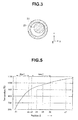
Fig. 3 is a cross-sectional diagram for describing a problem in optical fiber manufacture according to a rod-in-tube method; -
Fig. 4 is a diagram illustrating changes in viscosity of glasses with temperature; -
Fig. 5 is a diagram illustrating a temperature distribution in a fiber drawing furnace according to an embodiment; and -
Fig. 6 is a configuration diagram for describing a configuration of an endoscope according to an embodiment. - As illustrated in
Fig. 2 , anoptical fiber 10 according to an embodiment is obtained as a result of a vertically held,elongated core rod 21 including a core glass inserted into a center of a hollow portion of a vertically-held, elongatedclad tube 22 including a clad glass being heated and subjected to "fiber drawing" under downward tension in an inner portion of an uprightfiber drawing furnace 30. - In the
fiber drawing furnace 30, aheater 32 and a heat-insulatingmaterial 33 are disposed so as to surround acentral furnace tube 31, which provides a heating space. An inner portion of thefurnace tube 31 is designed so that the temperature increases toward the lower side from the upper side. - Hereinafter, as illustrated in
Fig. 2 , positions Z in the inner portion of thefiber drawing furnace 30 are indicated by values in a Z-axis coordinate in which an upper portion of thefiber drawing furnace 30 is an origin thereof and a Z-axis is an axis with its value increasing toward the lower side (in a gravity direction g). Here,Fig. 2 is a schematic diagram for description in which, e.g., shapes and/or sizes of components are different from those of actual ones. - In the
optical fiber 10, the core glass (core rod 21) enters a fluidized state at a temperature lower than that of the clad glass (clad tube 22). Thus, as illustrated inFig. 2 , thecore rod 21 starts deformation and fluidization at Z1, and enters a fluidized state and vertically runs down by gravity at Z2. The core glass (core rod 21) that has run down is integrated with theclad tube 22 at Z2. Note that the clad glass (clad tube 22) starts deformation and fluidization at Z3 and a diameter thereof starts decreasing. - Here, a diameter φCL of the core glass (core rod 21) that has entered a fluidized state and started running down at Z2 gradually decreases toward the lower side, but the core glass (core rod 21) is received by the
clad tube 22 that is not in a fluidized state at Z5 and thus exhibits a minimum value at Z4. In general, where a glass is deformed under fiber drawing tension, a diameter of the glass monotonously decreases. On the other hand, in a method for manufacturing theoptical fiber 10, φCL decreases from Z1 to Z4, exhibits a minimum value at Z4 and increases from Z4 to Z5. Then, φCL decreases again in a portion below Z5 and finally becomes a core diameter (φC) of thefiber 10, for example, 27 µm. In other words, inside the fiber drawingfurnace 30, the diameter φCL of the core glass decreases and reaches a minimal value and then increases. - As already explained, in a method for manufacturing an optical fiber according to a rod-in-tube method, it is not easy to perform fiber drawing with the
core rod 21 accurately arranged in a center of theclad tube 22 inside the fiber drawing furnace. In other words, as illustrated inFig. 3 , slight deviation of thecore rod 21 from the center of theclad tube 22 may result in thecore rod 21 sticking to a part of an inner wall of theclad tube 22 in a phase in which an outer diameter of thecore rod 21 is smaller than an inner diameter of theclad tube 22. Consequently, a drawn optical fiber may have a decentered core position, have a non-circular cross sectional shape and/or have variations in fiber diameter. - In particular, optical fibers for endoscopes have a high ratio (φC/φF) of a core diameter φC relative to a fiber diameter φF in order to guide a large amount of light. For example, an optical fiber cannot guide a desired amount of light unless a core diameter φC of the optical fiber is no less than 80% of a fiber diameter φF of the optical fiber. For example, where the fiber diameter φF is 30 µm, the core diameter φC is preferably no less than 24 µm (80%), particularly preferably no less than 27 µm (90%). An upper limit of the core diameter φC is, for example, no more than 95% of the fiber diameter φF, and a core diameter φC that is equal to or below the upper limit enables provision of a clad glass thickness necessary for reflection.
- Since optical fibers for endoscopes have a high φC/φF ratio as mentioned above, a ratio (φCT/φCL) of the outer diameter φCL of the
core rod 21 relative to an inner diameter φCT of theclad tube 22 is high also at the time of manufacture, and a space (gap) between an outer circumferential face of the core rod and an inner circumferential face of the clad tube is small. Thus, the core rod is easily decentered. - However, in the method for manufacturing an optical fiber according to the present embodiment, a fluidized core glass runs down by gravity and is thereby integrated with a clad glass (clad tube 22). At each of positions below Z4, the diameter of the
clad tube 22 further decreases under fiber drawing tension; however, the core glass in the inner portion of the hollow tube (clad tube 22) including the clad glass is in a fluidized state and thus is maintained in a state in which the core glass is evenly charged in the inner portion. - Also, the fiber drawing tension applied from below the
fiber drawing furnace 30 is not strongly applied to an upper portion of thecore rod 21, that is, a part of Z > Z1 of thecore rod 21 since thecore rod 21 is in a fluidized state in Z2 to Z5. Therefore, even if thecore rod 21 is somewhat deviated from the center of theclad tube 22 in the upper portion of thefiber drawing furnace 30, no large problem occurs. - Thus, the method for manufacturing the
optical fiber 10 according to the present embodiment provides high productivity. - As already described, a core glass (core rod 21) entering a fluidized state at a temperature lower than that of a clad glass (clad tube 22) is a requirement for the method for manufacturing the
optical fiber 10 according to the present embodiment. In other words, a clad glass and a core glass were selected paying attention to change in a viscosity η1 η1 of the clad glass (clad tube 22) with temperature and change in a viscosity η2 of the core glass (core rod 21) with temperature. - Note that the Viscosities η of the glasses were measured by the following methods.
-
- Fiber elongation method: JIS-R3103 and ASTM-C336
- Using a sphere pull-up viscometer, an imposed load is measured using a balance with a glass regarded as a Newtonian fluid, thereby calculating a viscosity. A sphere pull-up viscometer is a method in which a viscosity is calculated by assigning a load imposed when a platinum sphere is immersed in melt glass and pulled up at a uniform velocity in the Stokes' law.
- Here, a glass starts deformation (diameter decrease) under tension where a viscosity η of the glass becomes no more than Logη = 6, exhibits noticeable deformation (diameter decrease) under tension where Logη becomes no more than 5, and enters a fluidized state and runs down by gravity where Logη becomes no more than 3.5. Note that "Log" is a common logarithm with
base 10. - Here, in order to receive the running-down core glass, the clad glass needs to maintain a predetermined hardness (viscosity). Here, the position Z5 where the clad glass receives the core glass is lower than the position Z2 where the core glass starts running down, and thus, a temperature at Z5 is higher than a temperature at Z2.
- Thus, at a temperature at which the viscosity η2 of the core glass becomes Logη2 = 3.5, the viscosity η1 of the clad glass is preferably
Logη 1 > 5.0, particularly preferably Logη1 > 6.0. Where the viscosity η1 exceeds the aforementioned value, the clad glass can stably receive the running-down core glass. Note that, if the viscosity η1 at a temperature at which the viscosity η2 of the core glass becomes Logη2 = 3.5 is excessively high, a decrease in diameter of the cladtube 22 after the cladtube 22 receiving the clad glass sharply advances, resulting in unstable fiber drawing, and thus, the viscosity η1 is preferably, for example, Logη1 < 7.0. -
Fig. 4 indicates changes in viscosity of a core glass A (Core-A), a clad glass A (Clad-A), a clad glass B (Clad-B) and a clad glass C (Clad-C) with temperature. A temperature at which the viscosity η2 of the core glass A (Core-A) becomes Logη2 = 3.5 is 880°C. Then, the clad glass A (Clad-A) whoseviscosity 1 at 880°C is Logη1 = 6.3 meets the above condition. On the other hand, the clad glass B (Clad-B) whose viscosity η1 at 880°C isLogη 1 = 5.0 does not meet the above condition, and thus use of the clad glass B (Clad-B) in combination with the core glass A (Core-A) results in a decrease in manufacturing yield offibers 10 and thus provides poor productivity. Likewise, the clad glass C (Clad-C) whose viscosity η1 at 880°C is Logη1 = 7.0 also provides poor productivity. - In other words, a viscosity curve of a clad glass to be combined with the core glass A (Core-A) preferably lies between a viscosity curve of the clad glass B (Clad-B) and a viscosity curve of the clad glass C (Clad-C).
- Here, the core glass includes, for example, borosilicate glass or alumino-borosilicate glass as a main component and has a refractive index nd of 1.56 to 1.73. On the other hand, a refractive index nd of the clad glass that includes silica as a main component and also contains, e.g., alkaline components is 1.47 to 1.52. In addition to the above condition, the clad glass is selected with estimation of conditions, such as a refractive index, a difference in thermal expansion coefficient between the clad glass and the core glass, wettability between the core glass and the clad glass and difficulty in mutual component diffusion, according to, for example, Appen's equation.
- A viscosity η of a glass can be adjusted by adjusting contents of alkaline components. In other words, as the contents of the alkaline components increases, the viscosity η at a same temperature decreases.
- For example, the clad glass A and the clad glass B are the same in main component, but different from each other in contents of alkaline components. The clad glass A contains 6 mol% Na and 1.5 mol% K. The clad glass B contains 19 mol% Na. Where the effect ofNa imposed on the viscosity is "1'", that of K is "0.85". In other words, an Na equivalent content in the clad glass A is 7 mol%.
- Note that a separately-conducted test indicates that a clad glass meets the viscosity conditions if the clad glass has an alkaline component content of no less than 5 mol % and no more than 17 mol % in Na equivalent.
- Here, in the method for manufacturing the
optical fiber 10, it is preferable to perform not only temperature management but also time management. In other words, it is preferable to also manage a time period during which a glass, from which a fiber is drawn while the glass moves downward, stays in an region of a predetermined temperature range in the inner portion of thefiber drawing furnace 30. - Here, a time period from a start of deformation and fluidization of a core glass (core rod 21) to fluidization and running-down of the core glass, in other words, a time period required for a viscosity η2 of a core glass to decrease from Logη2 = 6.0 to Logη2 = 3.5 is referred to as "first dwell time". Also, a time period from a start of deformation and fluidization of a clad glass (clad tube 22) to achievement of a certain degree of a decrease in diameter of the clad glass (clad tube 22), in other words, a time period required for a viscosity η1 of a clad glass to decrease from Logη1 = 6.0 to
Logη1 1 = 5.0 is referred to as "second dwell time". - For example, referring to
Fig. 4 , a temperature at which the viscosity η2 of the core glass A (CORE-A) becomes Logη2 = 6.0 is 620°C, and a temperature at which the viscosity η2 of the core glass A (CORE-A) becomes Logη2 = 3.5 is 880°C. In other words, the first dwell time is a time period during which the temperature increases from 620°C to 880°C. - On the other hand, a temperature at which the viscosity η1 of the clad glass A (CLAD-A) becomes
Logη 1 = 6.0 is 910°C and a temperature at which the viscosity η1 of the clad glass A (CLAD-A) becomesLogη 1 = 5.0 is 1010°C. In other words, the second dwell time is a time period during which the temperature increases from 910°C to 1010°C. - Here,
Fig. 5 illustrates a temperature distribution in thefiber drawing furnace 30. In this case, the first dwell time is a dwell time for a first temperature range of 620°C to 880°C, and the second dwell time is a dwell time for a second temperature range of 910°C to 1010°C. - Each of a dwell time during which the core glass stays in the first temperature range and a dwell time during which the clad glass stays in the second temperature range is more preferably a time period (in minutes) no less than 0.15 times a value of a core outer diameter represented in millimeters for stable manufacture. Note that, although the core outer diameter (core diameter φCL) varies in the inner portion of the
fiber drawing furnace 30, an initial outer diameter of a core glass before fiber drawing processing is used for the dwell time calculation. - For example, if the core outer diameter is 30 mm, each of the two dwell times is more preferably no less than (30×0.15) minutes, that is, no less than 4.5 minutes. Note that the dwell times are each determined based on the fiber drawing speed and the region length. For example, if a length of a temperature region is 20 mm, it is only necessary that the fiber drawing speed in the temperature region be no more than 4 mm/minutes.
- Furthermore, for productivity enhancement, each of the dwell times for the first temperature range and the second temperature range is preferably, for example, a time period (in minutes) no more than twice a value of the core outer diameter represented in millimeters. For example, if the core outer diameter is 30 mm, each of the two dwell times is no more than (30 × 2) minutes, that is, no more than 60 minutes.
- Note that, as illustrated in
Fig. 5 , in the case of a combination of the core glass A (CORE-A) and the clad glass A (CLAD-A), there is no overlapping region where the first temperature range and the second temperature range overlap; however, there may be such overlapping region. In other words, the temperature at which the viscosity η2 of the core glass becomes Logη2 = 3.5 may be lower than the temperature at which the viscosity η1 of the clad glass becomes Logη1 = 6.0. - As described above, in the
optical fiber 10 for an endoscope, which is inserted into the insertion portion of the endoscope and guides light, the viscosity η1 of the clad glass at a temperature at which the viscosity n2 of the core glass becomes Logη2 = 3.5 is 5.0 <Logη 1 < 7.0. Also, in theoptical fiber 10, the core diameter is no less than 80% and no more than 95% of the fiber diameter. Theoptical fiber 10 is manufactured according to a rod-in-tube method using an upright fiber drawing furnace. - Since the
optical fiber 10 provides good productivity, theoptical fiber 10 can be manufactured at low costs. - Next, an
endoscope 40 includingoptical fibers 10 will briefly be described with reference toFig. 6 . - An
endoscope system 41 including theendoscope 40 includes aCPU 44, which is a processor that processes an image signal, amonitor 45 that displays an endoscopic image, an input section such as akeyboard 46 for a user to set, e.g., use conditions, and alight source apparatus 47. - The
endoscope 40 is an electronic endoscope including aninsertion portion 48 that includes, in adistal end portion 49 thereof, animage pickup section 50 that picks up a color endoscopic image and an illuminationoptical system 51, alight guide 42 inserted into an inner portion of theinsertion portion 48, thelight guide 42 guiding illuminating light from alight source apparatus 47 connected thereto via alight guide connector 52 on the proximal end portion side thereof to the illuminationoptical system 51, and anelectronic connector 53 connecting theimage pickup section 50 including, e.g., a CCD and theCPU 44. - The
light guide 42 includes, for example, 2800optical fibers 10 charged in a silicone tube, each of theoptical fibers 10 having a diameter of 30.0 µm, and has a diameter of 1.8 mm and a length of 1 m. - The
endoscope 40 includes theoptical fibers 10, which provide good productivity, and thus, provides good productivity and can be manufactured at low costs. - Note that, although the above description has been provided in terms of the
optical fibers 10 for a light guide for illumination, the light guide guiding illuminating light from a proximal end portion to thedistal end portion 49 of theinsertion portion 48, the embodiment of the present invention provides effects similar to those of theoptical fiber 10 even in the case of an optical fiber for a light guide for image pickup, the light guide guiding light of an object image received by an image pickup optical system in thedistal end portion 49 to the proximal end portion side. In other words, e.g., theoptical fiber 10 and the method for manufacturing theoptical fiber 10 according to the embodiment have various uses for endoscopes. - Also, the present invention is not limited to the above-described embodiment and the like, various modifications and alterations are possible without departing from the spirit of the present invention.
- The present application is filed claiming the priority of Japanese Patent Application No.
2011-277355
Claims (9)
- A method for manufacturing an optical fiber that is inserted into an insertion portion of an endoscope and guides light,
wherein in an inner portion of an upright fiber drawing furnace used in an rod-in-tube method, in an inner portion of a hollow clad tube including a clad glass, a core glass in a fluidized state runs down by gravity, whereby the core glass and the clad glass are integrated. - The method for manufacturing an optical fiber according to claim 1, wherein a core diameter of the optical fiber is no less than 80% and no more than 98% of a fiber diameter of the optical fiber.
- The method for manufacturing an optical fiber according to claim 2, wherein in the inner portion of the fiber drawing furnace, a diameter of a core rod including the core glass increases after the diameter reaches a minimal value.
- The method for manufacturing an optical fiber according to claim 3, wherein the clad glass has a viscosity η1 of 5.0 < Logη1 < 7.0 at a temperature at which a viscosity η2 of the core glass becomes Logη2 = 3.5.
- The method for manufacturing an optical fiber according to claim 4, wherein in the inner portion of the fiber drawing furnace, a dwell time during which the core glass stays in a first temperature range in which the viscosity η2 of the core glass decreases from Logη2 = 6.0 to Logη2 = 3.5 is a time period (in minutes) no less than 0.15 times a value of an initial outer diameter of the core glass represented in millimeters, and a dwell time during which the clad glass stays in a second temperature range in which the viscosity η1 of the clad glass decreases from Logη1 = 6.0 to Logη1 = 5.0 is a time period (in minutes) no less than 0.15 times the value of the outer diameter represented in millimeters.
- An optical fiber that is inserted into an insertion portion of an endoscope and guides light,
wherein a viscosity η1 of a clad glass at a temperature at which a viscosity η2 of a core glass becomes Logη2 = 3.5 is 5.0 < Logη1 < 7.0. - The optical fiber according to claim 6, wherein a core diameter is no less than 80% and no more than 98% of a fiber diameter.
- The optical fiber according to claim 7, wherein the optical fiber is manufactured according to a rod-in-tube method using an upright fiber drawing furnace.
- An endoscope comprising an optical fiber that is inserted into an insertion portion and light, wherein a viscosity η1 of a clad glass at a temperature at which a viscosity η2 of a core glass becomes Logη2 = 3.5 is 5.0 < Logη1 < 7.0.
Applications Claiming Priority (2)
| Application Number | Priority Date | Filing Date | Title |
|---|---|---|---|
| JP2011277355 | 2011-12-19 | ||
| PCT/JP2012/081973 WO2013094460A1 (en) | 2011-12-19 | 2012-12-10 | Method for producing optical fiber, optical fiber, and endoscope |
Publications (3)
| Publication Number | Publication Date |
|---|---|
| EP2689710A1 true EP2689710A1 (en) | 2014-01-29 |
| EP2689710A4 EP2689710A4 (en) | 2015-04-29 |
| EP2689710B1 EP2689710B1 (en) | 2016-08-03 |
Family
ID=48668354
Family Applications (1)
| Application Number | Title | Priority Date | Filing Date |
|---|---|---|---|
| EP12859162.5A Active EP2689710B1 (en) | 2011-12-19 | 2012-12-10 | Method for producing optical fiber, optical fiber, and endoscope |
Country Status (5)
| Country | Link |
|---|---|
| US (1) | US8639078B2 (en) |
| EP (1) | EP2689710B1 (en) |
| JP (1) | JP5362140B1 (en) |
| CN (1) | CN103517661B (en) |
| WO (1) | WO2013094460A1 (en) |
Families Citing this family (5)
| Publication number | Priority date | Publication date | Assignee | Title |
|---|---|---|---|---|
| US9207397B2 (en) * | 2013-11-14 | 2015-12-08 | Corning Incorporated | Light diffusing fiber with low melting temperature glass |
| KR101758600B1 (en) | 2015-03-03 | 2017-07-26 | (주)참메드 | Universal type optic cable holder and optic cable connecting apparatus comprising the same |
| KR101739179B1 (en) | 2015-03-03 | 2017-06-08 | 이호식 | Optic cable connecting apparatus with non contact type optic cable sensing unit |
| WO2020000442A1 (en) * | 2018-06-29 | 2020-01-02 | 深圳市大疆创新科技有限公司 | Cradle head handle and cradle head provided with same |
| CN114057388B (en) * | 2020-08-05 | 2023-08-08 | 中天科技精密材料有限公司 | Optical fiber preform manufacturing method, optical fiber preform, and optical fiber |
Family Cites Families (16)
| Publication number | Priority date | Publication date | Assignee | Title |
|---|---|---|---|---|
| DE1772354B1 (en) * | 1968-05-02 | 1970-11-26 | Jenaer Glaswerk Schott & Gen | Optical fiber which absorbs any scattered light and process for their production |
| JPS5323166B2 (en) * | 1973-08-22 | 1978-07-13 | ||
| JPH0662313B2 (en) | 1988-02-23 | 1994-08-17 | 非酸化物ガラス研究開発株式会社 | Method for manufacturing optical fiber made of chalcogenide glass having core / clad structure |
| JPH02141437A (en) * | 1988-08-04 | 1990-05-30 | Sumitomo Electric Ind Ltd | Optical fiber manufacturing method |
| JPH07133127A (en) * | 1993-11-05 | 1995-05-23 | Fujitsu Ltd | Method for manufacturing single mode optical fiber |
| JPH0940437A (en) * | 1995-07-28 | 1997-02-10 | Showa Electric Wire & Cable Co Ltd | Production of optical fiber |
| EP1015396A1 (en) * | 1997-06-23 | 2000-07-05 | Corning Incorporated | Composition for optical waveguide article and method for making continuous clad filament |
| AU5316699A (en) * | 1998-08-25 | 2000-03-14 | Corning Incorporated | Methods and apparatus for producing optical fiber |
| JP4482955B2 (en) * | 1999-05-27 | 2010-06-16 | 住友電気工業株式会社 | Optical fiber manufacturing method |
| US20020054741A1 (en) * | 2000-10-18 | 2002-05-09 | Gilberto Brambilla | Fabrication of optical fibers incorporating volatile constituents |
| US7272285B2 (en) * | 2001-07-16 | 2007-09-18 | Massachusetts Institute Of Technology | Fiber waveguides and methods of making the same |
| JP4244925B2 (en) * | 2002-07-10 | 2009-03-25 | 住友電気工業株式会社 | Optical fiber manufacturing method |
| JP5176274B2 (en) * | 2003-05-19 | 2013-04-03 | 住友電気工業株式会社 | Optical fiber and manufacturing method thereof |
| CA2643338C (en) * | 2003-08-13 | 2014-01-07 | Nippon Telegraph And Telephone Corporation | Structured doped tellurite glass optical fiber exhibiting controlled zero dispersion within a wavelength band centered at 1.55 mm |
| JP2005298271A (en) * | 2004-04-12 | 2005-10-27 | Sumitomo Electric Ind Ltd | Optical fiber manufacturing method and optical fiber |
| CN102033249B (en) * | 2009-09-29 | 2012-08-29 | 中国科学院西安光学精密机械研究所 | Composition of super large mode area metaphosphate optical fiber and its preparation method |
-
2012
- 2012-12-10 EP EP12859162.5A patent/EP2689710B1/en active Active
- 2012-12-10 WO PCT/JP2012/081973 patent/WO2013094460A1/en not_active Ceased
- 2012-12-10 JP JP2013513320A patent/JP5362140B1/en active Active
- 2012-12-10 CN CN201280020406.5A patent/CN103517661B/en active Active
-
2013
- 2013-03-26 US US13/850,549 patent/US8639078B2/en active Active
Also Published As
| Publication number | Publication date |
|---|---|
| US20130259436A1 (en) | 2013-10-03 |
| EP2689710A4 (en) | 2015-04-29 |
| JP5362140B1 (en) | 2013-12-11 |
| EP2689710B1 (en) | 2016-08-03 |
| JPWO2013094460A1 (en) | 2015-04-27 |
| WO2013094460A1 (en) | 2013-06-27 |
| CN103517661B (en) | 2015-09-02 |
| CN103517661A (en) | 2014-01-15 |
| US8639078B2 (en) | 2014-01-28 |
Similar Documents
| Publication | Publication Date | Title |
|---|---|---|
| US8639078B2 (en) | Optical fiber manufacturing method, optical fiber and endoscope | |
| Reed et al. | Gradient-index fiber-optic microprobes for minimally invasive in vivo low-coherence interferometry | |
| US8909016B2 (en) | Optical fiber and method of manufacturing optical fiber | |
| Shabahang et al. | Single‐mode, 700%‐stretchable, elastic optical fibers made of thermoplastic elastomers | |
| TW201816440A (en) | Low-bend loss single-mode fiber | |
| JP2017526601A (en) | Low attenuation optical fiber with high chlorine content | |
| JP6129270B2 (en) | Bending resistant multimode optical fiber | |
| CN106291808A (en) | A kind of ultralow attenuation large effective area single-mode fiber | |
| CN103988103A (en) | OPTICAL FIBER, OPTICAL TRANSMISSION SYSTEM, AND METHOD OF MAKING the OPTICAL FIBER | |
| US9658394B2 (en) | Low attenuation fiber with viscosity matched core and inner clad | |
| Rizi et al. | Phosphate glass-based microstructured optical fibers with hole and core for biomedical applications | |
| CN107632338A (en) | Counter-bending single-mode fiber and preparation method thereof | |
| JP2004517021A (en) | Method for drawing optical fiber from multiple crucible device | |
| Abid et al. | Etching-enabled extreme miniaturization of graded-index fiber-based optical coherence tomography probes | |
| CN107193082A (en) | A kind of ultralow decay single-mode fiber | |
| CN101298363A (en) | Method for lengthening vitreous | |
| JP2897496B2 (en) | Consumable optical fiber thermometer | |
| US20180292604A1 (en) | Bend-insensitive single-mode optical fiber for fused biconical taper fiber optic coupler | |
| Pandayil et al. | Towards a novel bi-functional bioresorbable micro-structured optical fiber for theranostic applications | |
| CN106154410A (en) | A kind of single-mode fiber and manufacture method thereof | |
| Andreev et al. | Method for precision macro-defect forming in silica optical fiber structure | |
| US20250093574A1 (en) | Optical fiber with reduced attenuation | |
| JP2014534944A (en) | Method of manufacturing an optical fiber with a selected draw tension | |
| Boetti et al. | Bioresorbable calcium-phosphate optical fiber | |
| Stone et al. | Loss reduction in optical fibers |
Legal Events
| Date | Code | Title | Description |
|---|---|---|---|
| PUAI | Public reference made under article 153(3) epc to a published international application that has entered the european phase |
Free format text: ORIGINAL CODE: 0009012 |
|
| 17P | Request for examination filed |
Effective date: 20131021 |
|
| AK | Designated contracting states |
Kind code of ref document: A1 Designated state(s): AL AT BE BG CH CY CZ DE DK EE ES FI FR GB GR HR HU IE IS IT LI LT LU LV MC MK MT NL NO PL PT RO RS SE SI SK SM TR |
|
| DAX | Request for extension of the european patent (deleted) | ||
| RA4 | Supplementary search report drawn up and despatched (corrected) |
Effective date: 20150331 |
|
| RIC1 | Information provided on ipc code assigned before grant |
Ipc: G02B 23/26 20060101ALI20150325BHEP Ipc: G02B 6/00 20060101ALI20150325BHEP Ipc: A61B 1/00 20060101AFI20150325BHEP Ipc: G02B 6/02 20060101ALI20150325BHEP Ipc: A61B 1/07 20060101ALI20150325BHEP Ipc: C03B 37/027 20060101ALI20150325BHEP |
|
| GRAP | Despatch of communication of intention to grant a patent |
Free format text: ORIGINAL CODE: EPIDOSNIGR1 |
|
| RIC1 | Information provided on ipc code assigned before grant |
Ipc: G02B 6/02 20060101ALI20160128BHEP Ipc: G02B 6/00 20060101ALI20160128BHEP Ipc: C03B 37/027 20060101ALI20160128BHEP Ipc: A61B 1/07 20060101ALI20160128BHEP Ipc: A61B 1/00 20060101AFI20160128BHEP Ipc: G02B 23/24 20060101ALI20160128BHEP |
|
| INTG | Intention to grant announced |
Effective date: 20160218 |
|
| GRAS | Grant fee paid |
Free format text: ORIGINAL CODE: EPIDOSNIGR3 |
|
| GRAA | (expected) grant |
Free format text: ORIGINAL CODE: 0009210 |
|
| AK | Designated contracting states |
Kind code of ref document: B1 Designated state(s): AL AT BE BG CH CY CZ DE DK EE ES FI FR GB GR HR HU IE IS IT LI LT LU LV MC MK MT NL NO PL PT RO RS SE SI SK SM TR |
|
| RAP1 | Party data changed (applicant data changed or rights of an application transferred) |
Owner name: OLYMPUS CORPORATION |
|
| REG | Reference to a national code |
Ref country code: GB Ref legal event code: FG4D |
|
| RIN1 | Information on inventor provided before grant (corrected) |
Inventor name: TANABE, MAKOTO Inventor name: TAKAGI, HIROKI |
|
| REG | Reference to a national code |
Ref country code: CH Ref legal event code: EP Ref country code: AT Ref legal event code: REF Ref document number: 816796 Country of ref document: AT Kind code of ref document: T Effective date: 20160815 |
|
| REG | Reference to a national code |
Ref country code: IE Ref legal event code: FG4D |
|
| REG | Reference to a national code |
Ref country code: DE Ref legal event code: R096 Ref document number: 602012021325 Country of ref document: DE |
|
| RAP2 | Party data changed (patent owner data changed or rights of a patent transferred) |
Owner name: OLYMPUS CORPORATION |
|
| RAP2 | Party data changed (patent owner data changed or rights of a patent transferred) |
Owner name: OLYMPUS CORPORATION |
|
| REG | Reference to a national code |
Ref country code: NL Ref legal event code: MP Effective date: 20160803 |
|
| REG | Reference to a national code |
Ref country code: LT Ref legal event code: MG4D |
|
| REG | Reference to a national code |
Ref country code: AT Ref legal event code: MK05 Ref document number: 816796 Country of ref document: AT Kind code of ref document: T Effective date: 20160803 |
|
| PG25 | Lapsed in a contracting state [announced via postgrant information from national office to epo] |
Ref country code: IS Free format text: LAPSE BECAUSE OF FAILURE TO SUBMIT A TRANSLATION OF THE DESCRIPTION OR TO PAY THE FEE WITHIN THE PRESCRIBED TIME-LIMIT Effective date: 20161203 Ref country code: NL Free format text: LAPSE BECAUSE OF FAILURE TO SUBMIT A TRANSLATION OF THE DESCRIPTION OR TO PAY THE FEE WITHIN THE PRESCRIBED TIME-LIMIT Effective date: 20160803 Ref country code: LT Free format text: LAPSE BECAUSE OF FAILURE TO SUBMIT A TRANSLATION OF THE DESCRIPTION OR TO PAY THE FEE WITHIN THE PRESCRIBED TIME-LIMIT Effective date: 20160803 Ref country code: NO Free format text: LAPSE BECAUSE OF FAILURE TO SUBMIT A TRANSLATION OF THE DESCRIPTION OR TO PAY THE FEE WITHIN THE PRESCRIBED TIME-LIMIT Effective date: 20161103 Ref country code: HR Free format text: LAPSE BECAUSE OF FAILURE TO SUBMIT A TRANSLATION OF THE DESCRIPTION OR TO PAY THE FEE WITHIN THE PRESCRIBED TIME-LIMIT Effective date: 20160803 Ref country code: IT Free format text: LAPSE BECAUSE OF FAILURE TO SUBMIT A TRANSLATION OF THE DESCRIPTION OR TO PAY THE FEE WITHIN THE PRESCRIBED TIME-LIMIT Effective date: 20160803 Ref country code: FI Free format text: LAPSE BECAUSE OF FAILURE TO SUBMIT A TRANSLATION OF THE DESCRIPTION OR TO PAY THE FEE WITHIN THE PRESCRIBED TIME-LIMIT Effective date: 20160803 Ref country code: RS Free format text: LAPSE BECAUSE OF FAILURE TO SUBMIT A TRANSLATION OF THE DESCRIPTION OR TO PAY THE FEE WITHIN THE PRESCRIBED TIME-LIMIT Effective date: 20160803 |
|
| PG25 | Lapsed in a contracting state [announced via postgrant information from national office to epo] |
Ref country code: GR Free format text: LAPSE BECAUSE OF FAILURE TO SUBMIT A TRANSLATION OF THE DESCRIPTION OR TO PAY THE FEE WITHIN THE PRESCRIBED TIME-LIMIT Effective date: 20161104 Ref country code: AT Free format text: LAPSE BECAUSE OF FAILURE TO SUBMIT A TRANSLATION OF THE DESCRIPTION OR TO PAY THE FEE WITHIN THE PRESCRIBED TIME-LIMIT Effective date: 20160803 Ref country code: PT Free format text: LAPSE BECAUSE OF FAILURE TO SUBMIT A TRANSLATION OF THE DESCRIPTION OR TO PAY THE FEE WITHIN THE PRESCRIBED TIME-LIMIT Effective date: 20161205 Ref country code: PL Free format text: LAPSE BECAUSE OF FAILURE TO SUBMIT A TRANSLATION OF THE DESCRIPTION OR TO PAY THE FEE WITHIN THE PRESCRIBED TIME-LIMIT Effective date: 20160803 Ref country code: LV Free format text: LAPSE BECAUSE OF FAILURE TO SUBMIT A TRANSLATION OF THE DESCRIPTION OR TO PAY THE FEE WITHIN THE PRESCRIBED TIME-LIMIT Effective date: 20160803 Ref country code: SE Free format text: LAPSE BECAUSE OF FAILURE TO SUBMIT A TRANSLATION OF THE DESCRIPTION OR TO PAY THE FEE WITHIN THE PRESCRIBED TIME-LIMIT Effective date: 20160803 Ref country code: ES Free format text: LAPSE BECAUSE OF FAILURE TO SUBMIT A TRANSLATION OF THE DESCRIPTION OR TO PAY THE FEE WITHIN THE PRESCRIBED TIME-LIMIT Effective date: 20160803 |
|
| PG25 | Lapsed in a contracting state [announced via postgrant information from national office to epo] |
Ref country code: RO Free format text: LAPSE BECAUSE OF FAILURE TO SUBMIT A TRANSLATION OF THE DESCRIPTION OR TO PAY THE FEE WITHIN THE PRESCRIBED TIME-LIMIT Effective date: 20160803 Ref country code: EE Free format text: LAPSE BECAUSE OF FAILURE TO SUBMIT A TRANSLATION OF THE DESCRIPTION OR TO PAY THE FEE WITHIN THE PRESCRIBED TIME-LIMIT Effective date: 20160803 |
|
| REG | Reference to a national code |
Ref country code: DE Ref legal event code: R097 Ref document number: 602012021325 Country of ref document: DE |
|
| PG25 | Lapsed in a contracting state [announced via postgrant information from national office to epo] |
Ref country code: SM Free format text: LAPSE BECAUSE OF FAILURE TO SUBMIT A TRANSLATION OF THE DESCRIPTION OR TO PAY THE FEE WITHIN THE PRESCRIBED TIME-LIMIT Effective date: 20160803 Ref country code: CZ Free format text: LAPSE BECAUSE OF FAILURE TO SUBMIT A TRANSLATION OF THE DESCRIPTION OR TO PAY THE FEE WITHIN THE PRESCRIBED TIME-LIMIT Effective date: 20160803 Ref country code: SK Free format text: LAPSE BECAUSE OF FAILURE TO SUBMIT A TRANSLATION OF THE DESCRIPTION OR TO PAY THE FEE WITHIN THE PRESCRIBED TIME-LIMIT Effective date: 20160803 Ref country code: BG Free format text: LAPSE BECAUSE OF FAILURE TO SUBMIT A TRANSLATION OF THE DESCRIPTION OR TO PAY THE FEE WITHIN THE PRESCRIBED TIME-LIMIT Effective date: 20161103 Ref country code: DK Free format text: LAPSE BECAUSE OF FAILURE TO SUBMIT A TRANSLATION OF THE DESCRIPTION OR TO PAY THE FEE WITHIN THE PRESCRIBED TIME-LIMIT Effective date: 20160803 Ref country code: BE Free format text: LAPSE BECAUSE OF FAILURE TO SUBMIT A TRANSLATION OF THE DESCRIPTION OR TO PAY THE FEE WITHIN THE PRESCRIBED TIME-LIMIT Effective date: 20160803 |
|
| PLBE | No opposition filed within time limit |
Free format text: ORIGINAL CODE: 0009261 |
|
| STAA | Information on the status of an ep patent application or granted ep patent |
Free format text: STATUS: NO OPPOSITION FILED WITHIN TIME LIMIT |
|
| 26N | No opposition filed |
Effective date: 20170504 |
|
| REG | Reference to a national code |
Ref country code: CH Ref legal event code: PL |
|
| GBPC | Gb: european patent ceased through non-payment of renewal fee |
Effective date: 20161210 |
|
| PG25 | Lapsed in a contracting state [announced via postgrant information from national office to epo] |
Ref country code: SI Free format text: LAPSE BECAUSE OF FAILURE TO SUBMIT A TRANSLATION OF THE DESCRIPTION OR TO PAY THE FEE WITHIN THE PRESCRIBED TIME-LIMIT Effective date: 20160803 |
|
| PG25 | Lapsed in a contracting state [announced via postgrant information from national office to epo] |
Ref country code: MC Free format text: LAPSE BECAUSE OF FAILURE TO SUBMIT A TRANSLATION OF THE DESCRIPTION OR TO PAY THE FEE WITHIN THE PRESCRIBED TIME-LIMIT Effective date: 20160803 |
|
| REG | Reference to a national code |
Ref country code: FR Ref legal event code: ST Effective date: 20170831 |
|
| REG | Reference to a national code |
Ref country code: IE Ref legal event code: MM4A |
|
| PG25 | Lapsed in a contracting state [announced via postgrant information from national office to epo] |
Ref country code: CH Free format text: LAPSE BECAUSE OF NON-PAYMENT OF DUE FEES Effective date: 20161231 Ref country code: FR Free format text: LAPSE BECAUSE OF NON-PAYMENT OF DUE FEES Effective date: 20170102 Ref country code: LI Free format text: LAPSE BECAUSE OF NON-PAYMENT OF DUE FEES Effective date: 20161231 Ref country code: LU Free format text: LAPSE BECAUSE OF NON-PAYMENT OF DUE FEES Effective date: 20161210 |
|
| PG25 | Lapsed in a contracting state [announced via postgrant information from national office to epo] |
Ref country code: IE Free format text: LAPSE BECAUSE OF NON-PAYMENT OF DUE FEES Effective date: 20161210 Ref country code: GB Free format text: LAPSE BECAUSE OF NON-PAYMENT OF DUE FEES Effective date: 20161210 |
|
| PG25 | Lapsed in a contracting state [announced via postgrant information from national office to epo] |
Ref country code: HU Free format text: LAPSE BECAUSE OF FAILURE TO SUBMIT A TRANSLATION OF THE DESCRIPTION OR TO PAY THE FEE WITHIN THE PRESCRIBED TIME-LIMIT; INVALID AB INITIO Effective date: 20121210 Ref country code: CY Free format text: LAPSE BECAUSE OF FAILURE TO SUBMIT A TRANSLATION OF THE DESCRIPTION OR TO PAY THE FEE WITHIN THE PRESCRIBED TIME-LIMIT Effective date: 20160803 |
|
| PG25 | Lapsed in a contracting state [announced via postgrant information from national office to epo] |
Ref country code: MK Free format text: LAPSE BECAUSE OF FAILURE TO SUBMIT A TRANSLATION OF THE DESCRIPTION OR TO PAY THE FEE WITHIN THE PRESCRIBED TIME-LIMIT Effective date: 20160803 |
|
| PG25 | Lapsed in a contracting state [announced via postgrant information from national office to epo] |
Ref country code: MT Free format text: LAPSE BECAUSE OF NON-PAYMENT OF DUE FEES Effective date: 20161210 |
|
| PG25 | Lapsed in a contracting state [announced via postgrant information from national office to epo] |
Ref country code: TR Free format text: LAPSE BECAUSE OF FAILURE TO SUBMIT A TRANSLATION OF THE DESCRIPTION OR TO PAY THE FEE WITHIN THE PRESCRIBED TIME-LIMIT Effective date: 20160803 Ref country code: AL Free format text: LAPSE BECAUSE OF FAILURE TO SUBMIT A TRANSLATION OF THE DESCRIPTION OR TO PAY THE FEE WITHIN THE PRESCRIBED TIME-LIMIT Effective date: 20160803 |
|
| P01 | Opt-out of the competence of the unified patent court (upc) registered |
Effective date: 20230528 |
|
| PGFP | Annual fee paid to national office [announced via postgrant information from national office to epo] |
Ref country code: DE Payment date: 20251211 Year of fee payment: 14 |