EP2689655A1 - Flow distribution system for controlling application width of residual crop material - Google Patents
Flow distribution system for controlling application width of residual crop material Download PDFInfo
- Publication number
- EP2689655A1 EP2689655A1 EP20130178102 EP13178102A EP2689655A1 EP 2689655 A1 EP2689655 A1 EP 2689655A1 EP 20130178102 EP20130178102 EP 20130178102 EP 13178102 A EP13178102 A EP 13178102A EP 2689655 A1 EP2689655 A1 EP 2689655A1
- Authority
- EP
- European Patent Office
- Prior art keywords
- spreader
- crop residue
- flow
- arm portions
- guide element
- Prior art date
- Legal status (The legal status is an assumption and is not a legal conclusion. Google has not performed a legal analysis and makes no representation as to the accuracy of the status listed.)
- Granted
Links
Images



Classifications
-
- A—HUMAN NECESSITIES
- A01—AGRICULTURE; FORESTRY; ANIMAL HUSBANDRY; HUNTING; TRAPPING; FISHING
- A01D—HARVESTING; MOWING
- A01D41/00—Combines, i.e. harvesters or mowers combined with threshing devices
- A01D41/12—Details of combines
- A01D41/1243—Devices for laying-out or distributing the straw
-
- A—HUMAN NECESSITIES
- A01—AGRICULTURE; FORESTRY; ANIMAL HUSBANDRY; HUNTING; TRAPPING; FISHING
- A01F—PROCESSING OF HARVESTED PRODUCE; HAY OR STRAW PRESSES; DEVICES FOR STORING AGRICULTURAL OR HORTICULTURAL PRODUCE
- A01F29/00—Cutting apparatus specially adapted for cutting hay, straw or the like
- A01F29/09—Details
- A01F29/12—Discharge means
Definitions
- This invention relates generally to an agricultural combine and a flow distributor system therefore which is operable for controlling the spread width discharge of a flow of straw or other crop residue in a sideward direction for deposit on and over a field, and the method of use thereof, and, more particularly, to an adjustably positionable flow guide element operably connected to an arm portion for a spreader, which flow guide element and arm portions are located generally intermediately adjacent to counterrotating spreader paddles of the spreader to receive and direct the flow of crop residue therefrom, which arm portion is adjustably repositionable relative to the spreader paddles and configured to mesh with the spreader paddles to controllably adjust the flow of crop residue to effect a desired pattern of crop residue flow therefrom, for instance, so as to more efficiently distribute the crop residue over a swath of an agricultural field from which the crop was harvested.
- combines have typically included or had associated therewith a crop residue spreader for disposing onto the field from which the crop was harvested the straw and other residue separated from the harvested crop.
- some combines have employed a chaff spreader for spreading chaff residue separated from the grain by the cleaning apparatus or system onto the crop field. It is desirable to provide an even distribution of crop residue across the entire cut-width of the combine.
- additional power such as in the form of larger spreaders or spreader components operating at elevated speeds would generally be required to increase the sidewardly directed distribution distance.
- a crop residue flow distribution system for a crop residue spreader having a capability to more efficiently distribute or guide portions of a discharged flow of crop residue for achieving a desired pattern of the distributed residue across the entire width or swath of the harvest cut, while minimizing the amount of increased power associated with such distribution, to thereby achieve the advantages, and avoid the shortcomings and problems, of conventional devices.
- the present invention relates to a crop residue spreader for use with a combine harvester.
- the spreader comprises an inlet opening at the top and/or front thereof for receiving crop residue, at least one rotary impeller comprising a set of paddle members having outer paddle ends and a flow guide element.
- the flow guide element comprises, for each rotary impeller, a laterally extending arm portion including a surface extending longitudinally between ends of the flow guide element and defining a crop residue flow surface, extending generally circumferentially about and outwardly of a portion of the rotary impeller, thereby defining a clearance region between the crop residue flow surface and the paddle ends.
- the arm portion is mounted to a pivotal connection enabling adjustment of the clearance between the crop residue flow surface and the paddle ends.
- the clearance region includes at least one undulation formed in the arm portion.
- the combine spreader has an inlet opening at the top and/or front thereof for receiving crop residue, a pair of counter-rotating spreader paddles disposed generally side by side and forward of a back plate of the spreader, and a discharge opening below the spreader paddles.
- the system includes a flow guide element having fore and aft ends, an apex portion, and a pair of opposed arm portions pivotally connected to the apex portion, the arm portions laterally extending to free end portions.
- the apex portion and the arm portions include surfaces extending longitudinally between the fore and aft ends of the flow guide element, the longitudinally extending surfaces defining crop residue flow surfaces.
- the flow guide element is disposed generally adjacent to the back plate of the spreader and generally intermediate to the spreader paddles, with the aft end generally proximate to the front side of the back plate of the spreader, with the crop residue flow surfaces generally opposite the inlet opening of the spreader. At least the free end portions are disposed such that the crop residue flow surfaces are located generally extending circumferentially about portions of the spreader paddles and sidewardly outwardly relative thereto to the free end portions of the arm portions of the flow guide element.
- An adjusting mechanism is operably connected to the arm portions.
- the adjusting mechanism is operable to effect rotational movement of the arm portions about the apex portion, the movement of the arm portions relative to the spreader paddles adjustably varying the clearance between the outer swept diameters of the pair of spreader paddles and the crop residue flow surfaces of the arm portions.
- Ends of spreader paddle members define the outer swept diameters of the pair of spreader paddles and the crop residue flow surfaces of at least the arm portions defining clearance regions therebetween.
- the present invention also relates to an agricultural combine including a crop residue spreader as described above.
- the combine may comprise a flow distribution system for use with a spreader comprising an inlet opening at the top and/or front thereof for receiving crop residue, a pair of counter-rotating spreader paddles disposed generally side by side and forward of a back plate of the spreader, and a discharge opening below the spreader paddles.
- the system includes a flow guide element having fore and aft ends, an apex portion, and a pair of opposed arm portions pivotally connected to the apex portion, the arm portions laterally extending to free end portions.
- the apex portion and the arm portions include surfaces extending longitudinally between the fore and aft ends of the flow guide element, the longitudinally extending surfaces defining crop residue flow surfaces.
- the flow guide element is disposed generally adjacent to the back plate of the spreader and generally intermediate to the spreader paddles, with the aft end generally proximate to the front side of the back plate of the spreader.
- the crop residue flow surfaces are generally opposite the inlet opening of the spreader and with at least the free end portions disposed such that the crop residue flow surfaces are located generally extending circumferentially about portions of the spreader paddles and sidewardly outwardly relative thereto to the free end portions of the arm portions of the flow guide element.
- An adjusting mechanism is operably connected to the arm portions, the adjusting mechanism operable to effect rotational movement of the arm portions about the apex portion.
- the movement of the arm portions are relative to the spreader paddles adjustably varying the clearance between the outer swept diameters of the pair of spreader paddles and the crop residue flow surfaces of the arm portions.
- Ends of spreader paddle members define the outer swept diameters of the pair of spreader paddles and the crop residue flow surfaces of at least the arm portions defining clearance regions therebetween.
- a flow of crop residue is introduced into the inlet opening of the spreader, at least a portion of such flow is directed towards the crop residue surfaces of the flow guide element by operation of the counter-rotating spreader paddles and is adjustably directed by the flow guide element.
- crop residue is sidewardly outwardly discharged through the discharge opening of the spreader to controllably distribute the crop residue in a desired pattern over a field.
- the invention may be used in a method for controllably adjusting the flow of crop residue through a spreader and sidewardly outwardly discharge thereof from the spreader for distribution over a field in a desired pattern.
- the method includes providing a spreader having an inlet opening at the top and/or front thereof for receiving crop residue, a pair of counter-rotating spreader paddles disposed generally side by side and forward of a back plate of the spreader, and a discharge opening below the spreader paddles.
- the method further includes providing a flow distributor system for use with the spreader including a flow guide element having fore and aft ends, an apex portion, and a pair of opposed arm portions pivotally connected to the apex portion.
- the arm portions laterally extend to free end portions, the apex portion and the arm portions including surfaces extending longitudinally between the fore and aft ends of the flow guide element.
- the longitudinally extending surfaces define crop residue flow surfaces, the flow guide element disposed generally adjacent to the back plate of the spreader and generally intermediate to the spreader paddles.
- the aft end generally proximate to the front side of the back plate of the spreader, with the crop residue flow surfaces generally opposite the inlet opening of the spreader, and with at least the free end portions disposed such that the crop residue flow surfaces are located generally extending circumferentially about portions of the spreader paddles and sidewardly outwardly relative thereto to the free end portions of the arm portions of the flow guide element.
- the method further includes providing an adjusting mechanism operably connected to the arm portions.
- the method further includes operating the adjusting mechanism to effect rotational movement of the arm portions about the apex portion.
- the movement of the arm portions relative to the spreader paddles adjustably varying the clearance between the outer swept diameters of the pair of spreader paddles and the crop residue flow surfaces of the arm portions.
- Ends of spreader paddle members define the outer swept diameters of the pair of spreader paddles and the crop residue flow surfaces of at least the arm portions defining clearance regions therebetween.
- a flow of crop residue is introduced into the inlet opening of the spreader, at least a portion of such flow is directed towards the crop residue surfaces of the flow guide element by operation of the counter-rotating spreader paddles and is adjustably directed by the flow guide element.
- crop residue is sidewardly outwardly discharged through the discharge opening of the spreader to controllably distribute the crop residue in a desired pattern over a field.
- An advantage of the present invention is the capability to selectively control distribution of crop residue in a more efficient manner.
- FIG. 1 depicts a rear end 20 of a self-propelled agricultural combine 22, including a vertical crop residue spreader 24 operable for spreading straw, stalks, or other crop residue and trash that has been separated from the grain of the crops by a threshing mechanism (not shown) of combine 22 located forwardly of rear end 20.
- the straw, stalks and the like are propelled rearwardly by rotating beaters or the like (also not shown) from the threshing mechanism and downwardly through a rear cavity of combine 22 to vertical spreader 24, which includes within a housing 26 of sheet metal or other construction, components for effecting the spread and optional chopping of crop residue thereby, all in the well known manner.
- spreader 24 is depicted including a pair of side by side rotary impellers 28 and 30 rotatable in opposite predetermined rotational directions, denoted by arrows A and B, about respective rotational axes 32 and 34.
- impellers 28 and 30 are representative of a variety of rotary devices that can be utilized in a spreader of this type, such as a rotor having fixed blades, or carrying a plurality of knives, such as flail knives, for propelling the crop residue outwardly from the housing.
- the term "spreader paddles” should therefore be understood to include not only the paddle-type blades depicted in the drawings herein, but also the entire variety of rotary devices that may be utilized in or with a spreader of this type.
- the spreader can additionally optionally include a rank of fixed knives through which the rotating knives pass for chopping crop residue.
- Impellers 28 and 30, which may form or include paddles of appropriate sizes and configurations for the uses intended, are rotated by suitable driving elements, such as by conventionally constructed and operable hydraulic motors powered by pressurized hydraulic fluid received from a pump (not shown) of combine 22, an electric motor, belt, or the like, again in the well known manner.
- Rotational axes 32 and 34 extend at least generally in the fore and aft directions, that is, generally forwardly and rearwardly with respect to combine 22, and are generally horizontal or oriented at a small acute angle to horizontal, depending on an orientation or tilt of spreader 24 on combine 22, which can be optionally variable and adjustable in the well known manner.
- FIG. 8 as a 90 degree projection of a generally horizontally oriented spreader 24, spreader 24 may alternately be oriented in a generally vertical position. In another embodiment, the spreader could be oriented between a generally vertical position and a generally horizontal position.
- Housing 26 of spreader 24 includes spaced, opposed radial side walls, and a rear wall 36, sometimes referred to as the back sheet or back plate of the spreader, extending therebetween across the width of spreader 24, defining an internal cavity containing impellers 28 and 30.
- Housing 26 defines a forwardly and upwardly facing inlet opening 45 for receiving the residue flow from the threshing system, and a downwardly facing discharge opening 38 positioned generally opposite inlet opening 45, through which the residue is propelled downwardly and in opposite sideward directions by impellers 28 and 30, respectively.
- Residue flow within housing 26 is propelled by the rotating impellers 28 and 30 in the predetermined rotational directions A and B along circumferential flow paths, at speeds equal to or increased relative to the inlet speed of the residue flow such that the residue does not build up at the inlet and is expelled from housing 26 through discharge opening 38 at a corresponding speed.
- the speed imparted to the residue by impellers 28 and 30 will be sufficient to effect airborne travel of the residue a substantial sideward distance from combine 22 for deposit on regions of the agricultural field over which combine 22 has just traveled and from which the crops have been harvested.
- rotary impellers 28 and 30 have the capability to expel or propel crop residue a distance of up to about 6 m (20 feet) or so therefrom, corresponding to one-half the width of the header used on combine 22, and possibly farther as combine headers of greater width are introduced.
- Impellers 28 and 30 can be suitably configured and rotated at a sufficient velocity for propelling crop residue such as, but not limited to, chopped straw, stems and branches, cobs and the like, the required distance of up to one-half the width of a header currently being used, by a conventional hydraulic motor or any other suitable driver as mentioned above.
- Problems to be currently overcome, however, are distributing the crop residue substantially evenly over this distance of up to about 6 m or so, including in the region of a swath directly beneath spreader 24, while minimizing the amount of increase of rotational speed of the impellers, or without increasing the swath diameter of the impellers, either of which would require an increase in power from the combine in order to operate.
- Flow distributor or flow distribution system 40 is primarily associated with spreader 24, and especially with back sheet or back plate 36 thereof. As depicted collectively in FIGS. 3-6 , one possible embodiment of flow distribution system 40 according to the present invention may include a flow guide element portion, flow guide or flow guide element 42 disposed within housing 26 of spreader 24 abutting back sheet 36.
- flow guide element 42 which is preferably of suitable, rigid construction having a low coefficient of friction, such as of sheet metal, or plastics, or having a low-friction coating applied to the surface of the flow guide element material, is depicted having an apex portion 44 including pivotal connections 47 with opposed wing or arm portions 46, 48 laterally extending to respective free end portions 50, 52 and extending longitudinally between fore and aft ends 54, 56 thereof, including along angled edges 58, 60, with the longitudinal surfaces 62, 64 defining crop residue flow surfaces.
- the wing or arm portions 46, 48 are essentially, but need not be, mirror images of one another, with the crop residue flow surfaces 62, 64 including undulations, such as vanes 66 defining a clearance region 67 with spreader paddle members or spreader paddles 70 of impellers 28, 30.
- Flow guide element 42 serves to guide and carry the received crop residue flow sidewardly outwardly away from spreader 24 and to distribute the crop residue, illustrated by strings of oppositely directed arrows C and downwardly directed arrows D in FIG. 2 , for distribution in a pattern on a field or patterned field residue 71, as shown in FIG. 2 .
- sideward is meant to refer to or identify a direction generally transverse to the fore and aft directions
- sidewardly outwardly is meant to refer to a sideward direction away from a center line 72 ( FIG. 2 ) of spreader 24
- sidewardly inwardly is meant to refer to a sideward direction towards or closer to center line 72.
- the flow guide element 42 is typically positioned with its aft end 56 in close proximity to, or in abutment with, the front side of back sheet or back plate 36.
- wing or arm portions 46, 48 define a pivotal connection 47 with apex portion 44 and also forms a pivotal connection with an adjusting mechanism 78.
- the adjustment of adjusting mechanism 78 may be effected by any appropriate means, including, but not limited to, mechanical, hydraulic, and electric means, including through the use of hydraulic cylinders and linear actuators, and in any manner appropriate for the combine and spreader in use.
- adjusting mechanism may be operatively connected to both arm portions 46, 48.
- apex portion 44 functions as a center flow divider, which is depicted as being of a projecting generally triangular shape, and extending forwardly from back plate 36 so as to be disposed between impellers 28 and 30, approximately at center line 72, for dividing crop residue flow therebetween and for directing the bulk of residue flow from impeller 28 and its spreader paddles towards wing or arm portion 46 of flow guide element 42 and from impeller 30 and its spreader paddles towards wing or arm portion 48 of flow guide element 42.
- undulations or vanes 66 may be formed in at least one of arm portions 46, 48 to assist with spreading crop residue directed through the spreader.
- Undulations or vanes 66 may include a tapered leading edge 68 to prevent an accumulation of crop residue thereon.
- Leading edge 68 may be linear or nonlinear or curved and may have a profile different from the rest of arm portions 46, 48.
- vanes 66 define a closed geometry, such as a tapered trapezoidal profile ( FIG. 6 ) although in one embodiment the profile of the vanes 66 may be of a substantially constant width.
- vanes 66 include a base width W, narrowing to a tip width V.
- the tip width V may be greater than the base width W.
- a pair of vanes 66 is shown extending from each of arm portions 46, 48, in other embodiments, one vane 66 or more than two vanes 66 may be formed in the arm portions. While vanes 66 are shown having an identical or a similar size and/or profile relative to each other, in other embodiments, the vanes may be sized differently relative to each other, as well as having similar or different lengths L ( FIG. 4 ) relative to each other. As further shown in the figures, one or more vanes 80 may be formed in apex portion 44.
- vanes 66, 80 are utilized to assist with spreading crop residue directed through the spreader in several ways.
- vanes 66, 80 and ends of spreader paddles 70 define generally circumferential clearance regions 67 in which corresponding features 76 formed in ends 74 are aligned with vanes 66, 80, permitting ends 74 to be more closely positioned relative to vanes 66, 80.
- overlaps 69 between vanes 66, 80 and clearance regions 67 spreader paddles 70 operate to "comb" crop residue from longitudinal surfaces 62, 64 of arm portions 46, 48.
- FIG. 6 overlaps 69 between vanes 66, 80 and clearance regions 67
- vanes 66, 80 and end 74, representing clearance region 67 do not overlap each other, although "combing" is still considered to occur.
- the interaction between spreader paddles 70 and crop residue is increased, resulting in further operational efficiency increases of the spreader.
- the reduced clearance between ends 74 of spreader paddles 70 and arm portions 46, 48 increases operational performance of the spreader.
- vanes 66, 80 raising crop residue relative to the majority of longitudinal surfaces 62, 64 of arm portions 46, 48 the amount of surface area of longitudinal surfaces 62, 64 in contact with crop residue is significantly reduced, therefore significantly reducing the amount of frictional resistance between crop residue and longitudinal surfaces 62, 64.
- vanes 66, 80 reduce turbulent flow of crop residue, which turbulent flow occurring as a result of flow direction perpendicular to radial flow that is parallel to spreader paddles 70.
- vanes 66, 80 provide for both enhanced directional control and an increase in distance of crop residue discharged from the spreader.
- the counter-rotating impellers 28 and 30 direct a significant portion of the residue flow towards apex portion 44 operating as a center divider, which will direct residue flowing downwardly therealong towards flow guide element 42.
- the distance which spreader 24 can discharge crop residue is related to the clearance between the tips of the spreader paddles as the paddles rotate past the flow guide element 42.
- FIGS. 7 and 8 illustrate crop residue distribution patterns 350 that are possible using a flow distributor apparatus of the present invention in cooperation with a vertical spreader such as spreader 24 on combine 22.
- a substantially even or uniform crop residue distribution pattern denoted by line 350, can be achieved as between flows C and D, by making required adjustments of the position of arm portions 46, 48 of flow guide element 42, in the above discussed manners.
- the dots 360-382 in FIG. 8 illustrate approximate locations along pattern 350 where crop residue flowing along the correspondingly numbered lines may be distributed on a field.
Landscapes
- Life Sciences & Earth Sciences (AREA)
- Environmental Sciences (AREA)
- Fertilizing (AREA)
- Catching Or Destruction (AREA)
Abstract
Description
- This invention relates generally to an agricultural combine and a flow distributor system therefore which is operable for controlling the spread width discharge of a flow of straw or other crop residue in a sideward direction for deposit on and over a field, and the method of use thereof, and, more particularly, to an adjustably positionable flow guide element operably connected to an arm portion for a spreader, which flow guide element and arm portions are located generally intermediately adjacent to counterrotating spreader paddles of the spreader to receive and direct the flow of crop residue therefrom, which arm portion is adjustably repositionable relative to the spreader paddles and configured to mesh with the spreader paddles to controllably adjust the flow of crop residue to effect a desired pattern of crop residue flow therefrom, for instance, so as to more efficiently distribute the crop residue over a swath of an agricultural field from which the crop was harvested.
- Historically, combines have typically included or had associated therewith a crop residue spreader for disposing onto the field from which the crop was harvested the straw and other residue separated from the harvested crop. In addition, some combines have employed a chaff spreader for spreading chaff residue separated from the grain by the cleaning apparatus or system onto the crop field. It is desirable to provide an even distribution of crop residue across the entire cut-width of the combine. However, as header widths have continued to increase, additional power, such as in the form of larger spreaders or spreader components operating at elevated speeds would generally be required to increase the sidewardly directed distribution distance.
- Thus, what has been sought is a crop residue flow distribution system for a crop residue spreader, having a capability to more efficiently distribute or guide portions of a discharged flow of crop residue for achieving a desired pattern of the distributed residue across the entire width or swath of the harvest cut, while minimizing the amount of increased power associated with such distribution, to thereby achieve the advantages, and avoid the shortcomings and problems, of conventional devices.
- The present invention relates to a crop residue spreader for use with a combine harvester. The spreader comprises an inlet opening at the top and/or front thereof for receiving crop residue, at least one rotary impeller comprising a set of paddle members having outer paddle ends and a flow guide element. The flow guide element comprises, for each rotary impeller, a laterally extending arm portion including a surface extending longitudinally between ends of the flow guide element and defining a crop residue flow surface, extending generally circumferentially about and outwardly of a portion of the rotary impeller, thereby defining a clearance region between the crop residue flow surface and the paddle ends. The arm portion is mounted to a pivotal connection enabling adjustment of the clearance between the crop residue flow surface and the paddle ends. The clearance region includes at least one undulation formed in the arm portion.
- According to a preferred embodiment the combine spreader has an inlet opening at the top and/or front thereof for receiving crop residue, a pair of counter-rotating spreader paddles disposed generally side by side and forward of a back plate of the spreader, and a discharge opening below the spreader paddles. The system includes a flow guide element having fore and aft ends, an apex portion, and a pair of opposed arm portions pivotally connected to the apex portion, the arm portions laterally extending to free end portions. The apex portion and the arm portions include surfaces extending longitudinally between the fore and aft ends of the flow guide element, the longitudinally extending surfaces defining crop residue flow surfaces. The flow guide element is disposed generally adjacent to the back plate of the spreader and generally intermediate to the spreader paddles, with the aft end generally proximate to the front side of the back plate of the spreader, with the crop residue flow surfaces generally opposite the inlet opening of the spreader. At least the free end portions are disposed such that the crop residue flow surfaces are located generally extending circumferentially about portions of the spreader paddles and sidewardly outwardly relative thereto to the free end portions of the arm portions of the flow guide element. An adjusting mechanism is operably connected to the arm portions. The adjusting mechanism is operable to effect rotational movement of the arm portions about the apex portion, the movement of the arm portions relative to the spreader paddles adjustably varying the clearance between the outer swept diameters of the pair of spreader paddles and the crop residue flow surfaces of the arm portions. Ends of spreader paddle members define the outer swept diameters of the pair of spreader paddles and the crop residue flow surfaces of at least the arm portions defining clearance regions therebetween. As a flow of crop residue is introduced into the inlet opening of the spreader, at least a portion of such flow is directed towards the crop residue surfaces of the flow guide element by operation of the counter-rotating spreader paddles and is adjustably directed by the flow guide element. Dependent upon its positioning relative to the spreader paddles, crop residue is sidewardly outwardly discharged through the discharge opening of the spreader to controllably distribute the crop residue in a desired pattern over a field.
- The present invention also relates to an agricultural combine including a crop residue spreader as described above. In particular the combine may comprise a flow distribution system for use with a spreader comprising an inlet opening at the top and/or front thereof for receiving crop residue, a pair of counter-rotating spreader paddles disposed generally side by side and forward of a back plate of the spreader, and a discharge opening below the spreader paddles. The system includes a flow guide element having fore and aft ends, an apex portion, and a pair of opposed arm portions pivotally connected to the apex portion, the arm portions laterally extending to free end portions. The apex portion and the arm portions include surfaces extending longitudinally between the fore and aft ends of the flow guide element, the longitudinally extending surfaces defining crop residue flow surfaces. The flow guide element is disposed generally adjacent to the back plate of the spreader and generally intermediate to the spreader paddles, with the aft end generally proximate to the front side of the back plate of the spreader. The crop residue flow surfaces are generally opposite the inlet opening of the spreader and with at least the free end portions disposed such that the crop residue flow surfaces are located generally extending circumferentially about portions of the spreader paddles and sidewardly outwardly relative thereto to the free end portions of the arm portions of the flow guide element. An adjusting mechanism is operably connected to the arm portions, the adjusting mechanism operable to effect rotational movement of the arm portions about the apex portion. The movement of the arm portions are relative to the spreader paddles adjustably varying the clearance between the outer swept diameters of the pair of spreader paddles and the crop residue flow surfaces of the arm portions. Ends of spreader paddle members define the outer swept diameters of the pair of spreader paddles and the crop residue flow surfaces of at least the arm portions defining clearance regions therebetween. As a flow of crop residue is introduced into the inlet opening of the spreader, at least a portion of such flow is directed towards the crop residue surfaces of the flow guide element by operation of the counter-rotating spreader paddles and is adjustably directed by the flow guide element. Dependent upon its positioning relative to the spreader paddles, crop residue is sidewardly outwardly discharged through the discharge opening of the spreader to controllably distribute the crop residue in a desired pattern over a field.
- The invention may be used in a method for controllably adjusting the flow of crop residue through a spreader and sidewardly outwardly discharge thereof from the spreader for distribution over a field in a desired pattern. The method includes providing a spreader having an inlet opening at the top and/or front thereof for receiving crop residue, a pair of counter-rotating spreader paddles disposed generally side by side and forward of a back plate of the spreader, and a discharge opening below the spreader paddles. The method further includes providing a flow distributor system for use with the spreader including a flow guide element having fore and aft ends, an apex portion, and a pair of opposed arm portions pivotally connected to the apex portion. The arm portions laterally extend to free end portions, the apex portion and the arm portions including surfaces extending longitudinally between the fore and aft ends of the flow guide element. The longitudinally extending surfaces define crop residue flow surfaces, the flow guide element disposed generally adjacent to the back plate of the spreader and generally intermediate to the spreader paddles. The aft end generally proximate to the front side of the back plate of the spreader, with the crop residue flow surfaces generally opposite the inlet opening of the spreader, and with at least the free end portions disposed such that the crop residue flow surfaces are located generally extending circumferentially about portions of the spreader paddles and sidewardly outwardly relative thereto to the free end portions of the arm portions of the flow guide element. The method further includes providing an adjusting mechanism operably connected to the arm portions. The method further includes operating the adjusting mechanism to effect rotational movement of the arm portions about the apex portion. The movement of the arm portions relative to the spreader paddles adjustably varying the clearance between the outer swept diameters of the pair of spreader paddles and the crop residue flow surfaces of the arm portions. Ends of spreader paddle members define the outer swept diameters of the pair of spreader paddles and the crop residue flow surfaces of at least the arm portions defining clearance regions therebetween. As a flow of crop residue is introduced into the inlet opening of the spreader, at least a portion of such flow is directed towards the crop residue surfaces of the flow guide element by operation of the counter-rotating spreader paddles and is adjustably directed by the flow guide element. Dependent upon its positioning relative to the spreader paddles, crop residue is sidewardly outwardly discharged through the discharge opening of the spreader to controllably distribute the crop residue in a desired pattern over a field.
- An advantage of the present invention is the capability to selectively control distribution of crop residue in a more efficient manner.
- Other features and advantages of the present invention will be apparent from the following more detailed description of the preferred embodiment, taken in conjunction with the accompanying drawings.
-
-
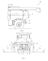
FIG. 1 is a simplified, fragmentary side view of the rear end of a representative agricultural combine that has associated therewith a crop residue distribution system, including a spreader that includes a pair of spreader paddles for spreading crop residue; -
FIG. 2 is a rear view of such combine, generally depicting the location of the crop residue distribution system and certain components thereof; -
FIG. 3 is a perspective view of a portion of the spreader showing the positioning of the spreader paddles relative to a flow guide element of the present invention; -
FIG. 4 is an exploded perspective view of the flow guide elementFIG. 3 ; -
FIG. 5 is a representation of a flow guide element such as it might appear relative to the spreader paddles in a given position; -
FIG. 6 is a cross-section taken along line 6-6 ofFIG. 5 of a meshing spreader paddle and flow guide element; -
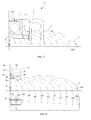
FIG. 7 is a simplified schematic rear view of a right rear end of the combine and spreader, showing a representative pattern of crop residue distribution by the flow distributor apparatus on that side of the spreader; -
FIG. 8 is a simplified schematic rear view of a right rear end of the spreader and flow distributor apparatus, in combination with a bottom view thereof, diagrammatically illustrating characteristics of a pattern of crop residue flow distribution therefrom; and -
FIG. 9 is a cross-section taken along line 6-6 ofFIG. 5 of a meshing spreader paddle and flow guide element according to another embodiment of the invention. - Wherever possible, the same reference numbers will be used throughout the drawings to refer to the same or like parts.
- Referring now to the drawings, wherein preferred embodiments of the present invention are shown, wherein like numerals refer to like items,
FIG. 1 depicts arear end 20 of a self-propelledagricultural combine 22, including a verticalcrop residue spreader 24 operable for spreading straw, stalks, or other crop residue and trash that has been separated from the grain of the crops by a threshing mechanism (not shown) of combine 22 located forwardly ofrear end 20. The straw, stalks and the like are propelled rearwardly by rotating beaters or the like (also not shown) from the threshing mechanism and downwardly through a rear cavity of combine 22 tovertical spreader 24, which includes within ahousing 26 of sheet metal or other construction, components for effecting the spread and optional chopping of crop residue thereby, all in the well known manner. - With further reference to
FIG. 2 , where, for purposes of clarity, certain elements or components associated with the rear or aft portion of the back sheet or back plate of thespreader 24 are not necessarily shown,spreader 24 is depicted including a pair of side by siderotary impellers rotational axes impellers - Impellers 28 and 30, which may form or include paddles of appropriate sizes and configurations for the uses intended, are rotated by suitable driving elements, such as by conventionally constructed and operable hydraulic motors powered by pressurized hydraulic fluid received from a pump (not shown) of
combine 22, an electric motor, belt, or the like, again in the well known manner.Rotational axes spreader 24 oncombine 22, which can be optionally variable and adjustable in the well known manner. However, although as shown inFIG. 8 as a 90 degree projection of a generally horizontally orientedspreader 24,spreader 24 may alternately be oriented in a generally vertical position. In another embodiment, the spreader could be oriented between a generally vertical position and a generally horizontal position. -
Housing 26 ofspreader 24 includes spaced, opposed radial side walls, and arear wall 36, sometimes referred to as the back sheet or back plate of the spreader, extending therebetween across the width ofspreader 24, defining an internalcavity containing impellers Housing 26 defines a forwardly and upwardly facing inlet opening 45 for receiving the residue flow from the threshing system, and a downwardly facing discharge opening 38 positioned generally opposite inlet opening 45, through which the residue is propelled downwardly and in opposite sideward directions byimpellers - Residue flow within
housing 26 is propelled by the rotatingimpellers housing 26 through discharge opening 38 at a corresponding speed. In the instance whereinspreader 24 is solely used for spreading, the speed imparted to the residue byimpellers combine 22 for deposit on regions of the agricultural field over which combine 22 has just traveled and from which the crops have been harvested. - As noted hereinabove, it is generally desirable to distribute the crop residue discharged by
impellers combine 22, which width is typically defined by the overall width of a harvesting head ofcombine 22, which width can be as much as 9 to 12 m (30 to 40 feet) in the instance of some heads currently in use. Thus, it is desirable thatrotary impellers combine 22, and possibly farther as combine headers of greater width are introduced. Impellers 28 and 30 can be suitably configured and rotated at a sufficient velocity for propelling crop residue such as, but not limited to, chopped straw, stems and branches, cobs and the like, the required distance of up to one-half the width of a header currently being used, by a conventional hydraulic motor or any other suitable driver as mentioned above. Problems to be currently overcome, however, are distributing the crop residue substantially evenly over this distance of up to about 6 m or so, including in the region of a swath directly beneathspreader 24, while minimizing the amount of increase of rotational speed of the impellers, or without increasing the swath diameter of the impellers, either of which would require an increase in power from the combine in order to operate. - Flow distributor or flow
distribution system 40 is primarily associated withspreader 24, and especially with back sheet or backplate 36 thereof. As depicted collectively inFIGS. 3-6 , one possible embodiment offlow distribution system 40 according to the present invention may include a flow guide element portion, flow guide or flowguide element 42 disposed withinhousing 26 ofspreader 24 abutting backsheet 36. As shown, flowguide element 42, which is preferably of suitable, rigid construction having a low coefficient of friction, such as of sheet metal, or plastics, or having a low-friction coating applied to the surface of the flow guide element material, is depicted having anapex portion 44 includingpivotal connections 47 with opposed wing orarm portions free end portions edges longitudinal surfaces arm portions vanes 66 defining aclearance region 67 with spreader paddle members or spreader paddles 70 ofimpellers Flow guide element 42 serves to guide and carry the received crop residue flow sidewardly outwardly away fromspreader 24 and to distribute the crop residue, illustrated by strings of oppositely directed arrows C and downwardly directed arrows D inFIG. 2 , for distribution in a pattern on a field or patternedfield residue 71, as shown inFIG. 2 . - For purposes of clarity in the further discussion of the present invention, it should be understood that, within the context of these discussions, the term "sideward" is meant to refer to or identify a direction generally transverse to the fore and aft directions, the term "sidewardly outwardly" is meant to refer to a sideward direction away from a center line 72 (
FIG. 2 ) ofspreader 24, and the term "sidewardly inwardly" is meant to refer to a sideward direction towards or closer tocenter line 72. - As may be better observed with reference to
FIGS. 3-5 , theflow guide element 42 is typically positioned with itsaft end 56 in close proximity to, or in abutment with, the front side of back sheet or backplate 36. As shown in the figures, wing orarm portions pivotal connection 47 withapex portion 44 and also forms a pivotal connection with anadjusting mechanism 78. The adjustment of adjustingmechanism 78 may be effected by any appropriate means, including, but not limited to, mechanical, hydraulic, and electric means, including through the use of hydraulic cylinders and linear actuators, and in any manner appropriate for the combine and spreader in use. In one embodiment adjusting mechanism may be operatively connected to botharm portions - As may also be observed from
FIGS. 3-5 , for the particular form offlow guide element 42 disclosed therein,apex portion 44 functions as a center flow divider, which is depicted as being of a projecting generally triangular shape, and extending forwardly fromback plate 36 so as to be disposed betweenimpellers center line 72, for dividing crop residue flow therebetween and for directing the bulk of residue flow fromimpeller 28 and its spreader paddles towards wing orarm portion 46 offlow guide element 42 and fromimpeller 30 and its spreader paddles towards wing orarm portion 48 offlow guide element 42. - As shown collectively in
FIGS. 4-6 , undulations orvanes 66 may be formed in at least one ofarm portions vanes 66 may include a tapered leadingedge 68 to prevent an accumulation of crop residue thereon. Leadingedge 68 may be linear or nonlinear or curved and may have a profile different from the rest ofarm portions vanes 66 define a closed geometry, such as a tapered trapezoidal profile (FIG. 6 ) although in one embodiment the profile of thevanes 66 may be of a substantially constant width. In one embodiment, as shown inFIG. 6 ,vanes 66 include a base width W, narrowing to a tip width V. However, in another embodiment, the tip width V may be greater than the base width W. Although a pair ofvanes 66 is shown extending from each ofarm portions vane 66 or more than twovanes 66 may be formed in the arm portions. Whilevanes 66 are shown having an identical or a similar size and/or profile relative to each other, in other embodiments, the vanes may be sized differently relative to each other, as well as having similar or different lengths L (FIG. 4 ) relative to each other. As further shown in the figures, one ormore vanes 80 may be formed inapex portion 44. - As shown in
FIGS. 4-6 ,vanes vanes circumferential clearance regions 67 in which corresponding features 76 formed inends 74 are aligned withvanes vanes FIG. 6 , overlaps 69 betweenvanes clearance regions 67, spreader paddles 70 operate to "comb" crop residue fromlongitudinal surfaces arm portions FIG. 9 ,vanes clearance region 67, do not overlap each other, although "combing" is still considered to occur. As a result of such "combing", the interaction between spreader paddles 70 and crop residue is increased, resulting in further operational efficiency increases of the spreader. In addition, the reduced clearance between ends 74 of spreader paddles 70 andarm portions vanes longitudinal surfaces arm portions longitudinal surfaces longitudinal surfaces vanes vanes - In operation, as the crop residue enters the top of the
spreader 24, thecounter-rotating impellers apex portion 44 operating as a center divider, which will direct residue flowing downwardly therealong towardsflow guide element 42. The distance which spreader 24 can discharge crop residue is related to the clearance between the tips of the spreader paddles as the paddles rotate past theflow guide element 42. However, by use ofvanes repositioning arm portions mechanism 78 to change the clearance between ends 74 of spreader paddles 70 andlongitudinal surfaces clearance region 67 between ends 74 and surfaces 62, 64 during rotational operation of the paddles relative to thesurfaces clearance region 67 may or may not include overlap 69 (seeFIGS. 6 ,9 ) the spread width of crop residue can be both better controlled and increased, with a minimal increase in torque required to rotate the spreader paddles. That is, due at least in part to the increased focus of the flow of the crop residue for discharge from thespreader 24 made possible by reduced clearance and/or meshing betweenvanes arm portions paddles 70 andlongitudinal surfaces mechanism 78, as discussed previously, both the amount of sidewardly outwardly throw of the crop residue and well as improved directional control of the crop residue can be effected. -
FIGS. 7 and 8 illustrate cropresidue distribution patterns 350 that are possible using a flow distributor apparatus of the present invention in cooperation with a vertical spreader such asspreader 24 oncombine 22. As has been discussed hereinabove, particularly in reference toFIG. 2 , a substantially even or uniform crop residue distribution pattern, denoted byline 350, can be achieved as between flows C and D, by making required adjustments of the position ofarm portions flow guide element 42, in the above discussed manners. The dots 360-382 inFIG. 8 illustrate approximate locations alongpattern 350 where crop residue flowing along the correspondingly numbered lines may be distributed on a field. - As will be appreciated from the foregoing description and discussion, as the clearance between
arm portion 46 and meshing of the surfaces of the arm portions, including the vanes, and the outer swept diameter of the spreader paddles ofimpeller 28 is increased, such as by actuation ofadjustment device 78, the throw of crop residue will be altered such that, by way of example, the throw that had before landed at dot 382 (FIG. 8 ), might now land atdot 374. Consequently, the flow of crop residue can be controllably effected. - In light of all the foregoing, it should thus be apparent to those skilled in the art that there has been shown and described a flow distributor apparatus, and method of use thereof, that can be utilized to provide a desired pattern of crop residue distribution therefrom to obtain a more uniform distribution of crop residue over a swath of an agricultural field from which the crop was harvested, especially under varying geographic and environmental conditions. However, it should also be apparent that, within the scope of the invention as defined by the accompanying claims, many changes are possible and contemplated, including in the details, materials, steps, and arrangements of parts which have been described and illustrated to explain the invention. Thus, while the foregoing description and discussion addresses certain preferred embodiments or elements of the invention, it should further be understood that concepts, as based upon the foregoing description and discussion, may be readily incorporated into or employed in other embodiments and constructions without departing from the scope of the invention as claimed.
Claims (12)
- A crop residue spreader (24) for use with a combine harvester (22), the spreader comprising:an inlet opening (45) at the top and/or front thereof for receiving crop residue;at least one rotary impeller (28/30) comprising a set of paddle members (70) having outer paddle ends (74);a flow guide element (42) comprising, for each rotary impeller (28/30), a laterally extending arm portion (46/48) including a surface extending longitudinally between ends (54, 56) of the flow guide element and defining a crop residue flow surface (62/64), extending generally circumferentially about and outwardly of a portion of the rotary impeller (28/30), thereby defining a clearance region (67) between the crop residue flow surface (62/64) and the paddle ends (74),the arm portion (46/48) being mounted to a pivotal connection (47) enabling adjustment of the clearance between the crop residue flow surface (62/64) and the paddle ends (74),characterized in that the clearance region (67) includes at least one undulation (66) formed in the arm portion (46/48).
- A spreader according to claim 1, wherein the at least one undulation comprises a vane (66) extending outwardly from the surface (62/64) of the arm portion (46/48) towards the rotary impeller (28/30).
- A spreader according to claim 1 or 2, wherein the at least one undulation (66) meshes with a feature (76) in the paddle ends (74).
- A spreader according to any of the preceding claims, wherein the undulation (66) is formed of a material having a low coefficient of friction.
- A spreader according to any of the preceding claims, wherein the clearance region comprises a plurality of undulations (66) formed in the arm portion (46/48).
- A spreader according to claim 5, wherein the undulations (66) have a different profile relative to each other.
- A spreader according to claim 5 or 6, wherein the undulations (66) have a different length relative to each other.
- A spreader according to any of the preceding claims, comprising an adjusting mechanism (78) connected to the arm portion (46/48) and operable to effect rotational movement of the arm portion about the pivotal connection (47) for adjustably varying the clearance between the crop residue flow surface (62/64) and the paddle ends (74) and thereby controllably distributing the crop residue in a desired pattern (350) over a field.
- A spreader according to any of the preceding claims, comprising a pair of counter-rotating impellers (28, 30), disposed generally side by side, and wherein the flow guide element (42) comprises:an apex portion (44) including a pair of crop residue flow surfaces; anda pair of opposed, laterally extending arm portions (46, 48) pivotally connected to the apex portion (44) at a pair of pivotal connections (47),wherein at least one undulation (80) is formed in at least one crop residue flow surface of the apex portion (44).
- A spreader according to claim 8, wherein the at least one undulation (80) in the at least one crop residue flow surface of the apex portion (44) has a leading edge that is linear or curved.
- A spreader according to claim 9 or10, when dependent on claim 8, wherein the adjusting mechanism (78) is disposed between the fore and aft ends (54, 56) of the flow guide element (42).
- A combine harvester (22) comprising a spreader according to any of the preceding claims.
Applications Claiming Priority (1)
| Application Number | Priority Date | Filing Date | Title |
|---|---|---|---|
| US13/557,801 US8834244B2 (en) | 2012-07-25 | 2012-07-25 | Flow distribution system for controlling application width of residual crop material |
Publications (2)
| Publication Number | Publication Date |
|---|---|
| EP2689655A1 true EP2689655A1 (en) | 2014-01-29 |
| EP2689655B1 EP2689655B1 (en) | 2015-11-18 |
Family
ID=48875575
Family Applications (1)
| Application Number | Title | Priority Date | Filing Date |
|---|---|---|---|
| EP13178102.3A Active EP2689655B1 (en) | 2012-07-25 | 2013-07-25 | Flow distribution system for controlling application width of residual crop material |
Country Status (2)
| Country | Link |
|---|---|
| US (1) | US8834244B2 (en) |
| EP (1) | EP2689655B1 (en) |
Cited By (1)
| Publication number | Priority date | Publication date | Assignee | Title |
|---|---|---|---|---|
| EP3153002A1 (en) | 2015-10-05 | 2017-04-12 | CNH Industrial Belgium nv | A crop residue spreader |
Families Citing this family (15)
| Publication number | Priority date | Publication date | Assignee | Title |
|---|---|---|---|---|
| US10143131B2 (en) | 2011-10-18 | 2018-12-04 | Cnh Industrial America Llc | Method and apparatus to control residue width |
| US20150264864A1 (en) * | 2014-03-20 | 2015-09-24 | Deere & Company | Mog sensing system for a residue spreader |
| US9521808B2 (en) * | 2014-11-19 | 2016-12-20 | Cnh Industrial America Llc | Harvester chaff pan assembly with moveable deflector components |
| US20160199992A1 (en) * | 2015-01-08 | 2016-07-14 | The Gillette Company | Razor cartridge with a printed lubrication member |
| DE202015000189U1 (en) * | 2015-01-16 | 2016-04-20 | Redexim Handel- En Exploitatie Maatschappij B.V. | spreader |
| US20170112055A1 (en) * | 2015-10-27 | 2017-04-27 | Cnh Industrial America Llc | Agricultural harvester residue spreader automation |
| CN106561172B (en) | 2016-10-25 | 2019-01-08 | 江苏大学 | A kind of longitudinal axial flow combined harvester Lysimachia sikokiana crushes adaptive scattering mechanism and its control method |
| US10820502B2 (en) * | 2018-10-01 | 2020-11-03 | Cnh Industrial America Llc | Compensation method for wind effects upon residue distribution |
| US11510364B2 (en) | 2019-07-19 | 2022-11-29 | Deere & Company | Crop residue based field operation adjustment |
| US11758847B2 (en) | 2019-09-19 | 2023-09-19 | Deere & Company | Residue quality assessment and performance system for a harvester |
| EP4173466B1 (en) * | 2021-11-02 | 2024-08-21 | CNH Industrial Belgium N.V. | Adjustable spreader system for an agricultural harvester |
| GB202218830D0 (en) * | 2022-12-14 | 2023-01-25 | Agco Int Gmbh | Crop residue spreader arrangement |
| US12457934B2 (en) | 2023-01-09 | 2025-11-04 | Deere & Company | Residue sensing and cleaning system |
| US12310285B2 (en) | 2023-02-27 | 2025-05-27 | Deere & Company | Agricultural operation evaluation system and method |
| US12550819B2 (en) | 2023-04-12 | 2026-02-17 | Deere & Company | Residue sensor protection on a harvester |
Citations (4)
| Publication number | Priority date | Publication date | Assignee | Title |
|---|---|---|---|---|
| US20030109293A1 (en) * | 2001-12-12 | 2003-06-12 | Wolters Joshua J. | Multi-tier crop residue flow guide for an agricultural combine |
| US20030109294A1 (en) * | 2001-12-12 | 2003-06-12 | Wolters Joshua J. | Vertical crop residue chopper and spreader |
| EP2000019A1 (en) * | 2007-06-05 | 2008-12-10 | CNH Belgium N.V. | A stationary knife assembly for a chopper assembly |
| US20090111548A1 (en) * | 2007-10-31 | 2009-04-30 | Koen Landuyt | Residue splitter |
Family Cites Families (27)
| Publication number | Priority date | Publication date | Assignee | Title |
|---|---|---|---|---|
| US3186460A (en) | 1961-07-20 | 1965-06-01 | Frederick Joseph | Straw chopping apparatus |
| DE3474248D1 (en) * | 1984-07-19 | 1988-11-03 | Deere & Co | Chopper device, especially for harvesting machines |
| DE3704755A1 (en) * | 1987-02-16 | 1988-08-25 | Claas Ohg | Combine harvester with a device for distributing the GRAIN-SPREAD MIXTURE |
| DE3834102A1 (en) * | 1988-10-07 | 1990-04-12 | Claas Ohg | HARVESTER |
| US5232405A (en) * | 1992-01-07 | 1993-08-03 | Redekop Leo L | Apparatus for chopping and discharging straw from a combine harvester |
| US5421777A (en) | 1993-07-02 | 1995-06-06 | New Holland North America, Inc. | Tailings return system for combine harvester |
| DE4431802A1 (en) * | 1994-09-07 | 1996-03-14 | Claas Ohg | Add-on chopper with wide distributor discharge for material to be shredded, in particular straw / chaff mixture for / on a combine harvester |
| US5482508A (en) * | 1995-03-31 | 1996-01-09 | Redekop; Leo L. | Apparatus for chopping and discharging straw from a combine harvester |
| SE504681C2 (en) * | 1995-09-06 | 1997-04-07 | Rekordverken Ab | Cutting machine at combine with a fan for extra air |
| DE19535175A1 (en) * | 1995-09-25 | 1996-03-21 | Jakobi Wilhelm Dipl Ing Fh | Straw chopper using drum with knives |
| DE19753486B4 (en) * | 1997-12-02 | 2006-02-16 | Deere & Company, Moline | chopping |
| DE19908111C1 (en) | 1999-02-25 | 2000-07-27 | Claas Selbstfahr Erntemasch | Thresher with discharge blowers for straw chaff mixture has material outlet opening of chopper in same plane as inlet opening of discharge blower |
| DE10107776A1 (en) * | 2001-02-16 | 2003-05-08 | Claas Selbstfahr Erntemasch | Conveying elements and shredding device for agricultural machinery |
| US6719627B2 (en) * | 2001-12-17 | 2004-04-13 | Case Corporation | Multi-position linkage and locking mechanism for a crop residue spreader and/or chopper |
| US6547169B1 (en) * | 2002-06-25 | 2003-04-15 | Case Corporation | Crop residue spreader for an agricultural combine |
| US6840854B2 (en) * | 2002-08-30 | 2005-01-11 | Leo Redekop | Apparatus for chopping and discharging straw from a combine harvester |
| US6769980B2 (en) | 2002-12-30 | 2004-08-03 | Case, Llc | Crop residue flow guide with flow-through capability for a rotary crop residue spreader of an agricultural combine |
| US7104883B2 (en) * | 2003-06-23 | 2006-09-12 | Deere & Company | Straw chopper blade |
| DE10342922A1 (en) * | 2003-09-15 | 2005-05-19 | Claas Selbstfahrende Erntemaschinen Gmbh | Chopping and distribution device |
| US6893340B1 (en) * | 2003-12-09 | 2005-05-17 | Cnh America Llc | Rotary accelerating apparatus for a vertical straw and chaff spreader of an agricultural combine |
| US7297053B2 (en) * | 2004-07-16 | 2007-11-20 | Cnh America Llc | Rotary crop residue chopper apparatus with stiffener having air flow generating capability and method of making the same |
| US7223168B2 (en) * | 2005-08-01 | 2007-05-29 | Cnh America Llc | Adjustable crop residue flow distributor for a vertical spreader of an agricultural combine |
| US7390253B2 (en) | 2006-05-25 | 2008-06-24 | Cnh America Llc | Flow distributor apparatus for controlling spread width of a straw spreader |
| US7473169B2 (en) | 2007-02-28 | 2009-01-06 | Cnh America Llc | Adjustable axial rotor discharge deflector |
| US7487024B2 (en) * | 2007-04-26 | 2009-02-03 | Cnh America Llc | Apparatus and method for automatically setting operating parameters for a remotely adjustable spreader of an agricultural harvesting machine |
| EP2138024B1 (en) * | 2008-06-25 | 2011-08-17 | CNH Belgium N.V. | Active spreader for an agricultural combine |
| US8118650B2 (en) * | 2010-03-24 | 2012-02-21 | Cnh America Llc | Crop residue flow distributor for an agricultural combine |
-
2012
- 2012-07-25 US US13/557,801 patent/US8834244B2/en active Active
-
2013
- 2013-07-25 EP EP13178102.3A patent/EP2689655B1/en active Active
Patent Citations (4)
| Publication number | Priority date | Publication date | Assignee | Title |
|---|---|---|---|---|
| US20030109293A1 (en) * | 2001-12-12 | 2003-06-12 | Wolters Joshua J. | Multi-tier crop residue flow guide for an agricultural combine |
| US20030109294A1 (en) * | 2001-12-12 | 2003-06-12 | Wolters Joshua J. | Vertical crop residue chopper and spreader |
| EP2000019A1 (en) * | 2007-06-05 | 2008-12-10 | CNH Belgium N.V. | A stationary knife assembly for a chopper assembly |
| US20090111548A1 (en) * | 2007-10-31 | 2009-04-30 | Koen Landuyt | Residue splitter |
Cited By (1)
| Publication number | Priority date | Publication date | Assignee | Title |
|---|---|---|---|---|
| EP3153002A1 (en) | 2015-10-05 | 2017-04-12 | CNH Industrial Belgium nv | A crop residue spreader |
Also Published As
| Publication number | Publication date |
|---|---|
| US8834244B2 (en) | 2014-09-16 |
| EP2689655B1 (en) | 2015-11-18 |
| US20140031096A1 (en) | 2014-01-30 |
Similar Documents
| Publication | Publication Date | Title |
|---|---|---|
| US8834244B2 (en) | Flow distribution system for controlling application width of residual crop material | |
| US7281973B2 (en) | Adjustable crop residue flow distributor for a vertical spreader of an agricultural combine | |
| US8118650B2 (en) | Crop residue flow distributor for an agricultural combine | |
| US6602131B2 (en) | Multi-tier crop residue flow guide for an agricultural combine | |
| EP3592129B1 (en) | Spreader system for an agricultural harvester with an oscillating deflector | |
| US9801339B2 (en) | Regulator of residue flow for spreading devices on agricultural combines | |
| US8876583B2 (en) | Regulator of residue flow for spreading devices on agricultural combines | |
| EP2138024B1 (en) | Active spreader for an agricultural combine | |
| EP1859668B1 (en) | Distributor apparatus for controlling spread width of a straw spreader | |
| US9756782B2 (en) | Rear discharge mower deck with flow control baffles | |
| EP3409095B1 (en) | Agricultural combine with reversing chopper rotor | |
| EP4173466B1 (en) | Adjustable spreader system for an agricultural harvester | |
| EP1442651B1 (en) | Crop residue flow guide with flow-through capability for a rotary crop residue spreader of an agricultural combine. | |
| CA2935230C (en) | Method and apparatus for harvesting crop material | |
| EP4144201B1 (en) | Control of residue spread pattern by continuously varying distribution frequency | |
| EP3345472B1 (en) | Crop residue spreader for a combine harvester |
Legal Events
| Date | Code | Title | Description |
|---|---|---|---|
| PUAI | Public reference made under article 153(3) epc to a published international application that has entered the european phase |
Free format text: ORIGINAL CODE: 0009012 |
|
| AK | Designated contracting states |
Kind code of ref document: A1 Designated state(s): AL AT BE BG CH CY CZ DE DK EE ES FI FR GB GR HR HU IE IS IT LI LT LU LV MC MK MT NL NO PL PT RO RS SE SI SK SM TR |
|
| AX | Request for extension of the european patent |
Extension state: BA ME |
|
| RAP1 | Party data changed (applicant data changed or rights of an application transferred) |
Owner name: CNH INDUSTRIAL BELGIUM NV |
|
| 17P | Request for examination filed |
Effective date: 20140729 |
|
| RBV | Designated contracting states (corrected) |
Designated state(s): AL AT BE BG CH CY CZ DE DK EE ES FI FR GB GR HR HU IE IS IT LI LT LU LV MC MK MT NL NO PL PT RO RS SE SI SK SM TR |
|
| GRAP | Despatch of communication of intention to grant a patent |
Free format text: ORIGINAL CODE: EPIDOSNIGR1 |
|
| INTG | Intention to grant announced |
Effective date: 20150608 |
|
| GRAS | Grant fee paid |
Free format text: ORIGINAL CODE: EPIDOSNIGR3 |
|
| GRAA | (expected) grant |
Free format text: ORIGINAL CODE: 0009210 |
|
| AK | Designated contracting states |
Kind code of ref document: B1 Designated state(s): AL AT BE BG CH CY CZ DE DK EE ES FI FR GB GR HR HU IE IS IT LI LT LU LV MC MK MT NL NO PL PT RO RS SE SI SK SM TR |
|
| REG | Reference to a national code |
Ref country code: GB Ref legal event code: FG4D |
|
| REG | Reference to a national code |
Ref country code: CH Ref legal event code: EP |
|
| REG | Reference to a national code |
Ref country code: AT Ref legal event code: REF Ref document number: 761033 Country of ref document: AT Kind code of ref document: T Effective date: 20151215 |
|
| REG | Reference to a national code |
Ref country code: IE Ref legal event code: FG4D |
|
| REG | Reference to a national code |
Ref country code: DE Ref legal event code: R096 Ref document number: 602013003836 Country of ref document: DE |
|
| REG | Reference to a national code |
Ref country code: NL Ref legal event code: MP Effective date: 20160218 |
|
| REG | Reference to a national code |
Ref country code: LT Ref legal event code: MG4D |
|
| REG | Reference to a national code |
Ref country code: AT Ref legal event code: MK05 Ref document number: 761033 Country of ref document: AT Kind code of ref document: T Effective date: 20151118 |
|
| PG25 | Lapsed in a contracting state [announced via postgrant information from national office to epo] |
Ref country code: LT Free format text: LAPSE BECAUSE OF FAILURE TO SUBMIT A TRANSLATION OF THE DESCRIPTION OR TO PAY THE FEE WITHIN THE PRESCRIBED TIME-LIMIT Effective date: 20151118 Ref country code: ES Free format text: LAPSE BECAUSE OF FAILURE TO SUBMIT A TRANSLATION OF THE DESCRIPTION OR TO PAY THE FEE WITHIN THE PRESCRIBED TIME-LIMIT Effective date: 20151118 Ref country code: NO Free format text: LAPSE BECAUSE OF FAILURE TO SUBMIT A TRANSLATION OF THE DESCRIPTION OR TO PAY THE FEE WITHIN THE PRESCRIBED TIME-LIMIT Effective date: 20160218 Ref country code: IS Free format text: LAPSE BECAUSE OF FAILURE TO SUBMIT A TRANSLATION OF THE DESCRIPTION OR TO PAY THE FEE WITHIN THE PRESCRIBED TIME-LIMIT Effective date: 20160318 Ref country code: NL Free format text: LAPSE BECAUSE OF FAILURE TO SUBMIT A TRANSLATION OF THE DESCRIPTION OR TO PAY THE FEE WITHIN THE PRESCRIBED TIME-LIMIT Effective date: 20151118 Ref country code: HR Free format text: LAPSE BECAUSE OF FAILURE TO SUBMIT A TRANSLATION OF THE DESCRIPTION OR TO PAY THE FEE WITHIN THE PRESCRIBED TIME-LIMIT Effective date: 20151118 |
|
| PG25 | Lapsed in a contracting state [announced via postgrant information from national office to epo] |
Ref country code: GR Free format text: LAPSE BECAUSE OF FAILURE TO SUBMIT A TRANSLATION OF THE DESCRIPTION OR TO PAY THE FEE WITHIN THE PRESCRIBED TIME-LIMIT Effective date: 20160219 Ref country code: RS Free format text: LAPSE BECAUSE OF FAILURE TO SUBMIT A TRANSLATION OF THE DESCRIPTION OR TO PAY THE FEE WITHIN THE PRESCRIBED TIME-LIMIT Effective date: 20151118 Ref country code: AT Free format text: LAPSE BECAUSE OF FAILURE TO SUBMIT A TRANSLATION OF THE DESCRIPTION OR TO PAY THE FEE WITHIN THE PRESCRIBED TIME-LIMIT Effective date: 20151118 Ref country code: SE Free format text: LAPSE BECAUSE OF FAILURE TO SUBMIT A TRANSLATION OF THE DESCRIPTION OR TO PAY THE FEE WITHIN THE PRESCRIBED TIME-LIMIT Effective date: 20151118 Ref country code: LV Free format text: LAPSE BECAUSE OF FAILURE TO SUBMIT A TRANSLATION OF THE DESCRIPTION OR TO PAY THE FEE WITHIN THE PRESCRIBED TIME-LIMIT Effective date: 20151118 Ref country code: PL Free format text: LAPSE BECAUSE OF FAILURE TO SUBMIT A TRANSLATION OF THE DESCRIPTION OR TO PAY THE FEE WITHIN THE PRESCRIBED TIME-LIMIT Effective date: 20151118 Ref country code: PT Free format text: LAPSE BECAUSE OF FAILURE TO SUBMIT A TRANSLATION OF THE DESCRIPTION OR TO PAY THE FEE WITHIN THE PRESCRIBED TIME-LIMIT Effective date: 20160318 Ref country code: FI Free format text: LAPSE BECAUSE OF FAILURE TO SUBMIT A TRANSLATION OF THE DESCRIPTION OR TO PAY THE FEE WITHIN THE PRESCRIBED TIME-LIMIT Effective date: 20151118 |
|
| REG | Reference to a national code |
Ref country code: FR Ref legal event code: PLFP Year of fee payment: 4 |
|
| PG25 | Lapsed in a contracting state [announced via postgrant information from national office to epo] |
Ref country code: CZ Free format text: LAPSE BECAUSE OF FAILURE TO SUBMIT A TRANSLATION OF THE DESCRIPTION OR TO PAY THE FEE WITHIN THE PRESCRIBED TIME-LIMIT Effective date: 20151118 |
|
| REG | Reference to a national code |
Ref country code: DE Ref legal event code: R097 Ref document number: 602013003836 Country of ref document: DE |
|
| PG25 | Lapsed in a contracting state [announced via postgrant information from national office to epo] |
Ref country code: DK Free format text: LAPSE BECAUSE OF FAILURE TO SUBMIT A TRANSLATION OF THE DESCRIPTION OR TO PAY THE FEE WITHIN THE PRESCRIBED TIME-LIMIT Effective date: 20151118 Ref country code: RO Free format text: LAPSE BECAUSE OF FAILURE TO SUBMIT A TRANSLATION OF THE DESCRIPTION OR TO PAY THE FEE WITHIN THE PRESCRIBED TIME-LIMIT Effective date: 20151118 Ref country code: EE Free format text: LAPSE BECAUSE OF FAILURE TO SUBMIT A TRANSLATION OF THE DESCRIPTION OR TO PAY THE FEE WITHIN THE PRESCRIBED TIME-LIMIT Effective date: 20151118 Ref country code: SM Free format text: LAPSE BECAUSE OF FAILURE TO SUBMIT A TRANSLATION OF THE DESCRIPTION OR TO PAY THE FEE WITHIN THE PRESCRIBED TIME-LIMIT Effective date: 20151118 Ref country code: SK Free format text: LAPSE BECAUSE OF FAILURE TO SUBMIT A TRANSLATION OF THE DESCRIPTION OR TO PAY THE FEE WITHIN THE PRESCRIBED TIME-LIMIT Effective date: 20151118 |
|
| PLBE | No opposition filed within time limit |
Free format text: ORIGINAL CODE: 0009261 |
|
| STAA | Information on the status of an ep patent application or granted ep patent |
Free format text: STATUS: NO OPPOSITION FILED WITHIN TIME LIMIT |
|
| 26N | No opposition filed |
Effective date: 20160819 |
|
| PG25 | Lapsed in a contracting state [announced via postgrant information from national office to epo] |
Ref country code: SI Free format text: LAPSE BECAUSE OF FAILURE TO SUBMIT A TRANSLATION OF THE DESCRIPTION OR TO PAY THE FEE WITHIN THE PRESCRIBED TIME-LIMIT Effective date: 20151118 |
|
| PG25 | Lapsed in a contracting state [announced via postgrant information from national office to epo] |
Ref country code: BE Free format text: LAPSE BECAUSE OF FAILURE TO SUBMIT A TRANSLATION OF THE DESCRIPTION OR TO PAY THE FEE WITHIN THE PRESCRIBED TIME-LIMIT Effective date: 20151118 |
|
| REG | Reference to a national code |
Ref country code: CH Ref legal event code: PL |
|
| PG25 | Lapsed in a contracting state [announced via postgrant information from national office to epo] |
Ref country code: MC Free format text: LAPSE BECAUSE OF FAILURE TO SUBMIT A TRANSLATION OF THE DESCRIPTION OR TO PAY THE FEE WITHIN THE PRESCRIBED TIME-LIMIT Effective date: 20151118 |
|
| PG25 | Lapsed in a contracting state [announced via postgrant information from national office to epo] |
Ref country code: CH Free format text: LAPSE BECAUSE OF NON-PAYMENT OF DUE FEES Effective date: 20160731 Ref country code: LI Free format text: LAPSE BECAUSE OF NON-PAYMENT OF DUE FEES Effective date: 20160731 |
|
| REG | Reference to a national code |
Ref country code: IE Ref legal event code: MM4A |
|
| REG | Reference to a national code |
Ref country code: FR Ref legal event code: PLFP Year of fee payment: 5 |
|
| PG25 | Lapsed in a contracting state [announced via postgrant information from national office to epo] |
Ref country code: IE Free format text: LAPSE BECAUSE OF NON-PAYMENT OF DUE FEES Effective date: 20160725 |
|
| PG25 | Lapsed in a contracting state [announced via postgrant information from national office to epo] |
Ref country code: LU Free format text: LAPSE BECAUSE OF NON-PAYMENT OF DUE FEES Effective date: 20160725 |
|
| PG25 | Lapsed in a contracting state [announced via postgrant information from national office to epo] |
Ref country code: CY Free format text: LAPSE BECAUSE OF FAILURE TO SUBMIT A TRANSLATION OF THE DESCRIPTION OR TO PAY THE FEE WITHIN THE PRESCRIBED TIME-LIMIT Effective date: 20151118 Ref country code: HU Free format text: LAPSE BECAUSE OF FAILURE TO SUBMIT A TRANSLATION OF THE DESCRIPTION OR TO PAY THE FEE WITHIN THE PRESCRIBED TIME-LIMIT; INVALID AB INITIO Effective date: 20130725 |
|
| PG25 | Lapsed in a contracting state [announced via postgrant information from national office to epo] |
Ref country code: MT Free format text: LAPSE BECAUSE OF NON-PAYMENT OF DUE FEES Effective date: 20160731 Ref country code: MK Free format text: LAPSE BECAUSE OF FAILURE TO SUBMIT A TRANSLATION OF THE DESCRIPTION OR TO PAY THE FEE WITHIN THE PRESCRIBED TIME-LIMIT Effective date: 20151118 Ref country code: TR Free format text: LAPSE BECAUSE OF FAILURE TO SUBMIT A TRANSLATION OF THE DESCRIPTION OR TO PAY THE FEE WITHIN THE PRESCRIBED TIME-LIMIT Effective date: 20151118 |
|
| REG | Reference to a national code |
Ref country code: FR Ref legal event code: PLFP Year of fee payment: 6 |
|
| PG25 | Lapsed in a contracting state [announced via postgrant information from national office to epo] |
Ref country code: BG Free format text: LAPSE BECAUSE OF FAILURE TO SUBMIT A TRANSLATION OF THE DESCRIPTION OR TO PAY THE FEE WITHIN THE PRESCRIBED TIME-LIMIT Effective date: 20151118 |
|
| PG25 | Lapsed in a contracting state [announced via postgrant information from national office to epo] |
Ref country code: AL Free format text: LAPSE BECAUSE OF FAILURE TO SUBMIT A TRANSLATION OF THE DESCRIPTION OR TO PAY THE FEE WITHIN THE PRESCRIBED TIME-LIMIT Effective date: 20151118 |
|
| REG | Reference to a national code |
Ref country code: DE Ref legal event code: R082 Ref document number: 602013003836 Country of ref document: DE Representative=s name: MEISSNER BOLTE PATENTANWAELTE RECHTSANWAELTE P, DE |
|
| PGFP | Annual fee paid to national office [announced via postgrant information from national office to epo] |
Ref country code: DE Payment date: 20250728 Year of fee payment: 13 |
|
| PGFP | Annual fee paid to national office [announced via postgrant information from national office to epo] |
Ref country code: IT Payment date: 20250721 Year of fee payment: 13 |
|
| PGFP | Annual fee paid to national office [announced via postgrant information from national office to epo] |
Ref country code: GB Payment date: 20250722 Year of fee payment: 13 |
|
| PGFP | Annual fee paid to national office [announced via postgrant information from national office to epo] |
Ref country code: FR Payment date: 20250725 Year of fee payment: 13 |