EP2689641B1 - Plasma torch systems having improved plasma nozzles - Google Patents
Plasma torch systems having improved plasma nozzles Download PDFInfo
- Publication number
- EP2689641B1 EP2689641B1 EP12712832.0A EP12712832A EP2689641B1 EP 2689641 B1 EP2689641 B1 EP 2689641B1 EP 12712832 A EP12712832 A EP 12712832A EP 2689641 B1 EP2689641 B1 EP 2689641B1
- Authority
- EP
- European Patent Office
- Prior art keywords
- nozzle
- plasma
- orifice
- inner diameter
- approximately
- Prior art date
- Legal status (The legal status is an assumption and is not a legal conclusion. Google has not performed a legal analysis and makes no representation as to the accuracy of the status listed.)
- Revoked
Links
- 238000005520 cutting process Methods 0.000 claims description 24
- RYGMFSIKBFXOCR-UHFFFAOYSA-N Copper Chemical compound [Cu] RYGMFSIKBFXOCR-UHFFFAOYSA-N 0.000 claims description 3
- 229910052802 copper Inorganic materials 0.000 claims description 3
- 239000010949 copper Substances 0.000 claims description 3
- 239000007769 metal material Substances 0.000 claims description 3
- 239000002184 metal Substances 0.000 description 6
- 229910052751 metal Inorganic materials 0.000 description 6
- 238000013461 design Methods 0.000 description 5
- 239000004020 conductor Substances 0.000 description 3
- 239000000463 material Substances 0.000 description 3
- 150000002739 metals Chemical class 0.000 description 3
- 230000007613 environmental effect Effects 0.000 description 2
- 230000007246 mechanism Effects 0.000 description 2
- 238000013021 overheating Methods 0.000 description 2
- 238000012546 transfer Methods 0.000 description 2
- 230000001052 transient effect Effects 0.000 description 2
- 238000010521 absorption reaction Methods 0.000 description 1
- 230000015556 catabolic process Effects 0.000 description 1
- 230000008859 change Effects 0.000 description 1
- 230000005495 cold plasma Effects 0.000 description 1
- -1 copper Chemical class 0.000 description 1
- 238000006731 degradation reaction Methods 0.000 description 1
- 239000004973 liquid crystal related substance Substances 0.000 description 1
- 238000000034 method Methods 0.000 description 1
- 238000012986 modification Methods 0.000 description 1
- 230000004048 modification Effects 0.000 description 1
- 239000012768 molten material Substances 0.000 description 1
- XLYOFNOQVPJJNP-UHFFFAOYSA-N water Substances O XLYOFNOQVPJJNP-UHFFFAOYSA-N 0.000 description 1
- 238000003466 welding Methods 0.000 description 1
Images


Classifications
-
- H—ELECTRICITY
- H05—ELECTRIC TECHNIQUES NOT OTHERWISE PROVIDED FOR
- H05H—PLASMA TECHNIQUE; PRODUCTION OF ACCELERATED ELECTRICALLY-CHARGED PARTICLES OR OF NEUTRONS; PRODUCTION OR ACCELERATION OF NEUTRAL MOLECULAR OR ATOMIC BEAMS
- H05H1/00—Generating plasma; Handling plasma
- H05H1/24—Generating plasma
- H05H1/26—Plasma torches
- H05H1/32—Plasma torches using an arc
- H05H1/34—Details, e.g. electrodes, nozzles
-
- B—PERFORMING OPERATIONS; TRANSPORTING
- B23—MACHINE TOOLS; METAL-WORKING NOT OTHERWISE PROVIDED FOR
- B23K—SOLDERING OR UNSOLDERING; WELDING; CLADDING OR PLATING BY SOLDERING OR WELDING; CUTTING BY APPLYING HEAT LOCALLY, e.g. FLAME CUTTING; WORKING BY LASER BEAM
- B23K10/00—Welding or cutting by means of a plasma
-
- H—ELECTRICITY
- H05—ELECTRIC TECHNIQUES NOT OTHERWISE PROVIDED FOR
- H05H—PLASMA TECHNIQUE; PRODUCTION OF ACCELERATED ELECTRICALLY-CHARGED PARTICLES OR OF NEUTRONS; PRODUCTION OR ACCELERATION OF NEUTRAL MOLECULAR OR ATOMIC BEAMS
- H05H1/00—Generating plasma; Handling plasma
- H05H1/24—Generating plasma
- H05H1/26—Plasma torches
- H05H1/32—Plasma torches using an arc
- H05H1/34—Details, e.g. electrodes, nozzles
- H05H1/3478—Geometrical details
Definitions
- the invention relates generally to plasma cutting systems and, more particularly, to nozzles for a plasma torch for such systems.
- a plasma cutting system that creates plasma (from high temperature ionized gas) for the cutting of metal or other electrically conductive material.
- an electrical arc converts a gas (e.g., compressed air) into plasma, which is sufficiently hot to melt a metal workpiece while the pressure of the gas blows away the molten metal.
- the electrical arc is typically initiated in a plasma torch, and gas flows through the torch.
- a plasma torch is used to direct and control the plasma for cutting.
- the plasma torch typically includes a variety of components, such as plasma nozzles or tips that focus plasma gas into a constricted arc, that enable its direction and control.
- the hot plasma cuts the workpiece along that path of the torch tip.
- the plasma torch nozzles are typically utilized in this manner, the nozzles are often manufactured from metals, such as copper, that have high thermal and electrical conductivity.
- US 5,266,776 discloses a plasma arc cutting tip with a chamfer tip edge.
- US 5,880,426 discloses a water cooled nozzle tip.
- WO 2010/067306 discloses a cold plasma device with a tubular electrically conductive housing.
- a nozzle for a plasma torch includes a body having a first end, a second end having an exit orifice disposed therein, and a passageway extending from the first end to the second end.
- the passageway enables the flow of plasma gas from the first end, through the passageway, and to the exit orifice. Greater than or equal to approximately 50% of an overall mass of the body is distributed between the second end and a midpoint of the body with respect to a longitudinal length of the body.
- a nozzle for a plasma torch in another embodiment, includes a body having a first end and a second end having a plasma gas exit orifice disposed therein. A longitudinal distance from the first end to the center of mass of the body is greater than or equal to approximately 43% of a longitudinal length of the body.
- a nozzle for a plasma torch in another embodiment, includes a body having a first end and a second end having a plasma gas exit orifice disposed therein. A longitudinal distance from the first end to the center of mass of the body is greater than or equal to approximately 48% of a longitudinal length of the body.
- a nozzle for a plasma torch in another embodiment, includes a body having a first end, a second end having a plasma gas exit orifice disposed therein, a first portion extending from the first end along a longitudinal length of the body, an orifice portion extending from the second end along the longitudinal length of the body, and a middle portion disposed between the first portion and the orifice portion.
- An orifice ratio defined by an average wall thickness of the orifice portion divided by an inner diameter of the orifice portion is greater than or equal to approximately 3.6.
- a middle portion ratio defined by an average wall thickness of the middle portion divided by an inner diameter of the middle portion is greater than or equal to approximately 0.27.
- a nozzle for a plasma torch in another embodiment, includes a body having a first end, a second end having a plasma gas exit orifice disposed therein, an orifice portion extending from the second end along the longitudinal length of the body, and a second portion extending from the first end along a longitudinal length of the body to the orifice portion.
- An orifice ratio defined by an average wall thickness of the orifice portion divided by an inner diameter of the orifice portion is greater than or equal to approximately 3.5.
- a plasma torch assembly in another embodiment, includes a body and an electrode disposed within the body and adapted to receive power to enable generation of a plasma arc between the electrode and the workpiece.
- the assembly also includes a nozzle having a nozzle body having a first end and a second end having a plasma gas exit orifice disposed therein.
- a longitudinal distance from the first end to the center of mass of the nozzle body is greater than or equal to approximately 48% of a longitudinal length of the nozzle body, and an outer surface of the electrode and an inner annular wall of the nozzle define a plasma arc chamber.
- a plasma cutting system in another embodiment, includes a plasma torch having a nozzle having a body having a first end and a second end having a plasma gas exit orifice disposed therein. A longitudinal distance from the first end to the center of mass of the body is greater than or equal to approximately 48% of a longitudinal length of the body.
- the system also includes a power source adapted to couple to the plasma torch and to provide a current to the plasma torch for generating a pilot arc and for maintaining a plasma cutting arc.
- the nozzle may include a body having greater than or equal to approximately 50% of the overall mass of the body distributed toward the exit orifice portion of the nozzle.
- the foregoing feature of presently disclosed embodiments may offer a variety of advantages over traditional systems that do not include an increased concentration of mass near the exit orifice.
- presently contemplated embodiments may increase the local thermal capacity of the nozzle while reducing or eliminating the likelihood of overheating of the nozzle during operation.
- the face of the nozzle may be exposed to high temperatures arising from the plasma arc and blow back of molten material from the cut.
- presently disclosed embodiments of the nozzle may be more robust and resistant to wear from the arc and spatter than conventional designs.
- FIG. 1 is a perspective view illustrating an embodiment of a portable plasma cutting system 10.
- the illustrated plasma cutting system 10 includes a torch power unit 12 coupled to a plasma torch 14 and a workpiece clamp 16 via a torch cable 15 and a workpiece cable 17, respectively.
- the plasma torch 14 may include various features that provide improved performance and durability and longer usage life.
- the plasma torch 14 may include a nozzle 19 capable of focusing plasma gas into a constricted arc during a plasma cutting operation.
- a variety of improvements may be realized as compared to conventional designs.
- the torch power unit 12 may be coupled to a power source (e.g., a power grid or a motor-driven generator) via a power cable 18.
- the power source may provide a current to the torch 14 for starting and generating a pilot arc, and for maintaining plasma and a cutting arc.
- the power unit 12 may be configured to supply a suitable voltage and current to create an electrical circuit from the unit 12, along the cable 15 to the torch 14, across a gap between the torch 14 and a work piece (e.g., as an electrical arc), through the work piece to the clamp 16, through the cable 17 back to the unit 12.
- the power unit 12 includes an enclosure 20 defining a generally closed volume to support various circuits, sensor features, control features, and gas supply features (e.g., air compressor).
- the system 10 may include sensors and controls to adjust the power unit 10 to account for various conditions, e.g., altitude, temperature, pressure, and so forth.
- the illustrated system 10 also may include a handle 22 on the top side of the enclosure 20 to enable easier transportation of the system 10.
- the illustrated system 10 also may include a latching mechanism 24 that may secure the torch 14, the cable 17, the clamp 16, and/or the power cable 18.
- the enclosure 20 may also include vents 28 to relieve heat and/or pressure inside the system 10. It should be noted that in other embodiments, additional vents may be located on other panels of the enclosure 20.
- a control panel 38 is included at an end of the power unit 12.
- the control panel 38 may include various control inputs, indicators, displays, electrical outputs, air outputs, and so forth.
- a user input 40 may include a button, knob, or switch configured to enable selection of a mode of operation (e.g., plasma cut, gouge, etc.), power on/off, an output current level, gas (e.g., air) flow rate, gas (e.g., air) pressure, gas type, a work piece type, a control type (e.g., manual or automatic feedback control), or a combination thereof.
- the control panel 34 may also include various indicators 42 to provide feedback to the user.
- the indicators 42 may include one or more light emitting diodes (LED) and/or liquid crystal displays (LCD) to display on/off status, current level, voltage level, gas (e.g., air) pressure, gas (e.g., air) flow, environmental conditions (e.g., altitude, temperature, pressure, etc.), or any other parameter.
- the indicators 42 may include an LED or LCD that displays a trouble or warning indicator if there is a problem with the system 10.
- Embodiments of the control panel 38 may include any number inputs and outputs, such as welding methods, air compressor settings, oil pressure, oil temperature, and system power.
- the user inputs 40 and indicators 42 may be electrically coupled to control circuitry and enable a user to set and monitor various parameters of the system 10.
- the indicators 42 may display environmental conditions (e.g., altitude, temperature, pressure, etc.) that prompt a user to manually adjust the current, voltage, gas flow rate, gas pressure, or other operational parameters, or a combination thereof.
- the plasma torch 14 includes a handle 44 and a trigger 46 with a guard, as well as the nozzle 19, which may conform to a variety of implementation-specific features, as described below with respect to FIGS. 2-4 .
- the clamp 16 includes an electrically conductive material clamping portion 48 having insulated handles 50.
- the power cable 18 includes a plug 52 for connection to a power source such as a wall socket or a motor-driven generator.
- the plug 52 may be configured to work with a variety of sockets or outlets, and the system 10 may receive different power sources, such as AC 50/60 Hz, 400 Hz, single or three phase 120V, 230V, 400V, 460V, 575V, any voltage in between such voltages, voltages exceeding the upper limit voltage, voltages below the lower limit voltage, and so forth.
- the illustrated plasma cutting system 10 is merely an example, and in other embodiments, the system 10 is subject to a variety of implementation-specific modifications, as would be understood by one skilled in the art.
- the power unit 12 may be configured as a stationary, rather than a portable, unit.
- the control panel 38 may include fewer or additional buttons, knobs, and so forth, as dictated by the demands of the given application.
- the plasma torch nozzles shown and described herein may be utilized with any plasma cutting torch associated with any plasma cutting system.
- FIG. 2 is a cross sectional view of an embodiment of the plasma torch nozzle 19 having an improved mass distribution in accordance with a presently disclosed embodiment.
- the nozzle 19 includes a body 60 having a first end 62 and a second end 64.
- an exit orifice 66 is disposed in the second end 64 of the body 60, which has a tapered edge 67.
- An internal passageway 68 extends from the first end 62 to the second end 64.
- an inner annular wall 70 of the nozzle 19 defines a series of portions along a longitudinal length 72 of the body 60 having a midpoint 73 defined by midpoint length 75.
- the illustrated body 60 includes a portion 74 proximate to the first end 62 and included in a first end portion 78, a middle portion 76, and an orifice portion 77 proximate to the second end 64.
- a length of the orifice portion 77 is defined by orifice portion length 87
- a length of the middle portion 76 is defined by middle portion length 89
- a length of the first end portion 78 is defined by first end portion length 91.
- a substantially perpendicular annular step 80 is included in the first end portion 78 while a recessed annular or angled step 82 is provided in the middle portion 76.
- the foregoing structure defines a first inner diameter 84, a second inner diameter 86, and a third inner diameter 88 of the body 60.
- the provided plasma torch nozzle 19 may include one or more features resulting in an increased concentration of mass proximate to the exit orifice 66 of the nozzle body 60 and, thus, improving the robustness and resistivity to heat of the nozzle 19 during use in a plasma cutting operation.
- a ratio of the average wall thickness to the inner diameter of certain portions of the body 60 may be improved compared to conventional designs. More specifically, an average wall thickness of the orifice portion 77 may be given by the cross sectional area indicated by hatched portion 97 in FIG. 2 divided by the orifice length 87.
- This average wall thickness of the orifice portion 77 may then be divided by the inner diameter of the orifice portion 77 to give an orifice ratio of the average wall thickness to the inner diameter.
- the orifice ratio may be greater than or equal to approximately 3.25. In another embodiment, the orifice ratio may be greater than or equal to approximately 3.6. Still further, in other embodiments, the orifice ratio may be greater than or equal to between approximately 3.25 and approximately 4.
- the average wall thickness of the middle portion 76 may be given by the cross sectional area indicated by hatched portion 99 in FIG. 2 divided by the middle portion length 89. This average wall thickness of the middle portion 76 may then be divided by the inner diameter of the middle portion 76 to give a middle portion ratio of the average wall thickness to the inner diameter. In one embodiment, the middle portion ratio may be greater than or equal to approximately 0.25. In another embodiment, the orifice ratio may be greater than or equal to approximately 0.27.
- the nozzle 19 includes a center of mass that lies at the center of mass location 93 along the length 72 of the nozzle body 60. Accordingly, a center of mass distance 95 is defined from the first end 62 of the body 60 to the center of mass 93 of the body 60. In certain embodiments, the center of mass 93 may lie at or near the longitudinal midpoint 73. For example, in one embodiment, the center of mass distance 95 may be greater than or equal to approximately 43% of the body length 72. In another embodiment, the center of mass distance 95 may be greater than or equal to approximately 48% of the body length 72.
- the center of mass distance 95 may be greater than or equal to between approximately 45% and approximately 55% of the body length 72.
- the thickness of the material surrounding the exit orifice 66 may be increased as compared to traditional nozzles.
- the foregoing feature may offer a variety of advantages both during normal plasma cutting events as well as during transient events in which the nozzle 19 may be utilized as a heat sink.
- the nozzle 19 may function as a temporary anode to which the arc attaches in order to complete the secondary circuit. Since the anode bears much of the heat from the arc during the cutting process, having greater than 50% of the mass of the body distributed near the second end 64 of the nozzle 19 where the pilot arc attaches may improve the lifespan of the nozzle 19.
- the power supply 14 will reduce the output current to pilot current levels to reduce or prevent the likelihood that damage will occur to the nozzle 19.
- the power supply may not change from cut current to pilot current quickly enough, and the nozzle 19 may therefore have to conduct a quantity greater than the pilot current for a period of time.
- the concentration of the mass of the body 60 near the second end 64 may enable better absorption and dissipation of the heat generated during these transient over current events that typically occur during reverse transfer events.
- the plasma torch nozzles 19 may be made of a variety of types of suitable materials.
- the nozzle 19 may be partially or fully formed from metallic materials, such as copper, or any other desired electrically conductive material.
- embodiments of the nozzles 19 described herein may be disposable rather than reusable and, as such, may be configured as consumable components of the plasma torch assembly.
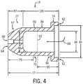
- FIGS. 3 and 4 illustrate additional embodiments of the plasma torch nozzle 19 shown in FIG. 2 .
- FIG. 3 illustrates a cross sectional view of an embodiment of the nozzle 19 having a non-tapered or non-angled edge 90 proximate to the second end 64 of the body 60. That is, in this embodiment, additional body mass is concentrated around the exit orifice 66 as compared to the embodiment of FIG. 2 .
- greater than or equal to approximately 50% of the overall mass of the nozzle body 60 is distributed between the second end 64 and the midpoint 73 of the body 60 with respect to the longitudinal length 72 of the nozzle body 60.
- the nozzle body 60 includes orifice portion 77 having orifice length 87 and a portion 94 having portion length 105, but does not include stepped portion 82.
- the body 60 includes only two inner diameters 84 and 86 instead of three inner diameters as in the embodiments of FIGS. 2 and 3 .
- portions 76 and 78 are a single portion 94.
- the average wall thickness of the orifice portion 77 may be divided by the inner diameter of the orifice portion 77 to give an orifice ratio of the average wall thickness to the inner diameter, and the orifice ratio may be greater than or equal to approximately 3.6.
- the electrode may be received by the stepped portion 82, in the embodiment of FIG. 4 an alternate receiving mechanism may be provided, and the electrode may rest, for example, within portion 94 of the body 60.
Landscapes
- Engineering & Computer Science (AREA)
- Physics & Mathematics (AREA)
- Plasma & Fusion (AREA)
- Spectroscopy & Molecular Physics (AREA)
- Mechanical Engineering (AREA)
- Geometry (AREA)
- Plasma Technology (AREA)
- Arc Welding In General (AREA)
Description
- This application claims priority to
U.S. Provisional Patent Application No. 61/467,448 - The invention relates generally to plasma cutting systems and, more particularly, to nozzles for a plasma torch for such systems.
- Many current industries rely on the manipulation of metals for building a variety of structures, such as buildings, bridges, cranes, vehicles, and so forth. Due to the strength and durability of many metals, a variety of systems have been developed that enable the manipulation of these materials. One such system is a plasma cutting system that creates plasma (from high temperature ionized gas) for the cutting of metal or other electrically conductive material. In general, in plasma cutting systems, an electrical arc converts a gas (e.g., compressed air) into plasma, which is sufficiently hot to melt a metal workpiece while the pressure of the gas blows away the molten metal. The electrical arc is typically initiated in a plasma torch, and gas flows through the torch. As such, a plasma torch is used to direct and control the plasma for cutting. Accordingly, the plasma torch typically includes a variety of components, such as plasma nozzles or tips that focus plasma gas into a constricted arc, that enable its direction and control. As the tip of the plasma torch is dragged across the workpiece, the hot plasma cuts the workpiece along that path of the torch tip. Since the plasma torch nozzles are typically utilized in this manner, the nozzles are often manufactured from metals, such as copper, that have high thermal and electrical conductivity. Unfortunately, during operation, current plasma torch nozzles are subject to considerable degradation and must be replaced throughout use, thus increasing the monetary cost and inefficiency of the plasma cutting process.
US 5,266,776 discloses a plasma arc cutting tip with a chamfer tip edge. -
US 5,880,426 discloses a water cooled nozzle tip. -
WO 2010/067306 discloses a cold plasma device with a tubular electrically conductive housing. - In one embodiment, a nozzle for a plasma torch includes a body having a first end, a second end having an exit orifice disposed therein, and a passageway extending from the first end to the second end. The passageway enables the flow of plasma gas from the first end, through the passageway, and to the exit orifice. Greater than or equal to approximately 50% of an overall mass of the body is distributed between the second end and a midpoint of the body with respect to a longitudinal length of the body.
- In another embodiment, a nozzle for a plasma torch includes a body having a first end and a second end having a plasma gas exit orifice disposed therein. A longitudinal distance from the first end to the center of mass of the body is greater than or equal to approximately 43% of a longitudinal length of the body.
- In another embodiment, a nozzle for a plasma torch includes a body having a first end and a second end having a plasma gas exit orifice disposed therein. A longitudinal distance from the first end to the center of mass of the body is greater than or equal to approximately 48% of a longitudinal length of the body.
- In another embodiment, a nozzle for a plasma torch includes a body having a first end, a second end having a plasma gas exit orifice disposed therein, a first portion extending from the first end along a longitudinal length of the body, an orifice portion extending from the second end along the longitudinal length of the body, and a middle portion disposed between the first portion and the orifice portion. An orifice ratio defined by an average wall thickness of the orifice portion divided by an inner diameter of the orifice portion is greater than or equal to approximately 3.6. A middle portion ratio defined by an average wall thickness of the middle portion divided by an inner diameter of the middle portion is greater than or equal to approximately 0.27.
- In another embodiment, a nozzle for a plasma torch includes a body having a first end, a second end having a plasma gas exit orifice disposed therein, an orifice portion extending from the second end along the longitudinal length of the body, and a second portion extending from the first end along a longitudinal length of the body to the orifice portion. An orifice ratio defined by an average wall thickness of the orifice portion divided by an inner diameter of the orifice portion is greater than or equal to approximately 3.5.
- In another embodiment, a plasma torch assembly includes a body and an electrode disposed within the body and adapted to receive power to enable generation of a plasma arc between the electrode and the workpiece. The assembly also includes a nozzle having a nozzle body having a first end and a second end having a plasma gas exit orifice disposed therein. A longitudinal distance from the first end to the center of mass of the nozzle body is greater than or equal to approximately 48% of a longitudinal length of the nozzle body, and an outer surface of the electrode and an inner annular wall of the nozzle define a plasma arc chamber.
- In another embodiment, a plasma cutting system includes a plasma torch having a nozzle having a body having a first end and a second end having a plasma gas exit orifice disposed therein. A longitudinal distance from the first end to the center of mass of the body is greater than or equal to approximately 48% of a longitudinal length of the body. The system also includes a power source adapted to couple to the plasma torch and to provide a current to the plasma torch for generating a pilot arc and for maintaining a plasma cutting arc.
- These and other features, aspects, and advantages of the present invention will become better understood when the following detailed description is read with reference to the accompanying drawings in which like characters represent like parts throughout the drawings, wherein:
-
FIG. 1 is a perspective view of a plasma cutting system in accordance with embodiments of the present invention; -
FIG. 2 is a cross sectional view of an embodiment of a plasma torch nozzle having an increased mass concentration proximate to an exit orifice of the nozzle in accordance with embodiments of the present invention; -
FIG. 3 is a cross sectional view of an embodiment of the plasma torch nozzle ofFIG. 2 having an untapered end portion in accordance with embodiments of the present invention; and -
FIG. 4 is a cross sectional view of an embodiment of the plasma torch nozzle ofFIG. 2 having an inner annular wall with a substantially constant diameter in accordance with embodiments of the present invention. - As described in more detail below, provided herein are embodiments of plasma torch nozzles having an increased concentration of mass proximate to the exit orifice of the nozzle. For example, in certain embodiments, the nozzle may include a body having greater than or equal to approximately 50% of the overall mass of the body distributed toward the exit orifice portion of the nozzle. The foregoing feature of presently disclosed embodiments may offer a variety of advantages over traditional systems that do not include an increased concentration of mass near the exit orifice. For example, presently contemplated embodiments may increase the local thermal capacity of the nozzle while reducing or eliminating the likelihood of overheating of the nozzle during operation. That is, during use in a plasma cutting operation, the face of the nozzle may be exposed to high temperatures arising from the plasma arc and blow back of molten material from the cut. By concentrating the mass of the body in the front portion of the nozzle about the exit orifice, presently disclosed embodiments of the nozzle may be more robust and resistant to wear from the arc and spatter than conventional designs.
- Referring now to the drawings,
FIG. 1 is a perspective view illustrating an embodiment of a portableplasma cutting system 10. The illustratedplasma cutting system 10 includes atorch power unit 12 coupled to aplasma torch 14 and aworkpiece clamp 16 via atorch cable 15 and aworkpiece cable 17, respectively. As described further below with respect toFIGS. 2-4 , theplasma torch 14 may include various features that provide improved performance and durability and longer usage life. For example, theplasma torch 14 may include anozzle 19 capable of focusing plasma gas into a constricted arc during a plasma cutting operation. Here again, it should be noted that by concentrating the mass of the plasma nozzle near the exit orifice (i.e., closer to the workpiece during operation), a variety of improvements may be realized as compared to conventional designs. - The
torch power unit 12 may be coupled to a power source (e.g., a power grid or a motor-driven generator) via apower cable 18. As described further below, the power source may provide a current to thetorch 14 for starting and generating a pilot arc, and for maintaining plasma and a cutting arc. For example, thepower unit 12 may be configured to supply a suitable voltage and current to create an electrical circuit from theunit 12, along thecable 15 to thetorch 14, across a gap between thetorch 14 and a work piece (e.g., as an electrical arc), through the work piece to theclamp 16, through thecable 17 back to theunit 12. - In the illustrated embodiment, the
power unit 12 includes anenclosure 20 defining a generally closed volume to support various circuits, sensor features, control features, and gas supply features (e.g., air compressor). For example, thesystem 10 may include sensors and controls to adjust thepower unit 10 to account for various conditions, e.g., altitude, temperature, pressure, and so forth. The illustratedsystem 10 also may include ahandle 22 on the top side of theenclosure 20 to enable easier transportation of thesystem 10. The illustratedsystem 10 also may include alatching mechanism 24 that may secure thetorch 14, thecable 17, theclamp 16, and/or thepower cable 18. Theenclosure 20 may also includevents 28 to relieve heat and/or pressure inside thesystem 10. It should be noted that in other embodiments, additional vents may be located on other panels of theenclosure 20. - In the illustrated
system 10, acontrol panel 38 is included at an end of thepower unit 12. Thecontrol panel 38 may include various control inputs, indicators, displays, electrical outputs, air outputs, and so forth. In an embodiment, auser input 40 may include a button, knob, or switch configured to enable selection of a mode of operation (e.g., plasma cut, gouge, etc.), power on/off, an output current level, gas (e.g., air) flow rate, gas (e.g., air) pressure, gas type, a work piece type, a control type (e.g., manual or automatic feedback control), or a combination thereof. The control panel 34 may also includevarious indicators 42 to provide feedback to the user. For example, theindicators 42 may include one or more light emitting diodes (LED) and/or liquid crystal displays (LCD) to display on/off status, current level, voltage level, gas (e.g., air) pressure, gas (e.g., air) flow, environmental conditions (e.g., altitude, temperature, pressure, etc.), or any other parameter. Additionally, theindicators 42 may include an LED or LCD that displays a trouble or warning indicator if there is a problem with thesystem 10. Embodiments of thecontrol panel 38 may include any number inputs and outputs, such as welding methods, air compressor settings, oil pressure, oil temperature, and system power. - Further, the
user inputs 40 andindicators 42 may be electrically coupled to control circuitry and enable a user to set and monitor various parameters of thesystem 10. For example, theindicators 42 may display environmental conditions (e.g., altitude, temperature, pressure, etc.) that prompt a user to manually adjust the current, voltage, gas flow rate, gas pressure, or other operational parameters, or a combination thereof. - The
plasma torch 14 includes ahandle 44 and atrigger 46 with a guard, as well as thenozzle 19, which may conform to a variety of implementation-specific features, as described below with respect toFIGS. 2-4 . Theclamp 16 includes an electrically conductivematerial clamping portion 48 having insulated handles 50. Thepower cable 18 includes aplug 52 for connection to a power source such as a wall socket or a motor-driven generator. Theplug 52 may be configured to work with a variety of sockets or outlets, and thesystem 10 may receive different power sources, such asAC 50/60 Hz, 400 Hz, single or three phase 120V, 230V, 400V, 460V, 575V, any voltage in between such voltages, voltages exceeding the upper limit voltage, voltages below the lower limit voltage, and so forth. - It should be noted that the illustrated
plasma cutting system 10 is merely an example, and in other embodiments, thesystem 10 is subject to a variety of implementation-specific modifications, as would be understood by one skilled in the art. For example, In some embodiments, thepower unit 12 may be configured as a stationary, rather than a portable, unit. Additionally, thecontrol panel 38 may include fewer or additional buttons, knobs, and so forth, as dictated by the demands of the given application. Indeed, it is presently contemplated that the plasma torch nozzles shown and described herein may be utilized with any plasma cutting torch associated with any plasma cutting system. -
FIG. 2 is a cross sectional view of an embodiment of theplasma torch nozzle 19 having an improved mass distribution in accordance with a presently disclosed embodiment. As illustrated, thenozzle 19 includes abody 60 having afirst end 62 and asecond end 64. As shown, anexit orifice 66 is disposed in thesecond end 64 of thebody 60, which has a taperededge 67. Aninternal passageway 68 extends from thefirst end 62 to thesecond end 64. In the illustrated embodiment, an innerannular wall 70 of thenozzle 19 defines a series of portions along alongitudinal length 72 of thebody 60 having amidpoint 73 defined bymidpoint length 75. - Specifically, the illustrated
body 60 includes aportion 74 proximate to thefirst end 62 and included in afirst end portion 78, amiddle portion 76, and anorifice portion 77 proximate to thesecond end 64. A length of theorifice portion 77 is defined byorifice portion length 87, a length of themiddle portion 76 is defined bymiddle portion length 89, and a length of thefirst end portion 78 is defined by firstend portion length 91. Further, a substantially perpendicularannular step 80 is included in thefirst end portion 78 while a recessed annular orangled step 82 is provided in themiddle portion 76. As such, in the illustrated embodiment, the foregoing structure defines a firstinner diameter 84, a secondinner diameter 86, and a thirdinner diameter 88 of thebody 60. - As noted above, in certain embodiments, the provided
plasma torch nozzle 19 may include one or more features resulting in an increased concentration of mass proximate to theexit orifice 66 of thenozzle body 60 and, thus, improving the robustness and resistivity to heat of thenozzle 19 during use in a plasma cutting operation. Specifically, in one embodiment, a ratio of the average wall thickness to the inner diameter of certain portions of thebody 60 may be improved compared to conventional designs. More specifically, an average wall thickness of theorifice portion 77 may be given by the cross sectional area indicated by hatched portion 97 inFIG. 2 divided by theorifice length 87. This average wall thickness of theorifice portion 77 may then be divided by the inner diameter of theorifice portion 77 to give an orifice ratio of the average wall thickness to the inner diameter. In one embodiment, the orifice ratio may be greater than or equal to approximately 3.25. In another embodiment, the orifice ratio may be greater than or equal to approximately 3.6. Still further, in other embodiments, the orifice ratio may be greater than or equal to between approximately 3.25 and approximately 4. - Similarly, the average wall thickness of the
middle portion 76 may be given by the cross sectional area indicated by hatchedportion 99 inFIG. 2 divided by themiddle portion length 89. This average wall thickness of themiddle portion 76 may then be divided by the inner diameter of themiddle portion 76 to give a middle portion ratio of the average wall thickness to the inner diameter. In one embodiment, the middle portion ratio may be greater than or equal to approximately 0.25. In another embodiment, the orifice ratio may be greater than or equal to approximately 0.27. - As indicated by dashed
line 93 inFIG. 2 , thenozzle 19 includes a center of mass that lies at the center ofmass location 93 along thelength 72 of thenozzle body 60. Accordingly, a center ofmass distance 95 is defined from thefirst end 62 of thebody 60 to the center ofmass 93 of thebody 60. In certain embodiments, the center ofmass 93 may lie at or near thelongitudinal midpoint 73. For example, in one embodiment, the center ofmass distance 95 may be greater than or equal to approximately 43% of thebody length 72. In another embodiment, the center ofmass distance 95 may be greater than or equal to approximately 48% of thebody length 72. Still further, in other embodiments, the center ofmass distance 95 may be greater than or equal to between approximately 45% and approximately 55% of thebody length 72. By shifting the center ofmass 93 toward thefirst end 62 rather than thesecond end 64, presently disclosed embodiments may increase the local thermal capacity of the nozzle around theexit orifice 66 while reducing or eliminating the likelihood of overheating of thenozzle 19 during operation. That is, by concentrating the mass of the body in the front portion of thenozzle body 60 and about theexit orifice 66, presently disclosed embodiments of thenozzle 19 may be more robust and resistant to wear from the arc and spatter than conventional designs. - In some embodiments, greater than or equal to approximately 50% of the overall mass of the
nozzle body 60 is distributed between thesecond end 64 and themidpoint 73 of thebody 60 with respect to thelongitudinal length 72 of thenozzle body 60. As such, in these embodiments, the thickness of the material surrounding theexit orifice 66 may be increased as compared to traditional nozzles. As mentioned above, the foregoing feature may offer a variety of advantages both during normal plasma cutting events as well as during transient events in which thenozzle 19 may be utilized as a heat sink. For example, during the pilot arc, thenozzle 19 may function as a temporary anode to which the arc attaches in order to complete the secondary circuit. Since the anode bears much of the heat from the arc during the cutting process, having greater than 50% of the mass of the body distributed near thesecond end 64 of thenozzle 19 where the pilot arc attaches may improve the lifespan of thenozzle 19. - Further, during reverse transfer events, when the
nozzle 19 may come into circuit to become the temporary anode, thepower supply 14 will reduce the output current to pilot current levels to reduce or prevent the likelihood that damage will occur to thenozzle 19. However, in certain instances, the power supply may not change from cut current to pilot current quickly enough, and thenozzle 19 may therefore have to conduct a quantity greater than the pilot current for a period of time. In such instances, the concentration of the mass of thebody 60 near thesecond end 64 may enable better absorption and dissipation of the heat generated during these transient over current events that typically occur during reverse transfer events. - Presently contemplated embodiments of the
plasma torch nozzles 19 may be made of a variety of types of suitable materials. For example, thenozzle 19 may be partially or fully formed from metallic materials, such as copper, or any other desired electrically conductive material. Still further, embodiments of thenozzles 19 described herein may be disposable rather than reusable and, as such, may be configured as consumable components of the plasma torch assembly. -
FIGS. 3 and4 illustrate additional embodiments of theplasma torch nozzle 19 shown inFIG. 2 . Specifically,FIG. 3 illustrates a cross sectional view of an embodiment of thenozzle 19 having a non-tapered ornon-angled edge 90 proximate to thesecond end 64 of thebody 60. That is, in this embodiment, additional body mass is concentrated around theexit orifice 66 as compared to the embodiment ofFIG. 2 . Here again, greater than or equal to approximately 50% of the overall mass of thenozzle body 60 is distributed between thesecond end 64 and themidpoint 73 of thebody 60 with respect to thelongitudinal length 72 of thenozzle body 60. - In the embodiment illustrated in
FIG. 4 , thenozzle body 60 includesorifice portion 77 havingorifice length 87 and aportion 94 havingportion length 105, but does not include steppedportion 82. As such, in this embodiment, thebody 60 includes only twoinner diameters FIGS. 2 and 3 . As illustrated, in this embodiment,portions single portion 94. Here again, the average wall thickness of theorifice portion 77 may be divided by the inner diameter of theorifice portion 77 to give an orifice ratio of the average wall thickness to the inner diameter, and the orifice ratio may be greater than or equal to approximately 3.6. It should be noted that while in the embodiments ofFIGS. 2 and 3 , the electrode may be received by the steppedportion 82, in the embodiment ofFIG. 4 an alternate receiving mechanism may be provided, and the electrode may rest, for example, withinportion 94 of thebody 60. - The invention is defined by the appended claims.
Claims (12)
- A nozzle (19) for a plasma cutting torch (14), comprising:a body (60) comprising a first end (62), a second end (64) having a plasma gas exit orifice (66) disposed therein, a first end portion (78) extending from the first end (62) along the longitudinal length of the body (60), an orifice portion (77) extending from the second end (64) along the longitudinal length of the body, and a middle portion (76) disposed between the first end portion (78) and the orifice portion (77); and a perpendicular annular step (80) is included in the first end portion (78) characterized in that an orifice ratio defined by an average wall thickness of the orifice portion (77) divided by an inner diameter of the orifice portion is greater than or equal to approximately 3.6, and a middle portion ratio defined by an average wall thickness of the middle portion (76) divided by an inner diameter of the middle portion is greater than or equal to approximately 0.27, and that a recessed inner angled step (82) is provided in the middle portion (76).
- The nozzle of claim 1, wherein the orifice portion (77) comprises an annular tapered edge (67).
- The nozzle of claim 1 wherein a longitudinal distance (95) from the first end (62) to a center of mass (93) of the body (60) is greater than or equal to approximately 48% of the longitudinal length (72) of the body.
- The nozzle of claim 1, wherein a passageway (68) extends from the first end (62) to the second end (64) and is configured to enable the flow of plasma gas from the first end (62), through the passageway (68), and to the exit orifice (66); and
wherein greater than or equal to approximately 50% of an overall mass of the body (60) is distributed between the second end (64) and the midpoint (73) of the body with respect to the longitudinal length (72) of the body. - The nozzle of claim 4, wherein the body (60) comprises a metallic material.
- The nozzle of claim 5, wherein the metallic material comprises copper.
- The nozzle of one of claims 4 to 6, wherein the passageway (68) in the first end portion (78) has a first inner diameter (84) and a second inner diameter (86) less than the first inner diameter, and wherein the first end portion (78) and the middle portion (76) are connected via the recessed inner angled step (82), such that the middle portion (76) has a third inner diameter (88) less than the second inner diameter (86).
- The nozzle of claim 4, wherein the body (60) comprises an annular inner wall (70) having a stepped profile diameter.
- The nozzle of claim 4, wherein greater than or equal to approximately 25% of the overall mass of the body (60) is distributed throughout the orifice portion (77).
- A plasma torch assembly, comprising:a nozzle (19) according to one of the preceding claims; and an electrode disposed within the body (60) and configured to receive power to enable generation of a plasma arc between the electrode and the workpiece.
- A plasma cutting system (10), comprising :a plasma torch (14) comprising a nozzle (19) according to one of claims 1 to 9, anda power source (12) configured to couple to the plasma torch (14) and to provide a current to the plasma torch (14) for generating a pilot arc and for maintaining a plasma cutting arc.
- The system of claim 11, wherein the plasma torch (14) comprises an electrode disposed within the body (60) of the nozzle (19), and wherein an outer surface of the electrode and an inner annular wall of the nozzle define a plasma arc chamber.
Applications Claiming Priority (2)
| Application Number | Priority Date | Filing Date | Title |
|---|---|---|---|
| US201161467448P | 2011-03-25 | 2011-03-25 | |
| PCT/US2012/030431 WO2012135061A1 (en) | 2011-03-25 | 2012-03-23 | Plasma torch systems having improved plasma nozzles |
Publications (2)
| Publication Number | Publication Date |
|---|---|
| EP2689641A1 EP2689641A1 (en) | 2014-01-29 |
| EP2689641B1 true EP2689641B1 (en) | 2017-05-03 |
Family
ID=45932536
Family Applications (1)
| Application Number | Title | Priority Date | Filing Date |
|---|---|---|---|
| EP12712832.0A Revoked EP2689641B1 (en) | 2011-03-25 | 2012-03-23 | Plasma torch systems having improved plasma nozzles |
Country Status (8)
| Country | Link |
|---|---|
| US (1) | US11160156B2 (en) |
| EP (1) | EP2689641B1 (en) |
| CN (2) | CN103563491A (en) |
| AU (1) | AU2012236904B2 (en) |
| BR (1) | BR112013024639A2 (en) |
| CA (1) | CA2831285C (en) |
| MX (1) | MX356075B (en) |
| WO (1) | WO2012135061A1 (en) |
Families Citing this family (3)
| Publication number | Priority date | Publication date | Assignee | Title |
|---|---|---|---|---|
| US9144148B2 (en) | 2013-07-25 | 2015-09-22 | Hypertherm, Inc. | Devices for gas cooling plasma arc torches and related systems and methods |
| CN110291846A (en) * | 2016-12-05 | 2019-09-27 | 海别得公司 | Asymmetric Consumables for Plasma Arc Torches |
| DE102021120826A1 (en) * | 2021-08-10 | 2023-02-16 | Muegge Gmbh | Process for generating a plasma flame and plasma generating device |
Citations (4)
| Publication number | Priority date | Publication date | Assignee | Title |
|---|---|---|---|---|
| US5266776A (en) | 1992-08-10 | 1993-11-30 | Thermal Dynamics Corporation | Plasma arc cutting and welding tip |
| US5880426A (en) | 1996-08-28 | 1999-03-09 | Doryokuro Kakunenryo Kaihatsu Jigyodan | Indirectly-cooled plasma jet torch |
| US5893985A (en) | 1997-03-14 | 1999-04-13 | The Lincoln Electric Company | Plasma arc torch |
| WO2010067306A2 (en) | 2008-12-09 | 2010-06-17 | Advanced Machines Sàrl | Device and method for generating a plasma flow |
Family Cites Families (14)
| Publication number | Priority date | Publication date | Assignee | Title |
|---|---|---|---|---|
| US3115747A (en) * | 1959-12-15 | 1963-12-31 | Inca Engineering Corp | Apparatus for converting fluid energy from potential to kinetic |
| JP2573011B2 (en) * | 1988-01-25 | 1997-01-16 | 津田駒工業株式会社 | Method of manufacturing a nozzle member for conveying yarn in a textile machine |
| JP2516804B2 (en) * | 1988-12-26 | 1996-07-24 | 株式会社小松製作所 | Plasma torch |
| US5705785A (en) * | 1994-12-30 | 1998-01-06 | Plasma-Laser Technologies Ltd | Combined laser and plasma arc welding torch |
| FR2735710B1 (en) * | 1995-06-23 | 1997-07-25 | Soudure Autogene Francaise | PLASMA TORCH HEAD AND PLASMA TORCH COMPRISING THE SAME |
| CN2276240Y (en) * | 1996-12-04 | 1998-03-11 | 西安交通大学 | Internal powder conveying combined spray nozzle for plasma arc powder spray welding gun |
| US6897402B2 (en) * | 2002-04-24 | 2005-05-24 | Thermal Spray Technologies, Inc. | Plasma-arc spray anode and gun body |
| US6963045B2 (en) * | 2003-11-14 | 2005-11-08 | Tatras, Inc. | Plasma arc cutting torch nozzle |
| FR2863817A1 (en) * | 2003-12-12 | 2005-06-17 | Air Liquide | TUYERE WITH DEFLECTOR FOR PLASMA ARC TORCH |
| US7737383B2 (en) * | 2006-08-25 | 2010-06-15 | Thermal Dynamics Corporation | Contoured shield orifice for a plasma arc torch |
| ES2534215T3 (en) | 2006-08-30 | 2015-04-20 | Oerlikon Metco Ag, Wohlen | Plasma spray device and a method for introducing a liquid precursor into a plasma gas system |
| EP2022299B1 (en) * | 2007-02-16 | 2014-04-30 | Hypertherm, Inc | Gas-cooled plasma arc cutting torch |
| US8222561B2 (en) | 2007-09-04 | 2012-07-17 | Thermal Dynamics Corporation | Drag tip for a plasma cutting torch |
| CN201669503U (en) * | 2010-06-12 | 2010-12-15 | 济南尼克焊接技术有限公司 | Plasma cutter with electrode and nozzle |
-
2012
- 2012-03-23 BR BR112013024639A patent/BR112013024639A2/en not_active IP Right Cessation
- 2012-03-23 MX MX2013010979A patent/MX356075B/en active IP Right Grant
- 2012-03-23 WO PCT/US2012/030431 patent/WO2012135061A1/en not_active Ceased
- 2012-03-23 CA CA2831285A patent/CA2831285C/en not_active Expired - Fee Related
- 2012-03-23 CN CN201280025321.6A patent/CN103563491A/en active Pending
- 2012-03-23 US US13/428,958 patent/US11160156B2/en active Active
- 2012-03-23 AU AU2012236904A patent/AU2012236904B2/en not_active Ceased
- 2012-03-23 CN CN201910074209.5A patent/CN110087381A/en active Pending
- 2012-03-23 EP EP12712832.0A patent/EP2689641B1/en not_active Revoked
Patent Citations (4)
| Publication number | Priority date | Publication date | Assignee | Title |
|---|---|---|---|---|
| US5266776A (en) | 1992-08-10 | 1993-11-30 | Thermal Dynamics Corporation | Plasma arc cutting and welding tip |
| US5880426A (en) | 1996-08-28 | 1999-03-09 | Doryokuro Kakunenryo Kaihatsu Jigyodan | Indirectly-cooled plasma jet torch |
| US5893985A (en) | 1997-03-14 | 1999-04-13 | The Lincoln Electric Company | Plasma arc torch |
| WO2010067306A2 (en) | 2008-12-09 | 2010-06-17 | Advanced Machines Sàrl | Device and method for generating a plasma flow |
Non-Patent Citations (2)
| Title |
|---|
| "HiFocus - Plasmaschneiden ein neues Qualitätsniveau in der Fertigung", KJELLBERG FINSTERWALDE, 2 June 2003 (2003-06-02), pages 1 - 7, XP055462127 |
| "Plasmaschneidanlage HiFocus 160i das Multitalent zum Markieren und Schneiden von 0,5 bis 50 mm für höchste Produktivität", KJELLBERG FINSTERWALDE, 2009, pages 1 - 6, XP055462131 |
Also Published As
| Publication number | Publication date |
|---|---|
| CA2831285C (en) | 2018-08-14 |
| EP2689641A1 (en) | 2014-01-29 |
| CN103563491A (en) | 2014-02-05 |
| MX2013010979A (en) | 2014-04-30 |
| BR112013024639A2 (en) | 2016-12-13 |
| US11160156B2 (en) | 2021-10-26 |
| AU2012236904B2 (en) | 2015-09-17 |
| US20120241418A1 (en) | 2012-09-27 |
| CN110087381A (en) | 2019-08-02 |
| WO2012135061A1 (en) | 2012-10-04 |
| CA2831285A1 (en) | 2012-10-04 |
| AU2012236904A1 (en) | 2013-11-07 |
| MX356075B (en) | 2018-05-14 |
Similar Documents
| Publication | Publication Date | Title |
|---|---|---|
| EP2745651B1 (en) | Plasma torch and retaining cap with fast securing threads | |
| EP2745652B1 (en) | Plasma torch and components | |
| US8395074B2 (en) | Plasma ARC systems with cutting and marking functions | |
| CN103828489A (en) | Plasma spray gun with ergonomic gun handle | |
| US6852943B2 (en) | Strain relief mechanism for a plasma arc torch | |
| EP2689641B1 (en) | Plasma torch systems having improved plasma nozzles | |
| US7297900B2 (en) | Bypass weld torch |
Legal Events
| Date | Code | Title | Description |
|---|---|---|---|
| PUAI | Public reference made under article 153(3) epc to a published international application that has entered the european phase |
Free format text: ORIGINAL CODE: 0009012 |
|
| 17P | Request for examination filed |
Effective date: 20131017 |
|
| AK | Designated contracting states |
Kind code of ref document: A1 Designated state(s): AL AT BE BG CH CY CZ DE DK EE ES FI FR GB GR HR HU IE IS IT LI LT LU LV MC MK MT NL NO PL PT RO RS SE SI SK SM TR |
|
| RAP1 | Party data changed (applicant data changed or rights of an application transferred) |
Owner name: ILLINOIS TOOL WORKS INC. |
|
| DAX | Request for extension of the european patent (deleted) | ||
| 17Q | First examination report despatched |
Effective date: 20151214 |
|
| GRAP | Despatch of communication of intention to grant a patent |
Free format text: ORIGINAL CODE: EPIDOSNIGR1 |
|
| STAA | Information on the status of an ep patent application or granted ep patent |
Free format text: STATUS: GRANT OF PATENT IS INTENDED |
|
| INTG | Intention to grant announced |
Effective date: 20161221 |
|
| GRAS | Grant fee paid |
Free format text: ORIGINAL CODE: EPIDOSNIGR3 |
|
| GRAA | (expected) grant |
Free format text: ORIGINAL CODE: 0009210 |
|
| STAA | Information on the status of an ep patent application or granted ep patent |
Free format text: STATUS: THE PATENT HAS BEEN GRANTED |
|
| AK | Designated contracting states |
Kind code of ref document: B1 Designated state(s): AL AT BE BG CH CY CZ DE DK EE ES FI FR GB GR HR HU IE IS IT LI LT LU LV MC MK MT NL NO PL PT RO RS SE SI SK SM TR |
|
| REG | Reference to a national code |
Ref country code: GB Ref legal event code: FG4D |
|
| REG | Reference to a national code |
Ref country code: AT Ref legal event code: REF Ref document number: 891292 Country of ref document: AT Kind code of ref document: T Effective date: 20170515 Ref country code: CH Ref legal event code: EP |
|
| REG | Reference to a national code |
Ref country code: IE Ref legal event code: FG4D |
|
| REG | Reference to a national code |
Ref country code: DE Ref legal event code: R096 Ref document number: 602012031899 Country of ref document: DE |
|
| REG | Reference to a national code |
Ref country code: NL Ref legal event code: MP Effective date: 20170503 |
|
| REG | Reference to a national code |
Ref country code: AT Ref legal event code: MK05 Ref document number: 891292 Country of ref document: AT Kind code of ref document: T Effective date: 20170503 |
|
| REG | Reference to a national code |
Ref country code: LT Ref legal event code: MG4D |
|
| PG25 | Lapsed in a contracting state [announced via postgrant information from national office to epo] |
Ref country code: AT Free format text: LAPSE BECAUSE OF FAILURE TO SUBMIT A TRANSLATION OF THE DESCRIPTION OR TO PAY THE FEE WITHIN THE PRESCRIBED TIME-LIMIT Effective date: 20170503 Ref country code: HR Free format text: LAPSE BECAUSE OF FAILURE TO SUBMIT A TRANSLATION OF THE DESCRIPTION OR TO PAY THE FEE WITHIN THE PRESCRIBED TIME-LIMIT Effective date: 20170503 Ref country code: NO Free format text: LAPSE BECAUSE OF FAILURE TO SUBMIT A TRANSLATION OF THE DESCRIPTION OR TO PAY THE FEE WITHIN THE PRESCRIBED TIME-LIMIT Effective date: 20170803 Ref country code: FI Free format text: LAPSE BECAUSE OF FAILURE TO SUBMIT A TRANSLATION OF THE DESCRIPTION OR TO PAY THE FEE WITHIN THE PRESCRIBED TIME-LIMIT Effective date: 20170503 Ref country code: LT Free format text: LAPSE BECAUSE OF FAILURE TO SUBMIT A TRANSLATION OF THE DESCRIPTION OR TO PAY THE FEE WITHIN THE PRESCRIBED TIME-LIMIT Effective date: 20170503 Ref country code: GR Free format text: LAPSE BECAUSE OF FAILURE TO SUBMIT A TRANSLATION OF THE DESCRIPTION OR TO PAY THE FEE WITHIN THE PRESCRIBED TIME-LIMIT Effective date: 20170804 Ref country code: ES Free format text: LAPSE BECAUSE OF FAILURE TO SUBMIT A TRANSLATION OF THE DESCRIPTION OR TO PAY THE FEE WITHIN THE PRESCRIBED TIME-LIMIT Effective date: 20170503 |
|
| PG25 | Lapsed in a contracting state [announced via postgrant information from national office to epo] |
Ref country code: LV Free format text: LAPSE BECAUSE OF FAILURE TO SUBMIT A TRANSLATION OF THE DESCRIPTION OR TO PAY THE FEE WITHIN THE PRESCRIBED TIME-LIMIT Effective date: 20170503 Ref country code: PL Free format text: LAPSE BECAUSE OF FAILURE TO SUBMIT A TRANSLATION OF THE DESCRIPTION OR TO PAY THE FEE WITHIN THE PRESCRIBED TIME-LIMIT Effective date: 20170503 Ref country code: SE Free format text: LAPSE BECAUSE OF FAILURE TO SUBMIT A TRANSLATION OF THE DESCRIPTION OR TO PAY THE FEE WITHIN THE PRESCRIBED TIME-LIMIT Effective date: 20170503 Ref country code: IS Free format text: LAPSE BECAUSE OF FAILURE TO SUBMIT A TRANSLATION OF THE DESCRIPTION OR TO PAY THE FEE WITHIN THE PRESCRIBED TIME-LIMIT Effective date: 20170903 Ref country code: RS Free format text: LAPSE BECAUSE OF FAILURE TO SUBMIT A TRANSLATION OF THE DESCRIPTION OR TO PAY THE FEE WITHIN THE PRESCRIBED TIME-LIMIT Effective date: 20170503 Ref country code: BG Free format text: LAPSE BECAUSE OF FAILURE TO SUBMIT A TRANSLATION OF THE DESCRIPTION OR TO PAY THE FEE WITHIN THE PRESCRIBED TIME-LIMIT Effective date: 20170803 Ref country code: NL Free format text: LAPSE BECAUSE OF FAILURE TO SUBMIT A TRANSLATION OF THE DESCRIPTION OR TO PAY THE FEE WITHIN THE PRESCRIBED TIME-LIMIT Effective date: 20170503 |
|
| PG25 | Lapsed in a contracting state [announced via postgrant information from national office to epo] |
Ref country code: RO Free format text: LAPSE BECAUSE OF FAILURE TO SUBMIT A TRANSLATION OF THE DESCRIPTION OR TO PAY THE FEE WITHIN THE PRESCRIBED TIME-LIMIT Effective date: 20170503 Ref country code: DK Free format text: LAPSE BECAUSE OF FAILURE TO SUBMIT A TRANSLATION OF THE DESCRIPTION OR TO PAY THE FEE WITHIN THE PRESCRIBED TIME-LIMIT Effective date: 20170503 Ref country code: EE Free format text: LAPSE BECAUSE OF FAILURE TO SUBMIT A TRANSLATION OF THE DESCRIPTION OR TO PAY THE FEE WITHIN THE PRESCRIBED TIME-LIMIT Effective date: 20170503 Ref country code: SK Free format text: LAPSE BECAUSE OF FAILURE TO SUBMIT A TRANSLATION OF THE DESCRIPTION OR TO PAY THE FEE WITHIN THE PRESCRIBED TIME-LIMIT Effective date: 20170503 Ref country code: CZ Free format text: LAPSE BECAUSE OF FAILURE TO SUBMIT A TRANSLATION OF THE DESCRIPTION OR TO PAY THE FEE WITHIN THE PRESCRIBED TIME-LIMIT Effective date: 20170503 |
|
| REG | Reference to a national code |
Ref country code: DE Ref legal event code: R026 Ref document number: 602012031899 Country of ref document: DE |
|
| PLBI | Opposition filed |
Free format text: ORIGINAL CODE: 0009260 |
|
| PLAX | Notice of opposition and request to file observation + time limit sent |
Free format text: ORIGINAL CODE: EPIDOSNOBS2 |
|
| PG25 | Lapsed in a contracting state [announced via postgrant information from national office to epo] |
Ref country code: SM Free format text: LAPSE BECAUSE OF FAILURE TO SUBMIT A TRANSLATION OF THE DESCRIPTION OR TO PAY THE FEE WITHIN THE PRESCRIBED TIME-LIMIT Effective date: 20170503 |
|
| 26 | Opposition filed |
Opponent name: KJELLBERG FINSTERWALDE PLASMA UND MASCHINEN GMBH Effective date: 20180202 |
|
| REG | Reference to a national code |
Ref country code: FR Ref legal event code: PLFP Year of fee payment: 7 |
|
| PG25 | Lapsed in a contracting state [announced via postgrant information from national office to epo] |
Ref country code: SI Free format text: LAPSE BECAUSE OF FAILURE TO SUBMIT A TRANSLATION OF THE DESCRIPTION OR TO PAY THE FEE WITHIN THE PRESCRIBED TIME-LIMIT Effective date: 20170503 |
|
| PLBB | Reply of patent proprietor to notice(s) of opposition received |
Free format text: ORIGINAL CODE: EPIDOSNOBS3 |
|
| REG | Reference to a national code |
Ref country code: CH Ref legal event code: PL |
|
| PG25 | Lapsed in a contracting state [announced via postgrant information from national office to epo] |
Ref country code: MC Free format text: LAPSE BECAUSE OF FAILURE TO SUBMIT A TRANSLATION OF THE DESCRIPTION OR TO PAY THE FEE WITHIN THE PRESCRIBED TIME-LIMIT Effective date: 20170503 |
|
| REG | Reference to a national code |
Ref country code: BE Ref legal event code: MM Effective date: 20180331 |
|
| REG | Reference to a national code |
Ref country code: IE Ref legal event code: MM4A |
|
| PG25 | Lapsed in a contracting state [announced via postgrant information from national office to epo] |
Ref country code: LU Free format text: LAPSE BECAUSE OF NON-PAYMENT OF DUE FEES Effective date: 20180323 |
|
| PG25 | Lapsed in a contracting state [announced via postgrant information from national office to epo] |
Ref country code: IE Free format text: LAPSE BECAUSE OF NON-PAYMENT OF DUE FEES Effective date: 20180323 |
|
| PG25 | Lapsed in a contracting state [announced via postgrant information from national office to epo] |
Ref country code: BE Free format text: LAPSE BECAUSE OF NON-PAYMENT OF DUE FEES Effective date: 20180331 Ref country code: CH Free format text: LAPSE BECAUSE OF NON-PAYMENT OF DUE FEES Effective date: 20180331 Ref country code: LI Free format text: LAPSE BECAUSE OF NON-PAYMENT OF DUE FEES Effective date: 20180331 |
|
| PG25 | Lapsed in a contracting state [announced via postgrant information from national office to epo] |
Ref country code: MT Free format text: LAPSE BECAUSE OF NON-PAYMENT OF DUE FEES Effective date: 20180323 |
|
| PG25 | Lapsed in a contracting state [announced via postgrant information from national office to epo] |
Ref country code: TR Free format text: LAPSE BECAUSE OF FAILURE TO SUBMIT A TRANSLATION OF THE DESCRIPTION OR TO PAY THE FEE WITHIN THE PRESCRIBED TIME-LIMIT Effective date: 20170503 |
|
| PG25 | Lapsed in a contracting state [announced via postgrant information from national office to epo] |
Ref country code: HU Free format text: LAPSE BECAUSE OF FAILURE TO SUBMIT A TRANSLATION OF THE DESCRIPTION OR TO PAY THE FEE WITHIN THE PRESCRIBED TIME-LIMIT; INVALID AB INITIO Effective date: 20120323 Ref country code: PT Free format text: LAPSE BECAUSE OF FAILURE TO SUBMIT A TRANSLATION OF THE DESCRIPTION OR TO PAY THE FEE WITHIN THE PRESCRIBED TIME-LIMIT Effective date: 20170503 |
|
| PG25 | Lapsed in a contracting state [announced via postgrant information from national office to epo] |
Ref country code: MK Free format text: LAPSE BECAUSE OF NON-PAYMENT OF DUE FEES Effective date: 20170503 Ref country code: CY Free format text: LAPSE BECAUSE OF FAILURE TO SUBMIT A TRANSLATION OF THE DESCRIPTION OR TO PAY THE FEE WITHIN THE PRESCRIBED TIME-LIMIT Effective date: 20170503 |
|
| PG25 | Lapsed in a contracting state [announced via postgrant information from national office to epo] |
Ref country code: AL Free format text: LAPSE BECAUSE OF FAILURE TO SUBMIT A TRANSLATION OF THE DESCRIPTION OR TO PAY THE FEE WITHIN THE PRESCRIBED TIME-LIMIT Effective date: 20170503 |
|
| PGFP | Annual fee paid to national office [announced via postgrant information from national office to epo] |
Ref country code: FR Payment date: 20210325 Year of fee payment: 10 |
|
| PGFP | Annual fee paid to national office [announced via postgrant information from national office to epo] |
Ref country code: GB Payment date: 20210329 Year of fee payment: 10 |
|
| RDAF | Communication despatched that patent is revoked |
Free format text: ORIGINAL CODE: EPIDOSNREV1 |
|
| PLAB | Opposition data, opponent's data or that of the opponent's representative modified |
Free format text: ORIGINAL CODE: 0009299OPPO |
|
| GBPC | Gb: european patent ceased through non-payment of renewal fee |
Effective date: 20220323 |
|
| R26 | Opposition filed (corrected) |
Opponent name: KJELLBERG FINSTERWALDE PLASMA UND MASCHINEN GMBH Effective date: 20180202 |
|
| APBM | Appeal reference recorded |
Free format text: ORIGINAL CODE: EPIDOSNREFNO |
|
| APBP | Date of receipt of notice of appeal recorded |
Free format text: ORIGINAL CODE: EPIDOSNNOA2O |
|
| APAH | Appeal reference modified |
Free format text: ORIGINAL CODE: EPIDOSCREFNO |
|
| PG25 | Lapsed in a contracting state [announced via postgrant information from national office to epo] |
Ref country code: GB Free format text: LAPSE BECAUSE OF NON-PAYMENT OF DUE FEES Effective date: 20220323 Ref country code: FR Free format text: LAPSE BECAUSE OF NON-PAYMENT OF DUE FEES Effective date: 20220331 |
|
| APBQ | Date of receipt of statement of grounds of appeal recorded |
Free format text: ORIGINAL CODE: EPIDOSNNOA3O |
|
| P01 | Opt-out of the competence of the unified patent court (upc) registered |
Effective date: 20230606 |
|
| PGFP | Annual fee paid to national office [announced via postgrant information from national office to epo] |
Ref country code: DE Payment date: 20240327 Year of fee payment: 13 |
|
| REG | Reference to a national code |
Ref country code: DE Ref legal event code: R103 Ref document number: 602012031899 Country of ref document: DE Ref country code: DE Ref legal event code: R064 Ref document number: 602012031899 Country of ref document: DE |
|
| APBU | Appeal procedure closed |
Free format text: ORIGINAL CODE: EPIDOSNNOA9O |
|
| RDAG | Patent revoked |
Free format text: ORIGINAL CODE: 0009271 |
|
| STAA | Information on the status of an ep patent application or granted ep patent |
Free format text: STATUS: PATENT REVOKED |
|
| REG | Reference to a national code |
Ref country code: CH Ref legal event code: PL |
|
| 27W | Patent revoked |
Effective date: 20250213 |
|
| PGFP | Annual fee paid to national office [announced via postgrant information from national office to epo] |
Ref country code: IT Payment date: 20250319 Year of fee payment: 14 |