EP2689433B1 - An integrated inductor and a method for reduction of losses in an integrated inductor - Google Patents
An integrated inductor and a method for reduction of losses in an integrated inductor Download PDFInfo
- Publication number
- EP2689433B1 EP2689433B1 EP12713924.4A EP12713924A EP2689433B1 EP 2689433 B1 EP2689433 B1 EP 2689433B1 EP 12713924 A EP12713924 A EP 12713924A EP 2689433 B1 EP2689433 B1 EP 2689433B1
- Authority
- EP
- European Patent Office
- Prior art keywords
- winding
- magnetic
- inductor
- shaped
- resonant
- Prior art date
- Legal status (The legal status is an assumption and is not a legal conclusion. Google has not performed a legal analysis and makes no representation as to the accuracy of the status listed.)
- Not-in-force
Links
Images


Classifications
-
- H—ELECTRICITY
- H01—ELECTRIC ELEMENTS
- H01F—MAGNETS; INDUCTANCES; TRANSFORMERS; SELECTION OF MATERIALS FOR THEIR MAGNETIC PROPERTIES
- H01F27/00—Details of transformers or inductances, in general
- H01F27/28—Coils; Windings; Conductive connections
-
- H—ELECTRICITY
- H01—ELECTRIC ELEMENTS
- H01F—MAGNETS; INDUCTANCES; TRANSFORMERS; SELECTION OF MATERIALS FOR THEIR MAGNETIC PROPERTIES
- H01F27/00—Details of transformers or inductances, in general
- H01F27/34—Special means for preventing or reducing unwanted electric or magnetic effects, e.g. no-load losses, reactive currents, harmonics, oscillations, leakage fields
- H01F27/38—Auxiliary core members; Auxiliary coils or windings
-
- H—ELECTRICITY
- H02—GENERATION; CONVERSION OR DISTRIBUTION OF ELECTRIC POWER
- H02M—APPARATUS FOR CONVERSION BETWEEN AC AND AC, BETWEEN AC AND DC, OR BETWEEN DC AND DC, AND FOR USE WITH MAINS OR SIMILAR POWER SUPPLY SYSTEMS; CONVERSION OF DC OR AC INPUT POWER INTO SURGE OUTPUT POWER; CONTROL OR REGULATION THEREOF
- H02M3/00—Conversion of dc power input into dc power output
- H02M3/22—Conversion of dc power input into dc power output with intermediate conversion into ac
- H02M3/24—Conversion of dc power input into dc power output with intermediate conversion into ac by static converters
- H02M3/28—Conversion of dc power input into dc power output with intermediate conversion into ac by static converters using discharge tubes with control electrode or semiconductor devices with control electrode to produce the intermediate ac
-
- H—ELECTRICITY
- H02—GENERATION; CONVERSION OR DISTRIBUTION OF ELECTRIC POWER
- H02M—APPARATUS FOR CONVERSION BETWEEN AC AND AC, BETWEEN AC AND DC, OR BETWEEN DC AND DC, AND FOR USE WITH MAINS OR SIMILAR POWER SUPPLY SYSTEMS; CONVERSION OF DC OR AC INPUT POWER INTO SURGE OUTPUT POWER; CONTROL OR REGULATION THEREOF
- H02M1/00—Details of apparatus for conversion
- H02M1/0064—Magnetic structures combining different functions, e.g. storage, filtering or transformation
Definitions
- the present invention relates to an integrated inductor for use in resonant energy-conversion systems ensuring minimization of losses in a ferromagnetic core and to a method for reduction of losses in an integrated inductor.
- Resonant energy-conversion systems despite of their advantages, such as sinusoidal currents, soft switching capability, wide operating frequency range, etc., are relatively slowly superseding the classical solutions based on hard switching. The reason is that in a resonant circuit the peak current values are substantially exceeding the maximum load current. Therefore, the reactance elements, both the capacitors and inductors, shall be designed to store relatively large amounts of energy. This problem can be solved by increasing both the weight and dimensions of reactance elements. However, such approach is not economically viable, since it entails additional costs and, consequently, a higher price. A further unfavourable effect is the decrease in energy efficiency, because the increase in the inductive elements dimensions in resonant energy-conversion systems results in considerable losses in windings, particularly at frequencies above 100kHz.
- the US Patent No. 5,886,516 presents an integrated multi-winding magnetic element intended for operation in a series resonant converter, in which on a single "UU" gapped magnetic core there are located two windings of an isolation transformer and two additional windings constituting two inductive elements of the resonant circuit.
- This assembly constitutes a resonant circuit consisting of three inductances, two capacitances and the isolation transformer.
- An integrated-magnetic apparatus is known from the US Patent No. 5,726,615 comprising three ferromagnetic pot cores, two of which have central core-columns carrying two flat windings placed around these columns. These two inductive elements constitute a transformer.
- the third ferromagnetic pot core has a shorter central core-column around which a flat winding is placed.
- the third core-piece located adjacent to a flat exterior surface of the transformer allows to form the third inductive element.
- the third inductive element is partially coupled magnetically through an air gap to the other windings and is phased to have the magnetic induction in the same direction as the magnetic induction in the ungapped magnetic circuit.
- the US Patent No. 7,525,406 presents a structure that contains a plurality of coupled and non-coupled inductive elements and at least one closed magnetic circuit comprised of mutually contiguous magnetic elements having groves for current conductors in the X-axis and a perpendicular Y-axis.
- the current conductors located along the same axis exhibit mutual inductance but none between mutually orthogonal axes.
- the Polish patent application No. 393133 presents a method for increasing the power transferred by an integrated inductor characterized by positioning an integrated inductor's windings orthogonally with respect to each other and the choice of induction elements values so that magnetic flux of the auxiliary magnetic circuit is transferred through at least a portion of the main magnetic circuit transferring the main magnetic flux while both magnetic induction vectors are oriented orthogonally with respect to each other, in addition both variable in time magnetic induction vectors are shifted with respect to each other in the time domain.
- the US Patent No. 5,600,293 discloses an integrated inductor comprising a multi-winding inductor having a transformer winding and a resonant inductor, wherein sections, of the magnetic circuit of the transformer winding are incorporated into magnetic circuits of at least two parts of the resonant inductor so as to form common parts of magnetic circuit of the multi-winding inductor and at least two-part resonant inductor wherein the transformer winding of the multi-winding inductor is wound around a column, which has at least one air gap having a width.
- the object of the invention is an integrated inductor according to claim 1.
- the transformer winding of the multi-winding inductor is wound around the column in a single layer.
- the transformer winding of the multi-winding inductor is a pitched winding wound around the column.
- the column over which the transformer winding of the multi-winding inductor is wound, comprises two air gaps at its ends.
- the integrated inductor it comprises magnetic core-pieces that constitute a magnetic circuit with parallel columns magnetically connected with the yoke whereas the transformer winding of the multi-winding inductor is wound on the column parallel to columns on which the windings, of the resonant inductor are wound.
- the integrated inductor further comprises columns, parallel to the yoke, with further windings of the resonant inductor which are wound around said columns.
- a resonant power supply comprises the integrated inductor according to the invention, wherein the multi-winding inductor is adapted to act as the output transformer and the inductive element is connected in series through the resonant inductor with with transistor switches.
- Fig. 1 shows the first example of application of the integrated inductor according to the invention in a resonant-mode power supply circuit.
- the integrated inductor ZER1 comprises a resonant inductor L2 consisting of two inductive elements L2A and L2B connected in series and a multi-winding inductor, which also acts as the output transformer, composed of three inductive elements L1, L3, L4 having a common magnetic circuit.
- Fig. 2 shows the first embodiment of the integrated inductor according to the invention.
- the integrated inductor comprises two "E" shaped core-pieces assembled with their legs joined together and two "U” shaped core-pieces whose legs are joined to the corners of said two "E” shaped core-pieces.
- These core-pieces constitute columns 11, 12, 13, 14, 15 parallel with respect to each other whereas the multi-winding inductor winding L1 is wound around the column 11.
- the intermediate columns 12, 13 have no windings.
- Around outer columns 14, 15 there are wound windings L2A, L2B of the two-part resonant inductor L2.
- Columns 11-15 are connected by means of yokes 21, 22 that close the magnetic circuit.
- the multi-winding inductor magnetic circuit comprises at least one air gap G that enables controlling the maximum magnetic induction value in the magnetic core and therefore power losses occurring in the core.
- the width of the air gap G is chosen so that magnetic induction produced by the at least two-part L2A, L2B resonant inductor L2 does not exceed 25% of the magnetic induction produced by the multi-winding inductor's transformer winding L1.
- a single-layer, preferably pitched, winding having a break over the air gap minimizes the magnetic coupling between magnetic elements, ensures symmetry of the windings and minimizes the losses associated with the influence of magnetic field around the air gap.
- the resonant inductor winding utilizes two "U" shaped core-pieces on which the windings L2A and L2B are placed.
- the preferable directions of magnetic induction produced by the integrated inductor windings are depicted in the form of curves drawn in dashed lines with arrowheads indicating the direction, while in Fig. 3 the current flows only through the element L1, whereas in Fig. 4 through elements L1 and L2.
- An advantageous feature of the integrated inductor shown in Fig. 2 is the ease of adjustment to different values of power transferred by means of typical magnetic elements of a suitable size. Due to parallel positioning of the multi-winding inductor winding L1 with respect to resonant inductors' windings L2A and L2B, the magnetic inductions produced by these windings are also parallel oriented. The winding L3, most often wound over the L1 winding, is not shown in Fig. 2 to increase its clarity.
- the amplitude of magnetic induction can be reduced within a certain range and, consequently, a reduction of losses in the magnetic core can be achieved.
- the phase shifts between the magnetic inductions superimposing in a selected portion of the magnetic circuit are chosen so as to achieve the smallest possible losses.
- the phase shift between magnetic induction vectors produced by inductors L1 and L2 is basically 180°.
- the integrated inductor according to the invention has a particularly desirable feature that two inductive elements L2A, L2B utilize portions 1 and 2 of the multi-winding inductor and losses in common branches of magnetic circuits can be substantially reduced by means of reduction of the magnetic induction vector amplitude.
- Fig. 3 and Fig. 4 show results of simulation of the magnetic induction vector distribution in the integrated inductor according to the invention.
- the central column of the magnetic core incorporates an air gap. This is the initial condition, which is the basis for comparison because there are no compensating magnetic inductions from the resonant inductor.
- the central column of the magnetic core incorporates an air gap and directions of currents in windings L1 and L2 are chosen so that they are phase-shifted by 180°.
- the magnetic induction current has been decreased from a value of 0.8 arbitrary units to the value of 0.45 arbitrary units. In such a situation, it is possible to assess a relative change of the power of losses, assuming that there is a square relationship between the value of power of losses in the core and the value of the magnetic induction: P V B ⁇ B 2
- the magnetic induction amplitude is reduced within 33% of the core volume and the magnetic induction amplitude decreases from 0.8 arbitrary units to 0.45 arbitrary units then, due to the reduction of magnetic induction within 33% of the core volume, thermal losses in chosen portions of the magnetic circuit decrease by 67% and by 20% in the whole core.
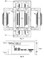
- Fig. 5 shows schematically the second embodiment of the integrated inductor
- Fig. 6 shows the example of its application in the resonant power supply circuit.
- the second embodiment is equivalent to the first one except for the fact that it contains two air gaps G1 located at the ends of the column 11, between the magnetic element of column 11 and the yoke 21, 22.
- the advantage of this solution over the configuration comprising a single gap G in the middle of the column 11 is that it allows to achieve the self-screening effect of magnetic field from air gaps (reduction in electromagnetic emission, minimization of losses associated with magnetic field near the air gap and minimization of couplings between magnetic elements through the external yoke) and allows to maintain a symmetry of magnetic fields distribution (equal number of volts-per-turn, independently on the position on the column).
- the second embodiment similarly as the first one, comprises air gaps G2 in the yoke connecting the column 11, around which the transformer windings are wound, with the columns 14 and 15 with the resonant inductor windings L2A, L2B, L3A, L3B.
- the direction of magnetic induction produced by the transformer winding L1 is shown with a dashed line and the direction of magnetic induction produced by he resonant inductor windings L2A, L2B is represented by a dashed-and-dotted line.
- the height of the column 11 is larger than the distance between the column 11 and columns 14, 15, and therefore the transformer winding L1 can be wound as a single-layer winding or, in the case of a larger length of the column 11, as a pitched winding.
- a single-layer wound transformer winding L1 allows to reduce windings losses (reduction of the proximity effect) and also to attain as large as possible relative length of the common magnetic path (losses reduction in magnetic material) and enables a flat, planar construction. Reduction in parasitic capacitances of the transformer windings enables to increase the operating frequency.
- Fig. 7 shows schematically the third embodiment of the integrated inductor
- Fig. 8 shows the example of its application in the resonant power supply circuit.
- the integrated inductor according to the third embodiment differs from the integrated inductor according to the second embodiment in that it has a four-element resonant inductor which, apart of windings L2A, L2B wound around columns 14, 15 parallel to the column 11, has also windings L2C, L2D wound around columns 16, 17 parallel to the yoke 12, 13. That allows to additionally increase the volume of the magnetic material in which the reduction of magnetic induction occurs and, consequently, reduction of losses in the magnetic core.
- the solution incorporates a quality-factor limiting circuit that consists of the control winding L3 connected with inductor L5 and a diode voltage limiter PD1.
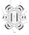
- Fig. 9 shows schematically the fourth embodiment of the integrated inductor's spatial structure wherein the six-part resonant inductor's windings L2A, L2B, L2C, L2D, L2E, L2F, L3A, L3B, L3C, L3D, L3E, L3F are wound around columns 31, 32, 33, 34, 35, 36, arranged circumferentially around the column11 carrying the transformer winding.
- the columns 31-36 can be curvilinear and in this embodiment they have the form of a half of a torus and thus facilitate the construction of a bobbin (also in the toroidal form) and winding of coils, and enable achieving significant reduction in core losses.
- the circumferential arrangement of columns 31-36 allows minimization of air gaps and thus effective reduction of magnetic flux leakage from the integrated magnetic element as well as compact, low profile construction and, consequently, substantial reduction of parasitic inter-turn capacitances.
Description
- The present invention relates to an integrated inductor for use in resonant energy-conversion systems ensuring minimization of losses in a ferromagnetic core and to a method for reduction of losses in an integrated inductor.
- Resonant energy-conversion systems, despite of their advantages, such as sinusoidal currents, soft switching capability, wide operating frequency range, etc., are relatively slowly superseding the classical solutions based on hard switching. The reason is that in a resonant circuit the peak current values are substantially exceeding the maximum load current. Therefore, the reactance elements, both the capacitors and inductors, shall be designed to store relatively large amounts of energy. This problem can be solved by increasing both the weight and dimensions of reactance elements. However, such approach is not economically viable, since it entails additional costs and, consequently, a higher price. A further unfavourable effect is the decrease in energy efficiency, because the increase in the inductive elements dimensions in resonant energy-conversion systems results in considerable losses in windings, particularly at frequencies above 100kHz. Also increasing the ferromagnetic core dimensions, while maintaining a constant rms value of the magnetic flux density is the reason that losses increase linearly with the core volume. Recently, due to rising electricity prices and legislative measures aimed at limitation of electric power consumption and its rational utilization, the energy efficiency becomes the crucial parameter influencing the potential success of the proposed solution.
- The
US Patent No. 5,886,516 presents an integrated multi-winding magnetic element intended for operation in a series resonant converter, in which on a single "UU" gapped magnetic core there are located two windings of an isolation transformer and two additional windings constituting two inductive elements of the resonant circuit. This assembly constitutes a resonant circuit consisting of three inductances, two capacitances and the isolation transformer. - An integrated-magnetic apparatus is known from the
US Patent No. 5,726,615 comprising three ferromagnetic pot cores, two of which have central core-columns carrying two flat windings placed around these columns. These two inductive elements constitute a transformer. The third ferromagnetic pot core has a shorter central core-column around which a flat winding is placed. The third core-piece located adjacent to a flat exterior surface of the transformer allows to form the third inductive element. The third inductive element is partially coupled magnetically through an air gap to the other windings and is phased to have the magnetic induction in the same direction as the magnetic induction in the ungapped magnetic circuit. - The
US Patent No. 7,525,406 presents a structure that contains a plurality of coupled and non-coupled inductive elements and at least one closed magnetic circuit comprised of mutually contiguous magnetic elements having groves for current conductors in the X-axis and a perpendicular Y-axis. The current conductors located along the same axis exhibit mutual inductance but none between mutually orthogonal axes. - The Polish patent application No.
393133 presents a method for increasing the power transferred by an integrated inductor characterized by positioning an integrated inductor's windings orthogonally with respect to each other and the choice of induction elements values so that magnetic flux of the auxiliary magnetic circuit is transferred through at least a portion of the main magnetic circuit transferring the main magnetic flux while both magnetic induction vectors are oriented orthogonally with respect to each other, in addition both variable in time magnetic induction vectors are shifted with respect to each other in the time domain. - The
US Patent No. 5,600,293 discloses an integrated inductor comprising a multi-winding inductor having a transformer winding and a resonant inductor, wherein sections, of the magnetic circuit of the transformer winding are incorporated into magnetic circuits of at least two parts of the resonant inductor so as to form common parts of magnetic circuit of the multi-winding inductor and at least two-part resonant inductor wherein the transformer winding of the multi-winding inductor is wound around a column, which has at least one air gap having a width. - In the article "1MHz-1kW LLC Resonant Converter with Integrated Magnetics", Zhang, Yanjun Xu, Dehong Mino, Kazuaki Sasagawa, Kiyoaki, Applied Power Electronics Conference, APEC 2007 - Twenty Second Annual IEEE, Feb. 25 2007-March 1 2007, pp. 955-961, there is described an integrated magnetic module in which the region of magnetic induction compensation is restricted to a small portion of the magnetic core volume. Moreover, in this element there occurs a problem of large resonant induction values with respect to the transformer induction value and also a relatively large effect of increasing the resistance of copper windings being in magnetic field from air gaps in magnetic circuits.
- The article "Planar Integrated Magnetics Design in Wide Input Range DC-DC Converter for Fuel Cell Application", Ziwei Ouyang, Zhe Zhang, Ole C. Thomsen, Michael A. E. Andersen, Ole Poulsen, Thomas Björklund, Energy Conversion Congress and Exposition (ECCE), 2010 IEEE: 12-16 Sept. 2010, pp. 4611-4618, also describes an integrated magnetic module in which the region of magnetic induction compensation is restricted to a small portion of the magnetic core volume. In this solution, a so-called hot spot occurs, where magnetic induction vectors produced by inductive elements of integrated magnetic circuits are summing up.
- The above examples illustrate integrated reactances intended for use in resonant DC/DC converters. Nevertheless, said integrated reactances do not fully utilize the multi-winding inductor as an output transformer in resonant energy-conversion systems, and therefore, a reduction of thermal losses in inductive elements of the resonant circuit.
- It would be, therefore, advisable to develop an integrated reactance element, characterized by reduced thermal losses in its resonant circuit inductive elements, and suitable for use in resonant DC/DC converters.
- The object of the invention is an integrated inductor according to
claim 1. - Preferably, the transformer winding of the multi-winding inductor is wound around the column in a single layer.
- Preferably, the transformer winding of the multi-winding inductor is a pitched winding wound around the column.
- The column, over which the transformer winding of the multi-winding inductor is wound, comprises two air gaps at its ends.
- Preferably, the integrated inductor it comprises magnetic core-pieces that constitute a magnetic circuit with parallel columns magnetically connected with the yoke whereas the transformer winding of the multi-winding inductor is wound on the column parallel to columns on which the windings, of the resonant inductor are wound.
- Preferably, the integrated inductor further comprises columns, parallel to the yoke, with further windings of the resonant inductor which are wound around said columns.
- Perferably, a resonant power supply comprises the integrated inductor according to the invention, wherein the multi-winding inductor is adapted to act as the output transformer and the inductive element is connected in series through the resonant inductor with with transistor switches.
- The invention is shown by means of exemplary embodiments on a drawing, in which:
-
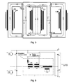
Fig. 1 shows a half-bridge structure of a multi-resonance power supply with a quality-factor limiter based on an integrated inductor ZER according to the first embodiment. -
Fig. 2 shows the first embodiment of the integrated inductor wherein variable magnetic inductions produced by the multi-winding inductor, which also functions as an output transformer, and by the resonant inductor, are oriented parallel with respect to each other in such a manner that the resultant time-variable vector of both magnetic inductions attains its minimum value. -
Fig. 3 shows exemplary simulation of magnetic induction distribution in the integrated inductor according to the first embodiment wherein the current flowing in the resonant inductor L2=L2A+L2B equals 0 arbitrary units, whereas the current flowing in the L1 coil equals 0.67 arbitrary units. The central column of the magnetic core incorporates an air gap. -
Fig. 4 shows exemplary simulation of magnetic induction distribution in the integrated inductor according to the first embodiment, wherein the current in the resonant inductor L2=L2A+L2B equals 1 arbitrary unit, whereas the current in the L1 coil equals 0.67 arbitrary units. The magnetic core central column incorporates an air gap and the directions of currents are chosen so that they are opposite in phase (a 180° phase shift). -
Fig. 5 shows schematically the second embodiment of the integrated inductor, andFig. 6 shows the example of its application in a resonant power supply circuit. -
Fig. 7 shows schematically the third embodiment of the integrated inductor, andFig. 8 shows the example of its application in a resonant power supply circuit. -
Fig. 9 shows schematically the fourth embodiment of the integrated inductor's spatial structure. -
Fig. 1 shows the first example of application of the integrated inductor according to the invention in a resonant-mode power supply circuit. The integrated inductor ZER1 comprises a resonant inductor L2 consisting of two inductive elements L2A and L2B connected in series and a multi-winding inductor, which also acts as the output transformer, composed of three inductive elements L1, L3, L4 having a common magnetic circuit. The inductive element L1 is connected in series through the inductor L2=L2A+L2B with transistor switches K1, K2; the output winding L4 and the quality-factor limiter winding L3 and the inductor L5 are connected to the diode voltage limiter PD1. The primary winding is also connected with the capacitive circuit C2=C2A+C2B. Due to a series connection of the capacitive circuit C2=C2A+C2B with the inductor L2=L2A+L2B, the resulting impedance of these elements is strongly dependent on frequency, which allows controlling the voltage provided to the secondary winding L4 of the multi-winding inductor. Because at resonance, the value of the voltage at the winding of the multi-winding inductor may achieve high values, a circuit for limiting good has been employed, which forms a control winding L3 connected with the inductor L5 and a diode viotabe limiter PD1. -
Fig. 2 shows the first embodiment of the integrated inductor according to the invention. The integrated inductor comprises two "E" shaped core-pieces assembled with their legs joined together and two "U" shaped core-pieces whose legs are joined to the corners of said two "E" shaped core-pieces. These core-pieces constitutecolumns column 11. Theintermediate columns outer columns yokes Fig. 3 and Fig. 4 the preferable directions of magnetic induction produced by the integrated inductor windings are depicted in the form of curves drawn in dashed lines with arrowheads indicating the direction, while inFig. 3 the current flows only through the element L1, whereas inFig. 4 through elements L1 and L2. An advantageous feature of the integrated inductor shown inFig. 2 is the ease of adjustment to different values of power transferred by means of typical magnetic elements of a suitable size. Due to parallel positioning of the multi-winding inductor winding L1 with respect to resonant inductors' windings L2A and L2B, the magnetic inductions produced by these windings are also parallel oriented. The winding L3, most often wound over the L1 winding, is not shown inFig. 2 to increase its clarity. Furthermore, depending on the phase shift between both magnetic induction vectors achieved by means of an appropriate choice of relative values of the reactance elements incorporated in the resonant-mode power supply or by choice of an appropriate topology, the amplitude of magnetic induction can be reduced within a certain range and, consequently, a reduction of losses in the magnetic core can be achieved. For this purpose, the phase shifts between the magnetic inductions superimposing in a selected portion of the magnetic circuit are chosen so as to achieve the smallest possible losses. Preferably, the phase shift between magnetic induction vectors produced by inductors L1 and L2 is basically 180°. - It is well known to describe the losses in a ferromagnetic core by the equation:

- The losses PV(B,f,T) in a ferromagnetic core depend primarily on the magnetic induction B, the magnetic field frequency f and the core temperature T, whereas:


- PV(T) attains its minimum near 90°C.
- In the resonant-mode power supply according to
Fig. 1 it is possible to achieve a constant phase shift of ca. +/-90° between the current in the inductor L2A and L2B and the current in the multi-winding inductor winding L1. Assuming equal amplitudes of the magnetic induction vectors, the resultant magnetic induction amplitude in the magnetic circuit portion where both magnetic fluxes are superimposing is:

- Assuming both induction vectors are on the same plane but opposite in phase (a 180° phase shift) and assuming for sinusoidal waveforms the same amplitude of the inductions associated with coils (L1) and (L2=L2A+L2B) BA1=BA2=BA, and if magnetic fields are shaped so that they cancel out, the resultant magnetic induction B12(t) in certain regions is BA12 :

- The integrated inductor according to the invention has a particularly desirable feature that two inductive elements L2A, L2B utilize
portions -
Fig. 3 and Fig. 4 show results of simulation of the magnetic induction vector distribution in the integrated inductor according to the invention.Fig. 3 illustrates the integrated inductor condition when the resonant inductor L2=L2A+L2B current equals 0 arbitrary units and the coil L1 current is 0.67 arbitrary units. The central column of the magnetic core incorporates an air gap. This is the initial condition, which is the basis for comparison because there are no compensating magnetic inductions from the resonant inductor. -
Fig. 4 shows simulation of the magnetic induction vector distribution in the integrated inductor in which the resonant inductor L2=L2A+L2B current equals 1 arbitrary unit and the current in coil L1 is 0.67 arbitrary units. The central column of the magnetic core incorporates an air gap and directions of currents in windings L1 and L2 are chosen so that they are phase-shifted by 180°. In the external branches of the ferromagnetic core, the magnetic induction current has been decreased from a value of 0.8 arbitrary units to the value of 0.45 arbitrary units. In such a situation, it is possible to assess a relative change of the power of losses, assuming that there is a square relationship between the value of power of losses in the core and the value of the magnetic induction:
- If, for example, the magnetic induction amplitude is reduced within 33% of the core volume and the magnetic induction amplitude decreases from 0.8 arbitrary units to 0.45 arbitrary units then, due to the reduction of magnetic induction within 33% of the core volume, thermal losses in chosen portions of the magnetic circuit decrease by 67% and by 20% in the whole core.
-
Fig. 5 shows schematically the second embodiment of the integrated inductor, andFig. 6 shows the example of its application in the resonant power supply circuit. The second embodiment is equivalent to the first one except for the fact that it contains two air gaps G1 located at the ends of thecolumn 11, between the magnetic element ofcolumn 11 and theyoke column 11 is that it allows to achieve the self-screening effect of magnetic field from air gaps (reduction in electromagnetic emission, minimization of losses associated with magnetic field near the air gap and minimization of couplings between magnetic elements through the external yoke) and allows to maintain a symmetry of magnetic fields distribution (equal number of volts-per-turn, independently on the position on the column). The second embodiment, similarly as the first one, comprises air gaps G2 in the yoke connecting thecolumn 11, around which the transformer windings are wound, with thecolumns - The direction of magnetic induction produced by the transformer winding L1 is shown with a dashed line and the direction of magnetic induction produced by he resonant inductor windings L2A, L2B is represented by a dashed-and-dotted line. In the second embodiment the height of the
column 11 is larger than the distance between thecolumn 11 andcolumns column 11, as a pitched winding. A single-layer wound transformer winding L1 allows to reduce windings losses (reduction of the proximity effect) and also to attain as large as possible relative length of the common magnetic path (losses reduction in magnetic material) and enables a flat, planar construction. Reduction in parasitic capacitances of the transformer windings enables to increase the operating frequency. -
Fig. 7 shows schematically the third embodiment of the integrated inductor, andFig. 8 shows the example of its application in the resonant power supply circuit. The integrated inductor according to the third embodiment differs from the integrated inductor according to the second embodiment in that it has a four-element resonant inductor which, apart of windings L2A, L2B wound aroundcolumns column 11, has also windings L2C, L2D wound aroundcolumns yoke - Since under resonance conditions the voltage across the multi-winding inductor may attain large values, the solution incorporates a quality-factor limiting circuit that consists of the control winding L3 connected with inductor L5 and a diode voltage limiter PD1.
-
Fig. 9 shows schematically the fourth embodiment of the integrated inductor's spatial structure wherein the six-part resonant inductor's windings L2A, L2B, L2C, L2D, L2E, L2F, L3A, L3B, L3C, L3D, L3E, L3F are wound aroundcolumns
Claims (9)
- An integrated inductor comprising a multi-winding inductor having a transformer winding (L1) and a resonant inductor winding (L2), both windings (L1, L2) wound around a magnetic core comprising core pieces that form a central column (11) which is surrounded by a closed magnetic circuit of connected magnetic elements of columns (12, 13) and yokes (21, 22) to which C-shaped (14, 15) and/ or E-shaped (16, 17) magnetic elements are connected, wherein the core pieces form a closed magnetic circuit, and wherein:- the resonant inductor winding (L2) comprises at least two resonant inductor winding parts (L2A, L2B),- wherein the multi-winding inductor is configured such that, when in use, currents flow simultaneously through the transformer winding (L1) and the resonant inductor winding (L2), the magnetic induction in the magnetic circuit of the transformer winding (L1) overlaps with the magnetic induction in the magnetic circuit of the resonant inductor winding parts (L2A, L2B) in an area of common parts (1), (2) of the magnetic core,- wherein the transformer winding (L1) of the multi-winding inductor is wound around the central column (11) of the magnetic core,- wherein a first air gap (G) is formed in the central column (11) or a pair of first air gaps (G1) is formed at the ends of the central column (11);- and wherein the resonant inductor winding parts (L2A, L2B; L2C, L2D) are would around the C-shaped (14, 15) and/or E-shaped (16, 17) magnetic elements of the magnetic core,- wherein second air gaps (G2) are formed between the closed magnetic circuit of magnetic elements (12, 13, 21, 22) and the C-shaped (14, 15) and/or E-shaped (16, 17) magnetic elements;- and wherein the first air gap (G) or the pair of the first air gaps (G1) have a width adapted so that the magnetic induction produced by the resonant inductor winding (L2) does not exceed 25% of the magnetic induction produced by the transformer winding (L1) in the central column (11) while currents flow simultaneously through both the transformer winding (L1) and the resonant inductor winding (L2).
- The integrated inductor according to claim 1, characterized in that the transformer winding (L1) of the multi-winding inductor is wound around the central column (11) in a single layer.
- The integrated inductor according to claim 2, characterized in that the transformer winding (L1) of the multi-winding inductor is a pitched winding wound around the central column (11).
- The integrated inductor according to any preceding claim characterized in that the central column (11) and the closed magnetic circuit of magnetic elements (12, 13, 21, 22) are formed by two E-shaped magnetic elements connected by the ends of the top and bottom legs of the E shape.
- The integrated inductor according to any preceding claim characterized in that the central column (11) is formed by an I-shaped magnetic element and the closed magnetic circuit of magnetic elements (12, 13, 21, 22) is formed by two C-shaped magnetic elements connected by the ends of the legs of the C shape.
- The integrated inductor according to claim 4 or 5, characterized in that it comprises a pair of further C-shaped magnetic elements (14, 15) arranged oppositely to each other.
- The integrated inductor according to claim 4 or 5, characterized in that it comprises a pair of further C-shaped magnetic elements (14, 15; 16, 17) arranged oppositely to each other around the closed magnetic circuit of magnetic elements (12, 13, 21, 22), and a pair of further E-shaped magnetic elements (14, 15; 16, 17) arranged oppositely to each other around the closed magnetic circuit of magnetic elements (12, 13, 21, 22).
- The integrated inductor according to claim 4 or 5, characterized in that it comprises a plurality of C-shaped magnetic elements (31-36) circumferentially arranged around the closed loop of magnetic elements, wherein the resonant inductor windings (L2A, L2B, L2C, L2D, L2E, L2F) are wound on the C-shaped magnetic elements (31-36).
- A resonant power supply comprising the integrated inductor according to any of preceding claims, wherein the multi-winding inductor acts as the output transformer and the transformer winding (L1) is connected in series through the resonant inductor winding (L2) with transistor switches (K1, K2).
Applications Claiming Priority (2)
| Application Number | Priority Date | Filing Date | Title |
|---|---|---|---|
| PL394316A PL221896B1 (en) | 2011-03-23 | 2011-03-23 | Method for reducing losses in an integrated inductive element and the integrated inductive element |
| PCT/EP2012/055099 WO2012126993A2 (en) | 2011-03-23 | 2012-03-22 | An integrated inductor and a method for reduction of losses in an integrated inductor |
Publications (2)
| Publication Number | Publication Date |
|---|---|
| EP2689433A2 EP2689433A2 (en) | 2014-01-29 |
| EP2689433B1 true EP2689433B1 (en) | 2015-07-01 |
Family
ID=45953100
Family Applications (1)
| Application Number | Title | Priority Date | Filing Date |
|---|---|---|---|
| EP12713924.4A Not-in-force EP2689433B1 (en) | 2011-03-23 | 2012-03-22 | An integrated inductor and a method for reduction of losses in an integrated inductor |
Country Status (6)
| Country | Link |
|---|---|
| US (1) | US9514875B2 (en) |
| EP (1) | EP2689433B1 (en) |
| CN (1) | CN103635979A (en) |
| CA (1) | CA2829807A1 (en) |
| PL (1) | PL221896B1 (en) |
| WO (1) | WO2012126993A2 (en) |
Cited By (2)
| Publication number | Priority date | Publication date | Assignee | Title |
|---|---|---|---|---|
| CN107393705A (en) * | 2016-03-11 | 2017-11-24 | 马克西姆综合产品公司 | Integrated transformer and coupling inductor and associated switch power converter and method |
| EP3496115A1 (en) | 2017-12-08 | 2019-06-12 | Fideltronik Poland sp. z o.o. | An integrated transformer-inductor assembly |
Families Citing this family (30)
| Publication number | Priority date | Publication date | Assignee | Title |
|---|---|---|---|---|
| CN103078472B (en) * | 2012-10-25 | 2015-01-07 | 中国船舶重工集团公司第七二三研究所 | Integrated integration method for magnetic assembly of high-voltage power supply of microwave power module |
| CN103595367B (en) * | 2013-11-07 | 2017-03-08 | 华为技术有限公司 | A kind of magnetic integrated device and a kind of circuit for power conversion |
| CN103903840B (en) * | 2014-04-16 | 2017-05-10 | 沈阳工业大学 | Power transformer with magnetic bias compensating function |
| US9814108B2 (en) | 2014-04-25 | 2017-11-07 | Philips Lighting Holding B.V. | Switched mode power supply driver integrated with a power transmission antenna |
| WO2015192133A2 (en) | 2014-06-13 | 2015-12-17 | University Of Maryland | An integrated dual-output grid-to-vehicle (g2v) and vehicle-to-grid (v2g) onboard charger for plug-in electric vehicles |
| CN104022698A (en) * | 2014-06-20 | 2014-09-03 | 沈阳工业大学 | Novel power transformer control system with both direct-current magnetic bias function and reactive compensation function |
| EP2978119A1 (en) * | 2014-07-23 | 2016-01-27 | Transon Power Units BV | Transformer based switched power converter with switched capacitor auxiliary dc/dc converter |
| CN105719784B (en) * | 2014-07-23 | 2019-01-15 | 杨玉岗 | A kind of integrated coupling inductor of mu character shape magnetic |
| CN105336484B (en) | 2014-08-06 | 2018-05-01 | 上海电科电器科技有限公司 | Current transformer |
| US10763028B2 (en) * | 2015-04-10 | 2020-09-01 | Delta Electronics, Inc. | Magnetic component and magnetic core of the same |
| TWI557759B (en) * | 2015-04-10 | 2016-11-11 | 台達電子工業股份有限公司 | Integrated inductor and integrated inductor magnetic core of the same |
| CN106469602A (en) * | 2015-08-20 | 2017-03-01 | 艾默生网络能源有限公司 | A kind of magneticss, switching device and electrical equipment |
| US10910150B2 (en) * | 2015-11-30 | 2021-02-02 | Intel Corporation | Reconfigurable coupled inductor |
| CN106998142B (en) * | 2016-01-25 | 2019-08-30 | 台达电子企业管理(上海)有限公司 | Controlled resonant converter, the inductance of multi-channel parallel integrate magnetic element and transformer integrates magnetic element |
| CN107134358A (en) * | 2016-02-26 | 2017-09-05 | 艾默生网络能源有限公司 | A kind of inductance winding method and device |
| CN105761880B (en) * | 2016-04-20 | 2017-12-29 | 华为技术有限公司 | A kind of thin film inductor and power-switching circuit |
| US9959972B2 (en) | 2016-08-08 | 2018-05-01 | Witricity Corporation | Inductor system having shared material for flux cancellation |
| CN107919216B (en) * | 2017-11-01 | 2019-07-23 | 西安交通大学 | A kind of magnetic integrates hybrid distribution transformer |
| US10186949B1 (en) * | 2017-11-09 | 2019-01-22 | International Business Machines Corporation | Coupled-inductor DC-DC power converter |
| DE102018203263A1 (en) * | 2018-03-06 | 2019-09-12 | Audi Ag | Charging device for a motor vehicle |
| DE102018112100A1 (en) * | 2018-05-18 | 2019-12-05 | Tdk Electronics Ag | Choke with high common mode inductance |
| US11750087B2 (en) * | 2018-05-24 | 2023-09-05 | Astec International Limited | Totem pole bridgeless PFC power converters |
| CN108777220B (en) * | 2018-05-28 | 2022-01-21 | 台达电子工业股份有限公司 | Magnetic element and switching power supply device |
| CN111740631B (en) * | 2019-03-19 | 2021-11-02 | 台达电子工业股份有限公司 | Resonant converter and method for manufacturing transformer thereof |
| US20210012944A1 (en) * | 2019-07-08 | 2021-01-14 | North Carolina State University | Transformer designs for very high isolation with high coupling |
| CN110310818A (en) * | 2019-07-23 | 2019-10-08 | 浙江万安亿创电子科技有限公司 | A kind of resonant inductance |
| US11521792B2 (en) * | 2019-09-16 | 2022-12-06 | Utah State University | Wireless power transfer with active field cancellation using multiple magnetic flux sinks |
| CN111010045B (en) * | 2019-12-29 | 2022-10-25 | 国网河北省电力有限公司雄安新区供电公司 | Double-active-bridge converter for direct-current power distribution network |
| US11881340B2 (en) * | 2020-01-22 | 2024-01-23 | Murata Manufacturing Co., Ltd. | Inductor structure |
| US11616397B2 (en) * | 2020-08-12 | 2023-03-28 | Medtronic, Inc. | Magnetic alignment of transcutaneous energy transfer coils |
Family Cites Families (27)
| Publication number | Priority date | Publication date | Assignee | Title |
|---|---|---|---|---|
| US1606777A (en) * | 1923-05-08 | 1926-11-16 | Western Electric Co | Inductance device |
| US3876938A (en) * | 1972-06-19 | 1975-04-08 | Kabushikikaisha Tokyo Keiki To | Magnetic switch for a pulse generator, receiver, and transducer |
| DE3305708A1 (en) * | 1983-02-18 | 1984-08-23 | Transformatoren Union Ag, 7000 Stuttgart | THREE-PHASE THROTTLE COIL WITH FIFTH LEG CORE |
| CA1258881A (en) * | 1987-04-15 | 1989-08-29 | Leonard Bolduc | Self-regulated transformer with gaps |
| US4975649A (en) * | 1989-12-18 | 1990-12-04 | Albar, Inc. | Method and apparatus for sensing loss of regulation in a ferroresonant transformer |
| US5225784A (en) * | 1991-02-25 | 1993-07-06 | National Research Council Of Canada | DC Current comparator circuit for generating an adjustable output proportional to an input signal |
| US5416458A (en) * | 1991-04-25 | 1995-05-16 | General Signal Corporation | Power distribution transformer for non-linear loads |
| US5194817A (en) * | 1991-07-18 | 1993-03-16 | James G. Biddle Co. | Apparatus and method for testing insulation using a pulsed resonant power supply |
| US5726615A (en) | 1994-03-24 | 1998-03-10 | Bloom; Gordon E. | Integrated-magnetic apparatus |
| CN2202369Y (en) * | 1994-05-03 | 1995-06-28 | 中国矿业大学 | Automatic following and compensating petersen coil |
| US5600293A (en) * | 1994-06-14 | 1997-02-04 | The United States Of America As Represented By The Secretary Of The Army | Integrated magnetic exploding foil initiator fire set |
| US5684678A (en) * | 1995-12-08 | 1997-11-04 | Delco Electronics Corp. | Resonant converter with controlled inductor |
| US5768112A (en) | 1997-05-30 | 1998-06-16 | Delco Electronics Corp. | Sub-resonant series resonant converter having improved form factor and reduced EMI |
| US6606260B2 (en) * | 2001-10-29 | 2003-08-12 | The Chamberlain Group, Inc. | Switch mode power supply for a telephone entry system or the like |
| US6975098B2 (en) * | 2002-01-31 | 2005-12-13 | Vlt, Inc. | Factorized power architecture with point of load sine amplitude converters |
| AU2003260419A1 (en) * | 2002-10-30 | 2004-05-25 | Pyongyang Technical Trading Centre | Transformer |
| SE525698C2 (en) * | 2003-06-27 | 2005-04-05 | Forskarpatent I Syd Ab | Transformer with protection against direct current magnetization caused by zero sequence current |
| US7136293B2 (en) * | 2004-06-24 | 2006-11-14 | Petkov Roumen D | Full wave series resonant type DC to DC power converter with integrated magnetics |
| CN2796210Y (en) * | 2005-05-11 | 2006-07-12 | 中国矿业大学 | Zero frequency short circuit high resistance earthed transformer type arc extinguishing coil |
| KR100547289B1 (en) * | 2005-05-18 | 2006-01-26 | 주식회사 피에스텍 | Synchronous rectifier type series resonant converter for operating in intermittence mode |
| TWI326917B (en) * | 2007-02-01 | 2010-07-01 | Ind Tech Res Inst | Phase-change memory |
| KR101004823B1 (en) * | 2007-12-27 | 2010-12-28 | 삼성전기주식회사 | Transformer improved leakage inductance |
| US7525406B1 (en) | 2008-01-17 | 2009-04-28 | Well-Mag Electronic Ltd. | Multiple coupling and non-coupling inductor |
| KR100975926B1 (en) * | 2008-08-08 | 2010-08-13 | 삼성전기주식회사 | Transformer having resonance inductance |
| EP2299456B1 (en) * | 2009-09-17 | 2016-08-24 | DET International Holding Limited | Integrated magnetic component |
| US8120457B2 (en) * | 2010-04-09 | 2012-02-21 | Delta Electronics, Inc. | Current-controlled variable inductor |
| PL219054B1 (en) | 2010-12-03 | 2015-03-31 | Akademia Górniczo Hutnicza Im Stanisława Staszica W Krakowie | Method for increasing the electric power transmitted by the integrated inductive element and integrated inductive element |
-
2011
- 2011-03-23 PL PL394316A patent/PL221896B1/en unknown
-
2012
- 2012-03-22 CN CN201280014354.0A patent/CN103635979A/en active Pending
- 2012-03-22 US US14/005,268 patent/US9514875B2/en active Active
- 2012-03-22 WO PCT/EP2012/055099 patent/WO2012126993A2/en active Application Filing
- 2012-03-22 CA CA2829807A patent/CA2829807A1/en not_active Abandoned
- 2012-03-22 EP EP12713924.4A patent/EP2689433B1/en not_active Not-in-force
Cited By (2)
| Publication number | Priority date | Publication date | Assignee | Title |
|---|---|---|---|---|
| CN107393705A (en) * | 2016-03-11 | 2017-11-24 | 马克西姆综合产品公司 | Integrated transformer and coupling inductor and associated switch power converter and method |
| EP3496115A1 (en) | 2017-12-08 | 2019-06-12 | Fideltronik Poland sp. z o.o. | An integrated transformer-inductor assembly |
Also Published As
| Publication number | Publication date |
|---|---|
| PL394316A1 (en) | 2012-09-24 |
| CN103635979A (en) | 2014-03-12 |
| US20140043127A1 (en) | 2014-02-13 |
| CA2829807A1 (en) | 2012-09-27 |
| EP2689433A2 (en) | 2014-01-29 |
| WO2012126993A2 (en) | 2012-09-27 |
| US9514875B2 (en) | 2016-12-06 |
| WO2012126993A3 (en) | 2012-11-15 |
| PL221896B1 (en) | 2016-06-30 |
Similar Documents
| Publication | Publication Date | Title |
|---|---|---|
| EP2689433B1 (en) | An integrated inductor and a method for reduction of losses in an integrated inductor | |
| US10211745B2 (en) | Resonant LLC converter with a multi-leg transformer with gapped center leg | |
| EP3136404B1 (en) | Coupling inductor | |
| EP2624260B1 (en) | Forward converter with magnetic component | |
| US20170054378A1 (en) | Integrated magnetic component | |
| TWI497908B (en) | Method of improving performance of wave filter and power conversion device using same | |
| US20050002206A1 (en) | Method and apparatus for substantially reducing electrical displacement current flow between input and output circuits coupled to input and output windings of an energy transfer element | |
| US11398344B2 (en) | Transformer | |
| US7138787B2 (en) | DC/DC converter | |
| US8379415B2 (en) | Systems and methods for reducing EMI in switch mode converter systems | |
| US20150228397A1 (en) | Coiled power device comprising a winding of a first coiling and a winding of a second coiling which cover the same portion of a magnetic core member | |
| JP6533342B2 (en) | Composite smoothing inductor and smoothing circuit | |
| US20140286054A1 (en) | Inductive component and use | |
| US20180241300A1 (en) | Variable inductor apparatuses systems and methods | |
| JP2016213383A (en) | Magnetic component and power supply circuit using the same | |
| JP6278153B1 (en) | Transformer | |
| US10985574B2 (en) | Resonant power transfer | |
| EP2647117B1 (en) | Resonant power supply with an integrated inductor | |
| US20170040097A1 (en) | Switching converter circuit with an integrated transformer | |
| Rehlaender et al. | An integrated transformer for LLC resonant converter applications of low output voltages and high currents | |
| Khalid et al. | Design And Analysis Of A New Inductive Coil With Improved Characteristics Than Conventional Magnetic Couplers | |
| CN219626421U (en) | Current control type magnetic valve type flexible inductor, transformer and LLC resonant converter | |
| Poongothai et al. | Analysis of High Frequency, High Ratio Transformer configurations for DC-DC Converter Applications | |
| Valtchev et al. | Contactless energy transmission with optimal efficiency | |
| CN116936219A (en) | Current control type magnetic valve type flexible inductor, transformer and LLC resonant converter |
Legal Events
| Date | Code | Title | Description |
|---|---|---|---|
| PUAI | Public reference made under article 153(3) epc to a published international application that has entered the european phase |
Free format text: ORIGINAL CODE: 0009012 |
|
| 17P | Request for examination filed |
Effective date: 20130918 |
|
| AK | Designated contracting states |
Kind code of ref document: A2 Designated state(s): AL AT BE BG CH CY CZ DE DK EE ES FI FR GB GR HR HU IE IS IT LI LT LU LV MC MK MT NL NO PL PT RO RS SE SI SK SM TR |
|
| DAX | Request for extension of the european patent (deleted) | ||
| RIC1 | Information provided on ipc code assigned before grant |
Ipc: H02M 3/28 20060101ALI20141128BHEP Ipc: H01F 27/28 20060101ALI20141128BHEP Ipc: H02M 1/00 20070101ALI20141128BHEP Ipc: H01F 27/38 20060101AFI20141128BHEP |
|
| GRAP | Despatch of communication of intention to grant a patent |
Free format text: ORIGINAL CODE: EPIDOSNIGR1 |
|
| GRAS | Grant fee paid |
Free format text: ORIGINAL CODE: EPIDOSNIGR3 |
|
| GRAA | (expected) grant |
Free format text: ORIGINAL CODE: 0009210 |
|
| INTG | Intention to grant announced |
Effective date: 20150508 |
|
| AK | Designated contracting states |
Kind code of ref document: B1 Designated state(s): AL AT BE BG CH CY CZ DE DK EE ES FI FR GB GR HR HU IE IS IT LI LT LU LV MC MK MT NL NO PL PT RO RS SE SI SK SM TR |
|
| REG | Reference to a national code |
Ref country code: GB Ref legal event code: FG4D |
|
| REG | Reference to a national code |
Ref country code: AT Ref legal event code: REF Ref document number: 734390 Country of ref document: AT Kind code of ref document: T Effective date: 20150715 Ref country code: CH Ref legal event code: EP Ref country code: NL Ref legal event code: T3 |
|
| REG | Reference to a national code |
Ref country code: SE Ref legal event code: TRGR |
|
| REG | Reference to a national code |
Ref country code: IE Ref legal event code: FG4D |
|
| REG | Reference to a national code |
Ref country code: DE Ref legal event code: R096 Ref document number: 602012008387 Country of ref document: DE |
|
| REG | Reference to a national code |
Ref country code: NO Ref legal event code: T2 Effective date: 20150701 |
|
| REG | Reference to a national code |
Ref country code: AT Ref legal event code: MK05 Ref document number: 734390 Country of ref document: AT Kind code of ref document: T Effective date: 20150701 |
|
| REG | Reference to a national code |
Ref country code: LT Ref legal event code: MG4D |
|
| PG25 | Lapsed in a contracting state [announced via postgrant information from national office to epo] |
Ref country code: LV Free format text: LAPSE BECAUSE OF FAILURE TO SUBMIT A TRANSLATION OF THE DESCRIPTION OR TO PAY THE FEE WITHIN THE PRESCRIBED TIME-LIMIT Effective date: 20150701 Ref country code: FI Free format text: LAPSE BECAUSE OF FAILURE TO SUBMIT A TRANSLATION OF THE DESCRIPTION OR TO PAY THE FEE WITHIN THE PRESCRIBED TIME-LIMIT Effective date: 20150701 Ref country code: LT Free format text: LAPSE BECAUSE OF FAILURE TO SUBMIT A TRANSLATION OF THE DESCRIPTION OR TO PAY THE FEE WITHIN THE PRESCRIBED TIME-LIMIT Effective date: 20150701 Ref country code: GR Free format text: LAPSE BECAUSE OF FAILURE TO SUBMIT A TRANSLATION OF THE DESCRIPTION OR TO PAY THE FEE WITHIN THE PRESCRIBED TIME-LIMIT Effective date: 20151002 |
|
| PG25 | Lapsed in a contracting state [announced via postgrant information from national office to epo] |
Ref country code: AT Free format text: LAPSE BECAUSE OF FAILURE TO SUBMIT A TRANSLATION OF THE DESCRIPTION OR TO PAY THE FEE WITHIN THE PRESCRIBED TIME-LIMIT Effective date: 20150701 Ref country code: IS Free format text: LAPSE BECAUSE OF FAILURE TO SUBMIT A TRANSLATION OF THE DESCRIPTION OR TO PAY THE FEE WITHIN THE PRESCRIBED TIME-LIMIT Effective date: 20151101 Ref country code: PL Free format text: LAPSE BECAUSE OF FAILURE TO SUBMIT A TRANSLATION OF THE DESCRIPTION OR TO PAY THE FEE WITHIN THE PRESCRIBED TIME-LIMIT Effective date: 20150701 Ref country code: RS Free format text: LAPSE BECAUSE OF FAILURE TO SUBMIT A TRANSLATION OF THE DESCRIPTION OR TO PAY THE FEE WITHIN THE PRESCRIBED TIME-LIMIT Effective date: 20150701 Ref country code: PT Free format text: LAPSE BECAUSE OF FAILURE TO SUBMIT A TRANSLATION OF THE DESCRIPTION OR TO PAY THE FEE WITHIN THE PRESCRIBED TIME-LIMIT Effective date: 20151102 Ref country code: HR Free format text: LAPSE BECAUSE OF FAILURE TO SUBMIT A TRANSLATION OF THE DESCRIPTION OR TO PAY THE FEE WITHIN THE PRESCRIBED TIME-LIMIT Effective date: 20150701 Ref country code: ES Free format text: LAPSE BECAUSE OF FAILURE TO SUBMIT A TRANSLATION OF THE DESCRIPTION OR TO PAY THE FEE WITHIN THE PRESCRIBED TIME-LIMIT Effective date: 20150701 |
|
| REG | Reference to a national code |
Ref country code: FR Ref legal event code: PLFP Year of fee payment: 5 |
|
| REG | Reference to a national code |
Ref country code: DE Ref legal event code: R097 Ref document number: 602012008387 Country of ref document: DE |
|
| PG25 | Lapsed in a contracting state [announced via postgrant information from national office to epo] |
Ref country code: CZ Free format text: LAPSE BECAUSE OF FAILURE TO SUBMIT A TRANSLATION OF THE DESCRIPTION OR TO PAY THE FEE WITHIN THE PRESCRIBED TIME-LIMIT Effective date: 20150701 Ref country code: DK Free format text: LAPSE BECAUSE OF FAILURE TO SUBMIT A TRANSLATION OF THE DESCRIPTION OR TO PAY THE FEE WITHIN THE PRESCRIBED TIME-LIMIT Effective date: 20150701 Ref country code: SK Free format text: LAPSE BECAUSE OF FAILURE TO SUBMIT A TRANSLATION OF THE DESCRIPTION OR TO PAY THE FEE WITHIN THE PRESCRIBED TIME-LIMIT Effective date: 20150701 Ref country code: EE Free format text: LAPSE BECAUSE OF FAILURE TO SUBMIT A TRANSLATION OF THE DESCRIPTION OR TO PAY THE FEE WITHIN THE PRESCRIBED TIME-LIMIT Effective date: 20150701 |
|
| PLBE | No opposition filed within time limit |
Free format text: ORIGINAL CODE: 0009261 |
|
| STAA | Information on the status of an ep patent application or granted ep patent |
Free format text: STATUS: NO OPPOSITION FILED WITHIN TIME LIMIT |
|
| PG25 | Lapsed in a contracting state [announced via postgrant information from national office to epo] |
Ref country code: RO Free format text: LAPSE BECAUSE OF FAILURE TO SUBMIT A TRANSLATION OF THE DESCRIPTION OR TO PAY THE FEE WITHIN THE PRESCRIBED TIME-LIMIT Effective date: 20150701 |
|
| 26N | No opposition filed |
Effective date: 20160404 |
|
| PG25 | Lapsed in a contracting state [announced via postgrant information from national office to epo] |
Ref country code: SI Free format text: LAPSE BECAUSE OF FAILURE TO SUBMIT A TRANSLATION OF THE DESCRIPTION OR TO PAY THE FEE WITHIN THE PRESCRIBED TIME-LIMIT Effective date: 20150701 Ref country code: BE Free format text: LAPSE BECAUSE OF NON-PAYMENT OF DUE FEES Effective date: 20160331 |
|
| PG25 | Lapsed in a contracting state [announced via postgrant information from national office to epo] |
Ref country code: MC Free format text: LAPSE BECAUSE OF FAILURE TO SUBMIT A TRANSLATION OF THE DESCRIPTION OR TO PAY THE FEE WITHIN THE PRESCRIBED TIME-LIMIT Effective date: 20150701 Ref country code: LU Free format text: LAPSE BECAUSE OF FAILURE TO SUBMIT A TRANSLATION OF THE DESCRIPTION OR TO PAY THE FEE WITHIN THE PRESCRIBED TIME-LIMIT Effective date: 20160322 |
|
| REG | Reference to a national code |
Ref country code: IE Ref legal event code: MM4A |
|
| PG25 | Lapsed in a contracting state [announced via postgrant information from national office to epo] |
Ref country code: BE Free format text: LAPSE BECAUSE OF FAILURE TO SUBMIT A TRANSLATION OF THE DESCRIPTION OR TO PAY THE FEE WITHIN THE PRESCRIBED TIME-LIMIT Effective date: 20150701 |
|
| PG25 | Lapsed in a contracting state [announced via postgrant information from national office to epo] |
Ref country code: IE Free format text: LAPSE BECAUSE OF NON-PAYMENT OF DUE FEES Effective date: 20160322 |
|
| REG | Reference to a national code |
Ref country code: FR Ref legal event code: PLFP Year of fee payment: 6 |
|
| PG25 | Lapsed in a contracting state [announced via postgrant information from national office to epo] |
Ref country code: MT Free format text: LAPSE BECAUSE OF FAILURE TO SUBMIT A TRANSLATION OF THE DESCRIPTION OR TO PAY THE FEE WITHIN THE PRESCRIBED TIME-LIMIT Effective date: 20150701 |
|
| REG | Reference to a national code |
Ref country code: FR Ref legal event code: PLFP Year of fee payment: 7 |
|
| PG25 | Lapsed in a contracting state [announced via postgrant information from national office to epo] |
Ref country code: SM Free format text: LAPSE BECAUSE OF FAILURE TO SUBMIT A TRANSLATION OF THE DESCRIPTION OR TO PAY THE FEE WITHIN THE PRESCRIBED TIME-LIMIT Effective date: 20150701 Ref country code: CY Free format text: LAPSE BECAUSE OF FAILURE TO SUBMIT A TRANSLATION OF THE DESCRIPTION OR TO PAY THE FEE WITHIN THE PRESCRIBED TIME-LIMIT Effective date: 20150701 Ref country code: HU Free format text: LAPSE BECAUSE OF FAILURE TO SUBMIT A TRANSLATION OF THE DESCRIPTION OR TO PAY THE FEE WITHIN THE PRESCRIBED TIME-LIMIT; INVALID AB INITIO Effective date: 20120322 |
|
| PG25 | Lapsed in a contracting state [announced via postgrant information from national office to epo] |
Ref country code: TR Free format text: LAPSE BECAUSE OF FAILURE TO SUBMIT A TRANSLATION OF THE DESCRIPTION OR TO PAY THE FEE WITHIN THE PRESCRIBED TIME-LIMIT Effective date: 20150701 Ref country code: MK Free format text: LAPSE BECAUSE OF FAILURE TO SUBMIT A TRANSLATION OF THE DESCRIPTION OR TO PAY THE FEE WITHIN THE PRESCRIBED TIME-LIMIT Effective date: 20150701 Ref country code: MT Free format text: LAPSE BECAUSE OF FAILURE TO SUBMIT A TRANSLATION OF THE DESCRIPTION OR TO PAY THE FEE WITHIN THE PRESCRIBED TIME-LIMIT Effective date: 20160331 |
|
| PG25 | Lapsed in a contracting state [announced via postgrant information from national office to epo] |
Ref country code: BG Free format text: LAPSE BECAUSE OF FAILURE TO SUBMIT A TRANSLATION OF THE DESCRIPTION OR TO PAY THE FEE WITHIN THE PRESCRIBED TIME-LIMIT Effective date: 20150701 |
|
| PG25 | Lapsed in a contracting state [announced via postgrant information from national office to epo] |
Ref country code: AL Free format text: LAPSE BECAUSE OF FAILURE TO SUBMIT A TRANSLATION OF THE DESCRIPTION OR TO PAY THE FEE WITHIN THE PRESCRIBED TIME-LIMIT Effective date: 20150701 |
|
| PGFP | Annual fee paid to national office [announced via postgrant information from national office to epo] |
Ref country code: IT Payment date: 20200323 Year of fee payment: 9 Ref country code: SE Payment date: 20200327 Year of fee payment: 9 Ref country code: GB Payment date: 20200327 Year of fee payment: 9 Ref country code: NL Payment date: 20200326 Year of fee payment: 9 Ref country code: NO Payment date: 20200327 Year of fee payment: 9 Ref country code: DE Payment date: 20200327 Year of fee payment: 9 |
|
| PGFP | Annual fee paid to national office [announced via postgrant information from national office to epo] |
Ref country code: FR Payment date: 20200325 Year of fee payment: 9 |
|
| PGFP | Annual fee paid to national office [announced via postgrant information from national office to epo] |
Ref country code: CH Payment date: 20200401 Year of fee payment: 9 |
|
| REG | Reference to a national code |
Ref country code: DE Ref legal event code: R119 Ref document number: 602012008387 Country of ref document: DE |
|
| REG | Reference to a national code |
Ref country code: NO Ref legal event code: MMEP |
|
| REG | Reference to a national code |
Ref country code: CH Ref legal event code: PL |
|
| REG | Reference to a national code |
Ref country code: NL Ref legal event code: MM Effective date: 20210401 |
|
| GBPC | Gb: european patent ceased through non-payment of renewal fee |
Effective date: 20210322 |
|
| PG25 | Lapsed in a contracting state [announced via postgrant information from national office to epo] |
Ref country code: NL Free format text: LAPSE BECAUSE OF NON-PAYMENT OF DUE FEES Effective date: 20210401 Ref country code: NO Free format text: LAPSE BECAUSE OF NON-PAYMENT OF DUE FEES Effective date: 20210331 Ref country code: LI Free format text: LAPSE BECAUSE OF NON-PAYMENT OF DUE FEES Effective date: 20210331 Ref country code: CH Free format text: LAPSE BECAUSE OF NON-PAYMENT OF DUE FEES Effective date: 20210331 Ref country code: GB Free format text: LAPSE BECAUSE OF NON-PAYMENT OF DUE FEES Effective date: 20210322 Ref country code: FR Free format text: LAPSE BECAUSE OF NON-PAYMENT OF DUE FEES Effective date: 20210331 Ref country code: SE Free format text: LAPSE BECAUSE OF NON-PAYMENT OF DUE FEES Effective date: 20210323 Ref country code: DE Free format text: LAPSE BECAUSE OF NON-PAYMENT OF DUE FEES Effective date: 20211001 |
|
| PG25 | Lapsed in a contracting state [announced via postgrant information from national office to epo] |
Ref country code: IT Free format text: LAPSE BECAUSE OF NON-PAYMENT OF DUE FEES Effective date: 20210322 |