EP2689152B1 - Link member for motion-enabled movie theatre chair - Google Patents
Link member for motion-enabled movie theatre chair Download PDFInfo
- Publication number
- EP2689152B1 EP2689152B1 EP12761436.0A EP12761436A EP2689152B1 EP 2689152 B1 EP2689152 B1 EP 2689152B1 EP 12761436 A EP12761436 A EP 12761436A EP 2689152 B1 EP2689152 B1 EP 2689152B1
- Authority
- EP
- European Patent Office
- Prior art keywords
- link member
- slider
- housing
- freedom
- axis
- Prior art date
- Legal status (The legal status is an assumption and is not a legal conclusion. Google has not performed a legal analysis and makes no representation as to the accuracy of the status listed.)
- Active
Links
Images




Classifications
-
- A—HUMAN NECESSITIES
- A47—FURNITURE; DOMESTIC ARTICLES OR APPLIANCES; COFFEE MILLS; SPICE MILLS; SUCTION CLEANERS IN GENERAL
- A47C—CHAIRS; SOFAS; BEDS
- A47C15/00—Other seating furniture
- A47C15/004—Seating furniture for specified purposes not covered by main groups A47C1/00 or A47C9/00
-
- A—HUMAN NECESSITIES
- A47—FURNITURE; DOMESTIC ARTICLES OR APPLIANCES; COFFEE MILLS; SPICE MILLS; SUCTION CLEANERS IN GENERAL
- A47C—CHAIRS; SOFAS; BEDS
- A47C1/00—Chairs adapted for special purposes
- A47C1/12—Theatre, auditorium or similar chairs
-
- A—HUMAN NECESSITIES
- A47—FURNITURE; DOMESTIC ARTICLES OR APPLIANCES; COFFEE MILLS; SPICE MILLS; SUCTION CLEANERS IN GENERAL
- A47C—CHAIRS; SOFAS; BEDS
- A47C7/00—Parts, details, or accessories of chairs or stools
- A47C7/002—Chair or stool bases
-
- A—HUMAN NECESSITIES
- A47—FURNITURE; DOMESTIC ARTICLES OR APPLIANCES; COFFEE MILLS; SPICE MILLS; SUCTION CLEANERS IN GENERAL
- A47C—CHAIRS; SOFAS; BEDS
- A47C7/00—Parts, details, or accessories of chairs or stools
- A47C7/62—Accessories for chairs
- A47C7/622—Receptacles, e.g. cup holders, storage containers
- A47C7/624—Receptacles, e.g. cup holders, storage containers located on side of seat, e.g. on armrest
-
- A—HUMAN NECESSITIES
- A47—FURNITURE; DOMESTIC ARTICLES OR APPLIANCES; COFFEE MILLS; SPICE MILLS; SUCTION CLEANERS IN GENERAL
- A47C—CHAIRS; SOFAS; BEDS
- A47C7/00—Parts, details, or accessories of chairs or stools
- A47C7/62—Accessories for chairs
- A47C7/68—Arm-rest tables ; or back-rest tables
-
- A—HUMAN NECESSITIES
- A63—SPORTS; GAMES; AMUSEMENTS
- A63G—MERRY-GO-ROUNDS; SWINGS; ROCKING-HORSES; CHUTES; SWITCHBACKS; SIMILAR DEVICES FOR PUBLIC AMUSEMENT
- A63G31/00—Amusement arrangements
- A63G31/16—Amusement arrangements creating illusions of travel
-
- A—HUMAN NECESSITIES
- A63—SPORTS; GAMES; AMUSEMENTS
- A63J—DEVICES FOR THEATRES, CIRCUSES, OR THE LIKE; CONJURING APPLIANCES OR THE LIKE
- A63J25/00—Equipment specially adapted for cinemas
-
- F—MECHANICAL ENGINEERING; LIGHTING; HEATING; WEAPONS; BLASTING
- F16—ENGINEERING ELEMENTS AND UNITS; GENERAL MEASURES FOR PRODUCING AND MAINTAINING EFFECTIVE FUNCTIONING OF MACHINES OR INSTALLATIONS; THERMAL INSULATION IN GENERAL
- F16C—SHAFTS; FLEXIBLE SHAFTS; ELEMENTS OR CRANKSHAFT MECHANISMS; ROTARY BODIES OTHER THAN GEARING ELEMENTS; BEARINGS
- F16C11/00—Pivots; Pivotal connections
- F16C11/04—Pivotal connections
- F16C11/06—Ball-joints; Other joints having more than one degree of angular freedom, i.e. universal joints
- F16C11/0619—Ball-joints; Other joints having more than one degree of angular freedom, i.e. universal joints the female part comprising a blind socket receiving the male part
-
- F—MECHANICAL ENGINEERING; LIGHTING; HEATING; WEAPONS; BLASTING
- F16—ENGINEERING ELEMENTS AND UNITS; GENERAL MEASURES FOR PRODUCING AND MAINTAINING EFFECTIVE FUNCTIONING OF MACHINES OR INSTALLATIONS; THERMAL INSULATION IN GENERAL
- F16C—SHAFTS; FLEXIBLE SHAFTS; ELEMENTS OR CRANKSHAFT MECHANISMS; ROTARY BODIES OTHER THAN GEARING ELEMENTS; BEARINGS
- F16C29/00—Bearings for parts moving only linearly
- F16C29/02—Sliding-contact bearings
-
- Y—GENERAL TAGGING OF NEW TECHNOLOGICAL DEVELOPMENTS; GENERAL TAGGING OF CROSS-SECTIONAL TECHNOLOGIES SPANNING OVER SEVERAL SECTIONS OF THE IPC; TECHNICAL SUBJECTS COVERED BY FORMER USPC CROSS-REFERENCE ART COLLECTIONS [XRACs] AND DIGESTS
- Y10—TECHNICAL SUBJECTS COVERED BY FORMER USPC
- Y10T—TECHNICAL SUBJECTS COVERED BY FORMER US CLASSIFICATION
- Y10T403/00—Joints and connections
- Y10T403/32—Articulated members
- Y10T403/32606—Pivoted
- Y10T403/32631—Universal ball and socket
Definitions
- This description relates to the field of motion-enabled chairs. More particularly, this description relates to actuation of movie theatre seats.
- Prior art systems include motion simulators and motion chairs used in homes, in video game arcades and in attraction park rides.
- an actuated movie chair 100 ( Fig. 1 ) is shown.
- the base 800 ( Fig. 2 ) of the chair 100 lies on the ground and is covered by a protective cover 101.
- the seating portion of the chair 100 is very similar to a standard movie chair or seat and comprises a seat base 102, a backrest 103 and armrests 104-105.
- the chair 100 shown in Fig. 1 is designed for one user / movie viewer, it is understood that the concepts described herein extend to multi-user chair as well.
- protection skirt for preventing users from injury while viewing a moving which comprising motion effects.
- the terms "protective cover” includes the protection skirt.
- the protection skirt is horizontally wrinkled and made of flexible material to adjust itself during the actuating (movement of the chair).
- a control panel 107 is accessible to the user for controlling the intensity (e.g., the amplitude range of the actuators 606a-b-c) of the motion effect inducing in the chair 100.
- Some of the options include “Off' (i.e., no motion), “Light” (i.e., reduced motion), “Normal” (i.e., regular motion), “Heavy” (i.e., maximum motion), “Discreet” (i.e., fully controllable motion level between “Off” and “Heavy”), and "Automatic".
- a vibration signal, a sound signal or light signal is provided to the user to indicate in which mode of operation or at which intensity level the chair 100 is operating.
- the chair 100 uses a sensor (not shown) to detect a characteristic of the user (e.g., weight) and, based on the characteristic, determines the setting for the level of motion that will be induced in the chair 100.
- the sensor function can be achieved by a combination of feedback through one or more actuators 606a-b-c and software algorithm hosted in the processor (not shown) of the controller 610.
- the weight sensor function can also be achieved by using a separate sensor 611 (see Fig. 2 ) installed on the chair 100. Sensor 611 is in communication (wired or wireless) with the controller 610 to determine, using a software algorithm, a characteristic of the user.
- the control panel 107 is therefore in communication with the controller 610.
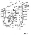
- FIG. 2 there is shown an actuating base 800 anchored to the floor using bolts 601-602 via anchor points (not visible) through anchor plates 603-604 (and another anchor plate which is not visible).
- Anchor plates 603-604 are fixed (e.g., welded) to a frame 605.
- the fixed portions 608a-b-c of the three linear actuators 606a-b-c are fixed to the frame 605 using bolts 607a-b.
- Actuators 606a-b-c may be thereby be removed and replaced.
- each of the actuators 606a-b-c define three linear axes which are substantially vertical; i.e., projecting upward from the gravity field even on inclined ground.
- the mobile portions 609a-b-c of the actuators 606a-b-c are connected to the seat base 702 using link members 600a-b-c.
- the fixed portion 608a of the front actuators 606a is more distant from the ground than the fixed portions 608b-c of the two rear actuators 606b-c. This results in a rearward inclination of the seat base 702 when the actuators 606a-b-c are in their reference position.
- the inclination of the seat base 702 is useful in providing a natural seating position to the user.
- all actuators are at the same level.
- linear actuators 606a-b-c can be replaced by any linear actuators powered by any type of energy such as electrical, hydraulic, pneumatic or thermal energy.
- controller 610 The function of controller 610 is to receive motion signals from an encoder (not shown) and interpret and-transform the motion signals into drive signals for driving each actuator 606a-b-c.
- the controller 610 may include functionalities related to the maintenance of the actuators 606a-b-c. This includes saving data in memory for download and analysis.
- the types of data include: time since installation, time since new, time under power, accelerations induced to the chair over time, number of movie representations shown, etc.
- Figs. 3 and 4 there are shown respectively a perspective exploded view of one of the link members 600a-b-c (i.e., 600) and a perspective view of the link members 600a-b-c (i.e., 600) of the actuating base of Fig. 2 .
- the link member 600 is for providing an interface between an actuator (i.e., one of actuators 606a, 606b, or 606c) and the seat base 702.
- the link member 600 has at least one translational degree of freedom and at least two rotational degrees of freedom.
- the link member 600 further comprises a joint member 714 to be attached to the actuator (i.e., one of actuators 606a, 606b, or 606c), a housing 716 to be attached to the seat base 702 and a slider 718 to be mounted on the joint member 714 and within the housing 716.
- the joint member 714 comprises a spherical surface 717 and a flange portion 715.
- the joint member may 714 may sometimes also be referred to as a ball.
- the housing 716 comprises a top cap 730 and a bottom cap 732 which are shown in more detail in Figs. 6 and 7 .
- the slider 718 is free to move in a translational plane within the housing 716. This provides at least one translational degree of freedom. Also, the slider 718 is free to slide on the spherical surface 717 of the joint member 714 and to pivot about a first axis and a second axis. This provides at least two rotational degrees of freedom.
- the slider 719 is free to move in more than one direction of the translational plane within the housing 716, thereby providing at least two translational degrees of freedom.
- the slider 718 is free to move in a translational plane within the housing 716 along a front-rear axis and left-right axis, thereby providing two translational degrees of freedom. Furthermore, the slider 718 is free to slide on the joint member 714 and to pivot about a pitch axis and a roll axis, thereby providing two rotational degrees of freedom.
- the slider 718 is free to slide on the joint member and to pivot about a yaw (vertical) axis thereby providing a third rotational degree of degree of freedom.
- the link member 600 may generally provide the interface between any first part and second part which need to be interfaced with a translational degree of freedom and at least two rotational degrees of freedom.
- the link member 600 can be installed in any other orientation. That is, the housing 716 can be attached to the actuator 606 while the joint member 714 can be attached to the seat base 702.
- the link member 600 can be installed generally vertically; that is, for example, between a seat back and another substantially vertical surface.
- a joint fastening member 722 ( Fig. 10 ) may be inserted through a hole 720 in the joint member 714 for attaching the joint member 714 to the actuator 606 ( Fig. 2 ).
- the hole 720 has a given depth determined by the type of application in which the link member 600 is used.
- Figs. 6 and 7 there is shown the top cap 730 and the bottom cap 732 of the housing 716 of link member 600 of Fig. 4 .
- the housing 716 is adapted to be attached to the seat base 702 ( Fig. 2 ).
- the top cap 730 and the bottom cap 732 of the housing 716 include substantially planar and circular sections 728 and 729.
- the bottom cap 732 also includes bumps 742 which create voids 744 therebetween.
- the top cap 730 may comprise a similar configuration of bumps and voids. This configuration facilitates the sliding of the slider 718 between the top cap 730 and the bottom cap 732.
- Fig. 8 there is shown a perspective view of the slider 718 of the link member 600 of Fig. 4 .
- the slider 718 is to be mounted on the joint member 714 and within the housing 716 ( Fig. 4 ).
- the slider 718 includes a substantially planar slider section 724 and a substantially concave section 726.
- the substantially planar slider section 724 of the slider 718 is adapted to move in the translational plane within the housing 716 between the substantially planar and circular sections 728 and 729 of housing 716.
- the substantially planar slider section 724 is well adapted to provide two translational degrees of freedom discussed above. A person skilled in the art will understand that other shapes would be appropriate for achieving this function. According to an embodiment where only one translational degree of freedom is required, a planar rectangular section could be appropriate.
- the substantially concave section 726 of the slider 718 is adapted to receive the joint member 714. It is to be noted that the substantially planar slider section 724 of the slider 718 defines a linear plane x-y ( Fig. 8A ), where the joint member 714 may be centered with the linear plane x-y of the substantially concave section 726 of the slider 718.
- the slider includes three arch portions 734 in the substantially planar slider section 724.
- the arch portions 734 are equally spaced along the periphery of the substantially planar slider section 724 of the slider 718.
- the utility of the arch portions 734 are discussed below.
- the configuration of the arch portions could be specifically unequally spaced to provide a specific alignment of the translational degree of freedom. This would be useful in embodiments where one translational degree of freedom is necessary along the substantially planar slider section 724.
- the substantially planar slider section 724 of the slider 718 defines a linear plane and the joint member 714 is centered within the linear plane such that the translational and rotational axes cross at the same point.
- Fig. 8A also shows a joint fastening member 722 which may be used for attaching the joint member 714 to the actuator 606 (see Fig. 10 ).
- the joint fastening member 722 may comprise, without limitations, one of a screw, a bolt, a shoulder screw, a pin, a cap screw, a socket cap screw, an eye bolt or a stud.
- joint fastening member 722 allows for vertical movement such as with a shoulder screw
- a third translational degree of freedom is provided. This degree of freedom allows for slight movement of the mobile portion 609 of the actuator 606 relative to the joint member 714.
- joint member 714 comprises a flange portion 715 which may be larger than mobile portion 609 to be supported by the fixed portion 608. This provides the advantage of reducing the load on the mobile portion 609 when actuator 606 is at its lowest position.
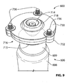
- Figs. 9 and 10 there are respectively shown a perspective view and an exploded perspective view of the link member 600 interfaced with an actuator 606.
- the link member 600 is for providing an interface between the actuator 606 and the seat base 702 ( Fig. 2 ). Also, the link member 600 has at least one translational degree of freedom and at least one rotational degree of freedom.
- the link member 600 further comprises a joint member 714 to be attached to the actuator 606, a housing 716 to be attached to the seat base 702 and a slider 718 to be mounted on the joint member 714 and within the housing 716.
- Figs. 9 and 10 there is shown the joint member 714, which includes a hole 720 through which a joint fastening member 722 may be inserted for attaching the joint member 714 to the actuator 606.
- the link member 600 further comprises seat fastening members 736 for attaching the housing 716 to the seat base 702 (see Fig. 2 ).
- the arch portions 734 and the corresponding housing openings 738 and 739 are adapted to admit the seat fastening members 736 for attaching the housing 716, i.e., the top cap 730 and the bottom cap 732, to the seat base 702.
- the seat fastening members 736 may comprise, without limitations, at least one of screws, bolts, shoulder screws, pins, cap screws, socket cap screws, eye bolts and studs.
- a sleeve 740 is provided for each one of the seat fastening members 736.
Landscapes
- Engineering & Computer Science (AREA)
- General Engineering & Computer Science (AREA)
- Mechanical Engineering (AREA)
- Health & Medical Sciences (AREA)
- Dentistry (AREA)
- General Health & Medical Sciences (AREA)
- Chairs For Special Purposes, Such As Reclining Chairs (AREA)
- Pivots And Pivotal Connections (AREA)
- Seats For Vehicles (AREA)
Description
- This description relates to the field of motion-enabled chairs. More particularly, this description relates to actuation of movie theatre seats.
- Prior art systems (e.g.
US2010/0090507 A1 ) include motion simulators and motion chairs used in homes, in video game arcades and in attraction park rides. - There is a need to introduce the technology of providing motion in seats installed in movie theatres. In the context of a movie theatre, restrictions relative to the space occupied by each individual seat are present and need to be overcome.
- According to the invention, there is provided a link member as claimed in claim 1.
- Preferred features of the invention are set out in the dependent claims.
- Further features and advantages of the present disclosure will become apparent from the following detailed description, taken in combination with the appended drawings, in which:
-
Fig. 1 is a perspective view of a chair according to an embodiment; -
Fig. 2 is a perspective view of an actuated base according to another embodiment; -
Fig. 3 is a perspective exploded view of a link member according to another embodiment and used with the actuated base ofFig. 2 ; -
Fig. 4 is a perspective view of a link member ofFig. 3 ; -
Fig. 5 is a perspective view of a joint member of the link member ofFig. 3 ; -
Fig. 5A is a side view of a joint member ofFig. 5 ; -
Fig. 6 is a perspective view of a top cap of a housing of the link member ofFig. 3 ; -
Fig. 7 is a perspective view of a bottom cap of a housing of the link member ofFig. 3 ; -
Fig. 8 is a perspective view of a slider of the link member ofFig. 3 ; -
Fig. 8A is a partial cut-out side view of the link member ofFig. 8 ; -
Fig. 9 is a perspective view of the link member ofFig. 3 interfaced with an actuator according to an embodiment; and -
Fig. 10 is an exploded perspective view of the link member ofFig. 3 interfaced with an actuator. - It will be noted that throughout the appended drawings, like features are identified by like reference numerals.
- Referring to the drawings, and more particularly to
Figs. 1 and2 , an actuated movie chair 100 (Fig. 1 ) is shown. The base 800 (Fig. 2 ) of thechair 100 lies on the ground and is covered by aprotective cover 101. The seating portion of thechair 100 is very similar to a standard movie chair or seat and comprises aseat base 102, abackrest 103 and armrests 104-105. Although thechair 100 shown inFig. 1 is designed for one user / movie viewer, it is understood that the concepts described herein extend to multi-user chair as well. - Between the
protective cover 101 and theseat base 102 there may be a protection skirt (not shown) for preventing users from injury while viewing a moving which comprising motion effects. According to an embodiment, the terms "protective cover" includes the protection skirt. The protection skirt is horizontally wrinkled and made of flexible material to adjust itself during the actuating (movement of the chair). - Below the
right armrest 104, acontrol panel 107 is accessible to the user for controlling the intensity (e.g., the amplitude range of theactuators 606a-b-c) of the motion effect inducing in thechair 100. Some of the options (i.e., modes of operation) include "Off' (i.e., no motion), "Light" (i.e., reduced motion), "Normal" (i.e., regular motion), "Heavy" (i.e., maximum motion), "Discreet" (i.e., fully controllable motion level between "Off" and "Heavy"), and "Automatic". Optionally, a vibration signal, a sound signal or light signal is provided to the user to indicate in which mode of operation or at which intensity level thechair 100 is operating. - In the "Automatic" mode, the
chair 100 uses a sensor (not shown) to detect a characteristic of the user (e.g., weight) and, based on the characteristic, determines the setting for the level of motion that will be induced in thechair 100. The sensor function can be achieved by a combination of feedback through one ormore actuators 606a-b-c and software algorithm hosted in the processor (not shown) of thecontroller 610. The weight sensor function can also be achieved by using a separate sensor 611 (seeFig. 2 ) installed on thechair 100.Sensor 611 is in communication (wired or wireless) with thecontroller 610 to determine, using a software algorithm, a characteristic of the user. Thecontrol panel 107 is therefore in communication with thecontroller 610. - Now referring to
Fig. 2 , there is shown anactuating base 800 anchored to the floor using bolts 601-602 via anchor points (not visible) through anchor plates 603-604 (and another anchor plate which is not visible). Anchor plates 603-604 are fixed (e.g., welded) to aframe 605. Thefixed portions 608a-b-c of the threelinear actuators 606a-b-c are fixed to theframe 605 usingbolts 607a-b.Actuators 606a-b-c may be thereby be removed and replaced. During use of the chair, there is no relative movement between thefixed portions 608a-b-c of the threelinear actuators 606a-b-c and the frame. - The linear directions of movement of each of the
actuators 606a-b-c define three linear axes which are substantially vertical; i.e., projecting upward from the gravity field even on inclined ground. - The
mobile portions 609a-b-c of theactuators 606a-b-c are connected to theseat base 702 usinglink members 600a-b-c. In the embodiment shown inFig. 2 , thefixed portion 608a of thefront actuators 606a is more distant from the ground than thefixed portions 608b-c of the tworear actuators 606b-c. This results in a rearward inclination of theseat base 702 when theactuators 606a-b-c are in their reference position. The inclination of theseat base 702 is useful in providing a natural seating position to the user. According to another embodiment, all actuators are at the same level. - The person skilled in the art will understand that
linear actuators 606a-b-c can be replaced by any linear actuators powered by any type of energy such as electrical, hydraulic, pneumatic or thermal energy. - The function of
controller 610 is to receive motion signals from an encoder (not shown) and interpret and-transform the motion signals into drive signals for driving eachactuator 606a-b-c. - The
controller 610, or another electronic device with a processor and memory (not shown), may include functionalities related to the maintenance of theactuators 606a-b-c. This includes saving data in memory for download and analysis. The types of data include: time since installation, time since new, time under power, accelerations induced to the chair over time, number of movie representations shown, etc. - Now referring to
Figs. 3 and4 , there are shown respectively a perspective exploded view of one of thelink members 600a-b-c (i.e., 600) and a perspective view of thelink members 600a-b-c (i.e., 600) of the actuating base ofFig. 2 . Thelink member 600 is for providing an interface between an actuator (i.e., one ofactuators seat base 702. Also, thelink member 600 has at least one translational degree of freedom and at least two rotational degrees of freedom. - The
link member 600 further comprises ajoint member 714 to be attached to the actuator (i.e., one ofactuators housing 716 to be attached to theseat base 702 and aslider 718 to be mounted on thejoint member 714 and within thehousing 716. Thejoint member 714 comprises aspherical surface 717 and aflange portion 715. The joint member may 714 may sometimes also be referred to as a ball. According to an embodiment, thehousing 716 comprises atop cap 730 and abottom cap 732 which are shown in more detail inFigs. 6 and 7 . - The
slider 718 is free to move in a translational plane within thehousing 716. This provides at least one translational degree of freedom. Also, theslider 718 is free to slide on thespherical surface 717 of thejoint member 714 and to pivot about a first axis and a second axis. This provides at least two rotational degrees of freedom. - Generally, the slider 719 is free to move in more than one direction of the translational plane within the
housing 716, thereby providing at least two translational degrees of freedom. - According to the embodiment shown in
Figs. 3 and4 , it is to be noted that theslider 718 is free to move in a translational plane within thehousing 716 along a front-rear axis and left-right axis, thereby providing two translational degrees of freedom. Furthermore, theslider 718 is free to slide on thejoint member 714 and to pivot about a pitch axis and a roll axis, thereby providing two rotational degrees of freedom. - According to an embodiment, the
slider 718 is free to slide on the joint member and to pivot about a yaw (vertical) axis thereby providing a third rotational degree of degree of freedom. - It should be noted that although the
link member 600 is shown in an application where it is the interface between aseat base 702 and an actuator, thelink member 600 may generally provide the interface between any first part and second part which need to be interfaced with a translational degree of freedom and at least two rotational degrees of freedom. Furthermore, it is understood that thelink member 600 can be installed in any other orientation. That is, thehousing 716 can be attached to theactuator 606 while thejoint member 714 can be attached to theseat base 702. In other applications, thelink member 600 can be installed generally vertically; that is, for example, between a seat back and another substantially vertical surface. - Now referring to
Figs. 5 and 5A , there is shown a perspective view of ajoint member 714 oflink member 600 ofFig. 4 . In use, a joint fastening member 722 (Fig. 10 ) may be inserted through ahole 720 in thejoint member 714 for attaching thejoint member 714 to the actuator 606 (Fig. 2 ). Thehole 720 has a given depth determined by the type of application in which thelink member 600 is used. - Now referring to
Figs. 6 and 7 respectively, there is shown thetop cap 730 and thebottom cap 732 of thehousing 716 oflink member 600 ofFig. 4 . Thehousing 716 is adapted to be attached to the seat base 702 (Fig. 2 ). Thetop cap 730 and thebottom cap 732 of thehousing 716 include substantially planar andcircular sections bottom cap 732 also includesbumps 742 which createvoids 744 therebetween. Although not shown, thetop cap 730 may comprise a similar configuration of bumps and voids. This configuration facilitates the sliding of theslider 718 between thetop cap 730 and thebottom cap 732. - Now referring to
Fig. 8 , there is shown a perspective view of theslider 718 of thelink member 600 ofFig. 4 . Theslider 718 is to be mounted on thejoint member 714 and within the housing 716 (Fig. 4 ). Theslider 718 includes a substantiallyplanar slider section 724 and a substantiallyconcave section 726. The substantiallyplanar slider section 724 of theslider 718 is adapted to move in the translational plane within thehousing 716 between the substantially planar andcircular sections housing 716. - The substantially
planar slider section 724 is well adapted to provide two translational degrees of freedom discussed above. A person skilled in the art will understand that other shapes would be appropriate for achieving this function. According to an embodiment where only one translational degree of freedom is required, a planar rectangular section could be appropriate. - The substantially
concave section 726 of theslider 718 is adapted to receive thejoint member 714. It is to be noted that the substantiallyplanar slider section 724 of theslider 718 defines a linear plane x-y (Fig. 8A ), where thejoint member 714 may be centered with the linear plane x-y of the substantiallyconcave section 726 of theslider 718. - Referring to
Fig. 8 , the slider includes threearch portions 734 in the substantiallyplanar slider section 724. Thearch portions 734 are equally spaced along the periphery of the substantiallyplanar slider section 724 of theslider 718. The utility of thearch portions 734 are discussed below. In other embodiments, the configuration of the arch portions could be specifically unequally spaced to provide a specific alignment of the translational degree of freedom. This would be useful in embodiments where one translational degree of freedom is necessary along the substantiallyplanar slider section 724. - Referring to
Fig. 8A , the substantiallyplanar slider section 724 of theslider 718 defines a linear plane and thejoint member 714 is centered within the linear plane such that the translational and rotational axes cross at the same point. -
Fig. 8A also shows ajoint fastening member 722 which may be used for attaching thejoint member 714 to the actuator 606 (seeFig. 10 ). Thejoint fastening member 722 may comprise, without limitations, one of a screw, a bolt, a shoulder screw, a pin, a cap screw, a socket cap screw, an eye bolt or a stud. - In an embodiment where the
joint fastening member 722 allows for vertical movement such as with a shoulder screw, a third translational degree of freedom is provided. This degree of freedom allows for slight movement of themobile portion 609 of theactuator 606 relative to thejoint member 714. It should be noted thatjoint member 714 comprises aflange portion 715 which may be larger thanmobile portion 609 to be supported by the fixedportion 608. This provides the advantage of reducing the load on themobile portion 609 whenactuator 606 is at its lowest position. - Now referring to
Figs. 9 and10 , there are respectively shown a perspective view and an exploded perspective view of thelink member 600 interfaced with anactuator 606. Thelink member 600 is for providing an interface between the actuator 606 and the seat base 702 (Fig. 2 ). Also, thelink member 600 has at least one translational degree of freedom and at least one rotational degree of freedom. - The
link member 600 further comprises ajoint member 714 to be attached to theactuator 606, ahousing 716 to be attached to theseat base 702 and aslider 718 to be mounted on thejoint member 714 and within thehousing 716. - In
Figs. 9 and10 , there is shown thejoint member 714, which includes ahole 720 through which ajoint fastening member 722 may be inserted for attaching thejoint member 714 to theactuator 606. - According to an embodiment, the
link member 600 further comprisesseat fastening members 736 for attaching thehousing 716 to the seat base 702 (seeFig. 2 ). There is also shown that thearch portions 734 and thecorresponding housing openings seat fastening members 736 for attaching thehousing 716, i.e., thetop cap 730 and thebottom cap 732, to theseat base 702. Theseat fastening members 736 may comprise, without limitations, at least one of screws, bolts, shoulder screws, pins, cap screws, socket cap screws, eye bolts and studs. Asleeve 740 is provided for each one of theseat fastening members 736. - While preferred embodiments of the invention have been described above and illustrated in the accompanying drawings, it will be evident to those skilled in the art that modifications may be made therein without departing from the scope of the invention, defined by the appended claims.
Claims (15)
- A link member (600) for providing an interface between a first part and a second part, the link member (600) has a translational degree of freedom and at least two rotational degrees of freedom, the link member comprising:a joint member (714) having a spherical surface, the joint member for attachment to the first part;a housing (716) for attachment to the second part; anda slider (718) mounted on the spherical surface and within the housing (716);wherein the slider (718) is free to move in a direction of a translational plane within the housing (716) thereby providing the translational degree of freedom and further wherein the slider (718) is free to slide on the spherical surface and to pivot about a first axis and a second axis thereby providing the two rotational degrees of freedom.
- The link member of claim 1, wherein a crossing of the first axis and the second axis is within the translational plane.
- The link member according to any of the claims 1 and 2, wherein said first and second parts are an actuator and a seat base,
wherein the link member has at least one translational degree of freedom and at least two rotational degrees of freedom, the link member comprising:a joint member having a spherical surface, the joint member for attachment to one of the actuator and the seat base;a housing for attachment to the other one of the actuator and the seat base; anda slider mounted on the spherical surface and within the housing;and wherein the slider is free to move in a direction of a translational plane within the housing thereby providing the at least one translational degree of freedom and further wherein the slider is free to slide on the spherical surface and to pivot about a first axis and a second axis thereby providing the at least two rotational degrees of freedom. - The link member of claim 3, wherein the first axis provides pitch movement and the second axis provides roll movement to the seat base.
- The link member of any of claims 3 and 4, wherein the slider is free to move in more than one direction of the translational plane within the housing, thereby providing at least two translational degrees of freedom.
- The link member of any of claims 3 to 5, further comprising a joint fastening member and wherein the joint member comprises a hole therethrough for inserting the joint fastening member used for attaching the joint member to one of the actuator and the seat base.
- The link member of claim 6, wherein the joint fastening member comprises one of a screw, a bolt, a shoulder screw, a pin, a cap screw, a socket cap screw, an eye bolt, and a stud.
- The link member of any of claims 6 and 7, wherein the hole has a given depth and the joint fastening member comprises a shoulder screw which is longer than the given depth thereby providing a third translational degree of freedom along the axial direction of the shoulder screw.
- The link member of any of claims 3 to 8, wherein the slider comprises a substantially planar slider section adapted to move in the translational plane within the housing.
- The link member of any of claims 3 to 9, wherein a crossing of the first axis and the second axis is within the translational plane.
- The link member of any of claims 3 to 10, wherein the housing comprises a top cap and a bottom cap.
- The link member of claim 11, wherein the top cap and the bottom cap each comprises a substantially planar cap section and wherein the slider comprises a substantially planar slider section adapted to slide between the top cap and the bottom cap.
- The link member of claim 12, wherein at least one of the substantially planar cap sections comprises a surface having voids for facilitating the sliding between the top cap and the bottom cap.
- The link member of any of claims 3 to 13, further comprising at least one seat fastening member for attaching the housing to the other of the actuator and the seat base wherein the housing comprises at least one housing opening which is adapted to admit the at least one seat fastening member therethrough.
- The link member of claim 14, wherein the slider comprises at least one slider opening which corresponds to the at least one housing opening and which is adapted to allow clearance for the at least one fastening member:
Applications Claiming Priority (2)
| Application Number | Priority Date | Filing Date | Title |
|---|---|---|---|
| US13/070,332 US8657376B2 (en) | 2008-10-11 | 2011-03-23 | Link member for motion-enabled movie theatre chair |
| PCT/CA2012/000257 WO2012126093A1 (en) | 2011-03-23 | 2012-03-21 | Link member for motion-enabled movie theatre chair |
Publications (3)
| Publication Number | Publication Date |
|---|---|
| EP2689152A1 EP2689152A1 (en) | 2014-01-29 |
| EP2689152A4 EP2689152A4 (en) | 2014-08-27 |
| EP2689152B1 true EP2689152B1 (en) | 2015-12-09 |
Family
ID=46878574
Family Applications (1)
| Application Number | Title | Priority Date | Filing Date |
|---|---|---|---|
| EP12761436.0A Active EP2689152B1 (en) | 2011-03-23 | 2012-03-21 | Link member for motion-enabled movie theatre chair |
Country Status (4)
| Country | Link |
|---|---|
| US (1) | US8657376B2 (en) |
| EP (1) | EP2689152B1 (en) |
| CA (1) | CA2864912A1 (en) |
| WO (1) | WO2012126093A1 (en) |
Families Citing this family (15)
| Publication number | Priority date | Publication date | Assignee | Title |
|---|---|---|---|---|
| CN102530773A (en) * | 2011-10-27 | 2012-07-04 | 北京航天计量测试技术研究所 | Five-DOF (degree of freedoms) hinge for suspending hoistable platform |
| CN102652877A (en) * | 2011-11-22 | 2012-09-05 | 上海华博信息服务有限公司 | Dynamic seat with adjustable action strength and control method thereof |
| DE102011119392A1 (en) * | 2011-11-24 | 2013-05-29 | Knorr-Bremse Systeme für Nutzfahrzeuge GmbH | Adjustable mounting device for sensors |
| CN102652880A (en) * | 2011-12-12 | 2012-09-05 | 上海华博信息服务有限公司 | Adjustable dynamic seat capable of memorizing sitting posture and application thereof |
| KR101154143B1 (en) | 2012-02-20 | 2012-06-14 | 씨제이포디플렉스 주식회사 | System for controlling seat effect for facility of showing pictures |
| TWM442183U (en) * | 2012-05-07 | 2012-12-01 | Injoy Motion Corp | Decoupling two-axis motion platform |
| KR101377594B1 (en) * | 2013-02-20 | 2014-03-25 | 주식회사 모션디바이스 | Motion simulator |
| CH710154B1 (en) | 2014-09-26 | 2018-03-29 | Sitag Ag | Seating device. |
| CN105342197B (en) * | 2015-11-30 | 2018-02-02 | 永艺家具股份有限公司 | A kind of rotating mechanism and writing device for training chair |
| KR102750573B1 (en) | 2016-12-14 | 2025-01-06 | 시안 키스퓨처 네트워크 테크놀로지 컴퍼니 리미티드 | VR motion control method, multidimensional motion platform and thrust universal joint bearing |
| CN106647820B (en) * | 2016-12-14 | 2020-04-10 | 西安可视可觉网络科技有限公司 | Motion platform capable of realizing autorotation and free swinging based on hoisting bearing |
| CN106974461B (en) * | 2017-03-20 | 2023-09-12 | 歌尔科技有限公司 | Multi freedom VR seat drive arrangement and VR seat |
| CN107008020A (en) * | 2017-04-04 | 2017-08-04 | 江西制造职业技术学院 | A kind of multidimensional seat equipment driven by Three Degree Of Freedom translation platform |
| DE102017208242A1 (en) * | 2017-05-16 | 2018-11-22 | Stabilus Gmbh | Seat device with seat parameter recognition |
| FI130036B (en) * | 2021-05-20 | 2022-12-30 | Lappeenrannan Lahden Teknillinen Yliopisto Lut | Four-degree-of-freedom kinematic structure |
Family Cites Families (29)
| Publication number | Priority date | Publication date | Assignee | Title |
|---|---|---|---|---|
| US2441401A (en) * | 1946-08-06 | 1948-05-11 | Ward E Eckstein | Toy aircraft |
| US3645011A (en) | 1969-02-17 | 1972-02-29 | Melpar Inc | Motion system with three reciprocating actuators for flight simulation |
| US3577655A (en) | 1969-05-19 | 1971-05-04 | Singer General Precision | Motion simulator |
| US3923300A (en) | 1973-04-24 | 1975-12-02 | Antonio Tanus | Theater chair automatically movable by remote control |
| US4066256A (en) | 1975-11-17 | 1978-01-03 | Future General Corporation | Amusement ride |
| NL8802827A (en) | 1988-11-16 | 1990-06-18 | Itrec Bv | EARTHQUAKE SIMULATOR FOR A FUN PARK. |
| US5022708A (en) | 1989-11-16 | 1991-06-11 | Creative Presentations, Inc. | Mechanical seat apparatus for simulating motion |
| US5022384A (en) | 1990-05-14 | 1991-06-11 | Capitol Systems | Vibrating/massage chair |
| US5605462A (en) | 1991-07-12 | 1997-02-25 | Denne Developments Ltd. | Motion imparting apparatus |
| DE4208116C2 (en) * | 1992-03-13 | 1995-08-03 | Link Waldemar Gmbh Co | Intervertebral disc prosthesis |
| GB2279316B (en) * | 1993-06-08 | 1997-03-26 | Compacific Engineering Pte Lim | Multi-tier jack motion system |
| US5496220A (en) | 1994-06-02 | 1996-03-05 | Brad Engstrand | Sensory simulator |
| US6094180A (en) | 1996-04-05 | 2000-07-25 | Fakespace, Inc. | Gimbal-mounted virtual reality display system |
| US5678889A (en) | 1996-04-09 | 1997-10-21 | Purcell, Jr.; Joseph William | Moveable theater seats |
| NL1004551C2 (en) | 1996-11-18 | 1998-05-19 | Rpi Advanced Technology Group | Chair. |
| US5954508A (en) | 1997-08-20 | 1999-09-21 | Interactive Motion Systems | Portable and compact motion simulator |
| US6162058A (en) | 1998-02-03 | 2000-12-19 | Kumyang Co., Ltd. | Motion base device for simulators |
| US6413090B1 (en) | 1998-03-30 | 2002-07-02 | Hitachi, Ltd. | VR motion base control apparatus and it's supporting structure |
| JP4672094B2 (en) | 1999-01-22 | 2011-04-20 | ソニー株式会社 | Image processing apparatus and method, and recording medium |
| US6113500A (en) * | 1999-03-18 | 2000-09-05 | Cinema Ride, Inc. | 3-D simulator ride |
| US6733293B2 (en) | 2001-01-26 | 2004-05-11 | Provision Entertainment, Inc. | Personal simulator |
| KR20030056754A (en) | 2001-12-28 | 2003-07-04 | (주)비전테크시스템 | simulator for virtual reality experience |
| US20050277092A1 (en) | 2004-06-01 | 2005-12-15 | Thong-Shing Hwang | Motion platform device for spatial disorientation simulation |
| US7717711B2 (en) | 2004-09-02 | 2010-05-18 | Sean MacDonald | Collapsible motion platform |
| US7361192B2 (en) * | 2005-04-22 | 2008-04-22 | Doty Keith L | Spinal disc prosthesis and methods of use |
| US20070135551A1 (en) * | 2005-12-12 | 2007-06-14 | Nissin Chemical Industry Co., Ltd. | Coating composition and vehicle interior material |
| US20080009776A1 (en) | 2006-03-24 | 2008-01-10 | Juvent Inc. | Apparatus and method for monitoring and controlling the transmissibility of mechanical vibration energy during dynamic motion therapy |
| ITMI20061000A1 (en) | 2006-05-22 | 2007-11-23 | Milano Politecnico | ELASTIC COUPLING WITH SPHERICAL HINGE TRANSLATOR AND SENSOR OF FORCES AND MOMENTS PERFECTED WITH THIS JOINT |
| US7934773B2 (en) | 2008-10-11 | 2011-05-03 | D-Box Technologies Inc. | Motion-enabled movie theater seat |
-
2011
- 2011-03-23 US US13/070,332 patent/US8657376B2/en active Active
-
2012
- 2012-03-21 CA CA2864912A patent/CA2864912A1/en not_active Abandoned
- 2012-03-21 WO PCT/CA2012/000257 patent/WO2012126093A1/en not_active Ceased
- 2012-03-21 EP EP12761436.0A patent/EP2689152B1/en active Active
Also Published As
| Publication number | Publication date |
|---|---|
| CA2864912A1 (en) | 2013-09-27 |
| US8657376B2 (en) | 2014-02-25 |
| EP2689152A4 (en) | 2014-08-27 |
| US20110170945A1 (en) | 2011-07-14 |
| EP2689152A1 (en) | 2014-01-29 |
| WO2012126093A1 (en) | 2012-09-27 |
Similar Documents
| Publication | Publication Date | Title |
|---|---|---|
| US8657376B2 (en) | Link member for motion-enabled movie theatre chair | |
| US7934773B2 (en) | Motion-enabled movie theater seat | |
| US10967773B2 (en) | Haptic system: recline activation control | |
| US6224380B1 (en) | Portable and compact motion simulator with a single degree-of-freedom | |
| US9812045B2 (en) | Large projection screen image device with seesaw structure for virtual reality | |
| KR101755128B1 (en) | Virtual Reality Theater Structure | |
| CN105473888A (en) | Vehicle seat or vehicle cab with a suspension system, and utility vehicle | |
| WO2006130723A3 (en) | Magnetic haptic feedback systems and methods for virtual reality environments | |
| CN107625324A (en) | A kind of chair bottom and office chair | |
| US20190310711A1 (en) | Method and system for sensory simulation in virtual reality to enhance immersion | |
| GB2475977A (en) | Height and rotatably adjustable support device for a display | |
| KR101769591B1 (en) | Magnetic levitation supporting apparatus | |
| KR20180007588A (en) | Electromotive tilt system for touchscreen monitor | |
| KR20170065767A (en) | rotation angle automatic control system of display and the control method | |
| JP2016032621A (en) | Chair capable of checking seating state | |
| KR102059236B1 (en) | Virtual real machine for flying bird | |
| CN116714529A (en) | Screen assembly and vehicle with adjustable screen angle | |
| KR20130080591A (en) | Driving device indication direction of which is controlled freely | |
| JP2005279064A (en) | Chair | |
| US11994272B2 (en) | Lighting assembly and illumination system having a lighting assembly | |
| KR200487417Y1 (en) | Earthquake experience apparatus based on 4-axis control | |
| KR102027051B1 (en) | System for Kinetic Wall | |
| KR20140111804A (en) | Motion base | |
| KR20110133920A (en) | Motion simulator | |
| US20120069496A1 (en) | System and method for device stabilization |
Legal Events
| Date | Code | Title | Description |
|---|---|---|---|
| PUAI | Public reference made under article 153(3) epc to a published international application that has entered the european phase |
Free format text: ORIGINAL CODE: 0009012 |
|
| 17P | Request for examination filed |
Effective date: 20131010 |
|
| AK | Designated contracting states |
Kind code of ref document: A1 Designated state(s): AL AT BE BG CH CY CZ DE DK EE ES FI FR GB GR HR HU IE IS IT LI LT LU LV MC MK MT NL NO PL PT RO RS SE SI SK SM TR |
|
| DAX | Request for extension of the european patent (deleted) | ||
| A4 | Supplementary search report drawn up and despatched |
Effective date: 20140724 |
|
| RIC1 | Information provided on ipc code assigned before grant |
Ipc: A47C 31/00 20060101ALI20140718BHEP Ipc: A47C 1/12 20060101ALI20140718BHEP Ipc: F16C 11/06 20060101AFI20140718BHEP Ipc: A63J 25/00 20090101ALI20140718BHEP Ipc: A47C 7/62 20060101ALI20140718BHEP Ipc: A63F 11/00 20060101ALI20140718BHEP |
|
| RIC1 | Information provided on ipc code assigned before grant |
Ipc: A47C 31/00 20060101ALI20150415BHEP Ipc: A47C 1/12 20060101ALI20150415BHEP Ipc: F16C 29/02 20060101ALI20150415BHEP Ipc: A47C 15/00 20060101ALI20150415BHEP Ipc: A63J 25/00 20090101ALI20150415BHEP Ipc: A47C 7/00 20060101ALI20150415BHEP Ipc: F16C 11/06 20060101AFI20150415BHEP Ipc: A47C 7/62 20060101ALI20150415BHEP Ipc: A63F 11/00 20060101ALI20150415BHEP Ipc: A47C 7/68 20060101ALI20150415BHEP Ipc: A63G 31/16 20060101ALI20150415BHEP |
|
| GRAP | Despatch of communication of intention to grant a patent |
Free format text: ORIGINAL CODE: EPIDOSNIGR1 |
|
| INTG | Intention to grant announced |
Effective date: 20150610 |
|
| GRAS | Grant fee paid |
Free format text: ORIGINAL CODE: EPIDOSNIGR3 |
|
| GRAA | (expected) grant |
Free format text: ORIGINAL CODE: 0009210 |
|
| AK | Designated contracting states |
Kind code of ref document: B1 Designated state(s): AL AT BE BG CH CY CZ DE DK EE ES FI FR GB GR HR HU IE IS IT LI LT LU LV MC MK MT NL NO PL PT RO RS SE SI SK SM TR |
|
| REG | Reference to a national code |
Ref country code: GB Ref legal event code: FG4D |
|
| REG | Reference to a national code |
Ref country code: AT Ref legal event code: REF Ref document number: 764715 Country of ref document: AT Kind code of ref document: T Effective date: 20151215 Ref country code: CH Ref legal event code: EP |
|
| REG | Reference to a national code |
Ref country code: IE Ref legal event code: FG4D |
|
| REG | Reference to a national code |
Ref country code: DE Ref legal event code: R096 Ref document number: 602012012946 Country of ref document: DE |
|
| REG | Reference to a national code |
Ref country code: FR Ref legal event code: PLFP Year of fee payment: 5 |
|
| REG | Reference to a national code |
Ref country code: LT Ref legal event code: MG4D |
|
| REG | Reference to a national code |
Ref country code: NL Ref legal event code: MP Effective date: 20151209 |
|
| PG25 | Lapsed in a contracting state [announced via postgrant information from national office to epo] |
Ref country code: NO Free format text: LAPSE BECAUSE OF FAILURE TO SUBMIT A TRANSLATION OF THE DESCRIPTION OR TO PAY THE FEE WITHIN THE PRESCRIBED TIME-LIMIT Effective date: 20160309 Ref country code: ES Free format text: LAPSE BECAUSE OF FAILURE TO SUBMIT A TRANSLATION OF THE DESCRIPTION OR TO PAY THE FEE WITHIN THE PRESCRIBED TIME-LIMIT Effective date: 20151209 Ref country code: LT Free format text: LAPSE BECAUSE OF FAILURE TO SUBMIT A TRANSLATION OF THE DESCRIPTION OR TO PAY THE FEE WITHIN THE PRESCRIBED TIME-LIMIT Effective date: 20151209 |
|
| REG | Reference to a national code |
Ref country code: AT Ref legal event code: MK05 Ref document number: 764715 Country of ref document: AT Kind code of ref document: T Effective date: 20151209 |
|
| PG25 | Lapsed in a contracting state [announced via postgrant information from national office to epo] |
Ref country code: FI Free format text: LAPSE BECAUSE OF FAILURE TO SUBMIT A TRANSLATION OF THE DESCRIPTION OR TO PAY THE FEE WITHIN THE PRESCRIBED TIME-LIMIT Effective date: 20151209 Ref country code: SE Free format text: LAPSE BECAUSE OF FAILURE TO SUBMIT A TRANSLATION OF THE DESCRIPTION OR TO PAY THE FEE WITHIN THE PRESCRIBED TIME-LIMIT Effective date: 20151209 Ref country code: GR Free format text: LAPSE BECAUSE OF FAILURE TO SUBMIT A TRANSLATION OF THE DESCRIPTION OR TO PAY THE FEE WITHIN THE PRESCRIBED TIME-LIMIT Effective date: 20160310 Ref country code: RS Free format text: LAPSE BECAUSE OF FAILURE TO SUBMIT A TRANSLATION OF THE DESCRIPTION OR TO PAY THE FEE WITHIN THE PRESCRIBED TIME-LIMIT Effective date: 20151209 Ref country code: NL Free format text: LAPSE BECAUSE OF FAILURE TO SUBMIT A TRANSLATION OF THE DESCRIPTION OR TO PAY THE FEE WITHIN THE PRESCRIBED TIME-LIMIT Effective date: 20151209 Ref country code: LV Free format text: LAPSE BECAUSE OF FAILURE TO SUBMIT A TRANSLATION OF THE DESCRIPTION OR TO PAY THE FEE WITHIN THE PRESCRIBED TIME-LIMIT Effective date: 20151209 |
|
| PG25 | Lapsed in a contracting state [announced via postgrant information from national office to epo] |
Ref country code: IS Free format text: LAPSE BECAUSE OF FAILURE TO SUBMIT A TRANSLATION OF THE DESCRIPTION OR TO PAY THE FEE WITHIN THE PRESCRIBED TIME-LIMIT Effective date: 20151209 |
|
| PG25 | Lapsed in a contracting state [announced via postgrant information from national office to epo] |
Ref country code: CZ Free format text: LAPSE BECAUSE OF FAILURE TO SUBMIT A TRANSLATION OF THE DESCRIPTION OR TO PAY THE FEE WITHIN THE PRESCRIBED TIME-LIMIT Effective date: 20151209 Ref country code: IT Free format text: LAPSE BECAUSE OF FAILURE TO SUBMIT A TRANSLATION OF THE DESCRIPTION OR TO PAY THE FEE WITHIN THE PRESCRIBED TIME-LIMIT Effective date: 20151209 |
|
| PG25 | Lapsed in a contracting state [announced via postgrant information from national office to epo] |
Ref country code: AT Free format text: LAPSE BECAUSE OF FAILURE TO SUBMIT A TRANSLATION OF THE DESCRIPTION OR TO PAY THE FEE WITHIN THE PRESCRIBED TIME-LIMIT Effective date: 20151209 Ref country code: IS Free format text: LAPSE BECAUSE OF FAILURE TO SUBMIT A TRANSLATION OF THE DESCRIPTION OR TO PAY THE FEE WITHIN THE PRESCRIBED TIME-LIMIT Effective date: 20160409 Ref country code: RO Free format text: LAPSE BECAUSE OF FAILURE TO SUBMIT A TRANSLATION OF THE DESCRIPTION OR TO PAY THE FEE WITHIN THE PRESCRIBED TIME-LIMIT Effective date: 20151209 Ref country code: BE Free format text: LAPSE BECAUSE OF NON-PAYMENT OF DUE FEES Effective date: 20160331 Ref country code: EE Free format text: LAPSE BECAUSE OF FAILURE TO SUBMIT A TRANSLATION OF THE DESCRIPTION OR TO PAY THE FEE WITHIN THE PRESCRIBED TIME-LIMIT Effective date: 20151209 Ref country code: PT Free format text: LAPSE BECAUSE OF FAILURE TO SUBMIT A TRANSLATION OF THE DESCRIPTION OR TO PAY THE FEE WITHIN THE PRESCRIBED TIME-LIMIT Effective date: 20160411 Ref country code: SM Free format text: LAPSE BECAUSE OF FAILURE TO SUBMIT A TRANSLATION OF THE DESCRIPTION OR TO PAY THE FEE WITHIN THE PRESCRIBED TIME-LIMIT Effective date: 20151209 Ref country code: SK Free format text: LAPSE BECAUSE OF FAILURE TO SUBMIT A TRANSLATION OF THE DESCRIPTION OR TO PAY THE FEE WITHIN THE PRESCRIBED TIME-LIMIT Effective date: 20151209 |
|
| REG | Reference to a national code |
Ref country code: DE Ref legal event code: R097 Ref document number: 602012012946 Country of ref document: DE |
|
| PLBE | No opposition filed within time limit |
Free format text: ORIGINAL CODE: 0009261 |
|
| STAA | Information on the status of an ep patent application or granted ep patent |
Free format text: STATUS: NO OPPOSITION FILED WITHIN TIME LIMIT |
|
| PG25 | Lapsed in a contracting state [announced via postgrant information from national office to epo] |
Ref country code: LU Free format text: LAPSE BECAUSE OF FAILURE TO SUBMIT A TRANSLATION OF THE DESCRIPTION OR TO PAY THE FEE WITHIN THE PRESCRIBED TIME-LIMIT Effective date: 20160321 Ref country code: MC Free format text: LAPSE BECAUSE OF FAILURE TO SUBMIT A TRANSLATION OF THE DESCRIPTION OR TO PAY THE FEE WITHIN THE PRESCRIBED TIME-LIMIT Effective date: 20151209 Ref country code: DK Free format text: LAPSE BECAUSE OF FAILURE TO SUBMIT A TRANSLATION OF THE DESCRIPTION OR TO PAY THE FEE WITHIN THE PRESCRIBED TIME-LIMIT Effective date: 20151209 Ref country code: PL Free format text: LAPSE BECAUSE OF FAILURE TO SUBMIT A TRANSLATION OF THE DESCRIPTION OR TO PAY THE FEE WITHIN THE PRESCRIBED TIME-LIMIT Effective date: 20151209 |
|
| REG | Reference to a national code |
Ref country code: CH Ref legal event code: PL |
|
| 26N | No opposition filed |
Effective date: 20160912 |
|
| PG25 | Lapsed in a contracting state [announced via postgrant information from national office to epo] |
Ref country code: SI Free format text: LAPSE BECAUSE OF FAILURE TO SUBMIT A TRANSLATION OF THE DESCRIPTION OR TO PAY THE FEE WITHIN THE PRESCRIBED TIME-LIMIT Effective date: 20151209 |
|
| REG | Reference to a national code |
Ref country code: IE Ref legal event code: MM4A |
|
| PG25 | Lapsed in a contracting state [announced via postgrant information from national office to epo] |
Ref country code: BE Free format text: LAPSE BECAUSE OF FAILURE TO SUBMIT A TRANSLATION OF THE DESCRIPTION OR TO PAY THE FEE WITHIN THE PRESCRIBED TIME-LIMIT Effective date: 20151209 |
|
| PG25 | Lapsed in a contracting state [announced via postgrant information from national office to epo] |
Ref country code: LI Free format text: LAPSE BECAUSE OF NON-PAYMENT OF DUE FEES Effective date: 20160331 Ref country code: IE Free format text: LAPSE BECAUSE OF NON-PAYMENT OF DUE FEES Effective date: 20160321 Ref country code: CH Free format text: LAPSE BECAUSE OF NON-PAYMENT OF DUE FEES Effective date: 20160331 |
|
| REG | Reference to a national code |
Ref country code: FR Ref legal event code: PLFP Year of fee payment: 6 |
|
| PG25 | Lapsed in a contracting state [announced via postgrant information from national office to epo] |
Ref country code: MT Free format text: LAPSE BECAUSE OF FAILURE TO SUBMIT A TRANSLATION OF THE DESCRIPTION OR TO PAY THE FEE WITHIN THE PRESCRIBED TIME-LIMIT Effective date: 20151209 |
|
| REG | Reference to a national code |
Ref country code: FR Ref legal event code: PLFP Year of fee payment: 7 |
|
| PG25 | Lapsed in a contracting state [announced via postgrant information from national office to epo] |
Ref country code: HU Free format text: LAPSE BECAUSE OF FAILURE TO SUBMIT A TRANSLATION OF THE DESCRIPTION OR TO PAY THE FEE WITHIN THE PRESCRIBED TIME-LIMIT; INVALID AB INITIO Effective date: 20120321 Ref country code: CY Free format text: LAPSE BECAUSE OF FAILURE TO SUBMIT A TRANSLATION OF THE DESCRIPTION OR TO PAY THE FEE WITHIN THE PRESCRIBED TIME-LIMIT Effective date: 20151209 |
|
| PG25 | Lapsed in a contracting state [announced via postgrant information from national office to epo] |
Ref country code: TR Free format text: LAPSE BECAUSE OF FAILURE TO SUBMIT A TRANSLATION OF THE DESCRIPTION OR TO PAY THE FEE WITHIN THE PRESCRIBED TIME-LIMIT Effective date: 20151209 Ref country code: HR Free format text: LAPSE BECAUSE OF FAILURE TO SUBMIT A TRANSLATION OF THE DESCRIPTION OR TO PAY THE FEE WITHIN THE PRESCRIBED TIME-LIMIT Effective date: 20151209 Ref country code: MK Free format text: LAPSE BECAUSE OF FAILURE TO SUBMIT A TRANSLATION OF THE DESCRIPTION OR TO PAY THE FEE WITHIN THE PRESCRIBED TIME-LIMIT Effective date: 20151209 Ref country code: MT Free format text: LAPSE BECAUSE OF FAILURE TO SUBMIT A TRANSLATION OF THE DESCRIPTION OR TO PAY THE FEE WITHIN THE PRESCRIBED TIME-LIMIT Effective date: 20160331 |
|
| PG25 | Lapsed in a contracting state [announced via postgrant information from national office to epo] |
Ref country code: BG Free format text: LAPSE BECAUSE OF FAILURE TO SUBMIT A TRANSLATION OF THE DESCRIPTION OR TO PAY THE FEE WITHIN THE PRESCRIBED TIME-LIMIT Effective date: 20151209 |
|
| PG25 | Lapsed in a contracting state [announced via postgrant information from national office to epo] |
Ref country code: AL Free format text: LAPSE BECAUSE OF FAILURE TO SUBMIT A TRANSLATION OF THE DESCRIPTION OR TO PAY THE FEE WITHIN THE PRESCRIBED TIME-LIMIT Effective date: 20151209 |
|
| PGFP | Annual fee paid to national office [announced via postgrant information from national office to epo] |
Ref country code: FR Payment date: 20251231 Year of fee payment: 15 |
|
| PGFP | Annual fee paid to national office [announced via postgrant information from national office to epo] |
Ref country code: GB Payment date: 20260106 Year of fee payment: 15 |
|
| PGFP | Annual fee paid to national office [announced via postgrant information from national office to epo] |
Ref country code: DE Payment date: 20260102 Year of fee payment: 15 |