EP2689149B1 - Hybrid collar for fastening systems - Google Patents
Hybrid collar for fastening systems Download PDFInfo
- Publication number
- EP2689149B1 EP2689149B1 EP12713497.1A EP12713497A EP2689149B1 EP 2689149 B1 EP2689149 B1 EP 2689149B1 EP 12713497 A EP12713497 A EP 12713497A EP 2689149 B1 EP2689149 B1 EP 2689149B1
- Authority
- EP
- European Patent Office
- Prior art keywords
- collar
- base element
- flange
- collar body
- coating
- Prior art date
- Legal status (The legal status is an assumption and is not a legal conclusion. Google has not performed a legal analysis and makes no representation as to the accuracy of the status listed.)
- Not-in-force
Links
- 239000000463 material Substances 0.000 claims description 27
- 238000000576 coating method Methods 0.000 claims description 15
- 239000002131 composite material Substances 0.000 claims description 13
- RTAQQCXQSZGOHL-UHFFFAOYSA-N Titanium Chemical compound [Ti] RTAQQCXQSZGOHL-UHFFFAOYSA-N 0.000 claims description 12
- 239000011248 coating agent Substances 0.000 claims description 12
- 239000010936 titanium Substances 0.000 claims description 12
- 229910052719 titanium Inorganic materials 0.000 claims description 12
- 229910052782 aluminium Inorganic materials 0.000 claims description 10
- XAGFODPZIPBFFR-UHFFFAOYSA-N aluminium Chemical compound [Al] XAGFODPZIPBFFR-UHFFFAOYSA-N 0.000 claims description 10
- 239000011231 conductive filler Substances 0.000 claims description 6
- 239000011368 organic material Substances 0.000 claims description 6
- 229910000831 Steel Inorganic materials 0.000 claims description 5
- 239000003973 paint Substances 0.000 claims description 5
- 239000010959 steel Substances 0.000 claims description 5
- 238000007789 sealing Methods 0.000 claims description 4
- 229910000838 Al alloy Inorganic materials 0.000 claims description 3
- 229910000851 Alloy steel Inorganic materials 0.000 claims description 3
- 229910001069 Ti alloy Inorganic materials 0.000 claims description 3
- 239000002861 polymer material Substances 0.000 claims description 2
- 238000005260 corrosion Methods 0.000 description 9
- 230000007797 corrosion Effects 0.000 description 9
- 239000004918 carbon fiber reinforced polymer Substances 0.000 description 7
- 229910045601 alloy Inorganic materials 0.000 description 5
- 239000000956 alloy Substances 0.000 description 5
- 238000009434 installation Methods 0.000 description 5
- 238000005482 strain hardening Methods 0.000 description 4
- 229910052751 metal Inorganic materials 0.000 description 3
- 239000002184 metal Substances 0.000 description 3
- 150000003839 salts Chemical class 0.000 description 3
- 239000007921 spray Substances 0.000 description 3
- 238000011065 in-situ storage Methods 0.000 description 2
- 238000005304 joining Methods 0.000 description 2
- 239000007769 metal material Substances 0.000 description 2
- -1 2099 Chemical compound 0.000 description 1
- 239000004593 Epoxy Substances 0.000 description 1
- 239000000853 adhesive Substances 0.000 description 1
- 230000001070 adhesive effect Effects 0.000 description 1
- 238000005336 cracking Methods 0.000 description 1
- 238000005516 engineering process Methods 0.000 description 1
- 125000003700 epoxy group Chemical group 0.000 description 1
- 239000000314 lubricant Substances 0.000 description 1
- 238000000034 method Methods 0.000 description 1
- 238000001000 micrograph Methods 0.000 description 1
- 238000012986 modification Methods 0.000 description 1
- 230000004048 modification Effects 0.000 description 1
- RGCLLPNLLBQHPF-HJWRWDBZSA-N phosphamidon Chemical compound CCN(CC)C(=O)C(\Cl)=C(/C)OP(=O)(OC)OC RGCLLPNLLBQHPF-HJWRWDBZSA-N 0.000 description 1
- 229920000647 polyepoxide Polymers 0.000 description 1
- 229920000642 polymer Polymers 0.000 description 1
- 238000005096 rolling process Methods 0.000 description 1
- 238000010079 rubber tapping Methods 0.000 description 1
- 229920002994 synthetic fiber Polymers 0.000 description 1
- 238000003466 welding Methods 0.000 description 1
Images


Classifications
-
- F—MECHANICAL ENGINEERING; LIGHTING; HEATING; WEAPONS; BLASTING
- F16—ENGINEERING ELEMENTS AND UNITS; GENERAL MEASURES FOR PRODUCING AND MAINTAINING EFFECTIVE FUNCTIONING OF MACHINES OR INSTALLATIONS; THERMAL INSULATION IN GENERAL
- F16B—DEVICES FOR FASTENING OR SECURING CONSTRUCTIONAL ELEMENTS OR MACHINE PARTS TOGETHER, e.g. NAILS, BOLTS, CIRCLIPS, CLAMPS, CLIPS OR WEDGES; JOINTS OR JOINTING
- F16B19/00—Bolts without screw-thread; Pins, including deformable elements; Rivets
- F16B19/04—Rivets; Spigots or the like fastened by riveting
- F16B19/05—Bolts fastening by swaged-on collars
-
- F—MECHANICAL ENGINEERING; LIGHTING; HEATING; WEAPONS; BLASTING
- F16—ENGINEERING ELEMENTS AND UNITS; GENERAL MEASURES FOR PRODUCING AND MAINTAINING EFFECTIVE FUNCTIONING OF MACHINES OR INSTALLATIONS; THERMAL INSULATION IN GENERAL
- F16B—DEVICES FOR FASTENING OR SECURING CONSTRUCTIONAL ELEMENTS OR MACHINE PARTS TOGETHER, e.g. NAILS, BOLTS, CIRCLIPS, CLAMPS, CLIPS OR WEDGES; JOINTS OR JOINTING
- F16B29/00—Screwed connection with deformation of nut or auxiliary member while fastening
-
- F—MECHANICAL ENGINEERING; LIGHTING; HEATING; WEAPONS; BLASTING
- F16—ENGINEERING ELEMENTS AND UNITS; GENERAL MEASURES FOR PRODUCING AND MAINTAINING EFFECTIVE FUNCTIONING OF MACHINES OR INSTALLATIONS; THERMAL INSULATION IN GENERAL
- F16B—DEVICES FOR FASTENING OR SECURING CONSTRUCTIONAL ELEMENTS OR MACHINE PARTS TOGETHER, e.g. NAILS, BOLTS, CIRCLIPS, CLAMPS, CLIPS OR WEDGES; JOINTS OR JOINTING
- F16B33/00—Features common to bolt and nut
- F16B33/008—Corrosion preventing means
-
- F—MECHANICAL ENGINEERING; LIGHTING; HEATING; WEAPONS; BLASTING
- F16—ENGINEERING ELEMENTS AND UNITS; GENERAL MEASURES FOR PRODUCING AND MAINTAINING EFFECTIVE FUNCTIONING OF MACHINES OR INSTALLATIONS; THERMAL INSULATION IN GENERAL
- F16B—DEVICES FOR FASTENING OR SECURING CONSTRUCTIONAL ELEMENTS OR MACHINE PARTS TOGETHER, e.g. NAILS, BOLTS, CIRCLIPS, CLAMPS, CLIPS OR WEDGES; JOINTS OR JOINTING
- F16B43/00—Washers or equivalent devices; Other devices for supporting bolt-heads or nuts
- F16B43/001—Washers or equivalent devices; Other devices for supporting bolt-heads or nuts for sealing or insulation
Definitions
- the present invention relates to a collar for a fastening system and, more particularly, a hybrid collar for protection from galvanic corrosion between the collar and a structure.
- CFRP carbon fiber reinforced plastics
- US 2004/0234358 A1 relates to a fastener assembly comprising a metal nut having an integral flange and a metal cup washer rotatably mounted on the flange, with an outer disc surface of the flange adjacent to an inner disc surface of the washer, and with portions of a side wall of the washer overlying the flange to hold the washer captive on the flange.
- An outer disc surface of the washer which engages a surface of a workpiece, has a plurality of grooves extending transversely to the circumference of the outer disc surface.
- the entire fastener assembly is coated, as a unit, with an anti-corrosive lubricant.
- GB 1 331 460 relates to preassembled fastener units for high-performance adjusted joints.
- US 4,348,140 A relates to a connecting device for joining sheet metal components.
- the connecting device has a layer of synthetic material at least in the area of the contact surfaces with neighboring components thus effectively preventing contact corrosion.
- the invention relates to a collar for a fastening system according to the features of claim 1.
- the first material is selected from the group consisting of aluminum and aluminum alloys.
- the second material is selected from the group consisting of steel, steel alloys, titanium, and titanium alloys.
- the securing portion of the base element is crimped on the flange of the collar body.
- the collar body includes an aperture extending from the first end to the second thereof and forming an inner wall, and wherein the base element includes a sealing portion that extends into the aperture of the collar body and covers a portion of the inner wall.
- the base element includes a swivel base element that is adapted to rotate relative to the collar body.
- the collar is adapted to be installed on a structure made of a composite material.
- the collar has a coating that includes an organic material and a non-conductive filler.
- the organic material is a polymer material
- the non-conductive filler is selected from the group consisting of aluminum pigmented paint, chromated paint, and sol-gel coatings.
- the coating is applied to every portion of the collar body. In an embodiment, the coating is be applied on the collar body selectively.
- the collar is a threaded collar. In another embodiment, the collar is a swage collar.
- a collar body having a first end and a second end opposite the first end, the collar body being made from a first material; and a flange located at the second end of the collar body, the flange being made from a second material that is galvanically compatible with the first material.
- the collar body and the flange are formed integrally with one another.
- the first material is selected from the group consisting of aluminum and aluminum alloys.
- the second material is selected from the group consisting of steel, steel alloys, titanium, and titanium alloys.
- a hybrid collar 10 is adapted to prevent galvanic corrosion and reduce weight as compared to a conventional titanium lockbolt collar.
- the collar 10 combines a collar body 12 with a galvanically compatible base element 14 .
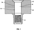
- the collar 10 is a lockbolt collar with a controlled swaging feature and used in a fastener assembly 16 having a threaded pin 18 as illustrated in FIG. 1 , for fastening a plurality of workpieces 20 , 22.
- the fastener assembly 16 includes a sleeve 24 inserted into aligned holes of the workpieces 20 , 22 , and is sized and shaped to receive the pin 18 .
- the collar 10 is used in connection with aerospace applications, such as aircraft. In other embodiments, the collar 10 can be used in other applications and fields.
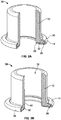
- the collar 10 includes the collar body 12 , which is relatively soft and deformable, and a galvanically compatible base element 14.
- the base element 14 is a washer which is suitable for composite structures, as shown in FIGS. 2A through 2C .
- the collar 10 includes only the soft, deformable collar body 12 , as shown in FIG. 2D , which is suitable for metallic structures.
- materials for the soft, deformable collar body 12 may include, but are not limited to, aluminum and its alloys, such as 2099, 7075, 2024 and 6061.
- FIG. 3 is a graph showing a comparison of specific tensile strength (UTS/density) of various collar materials. In particular, in an embodiment, the graph shows that the specific tensile strength of aluminum 2099 compares favorably with other materials used to make collars.
- FIG. 4 illustrates an embodiment of a plurality of the collars 10 installed on a carbon fiber reinforced plastic (CFRP) workpiece.
- CFRP carbon fiber reinforced plastic
- the collar 10 may have a nano-grain structure achieved by cold working the collar 10 via in-situ forming process during fastener installation and creating a functional gradient material (FGM), as shown in FIG. 5 .
- FGM functional gradient material
- this gradient in microstructure results in gradient in properties across the collar's 10 cross section and provides the necessary functional properties, namely, high tensile and shear strength approximately equal to those of titanium collars and higher corrosion resistance.
- the degree of the cold working of the collar 10 is also controlled by varying an outside diameter of the collar 10 to provide a specified amount of deformed structure.
- the specified collar outside diameter dimension for the collar's 10 size maintains the critical deformation needed for improved performance, but keeps it below levels that may lead to unintended cracking of the collar 10 during installation.
- the FGM in other types of fasteners such as frangible collars, can be created by other means of cold working, such thread tapping or thread rolling operations.
- the collar 10 includes a coating comprising a combination of organic materials and non-conductive fillers.
- the organic material of the coating can include the family of polymers, such as epoxies, and the non-conductive fillers can include aluminum pigmented or chromated paints and the family of sol-gel coatings.
- the coating can be applied to every portion of the collar 10 , specifically to the collar body 12 .
- the coating can be applied on the collar body 12 selectively, depending on desired joint performance.
- the outer surface of the collar body 12 can include a coating comprised of a first material
- the inner surface of the collar body 12 can include a coating comprised of second material different from the first material.
- the collar 10 is electrically isolated from more noble structures, such as composite, by use of the close fitting base element 14 , such as a captive washer inserted under and covering a bearing surface 26 of the collar body 12 .
- the base element 14 can be selected from a group of metallic materials which are known to be galvanically compatible to a composite structure. In an embodiment, these materials include steel, titanium, and their alloys. In other embodiments, other alloys and non-metallic materials may be used.
- the base element 14 not only provides protection from galvanic corrosion between the collar 10 and the CFRP structure, but plays an important role as one of the critical structural elements of the fastener system 16 .
- the base element 14 includes a flat base 28 that covers the bearing surface 26 of the collar body 12 and a securing portion 30 that is crimped and secured to a flange 32 of the collar body 12 .
- the securing portion 30 is angled obliquely relative to the base 28 .
- the base element 14 includes a ridge base 34 similar in structure to the base element 14 shown in FIG .
- the base element 14 includes a swivel base element 42 , whereby a gap 44 or clearance is formed between the flange 32 of the collar body 12 and the securing portion 30 , thereby allowing the swivel base element 42 to rotate relative to the collar body 12 , and vice-versa.
- the aforedescribed base elements 14 are rigid, and, therefore, they can accommodate any possible hole misalignment during fastener installation, thereby creating a self-aligning fastener.
- the base element 14 fills any gaps between the holes and the pin 18 and assists in aligning the pin 18 .
- the base element 14 mitigates composite bearing deformation when the collar 10 is used in a composite structure.
- the base element 14 enables the collar body 12 to form during installation without direct contact with the structure. As a result, this prevents deformation (i.e., surface friction) of the collar 10 from translating into the structure.
- the collar 10 is galvanically compatible for both metallic and composite structure applications, is lighter in weight, and is less expensive as compared to titanium fasteners, and have comparable strength to titanium fasteners, as shown in the graph of FIG. 6 .
- the collar 10 is about 30% to 50% lighter than comparable titanium collars, due to the lower density of the materials used for the collar body 12.
- the collar 10 is about 40% lighter than comparable titanium collars.
- the collar 10 can be a threaded member.
- the collar 10 may be a lightly threaded collar having internal threads for aligning it on the threaded portion of the pin 18 and, thereafter, the collar 10 can be swaged onto the pin 18.
- the collar 18 may include a single thread for the aforesaid alignment purposes, as disclosed in U.S. Patent No.
- the collar body 12 of the collar 10 may be a two-piece element, such that the elongated, tubular member of the collar body 12 is made from a soft, deformable material, such as aluminum and its alloys as described above, and the flange is made from a galvanically compatible material, such as titanium, steel, and their alloys as described above, and in which the tubular member and the flange are attached to one another.
- the tubular member and the flange are attached to one another by friction welding, adhesives, or other suitable attachment means known in the art.
Description
- The present invention relates to a collar for a fastening system and, more particularly, a hybrid collar for protection from galvanic corrosion between the collar and a structure.
- The use of composite materials, such as carbon fiber reinforced plastics (CFRP), is becoming more common in the aerospace industry as advancements on composite technologies increase. A significant portion of a composite structure is fabricated as near net-shape, but it is drilled in order to facilitate the joining of components by using mechanical fasteners. One of the most essential criteria for choosing fasteners for aircraft structures is the galvanic corrosion compatibility between the fasteners and the joined components.
-
US 2004/0234358 A1 relates to a fastener assembly comprising a metal nut having an integral flange and a metal cup washer rotatably mounted on the flange, with an outer disc surface of the flange adjacent to an inner disc surface of the washer, and with portions of a side wall of the washer overlying the flange to hold the washer captive on the flange. An outer disc surface of the washer, which engages a surface of a workpiece, has a plurality of grooves extending transversely to the circumference of the outer disc surface. The entire fastener assembly is coated, as a unit, with an anti-corrosive lubricant. -
GB 1 331 460 -
US 4,348,140 A relates to a connecting device for joining sheet metal components. The connecting device has a layer of synthetic material at least in the area of the contact surfaces with neighboring components thus effectively preventing contact corrosion. - The invention relates to a collar for a fastening system according to the features of claim 1. In an embodiment, the first material is selected from the group consisting of aluminum and aluminum alloys. In an embodiment, the second material is selected from the group consisting of steel, steel alloys, titanium, and titanium alloys.
- In an embodiment, the securing portion of the base element is crimped on the flange of the collar body. In an embodiment, the collar body includes an aperture extending from the first end to the second thereof and forming an inner wall, and wherein the base element includes a sealing portion that extends into the aperture of the collar body and covers a portion of the inner wall. In an embodiment, the base element includes a swivel base element that is adapted to rotate relative to the collar body. In an embodiment, the collar is adapted to be installed on a structure made of a composite material.
- In an embodiment, the collar has a coating that includes an organic material and a non-conductive filler. In an embodiment, the organic material is a polymer material, and the non-conductive filler is selected from the group consisting of aluminum pigmented paint, chromated paint, and sol-gel coatings. In an embodiment, the coating is applied to every portion of the collar body. In an embodiment, the coating is be applied on the collar body selectively.
- In an embodiment, the collar is a threaded collar. In another embodiment, the collar is a swage collar.
- In an embodiment, a collar body having a first end and a second end opposite the first end, the collar body being made from a first material; and a flange located at the second end of the collar body, the flange being made from a second material that is galvanically compatible with the first material. In an embodiment, the collar body and the flange are formed integrally with one another. In an embodiment, the first material is selected from the group consisting of aluminum and aluminum alloys. In an embodiment, the second material is selected from the group consisting of steel, steel alloys, titanium, and titanium alloys.
- For a more complete understanding of the present invention, reference is made to the following detailed description of exemplary embodiments considered in conjunction with the accompanying drawings, in which:
-
FIG. 1 is a cross-sectional view of an embodiment of a lockbolt fastener system; -
FIG. 2A is a partially sectioned perspective view of an embodiment of a hybrid collar adapted for use in the fastener system shown inFIG. 1 , the collar including a flat base element; -
FIG. 2B is a partially sectioned perspective view of another embodiment of a hybrid collar including a ridge base element; -
FIG. 2C is a partially sectioned perspective view of another embodiment of a hybrid collar including a swivel base element; -
FIG. 2D is a partially sectioned perspective view of another embodiment of a hybrid collar including an integrally formed flange; -
FIG. 3 is a graph showing a comparison of specific tensile strength (UTS/density) of various collar materials; -
FIG. 4 is a perspective view of an embodiment of a plurality of hybrid collars installed on a carbon fiber reinforced plastic (CFRP) structure; -
FIG. 5 is a micrograph showing a functional gradient microstructure of hybrid collar achieved by in-situ cold working during fastener installation; -
FIG. 6 is a graph illustrating the tensile strength of an aluminum hybrid collar versus a titanium collar showing equivalent ultimate strength; and -
FIG. 7 are perspective views of an embodiment of hybrid collars tested with composite plate after salt spray corrosion testing. - In an embodiment, a
hybrid collar 10 is adapted to prevent galvanic corrosion and reduce weight as compared to a conventional titanium lockbolt collar. Thecollar 10 combines acollar body 12 with a galvanicallycompatible base element 14. In an embodiment, thecollar 10 is a lockbolt collar with a controlled swaging feature and used in afastener assembly 16 having a threadedpin 18 as illustrated inFIG. 1 , for fastening a plurality ofworkpieces fastener assembly 16 includes asleeve 24 inserted into aligned holes of theworkpieces pin 18. In an embodiment, thecollar 10 is used in connection with aerospace applications, such as aircraft. In other embodiments, thecollar 10 can be used in other applications and fields. - Referring to
FIGS. 2A through 2C , thecollar 10 includes thecollar body 12, which is relatively soft and deformable, and a galvanicallycompatible base element 14. In an embodiment, thebase element 14 is a washer which is suitable for composite structures, as shown inFIGS. 2A through 2C . In another embodiment, thecollar 10 includes only the soft,deformable collar body 12, as shown inFIG. 2D , which is suitable for metallic structures. - In a number of embodiments, materials for the soft,
deformable collar body 12 may include, but are not limited to, aluminum and its alloys, such as 2099, 7075, 2024 and 6061.FIG. 3 is a graph showing a comparison of specific tensile strength (UTS/density) of various collar materials. In particular, in an embodiment, the graph shows that the specific tensile strength ofaluminum 2099 compares favorably with other materials used to make collars. -
FIG. 4 illustrates an embodiment of a plurality of thecollars 10 installed on a carbon fiber reinforced plastic (CFRP) workpiece. - In an embodiment, the
collar 10 may have a nano-grain structure achieved by cold working thecollar 10 via in-situ forming process during fastener installation and creating a functional gradient material (FGM), as shown inFIG. 5 . In an embodiment, this gradient in microstructure results in gradient in properties across the collar's 10 cross section and provides the necessary functional properties, namely, high tensile and shear strength approximately equal to those of titanium collars and higher corrosion resistance. In an embodiment, the degree of the cold working of thecollar 10 is also controlled by varying an outside diameter of thecollar 10 to provide a specified amount of deformed structure. In an embodiment, the specified collar outside diameter dimension for the collar's 10 size maintains the critical deformation needed for improved performance, but keeps it below levels that may lead to unintended cracking of thecollar 10 during installation. In other embodiments, the FGM in other types of fasteners such as frangible collars, can be created by other means of cold working, such thread tapping or thread rolling operations. - In other embodiments, the
collar 10 includes a coating comprising a combination of organic materials and non-conductive fillers. In an embodiment, the organic material of the coating can include the family of polymers, such as epoxies, and the non-conductive fillers can include aluminum pigmented or chromated paints and the family of sol-gel coatings. In one embodiment, the coating can be applied to every portion of thecollar 10, specifically to thecollar body 12. In other embodiments, the coating can be applied on thecollar body 12 selectively, depending on desired joint performance. In another embodiment, the outer surface of thecollar body 12 can include a coating comprised of a first material, and the inner surface of thecollar body 12 can include a coating comprised of second material different from the first material. - In an embodiment, the
collar 10 is electrically isolated from more noble structures, such as composite, by use of the closefitting base element 14, such as a captive washer inserted under and covering a bearingsurface 26 of thecollar body 12. In an embodiment, thebase element 14 can be selected from a group of metallic materials which are known to be galvanically compatible to a composite structure. In an embodiment, these materials include steel, titanium, and their alloys. In other embodiments, other alloys and non-metallic materials may be used. - in an embodiment, the
base element 14 not only provides protection from galvanic corrosion between thecollar 10 and the CFRP structure, but plays an important role as one of the critical structural elements of thefastener system 16. In an embodiment, as shown inFIG. 2A , thebase element 14 includes aflat base 28 that covers the bearingsurface 26 of thecollar body 12 and a securingportion 30 that is crimped and secured to aflange 32 of thecollar body 12. In an embodiment, the securingportion 30 is angled obliquely relative to thebase 28. In another embodiment, as shown inFIG. 2B , thebase element 14 includes aridge base 34 similar in structure to thebase element 14 shown inFIG. 2A , but includes a sealingportion 36 that extends into theaperture 38 of thecollar body 12 and partially covers aninner wall 40 thereof. In an embodiment, the sealingportion 36 acts as a seal for preventing moisture and other external elements from infiltrating theaperture 38 of thecollar body 12. In another embodiment, as shown inFIG. 2C , thebase element 14 includes aswivel base element 42, whereby agap 44 or clearance is formed between theflange 32 of thecollar body 12 and the securingportion 30, thereby allowing theswivel base element 42 to rotate relative to thecollar body 12, and vice-versa. In an embodiment, theaforedescribed base elements 14 are rigid, and, therefore, they can accommodate any possible hole misalignment during fastener installation, thereby creating a self-aligning fastener. In an embodiment, in instances where the hole(s) of theworkpieces base element 14 fills any gaps between the holes and thepin 18 and assists in aligning thepin 18. - In an embodiment, the
base element 14 mitigates composite bearing deformation when thecollar 10 is used in a composite structure. In an embodiment, thebase element 14 enables thecollar body 12 to form during installation without direct contact with the structure. As a result, this prevents deformation (i.e., surface friction) of thecollar 10 from translating into the structure.
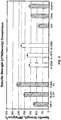
In an embodiment, thecollar 10 is galvanically compatible for both metallic and composite structure applications, is lighter in weight, and is less expensive as compared to titanium fasteners, and have comparable strength to titanium fasteners, as shown in the graph ofFIG. 6 . In an embodiment, thecollar 10 is about 30% to 50% lighter than comparable titanium collars, due to the lower density of the materials used for thecollar body 12. In another embodiment, thecollar 10 is about 40% lighter than comparable titanium collars.
FIG. 7 illustrates an embodiment of a plurality of thecollars 10 tested with a composite plate after salt spray corrosion testing. In an embodiment, thecollars 10 show no evidence of any galvanic corrosion after a 250 hour salt spray exposure.
It will be understood that the embodiments described herein are merely exemplary and that a person skilled in the art may make many variations and modifications. For instance, in an embodiment, thecollar 10 can be a threaded member. In an embodiment, thecollar 10 may be a lightly threaded collar having internal threads for aligning it on the threaded portion of thepin 18 and, thereafter, thecollar 10 can be swaged onto thepin 18. In other embodiments, thecollar 18 may include a single thread for the aforesaid alignment purposes, as disclosed inU.S. Patent No. 4,867,625 to Dixon .
In another embodiment, thecollar body 12 of thecollar 10 may be a two-piece element, such that the elongated, tubular member of thecollar body 12 is made from a soft, deformable material, such as aluminum and its alloys as described above, and the flange is made from a galvanically compatible material, such as titanium, steel, and their alloys as described above, and in which the tubular member and the flange are attached to one another. In one or more embodiments, the tubular member and the flange are attached to one another by friction welding, adhesives, or other suitable attachment means known in the art.
Claims (14)
- A collar (10), comprising a collar body (12) having a first end, a second end opposite the first end, and a flange (32) located at the second end and having a bearing surface (26), wherein the collar (10) further comprises a base element (14) attached to the collar body (12), the base element (14) including a base portion (28) that covers the bearing surface (26) of the collar body (12), and a securing portion (30) that is joined to the flange (32) of the collar body (12), characterized in that the collar body (12) is made from a first material and the base element (14) is made from a second material that is galvanically compatible with the first material; or
in that the collar body (12) is made from a first material and the flange (32) is made from a second material that is galvanically compatible with the first material. - The collar (10) of claim 1, wherein the first material is selected from the group consisting of aluminum and aluminum alloys.
- The collar (10) of claim 1 or 2, wherein the second material is selected from the group consisting of steel, steel alloys, titanium, and titanium alloys.
- The collar (10) of one of the claims 1 to 3, wherein the securing portion (30) of the base element (14) is crimped on the flange (32) of the collar body (12).
- The collar (10) of one of the claims 1 to 4, wherein the collar body (12) includes an aperture (38) extending from the first end to the second end thereof and forming an inner wall (40), and wherein the base element (14) includes a sealing portion (36) that extends into the aperture (38) of the collar body (12) and covers a portion of the inner wall (40).
- The collar (10) of one of the claims 1 to 5, wherein the base element (14) includes a swivel base element (42) that is adapted to rotate relative to the collar body (12).
- The collar (10) of one of the claims 1 to 6, wherein the collar (10) is adapted to be installed on a structure made of a composite material.
- The collar (10) of one of the claims 1 to 7, further comprising a coating that includes an organic material and a non-conductive filler.
- The collar (10) of claim 8, wherein the organic material is a polymer material, and the non-conductive filler is selected from the group consisting of aluminum pigmented paint, chromated paint, and sol-gel coatings.
- The collar (10) of claim 8 or 9, wherein the coating is applied to every portion of the collar body (12).
- The collar (10) of claim 8 or 9, wherein the coating is be applied on the collar body (12) selectively.
- The collar (10) of one of the claims 1 to 11, wherein the collar (10) is a threaded collar.
- The collar (10) of one of the claims 1 to 11, wherein the collar (10) is a swage collar.
- The collar (10) of one of the claims 1 to 13, wherein the collar body (12) and the flange (32) are formed integrally with one another.
Applications Claiming Priority (2)
| Application Number | Priority Date | Filing Date | Title |
|---|---|---|---|
| US201161467002P | 2011-03-24 | 2011-03-24 | |
| PCT/US2012/030099 WO2012129390A1 (en) | 2011-03-24 | 2012-03-22 | Hybrid collar for fastening systems |
Publications (2)
| Publication Number | Publication Date |
|---|---|
| EP2689149A1 EP2689149A1 (en) | 2014-01-29 |
| EP2689149B1 true EP2689149B1 (en) | 2017-05-03 |
Family
ID=45937620
Family Applications (1)
| Application Number | Title | Priority Date | Filing Date |
|---|---|---|---|
| EP12713497.1A Not-in-force EP2689149B1 (en) | 2011-03-24 | 2012-03-22 | Hybrid collar for fastening systems |
Country Status (5)
| Country | Link |
|---|---|
| US (1) | US20130078054A1 (en) |
| EP (1) | EP2689149B1 (en) |
| CN (2) | CN202883609U (en) |
| ES (1) | ES2634422T3 (en) |
| WO (1) | WO2012129390A1 (en) |
Families Citing this family (3)
| Publication number | Priority date | Publication date | Assignee | Title |
|---|---|---|---|---|
| ES2634422T3 (en) * | 2011-03-24 | 2017-09-27 | Alcoa Inc. | Hybrid collar for fastening systems |
| ES2710362T3 (en) | 2013-09-19 | 2019-04-24 | Arconic Inc | Rivet |
| WO2015041721A1 (en) * | 2013-09-19 | 2015-03-26 | Alcoa Inc. | Lock bolt collar with high standoff internal bead |
Family Cites Families (20)
| Publication number | Priority date | Publication date | Assignee | Title |
|---|---|---|---|---|
| FR2071515A5 (en) * | 1969-12-31 | 1971-09-17 | Simmonds | |
| US3911783A (en) * | 1973-02-05 | 1975-10-14 | Townsend Company A Division Of | Rivet of titanium-columbium alloy and method of making the same |
| GB2006907B (en) * | 1977-10-28 | 1982-05-26 | Messerschmitt Boelkow Blohm | Connection device proncipally for sheet metal components of light metal alloys |
| US4784549A (en) * | 1985-02-15 | 1988-11-15 | Wing George S | Torque-limited collar |
| US4867625A (en) | 1985-04-29 | 1989-09-19 | Huck Manufacturing Company | Variable clamp fastener and method |
| US4760493A (en) * | 1985-09-30 | 1988-07-26 | The Boeing Company | Lightning protection system for composite material aircraft structures |
| US4986712A (en) * | 1989-12-18 | 1991-01-22 | Emhart Industries, Inc. | Fastener assembly |
| US5393182A (en) * | 1993-10-25 | 1995-02-28 | Microdot Inc. | Seal nut |
| US5688091A (en) * | 1995-09-15 | 1997-11-18 | Hong-Kong Disc Lock Company, Ltd. | Self-locking fastener with captive washer |
| SE512678C2 (en) * | 1995-12-09 | 2000-05-02 | Neumayer Erich Gmbh Co Kg | Process for producing a composition nut as well as a nut prepared by the method |
| US5692863A (en) * | 1996-01-25 | 1997-12-02 | Fairchild Fasteners-U.S. | Self-locking preload controlling nut |
| DE19725329C2 (en) * | 1997-06-16 | 2001-12-13 | Zahnradfabrik Friedrichshafen | Screw with a screw head |
| US6132153A (en) * | 1999-09-02 | 2000-10-17 | Illinois Tool Works Inc. | Zero on prevailing torque nut |
| EP1295046B2 (en) * | 2000-06-23 | 2015-08-26 | Hi-Shear Corporation | Swage collar with internal sealing insert |
| US20040234358A1 (en) * | 2003-05-21 | 2004-11-25 | Newfrey Llc | Fastener assembly and method employing a flanged metal nut with a metal cup washer rotatably mounted thereon |
| GB0525689D0 (en) * | 2005-12-16 | 2006-01-25 | Airbus Uk Ltd | A fastener assembly |
| US7695226B2 (en) * | 2006-09-21 | 2010-04-13 | Alcoa Global Fasteners, Inc. | High performance sleeved interference fasteners for composite applications |
| DE102007003276B4 (en) * | 2007-01-23 | 2013-11-28 | Airbus Operations Gmbh | Aerospace vehicle with a CFRP component and a metal component, wherein the CFRP component and the metal component are connected to each other via at least one connecting element with a connecting portion |
| FR2929665A1 (en) * | 2008-04-04 | 2009-10-09 | Eris Sarl | METHOD FOR ASSEMBLING COMPOSITE MATERIALS AND RIBBING DEVICE FOR IMPLEMENTING THE SAME |
| ES2634422T3 (en) * | 2011-03-24 | 2017-09-27 | Alcoa Inc. | Hybrid collar for fastening systems |
-
2012
- 2012-03-22 ES ES12713497.1T patent/ES2634422T3/en active Active
- 2012-03-22 US US13/427,080 patent/US20130078054A1/en not_active Abandoned
- 2012-03-22 WO PCT/US2012/030099 patent/WO2012129390A1/en active Application Filing
- 2012-03-22 EP EP12713497.1A patent/EP2689149B1/en not_active Not-in-force
- 2012-03-23 CN CN201220280890.2U patent/CN202883609U/en not_active Expired - Fee Related
- 2012-03-23 CN CN2012101955415A patent/CN102734292A/en active Pending
Also Published As
| Publication number | Publication date |
|---|---|
| CN102734292A (en) | 2012-10-17 |
| EP2689149A1 (en) | 2014-01-29 |
| ES2634422T3 (en) | 2017-09-27 |
| US20130078054A1 (en) | 2013-03-28 |
| CN202883609U (en) | 2013-04-17 |
| WO2012129390A1 (en) | 2012-09-27 |
Similar Documents
| Publication | Publication Date | Title |
|---|---|---|
| EP3584289B1 (en) | Blind fastener system with electromagnetic effects-protective coating | |
| US10294976B2 (en) | Method of installing a structural blind fastener | |
| US10014593B2 (en) | Conductive sleeved fastener assembly | |
| EP2812248B1 (en) | Connecting arrangement and method for providing such connecting arrangement | |
| CN108457960B (en) | Assembly comprising a fastener and method for fastening a structure having a hole | |
| EP2947015B1 (en) | Modified shank fasteners for electromagnetic effect (eme) technology | |
| US8382413B2 (en) | Conductive sleeved fastener assembly | |
| EP2951095B1 (en) | Sleeved fastener assembly | |
| US8262331B2 (en) | Integrated expanding sleeve hole filling threaded fastener | |
| EP2689149B1 (en) | Hybrid collar for fastening systems | |
| DE102015101258A1 (en) | Method for producing a mounting unit and fastener unit for carrying out the method | |
| US20200217349A1 (en) | Conductive fastening system and method for improved eme performance | |
| US20210246929A1 (en) | Fastening assembly | |
| EP3848593A1 (en) | Conductively coated fastening systems for full size determinant assembly (fsda) | |
| US8579567B2 (en) | Device for blind fixation | |
| EP3911778B1 (en) | Expansion anchor with double coating including a zinc flake and/or aluminium flake layer | |
| US20220325742A1 (en) | Coated fastener body | |
| US20230059724A1 (en) | Galvanic corrosion resistant fastener | |
| CN117108611A (en) | Rivet connection pair, riveting device and riveting method |
Legal Events
| Date | Code | Title | Description |
|---|---|---|---|
| PUAI | Public reference made under article 153(3) epc to a published international application that has entered the european phase |
Free format text: ORIGINAL CODE: 0009012 |
|
| 17P | Request for examination filed |
Effective date: 20131014 |
|
| AK | Designated contracting states |
Kind code of ref document: A1 Designated state(s): AL AT BE BG CH CY CZ DE DK EE ES FI FR GB GR HR HU IE IS IT LI LT LU LV MC MK MT NL NO PL PT RO RS SE SI SK SM TR |
|
| DAX | Request for extension of the european patent (deleted) | ||
| 17Q | First examination report despatched |
Effective date: 20160315 |
|
| GRAP | Despatch of communication of intention to grant a patent |
Free format text: ORIGINAL CODE: EPIDOSNIGR1 |
|
| INTG | Intention to grant announced |
Effective date: 20161024 |
|
| RIN1 | Information on inventor provided before grant (corrected) |
Inventor name: HAYLOCK, LUKE Inventor name: MULAZIMOGLU, HASIM Inventor name: PINHEIRO, RODRIGO |
|
| GRAS | Grant fee paid |
Free format text: ORIGINAL CODE: EPIDOSNIGR3 |
|
| GRAA | (expected) grant |
Free format text: ORIGINAL CODE: 0009210 |
|
| RAP1 | Party data changed (applicant data changed or rights of an application transferred) |
Owner name: ARCONIC INC. |
|
| AK | Designated contracting states |
Kind code of ref document: B1 Designated state(s): AL AT BE BG CH CY CZ DE DK EE ES FI FR GB GR HR HU IE IS IT LI LT LU LV MC MK MT NL NO PL PT RO RS SE SI SK SM TR |
|
| REG | Reference to a national code |
Ref country code: GB Ref legal event code: FG4D |
|
| REG | Reference to a national code |
Ref country code: AT Ref legal event code: REF Ref document number: 890322 Country of ref document: AT Kind code of ref document: T Effective date: 20170515 Ref country code: CH Ref legal event code: EP |
|
| REG | Reference to a national code |
Ref country code: IE Ref legal event code: FG4D |
|
| REG | Reference to a national code |
Ref country code: DE Ref legal event code: R096 Ref document number: 602012031901 Country of ref document: DE |
|
| REG | Reference to a national code |
Ref country code: NL Ref legal event code: MP Effective date: 20170503 |
|
| REG | Reference to a national code |
Ref country code: AT Ref legal event code: MK05 Ref document number: 890322 Country of ref document: AT Kind code of ref document: T Effective date: 20170503 |
|
| REG | Reference to a national code |
Ref country code: LT Ref legal event code: MG4D |
|
| REG | Reference to a national code |
Ref country code: ES Ref legal event code: FG2A Ref document number: 2634422 Country of ref document: ES Kind code of ref document: T3 Effective date: 20170927 |
|
| PG25 | Lapsed in a contracting state [announced via postgrant information from national office to epo] |
Ref country code: HR Free format text: LAPSE BECAUSE OF FAILURE TO SUBMIT A TRANSLATION OF THE DESCRIPTION OR TO PAY THE FEE WITHIN THE PRESCRIBED TIME-LIMIT Effective date: 20170503 Ref country code: GR Free format text: LAPSE BECAUSE OF FAILURE TO SUBMIT A TRANSLATION OF THE DESCRIPTION OR TO PAY THE FEE WITHIN THE PRESCRIBED TIME-LIMIT Effective date: 20170804 Ref country code: AT Free format text: LAPSE BECAUSE OF FAILURE TO SUBMIT A TRANSLATION OF THE DESCRIPTION OR TO PAY THE FEE WITHIN THE PRESCRIBED TIME-LIMIT Effective date: 20170503 Ref country code: NO Free format text: LAPSE BECAUSE OF FAILURE TO SUBMIT A TRANSLATION OF THE DESCRIPTION OR TO PAY THE FEE WITHIN THE PRESCRIBED TIME-LIMIT Effective date: 20170803 Ref country code: LT Free format text: LAPSE BECAUSE OF FAILURE TO SUBMIT A TRANSLATION OF THE DESCRIPTION OR TO PAY THE FEE WITHIN THE PRESCRIBED TIME-LIMIT Effective date: 20170503 Ref country code: FI Free format text: LAPSE BECAUSE OF FAILURE TO SUBMIT A TRANSLATION OF THE DESCRIPTION OR TO PAY THE FEE WITHIN THE PRESCRIBED TIME-LIMIT Effective date: 20170503 |
|
| PG25 | Lapsed in a contracting state [announced via postgrant information from national office to epo] |
Ref country code: PL Free format text: LAPSE BECAUSE OF FAILURE TO SUBMIT A TRANSLATION OF THE DESCRIPTION OR TO PAY THE FEE WITHIN THE PRESCRIBED TIME-LIMIT Effective date: 20170503 Ref country code: IS Free format text: LAPSE BECAUSE OF FAILURE TO SUBMIT A TRANSLATION OF THE DESCRIPTION OR TO PAY THE FEE WITHIN THE PRESCRIBED TIME-LIMIT Effective date: 20170903 Ref country code: NL Free format text: LAPSE BECAUSE OF FAILURE TO SUBMIT A TRANSLATION OF THE DESCRIPTION OR TO PAY THE FEE WITHIN THE PRESCRIBED TIME-LIMIT Effective date: 20170503 Ref country code: BG Free format text: LAPSE BECAUSE OF FAILURE TO SUBMIT A TRANSLATION OF THE DESCRIPTION OR TO PAY THE FEE WITHIN THE PRESCRIBED TIME-LIMIT Effective date: 20170803 Ref country code: LV Free format text: LAPSE BECAUSE OF FAILURE TO SUBMIT A TRANSLATION OF THE DESCRIPTION OR TO PAY THE FEE WITHIN THE PRESCRIBED TIME-LIMIT Effective date: 20170503 Ref country code: RS Free format text: LAPSE BECAUSE OF FAILURE TO SUBMIT A TRANSLATION OF THE DESCRIPTION OR TO PAY THE FEE WITHIN THE PRESCRIBED TIME-LIMIT Effective date: 20170503 Ref country code: SE Free format text: LAPSE BECAUSE OF FAILURE TO SUBMIT A TRANSLATION OF THE DESCRIPTION OR TO PAY THE FEE WITHIN THE PRESCRIBED TIME-LIMIT Effective date: 20170503 |
|
| PG25 | Lapsed in a contracting state [announced via postgrant information from national office to epo] |
Ref country code: CZ Free format text: LAPSE BECAUSE OF FAILURE TO SUBMIT A TRANSLATION OF THE DESCRIPTION OR TO PAY THE FEE WITHIN THE PRESCRIBED TIME-LIMIT Effective date: 20170503 Ref country code: RO Free format text: LAPSE BECAUSE OF FAILURE TO SUBMIT A TRANSLATION OF THE DESCRIPTION OR TO PAY THE FEE WITHIN THE PRESCRIBED TIME-LIMIT Effective date: 20170503 Ref country code: DK Free format text: LAPSE BECAUSE OF FAILURE TO SUBMIT A TRANSLATION OF THE DESCRIPTION OR TO PAY THE FEE WITHIN THE PRESCRIBED TIME-LIMIT Effective date: 20170503 Ref country code: EE Free format text: LAPSE BECAUSE OF FAILURE TO SUBMIT A TRANSLATION OF THE DESCRIPTION OR TO PAY THE FEE WITHIN THE PRESCRIBED TIME-LIMIT Effective date: 20170503 Ref country code: SK Free format text: LAPSE BECAUSE OF FAILURE TO SUBMIT A TRANSLATION OF THE DESCRIPTION OR TO PAY THE FEE WITHIN THE PRESCRIBED TIME-LIMIT Effective date: 20170503 |
|
| REG | Reference to a national code |
Ref country code: DE Ref legal event code: R097 Ref document number: 602012031901 Country of ref document: DE |
|
| PG25 | Lapsed in a contracting state [announced via postgrant information from national office to epo] |
Ref country code: IT Free format text: LAPSE BECAUSE OF FAILURE TO SUBMIT A TRANSLATION OF THE DESCRIPTION OR TO PAY THE FEE WITHIN THE PRESCRIBED TIME-LIMIT Effective date: 20170503 Ref country code: SM Free format text: LAPSE BECAUSE OF FAILURE TO SUBMIT A TRANSLATION OF THE DESCRIPTION OR TO PAY THE FEE WITHIN THE PRESCRIBED TIME-LIMIT Effective date: 20170503 |
|
| PLBE | No opposition filed within time limit |
Free format text: ORIGINAL CODE: 0009261 |
|
| STAA | Information on the status of an ep patent application or granted ep patent |
Free format text: STATUS: NO OPPOSITION FILED WITHIN TIME LIMIT |
|
| REG | Reference to a national code |
Ref country code: FR Ref legal event code: PLFP Year of fee payment: 7 |
|
| 26N | No opposition filed |
Effective date: 20180206 |
|
| PG25 | Lapsed in a contracting state [announced via postgrant information from national office to epo] |
Ref country code: SI Free format text: LAPSE BECAUSE OF FAILURE TO SUBMIT A TRANSLATION OF THE DESCRIPTION OR TO PAY THE FEE WITHIN THE PRESCRIBED TIME-LIMIT Effective date: 20170503 |
|
| REG | Reference to a national code |
Ref country code: CH Ref legal event code: PL |
|
| PG25 | Lapsed in a contracting state [announced via postgrant information from national office to epo] |
Ref country code: MC Free format text: LAPSE BECAUSE OF FAILURE TO SUBMIT A TRANSLATION OF THE DESCRIPTION OR TO PAY THE FEE WITHIN THE PRESCRIBED TIME-LIMIT Effective date: 20170503 |
|
| REG | Reference to a national code |
Ref country code: BE Ref legal event code: MM Effective date: 20180331 |
|
| REG | Reference to a national code |
Ref country code: IE Ref legal event code: MM4A |
|
| PG25 | Lapsed in a contracting state [announced via postgrant information from national office to epo] |
Ref country code: LU Free format text: LAPSE BECAUSE OF NON-PAYMENT OF DUE FEES Effective date: 20180322 |
|
| PG25 | Lapsed in a contracting state [announced via postgrant information from national office to epo] |
Ref country code: IE Free format text: LAPSE BECAUSE OF NON-PAYMENT OF DUE FEES Effective date: 20180322 |
|
| PG25 | Lapsed in a contracting state [announced via postgrant information from national office to epo] |
Ref country code: BE Free format text: LAPSE BECAUSE OF NON-PAYMENT OF DUE FEES Effective date: 20180331 Ref country code: LI Free format text: LAPSE BECAUSE OF NON-PAYMENT OF DUE FEES Effective date: 20180331 Ref country code: CH Free format text: LAPSE BECAUSE OF NON-PAYMENT OF DUE FEES Effective date: 20180331 |
|
| PGFP | Annual fee paid to national office [announced via postgrant information from national office to epo] |
Ref country code: DE Payment date: 20190219 Year of fee payment: 8 Ref country code: GB Payment date: 20190222 Year of fee payment: 8 |
|
| PGFP | Annual fee paid to national office [announced via postgrant information from national office to epo] |
Ref country code: FR Payment date: 20190220 Year of fee payment: 8 |
|
| REG | Reference to a national code |
Ref country code: DE Ref legal event code: R082 Ref document number: 602012031901 Country of ref document: DE Representative=s name: MEISSNER BOLTE PATENTANWAELTE RECHTSANWAELTE P, DE |
|
| PGFP | Annual fee paid to national office [announced via postgrant information from national office to epo] |
Ref country code: ES Payment date: 20190401 Year of fee payment: 8 |
|
| REG | Reference to a national code |
Ref country code: ES Ref legal event code: PC2A Owner name: ARCONIC INC. Effective date: 20190920 |
|
| PG25 | Lapsed in a contracting state [announced via postgrant information from national office to epo] |
Ref country code: MT Free format text: LAPSE BECAUSE OF NON-PAYMENT OF DUE FEES Effective date: 20180322 |
|
| PG25 | Lapsed in a contracting state [announced via postgrant information from national office to epo] |
Ref country code: TR Free format text: LAPSE BECAUSE OF FAILURE TO SUBMIT A TRANSLATION OF THE DESCRIPTION OR TO PAY THE FEE WITHIN THE PRESCRIBED TIME-LIMIT Effective date: 20170503 |
|
| PG25 | Lapsed in a contracting state [announced via postgrant information from national office to epo] |
Ref country code: PT Free format text: LAPSE BECAUSE OF FAILURE TO SUBMIT A TRANSLATION OF THE DESCRIPTION OR TO PAY THE FEE WITHIN THE PRESCRIBED TIME-LIMIT Effective date: 20170503 Ref country code: HU Free format text: LAPSE BECAUSE OF FAILURE TO SUBMIT A TRANSLATION OF THE DESCRIPTION OR TO PAY THE FEE WITHIN THE PRESCRIBED TIME-LIMIT; INVALID AB INITIO Effective date: 20120322 |
|
| PG25 | Lapsed in a contracting state [announced via postgrant information from national office to epo] |
Ref country code: CY Free format text: LAPSE BECAUSE OF FAILURE TO SUBMIT A TRANSLATION OF THE DESCRIPTION OR TO PAY THE FEE WITHIN THE PRESCRIBED TIME-LIMIT Effective date: 20170503 Ref country code: MK Free format text: LAPSE BECAUSE OF NON-PAYMENT OF DUE FEES Effective date: 20170503 |
|
| PG25 | Lapsed in a contracting state [announced via postgrant information from national office to epo] |
Ref country code: AL Free format text: LAPSE BECAUSE OF FAILURE TO SUBMIT A TRANSLATION OF THE DESCRIPTION OR TO PAY THE FEE WITHIN THE PRESCRIBED TIME-LIMIT Effective date: 20170503 |
|
| REG | Reference to a national code |
Ref country code: DE Ref legal event code: R119 Ref document number: 602012031901 Country of ref document: DE |
|
| PG25 | Lapsed in a contracting state [announced via postgrant information from national office to epo] |
Ref country code: FR Free format text: LAPSE BECAUSE OF NON-PAYMENT OF DUE FEES Effective date: 20200331 Ref country code: DE Free format text: LAPSE BECAUSE OF NON-PAYMENT OF DUE FEES Effective date: 20201001 |
|
| GBPC | Gb: european patent ceased through non-payment of renewal fee |
Effective date: 20200322 |
|
| PG25 | Lapsed in a contracting state [announced via postgrant information from national office to epo] |
Ref country code: GB Free format text: LAPSE BECAUSE OF NON-PAYMENT OF DUE FEES Effective date: 20200322 |
|
| REG | Reference to a national code |
Ref country code: ES Ref legal event code: FD2A Effective date: 20210806 |
|
| PG25 | Lapsed in a contracting state [announced via postgrant information from national office to epo] |
Ref country code: ES Free format text: LAPSE BECAUSE OF NON-PAYMENT OF DUE FEES Effective date: 20200323 |