EP2688464B1 - Autoinjector with infrared sensor - Google Patents
Autoinjector with infrared sensor Download PDFInfo
- Publication number
- EP2688464B1 EP2688464B1 EP12717204.7A EP12717204A EP2688464B1 EP 2688464 B1 EP2688464 B1 EP 2688464B1 EP 12717204 A EP12717204 A EP 12717204A EP 2688464 B1 EP2688464 B1 EP 2688464B1
- Authority
- EP
- European Patent Office
- Prior art keywords
- sensor
- autoinjector
- source
- skin
- signal
- Prior art date
- Legal status (The legal status is an assumption and is not a legal conclusion. Google has not performed a legal analysis and makes no representation as to the accuracy of the status listed.)
- Active
Links
Images


Classifications
-
- A—HUMAN NECESSITIES
- A61—MEDICAL OR VETERINARY SCIENCE; HYGIENE
- A61M—DEVICES FOR INTRODUCING MEDIA INTO, OR ONTO, THE BODY; DEVICES FOR TRANSDUCING BODY MEDIA OR FOR TAKING MEDIA FROM THE BODY; DEVICES FOR PRODUCING OR ENDING SLEEP OR STUPOR
- A61M5/00—Devices for bringing media into the body in a subcutaneous, intra-vascular or intramuscular way; Accessories therefor, e.g. filling or cleaning devices, arm-rests
- A61M5/178—Syringes
- A61M5/31—Details
-
- A—HUMAN NECESSITIES
- A61—MEDICAL OR VETERINARY SCIENCE; HYGIENE
- A61M—DEVICES FOR INTRODUCING MEDIA INTO, OR ONTO, THE BODY; DEVICES FOR TRANSDUCING BODY MEDIA OR FOR TAKING MEDIA FROM THE BODY; DEVICES FOR PRODUCING OR ENDING SLEEP OR STUPOR
- A61M5/00—Devices for bringing media into the body in a subcutaneous, intra-vascular or intramuscular way; Accessories therefor, e.g. filling or cleaning devices, arm-rests
- A61M5/178—Syringes
- A61M5/20—Automatic syringes, e.g. with automatically actuated piston rod, with automatic needle injection, filling automatically
-
- G—PHYSICS
- G01—MEASURING; TESTING
- G01N—INVESTIGATING OR ANALYSING MATERIALS BY DETERMINING THEIR CHEMICAL OR PHYSICAL PROPERTIES
- G01N21/00—Investigating or analysing materials by the use of optical means, i.e. using sub-millimetre waves, infrared, visible or ultraviolet light
- G01N21/17—Systems in which incident light is modified in accordance with the properties of the material investigated
- G01N21/47—Scattering, i.e. diffuse reflection
- G01N21/4738—Diffuse reflection, e.g. also for testing fluids, fibrous materials
-
- G—PHYSICS
- G01—MEASURING; TESTING
- G01N—INVESTIGATING OR ANALYSING MATERIALS BY DETERMINING THEIR CHEMICAL OR PHYSICAL PROPERTIES
- G01N21/00—Investigating or analysing materials by the use of optical means, i.e. using sub-millimetre waves, infrared, visible or ultraviolet light
- G01N21/17—Systems in which incident light is modified in accordance with the properties of the material investigated
- G01N21/47—Scattering, i.e. diffuse reflection
- G01N21/4795—Scattering, i.e. diffuse reflection spatially resolved investigating of object in scattering medium
-
- A—HUMAN NECESSITIES
- A61—MEDICAL OR VETERINARY SCIENCE; HYGIENE
- A61M—DEVICES FOR INTRODUCING MEDIA INTO, OR ONTO, THE BODY; DEVICES FOR TRANSDUCING BODY MEDIA OR FOR TAKING MEDIA FROM THE BODY; DEVICES FOR PRODUCING OR ENDING SLEEP OR STUPOR
- A61M5/00—Devices for bringing media into the body in a subcutaneous, intra-vascular or intramuscular way; Accessories therefor, e.g. filling or cleaning devices, arm-rests
- A61M5/178—Syringes
- A61M5/20—Automatic syringes, e.g. with automatically actuated piston rod, with automatic needle injection, filling automatically
- A61M2005/2006—Having specific accessories
- A61M2005/2013—Having specific accessories triggering of discharging means by contact of injector with patient body
-
- A—HUMAN NECESSITIES
- A61—MEDICAL OR VETERINARY SCIENCE; HYGIENE
- A61M—DEVICES FOR INTRODUCING MEDIA INTO, OR ONTO, THE BODY; DEVICES FOR TRANSDUCING BODY MEDIA OR FOR TAKING MEDIA FROM THE BODY; DEVICES FOR PRODUCING OR ENDING SLEEP OR STUPOR
- A61M5/00—Devices for bringing media into the body in a subcutaneous, intra-vascular or intramuscular way; Accessories therefor, e.g. filling or cleaning devices, arm-rests
- A61M5/178—Syringes
- A61M5/20—Automatic syringes, e.g. with automatically actuated piston rod, with automatic needle injection, filling automatically
- A61M2005/206—With automatic needle insertion
-
- A—HUMAN NECESSITIES
- A61—MEDICAL OR VETERINARY SCIENCE; HYGIENE
- A61M—DEVICES FOR INTRODUCING MEDIA INTO, OR ONTO, THE BODY; DEVICES FOR TRANSDUCING BODY MEDIA OR FOR TAKING MEDIA FROM THE BODY; DEVICES FOR PRODUCING OR ENDING SLEEP OR STUPOR
- A61M5/00—Devices for bringing media into the body in a subcutaneous, intra-vascular or intramuscular way; Accessories therefor, e.g. filling or cleaning devices, arm-rests
- A61M5/42—Devices for bringing media into the body in a subcutaneous, intra-vascular or intramuscular way; Accessories therefor, e.g. filling or cleaning devices, arm-rests having means for desensitising skin, for protruding skin to facilitate piercing, or for locating point where body is to be pierced
- A61M5/427—Locating point where body is to be pierced, e.g. vein location means using ultrasonic waves, injection site templates
-
- G—PHYSICS
- G01—MEASURING; TESTING
- G01N—INVESTIGATING OR ANALYSING MATERIALS BY DETERMINING THEIR CHEMICAL OR PHYSICAL PROPERTIES
- G01N21/00—Investigating or analysing materials by the use of optical means, i.e. using sub-millimetre waves, infrared, visible or ultraviolet light
- G01N21/17—Systems in which incident light is modified in accordance with the properties of the material investigated
- G01N21/25—Colour; Spectral properties, i.e. comparison of effect of material on the light at two or more different wavelengths or wavelength bands
- G01N21/31—Investigating relative effect of material at wavelengths characteristic of specific elements or molecules, e.g. atomic absorption spectrometry
- G01N21/35—Investigating relative effect of material at wavelengths characteristic of specific elements or molecules, e.g. atomic absorption spectrometry using infrared light
Definitions
- the present invention relates to an autoinjector comprising an electronic sensor for detecting skin, particularly a reconstituting autoinjector.
- Some medicaments are administered to a patient by injecting a liquid formulation of the medicament into the patient. This is typically performed using a needle coupled to a syringe.
- the liquid formulation is not stable in the liquid form and is supplied as a dried medicament and a reconstituting liquid. Prior to injection the reconstituting liquid is added to the dried medicament to create the injectable liquid formulation.
- an autoinjector to automate at least part of the process of injecting a patient, such as a human or animal. Automation of the injection step is particularly useful where a consistent depth and / or volume of injection is desirable.
- WO2009/037432 discloses a device for determining the location and orientation of a vein under the skin of a patient. This device is not coupled to an autoinjector.
- US2012/116212 teaches an autoinjector having generic sensors, which sensors relate to the operation of the injector itself.
- IR infrared
- a highly scattering material such as a body tissue like fat or muscle, or a combination of the two
- the photons are both absorbed and scattered in multiple directions in a process that can be modelled statistically.
- the result of this scattering is that a bright path (high relative average photon density) will exist within the material, and that the light will be detected at the material surface some distance from the source.
- the profile of light intensity at the material surface as a function of distance from the source is characteristic of the scattering material.
- Providing two detectors at different distances from the source means that the difference between intensity of light at each of the detectors is indicative of the characteristic of the material and this difference can therefore be used to determine whether the material into which the light is being shone has the light scattering characteristic of a body tissue into which an injection can occur.
- an EM source illuminates the surface of the material to be tested with electromagnetic (EM) radiation, while two detectors measure the intensity of EM radiation emerging from the material in two positions at different distances from the source.
- the EM source may emit infrared radiation in the infrared spectrum between wavelengths of about 0.7 micrometres and about 300 micrometres.
- the sensor is intended to test for the presence of tissue into which an injection can be made. A positive reading from the sensor can be taken as indicator that the sensor is in close proximity to skin.
- the first sensor may be positioned at the expected bright-spot for suitable tissue and the second sensor may be positioned adjacent to it as this will provide the biggest difference in signal strengths between the first and second sensors.
- the transmission of the EM radiation through the tissue is an important characteristic living tissue is not of a consistent character and the characteristic will vary at different sites around the body. For example muscle and fat will have a different scattering characteristic.
- the EM radiation emitted from the source must be detected by the sensors after it has passed through a medium.
- the scattering characteristic of tissues varies so when the sensor is in close proximity or contact with a tissue with a scattering characteristic as determined by the processing of the two signals from the detectors that matches a scattering characteristic determined for tissue into which an injection can occur the sensor is able to generate a skin signal.
- skin in this document is intended to refer to tissue into which an injection can occur, for example fat, muscle or other body tissue and not simply human or animal skin. Since the human or animal body is typically substantially covered in skin it can usually be assumed that if the sensor detects such tissue, it is in contact with, or close proximity to, skin.
- the EM source may be substantially a point source, or a source small enough to be considered substantially equivalent to one. This could be achieved by providing a plate opaque to the emitted EM radiation through which there is a pin-hole between the EM source and the material to be tested.
- the pin hole may be less than 5mm, less than 2.5mm or less than 1.5mm.
- the pinhole may be between about 1.5mm and 1mm. For these dimensions it is intended that the dimension refers to a diameter, or maximum dimension of the aperture for apertures that are not substantially circular in shape.
- the baffle is intended to prevent a direct light path from the EM source to either of the detectors.
- the baffle may be substantially planar, curved, or a combination of the two.
- the baffle may substantially surround the EM source.
- the baffle, first EM detector and second EM detector may be arranged substantially in a straight line.
- the EM source emits IR radiation
- the sensor may include a cover of IR transmitting glass. Such a cover could protect the sensor from dirt contamination or physical damage. Such a cover should cover one or more of the emitter and detectors and more than one cover may be provided.
- the processor compares the first signal strength with a first threshold to determine if the signal is strong enough to indicate that the sensor is in contact, or at least close proximity, to an IR transmissive material that has an IR scattering characteristic that is indicative of being a material into which an injection can be made. Furthermore, the processor compares the ratio between the first and second signals with a second threshold to determine whether the material has an IR scattering characteristic that is indicative of being a material into which an injection can be made.
- the processor monitors the rate of change of the first and second signals in time and compares that rate of change with a threshold to determine whether the signals are stable as this may assist in preventing the generation of false positive skin signals.
- thresholds mentioned above will depend upon many factors, for example the EM radiation being used, the location of the skin to be detected, the risk of false positives or false negatives that can be tolerated. It should be possible to set suitable limits using basic trial and error methods.
- the IR source may be an Infra Red LED, or any other suitable source and the IR detectors may be photodiodes capable of detecting incident IR radiation intensity, or any other suitable detector capable of generating a signal indicative of the intensity of IR light reaching the detector.
- the wavelength of EM radiation used is between 900 and 1000nm.
- the distance between the IR source and the first sensor may be between 0.1cm and 0.6cm, between 0.2cm and 0.5cm or may be substantially 0.3cm.
- the difference in the distance from the EM source between the first sensor and the second sensor may be between 0.1cm and 1cm, between 0.2cm and 0.7cm or between about 0.3cm and 0.5cm.
- This distance may be the distance between the two detectors if the detectors are positioned along a substantially straight line from the source to the first detector and then the second detector.
- the scattering within the tissue is not limited to a single line, but radiates from the source so the detectors need not be arranged along a line extending through the emitter.
- the autoinjector comprises a liquid container, an injector, an injection contact portion, a processor and a sensor adjacent the injection contact portion, wherein the injector is arranged to inject liquid from the liquid container into a patient at the injection contact portion, the sensor being substantially as described above and the autoinjector being configured to use the injector to inject the liquid from the container into a subject only when a positive skin signal has been received from the sensor.
- the autoinjector may include an ambient light sensor adjacent the sensor and the autoinjector may be configured to activate the sensor only when the ambient light sensor detects ambient light levels below a threshold level.
- the autoinjector may be a reconstituting autoinjector which is capable of receiving a dry medicament product and a reconstitution liquid, automatically combining them to provide an injectable medication and subsequently automatically injecting them into a patient. There may be user steps to complete before, during or after each of the automated steps.
- Figure 1 shows a graph 1 with light intensity (I) on the vertical axis 2 and distance from a light source (x) on the horizontal axis 4.
- the graph 1 shows how the light intensity (I) varies as a function of distance (x) from the source. It can be seen from the graph 1 that the light intensity (I) initially falls with increasing distance from the source, but then rises to a maximum at the point D1 from the source before falling again.
- the distance D1 is indicative of a characteristic of the light scattering properties of a material into which the light is being shone. In this case the light is an IR light.
- Figure 2 shows a schematic of the light intensity within a material 6 when a portion 8 of a surface 10 is illuminated with IR light 12. Due to light scattering within the material 6 a 'bright path' 14 is established within the material 6 in which the average light intensity is relatively higher than elsewhere. The bright path 14 is bounded by a lower intensity path 16. The bright path 14 curves through the material from the illuminated surface portion 8 until it reaches the surface 10 again at a point a distance D1 from the illuminated portion 8.
- Figure 3 shows an electronic sensor 20 for detecting skin 22, the sensor 20 comprises processor 24, an IR source 26, in this case an Infra Red emitting LED, a baffle 28, a first IR detector 30 and a second IR detector 32, in this case photo diodes.
- the IR source 26 includes an opaque plate 40 through which there is a pinhole 42 so that the IR source projects a fine point of IR light.
- the diameter of the pinhole may be less than 2mm, may be less than 1mm or may be less than 0.5mm.
- the optical power emerging through the pin hole is approximately 14 mW.
- the sensor further includes a cover 44 of a material through which IR radiation can pass.
- the cover 44 is arranged to cover the IR source 26, baffle 28, first IR detector 30 and second IR detector 32.
- the sensor 20 is arranged such that the IR source 26 is located on a first side 34 of the baffle 28 and the first and second IR detectors 30,32 are arranged on a second, opposite, side 36 of the baffle 28 at first and second distances D1,D2 from the IR source 26 respectively.
- the baffle 28 prevents IR light from passing directly from the IR source 26 to the detectors 30,32.
- the first distance D1 is less than the second distance D2.
- D1 is chosen to approximately equal the expected distance D1 between the IR source 26 and the point at which the bright path mentioned above reaches the surface of flesh, or other suitable body tissue, covered by skin.
- the IR source 24, baffle 28, first and second detectors 30,32 are arranged substantially along a straight line.
- the processor 24 is configured to selectively cause the IR source 26 to emit IR radiation and to receive first and second signals S1,S2 from the first and second IR detectors 30,32 respectively.
- the sensor 20 further includes a power source 38 to provide power the various components.
- the power source 38 may be integral with the sensor, or external.
- the signals received are indicative of the intensity of IR radiation detected by each sensor 30,32.
- the processor is configured to process the first and second signals and thereby generate a skin signal which is indicative of whether the sensor has detected skin.
- Figure 4 shows an autoinjector 50 comprising a liquid container 52, an injector 54, an injection contact portion 56, processor 58 and a sensor 20 adjacent the injection contact portion 56.
- the injector 54 is arranged to inject liquid from the liquid container 52 into a patient at the site of the injection contact portion 56.
- the autoinjector 50 is configured to use the injector 54 to inject the liquid into a subject only when a positive skin signal has been received from the sensor 20.
- the autoinjector 50 further includes an ambient light sensor 60 adjacent the sensor 20 for measuring the intensity of the ambient light.
- the autoinjector 50 further comprises a power source 62. It should be noted that either, both or neither the processor 58 and the power source 62 may be integral with the power source 38 and processor 24 of the sensor 20 and be located within, or external to the sensor 20.
- the liquid container 52 is a syringe which is coupled to a needle 64 through which liquid can be injected.
- the injector 54 comprises drive means 66 which can be operated to force liquid from the container 52 through the needle 64.
- the injector 54 is also operable to move the needle 64 out of the autoinjector 50 at the injection contact portion 56 so that, if the autoinjector 50 is located with the injection contact portion 56 against the skin of a patient, the autoinjector can inject the liquid into a patient through the needle 64.
- FIG. 5 shows a logic gate 70 suitable for use in the sensor of Figure 3 .
- the logic gate 70 is an AND gate with four inputs 72,74,76,78.
- the first input 72 is the signal S1 from the first sensor 30.
- the signal S1 is checked against a threshold THR1 and, if S1 is greater than THR1, a positive signal is passed to the logic gate 70.
- the second input 74 is the ratio of the signal S1 from the first sensor 30 divided by the signal S2 from the second sensor 32.
- the resulting ratio S1/S2 is checked against a threshold THR2 and, if greater than THR2, a positive signal is passed to the logic gate 70. It has been found that the ratio of S1/S2 is between about 2 and 6 when the sensor is in contact with skin. Therefore THR2 may be at least 2.
- the third and fourth inputs 76,78 are respectively the derivatives of the signals S1 and S2 with respect to time.
- the absolute values of the derivatives are checked against thresholds THR3 and THR4 respectively and, if the derivative is below the threshold, a positive signal is passed to the logic gate 70.
- a positive skin signal, Sk is generated. If any, or all, of the four inputs 72,74,76,78 results in a negative signal being passed to the logic gate 70 then a negative skin signal, Sk, is generated.
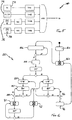
- Figure 6 shows a flow chart 80 for operations within the autoinjector of Figure 4 .
- the flowchart starts with Initialisation at step 82 and begins with a negative output, X at step 83, so no injection operation occurs.
- the first test occurs at step 84 when the output from the ambient light sensor 60 is checked against a threshold. If above the threshold (Y) then the IR source is turned on in step 86 and a skin test (ST) conducted.
- the skin test is a check of the output from the skin sensor 20. A positive output from the skin sensor 20 is a 1, indicating skin has been detected, and a negative output is a 0.
- a timer is reset to zero (TR) in step 85 and a further skin test (ST) carried out in step 87.
- the timer is checked in step 88 and, if the timer indicates a time of more than 0.2s since the timer reset (TR) then a positive output is generated in step 90 indicating that the autoinjector can now carry out an injection cycle, or at least move on to the next operation.
- further skin tests are conducted to ensure that a positive output is still appropriate. If the further skin test is positive then the positive output in step 90 is maintained and a loop is entered.
- step 92 if the skin test (ST) is negative then a negative output is generated in step 92 and the flowchart returns to a point as if the skin test (ST) at step 87 had been negative.
- the timer is again reset (TR) and a skin test (ST) conducted.
- a positive output from this skin test (ST) returns the process to the timer rest of step 85.
- a negative output moves the process to step 94 in which the timer is checked and, if the timer indicates a time of more than 2s since the last timer reset (TR) then a positive output is generated in step 94.
- a negative output from step 94 returns the process to the skin test (ST) step.
- a positive output in step 94 results in the IR source being powered down in step 96 and the process returning to a negative output being generated in step 83.
- This flowchart results in a positive output in step 90 only if a positive skin test is positive each time it is checked for at least 0.2s and will remain positive only for as long as the skin test results remain positive.
- the IR source is turned off to save energy and the ambient light levels are checked in step 84 to ensure that the autoinjector is still located against a surface.
Landscapes
- Health & Medical Sciences (AREA)
- Life Sciences & Earth Sciences (AREA)
- General Health & Medical Sciences (AREA)
- Physics & Mathematics (AREA)
- Pathology (AREA)
- Immunology (AREA)
- General Physics & Mathematics (AREA)
- Biochemistry (AREA)
- Analytical Chemistry (AREA)
- Chemical & Material Sciences (AREA)
- Heart & Thoracic Surgery (AREA)
- Veterinary Medicine (AREA)
- Public Health (AREA)
- Animal Behavior & Ethology (AREA)
- Hematology (AREA)
- Biomedical Technology (AREA)
- Anesthesiology (AREA)
- Engineering & Computer Science (AREA)
- Vascular Medicine (AREA)
- Optics & Photonics (AREA)
- Infusion, Injection, And Reservoir Apparatuses (AREA)
Description
- The present invention relates to an autoinjector comprising an electronic sensor for detecting skin, particularly a reconstituting autoinjector.
- Some medicaments are administered to a patient by injecting a liquid formulation of the medicament into the patient. This is typically performed using a needle coupled to a syringe. In some cases the liquid formulation is not stable in the liquid form and is supplied as a dried medicament and a reconstituting liquid. Prior to injection the reconstituting liquid is added to the dried medicament to create the injectable liquid formulation. It is known to use an autoinjector to automate at least part of the process of injecting a patient, such as a human or animal. Automation of the injection step is particularly useful where a consistent depth and / or volume of injection is desirable.
- It may be desirable to avoid unwanted activation of an automatic injection operation. It may be desirable for injection to occur into, or through, the skin of a patient and a means of detecting proximity to an object to be injected has been included in some autoinjectors. In some cases a mechanical probe has been used to detect a surface to be injected, in other cases a capacitive sensor has been used to detect contact with skin prior to injection.
-
WO2009/037432 discloses a device for determining the location and orientation of a vein under the skin of a patient. This device is not coupled to an autoinjector.US2012/116212 teaches an autoinjector having generic sensors, which sensors relate to the operation of the injector itself. - The present invention is defined in
independent claim 1. Preferred embodiments are defined in the dependent claims. - When light, particularly infrared (IR) light, is shone into the surface of a highly scattering material (such as a body tissue like fat or muscle, or a combination of the two), the photons are both absorbed and scattered in multiple directions in a process that can be modelled statistically. The result of this scattering is that a bright path (high relative average photon density) will exist within the material, and that the light will be detected at the material surface some distance from the source. The profile of light intensity at the material surface as a function of distance from the source is characteristic of the scattering material. Providing two detectors at different distances from the source means that the difference between intensity of light at each of the detectors is indicative of the characteristic of the material and this difference can therefore be used to determine whether the material into which the light is being shone has the light scattering characteristic of a body tissue into which an injection can occur.
- In the sensor according to the invention an EM source illuminates the surface of the material to be tested with electromagnetic (EM) radiation, while two detectors measure the intensity of EM radiation emerging from the material in two positions at different distances from the source. The EM source may emit infrared radiation in the infrared spectrum between wavelengths of about 0.7 micrometres and about 300 micrometres.
- The sensor is intended to test for the presence of tissue into which an injection can be made. A positive reading from the sensor can be taken as indicator that the sensor is in close proximity to skin. The first sensor may be positioned at the expected bright-spot for suitable tissue and the second sensor may be positioned adjacent to it as this will provide the biggest difference in signal strengths between the first and second sensors. Although the transmission of the EM radiation through the tissue is an important characteristic living tissue is not of a consistent character and the characteristic will vary at different sites around the body. For example muscle and fat will have a different scattering characteristic. In order for the sensor to produce a positive skin signal the EM radiation emitted from the source must be detected by the sensors after it has passed through a medium. As mentioned above, the scattering characteristic of tissues varies so when the sensor is in close proximity or contact with a tissue with a scattering characteristic as determined by the processing of the two signals from the detectors that matches a scattering characteristic determined for tissue into which an injection can occur the sensor is able to generate a skin signal.
- It should be understood that the term skin in this document is intended to refer to tissue into which an injection can occur, for example fat, muscle or other body tissue and not simply human or animal skin. Since the human or animal body is typically substantially covered in skin it can usually be assumed that if the sensor detects such tissue, it is in contact with, or close proximity to, skin.
- Providing a small source can facilitate the determination of the characteristic so the EM source may be substantially a point source, or a source small enough to be considered substantially equivalent to one. This could be achieved by providing a plate opaque to the emitted EM radiation through which there is a pin-hole between the EM source and the material to be tested. The pin hole may be less than 5mm, less than 2.5mm or less than 1.5mm. The pinhole may be between about 1.5mm and 1mm. For these dimensions it is intended that the dimension refers to a diameter, or maximum dimension of the aperture for apertures that are not substantially circular in shape.
- The baffle is intended to prevent a direct light path from the EM source to either of the detectors. The baffle may be substantially planar, curved, or a combination of the two. The baffle may substantially surround the EM source. The baffle, first EM detector and second EM detector may be arranged substantially in a straight line.
- If the EM source emits IR radiation, the sensor may include a cover of IR transmitting glass. Such a cover could protect the sensor from dirt contamination or physical damage. Such a cover should cover one or more of the emitter and detectors and more than one cover may be provided.
- In order to generate a skin signal which is indicative of whether the sensor has detected skin the processor compares the first signal strength with a first threshold to determine if the signal is strong enough to indicate that the sensor is in contact, or at least close proximity, to an IR transmissive material that has an IR scattering characteristic that is indicative of being a material into which an injection can be made. Furthermore, the processor compares the ratio between the first and second signals with a second threshold to determine whether the material has an IR scattering characteristic that is indicative of being a material into which an injection can be made.
- The processor monitors the rate of change of the first and second signals in time and compares that rate of change with a threshold to determine whether the signals are stable as this may assist in preventing the generation of false positive skin signals.
- It should be understood that the thresholds mentioned above will depend upon many factors, for example the EM radiation being used, the location of the skin to be detected, the risk of false positives or false negatives that can be tolerated. It should be possible to set suitable limits using basic trial and error methods.
- The IR source may be an Infra Red LED, or any other suitable source and the IR detectors may be photodiodes capable of detecting incident IR radiation intensity, or any other suitable detector capable of generating a signal indicative of the intensity of IR light reaching the detector. In one example the wavelength of EM radiation used is between 900 and 1000nm.
- The distance between the IR source and the first sensor may be between 0.1cm and 0.6cm, between 0.2cm and 0.5cm or may be substantially 0.3cm. The difference in the distance from the EM source between the first sensor and the second sensor may be between 0.1cm and 1cm, between 0.2cm and 0.7cm or between about 0.3cm and 0.5cm. This distance may be the distance between the two detectors if the detectors are positioned along a substantially straight line from the source to the first detector and then the second detector. However, since the scattering within the tissue is not limited to a single line, but radiates from the source so the detectors need not be arranged along a line extending through the emitter.
- The autoinjector according to the invention comprises a liquid container, an injector, an injection contact portion, a processor and a sensor adjacent the injection contact portion, wherein the injector is arranged to inject liquid from the liquid container into a patient at the injection contact portion, the sensor being substantially as described above and the autoinjector being configured to use the injector to inject the liquid from the container into a subject only when a positive skin signal has been received from the sensor.
- The autoinjector may include an ambient light sensor adjacent the sensor and the autoinjector may be configured to activate the sensor only when the ambient light sensor detects ambient light levels below a threshold level.
- The autoinjector may be a reconstituting autoinjector which is capable of receiving a dry medicament product and a reconstitution liquid, automatically combining them to provide an injectable medication and subsequently automatically injecting them into a patient. There may be user steps to complete before, during or after each of the automated steps.
- The invention will now be further described, by way of example only, with reference to the following drawings in which:
-
Figure 1 shows a graph of IR light intensity against distance from a source at the surface of a material; -
Figure 2 shows a schematic of light intensity within a material; -
Figure 3 shows a sensor; -
Figure 4 shows an autoinjector comprising a sensor; -
Figure 5 shows a logic gate for use in the sensor ofFigure 3 ; and -
Figure 6 shows a flowchart for operations within the autoinjector ofFigure 4 . -
Figure 1 shows agraph 1 with light intensity (I) on thevertical axis 2 and distance from a light source (x) on the horizontal axis 4. Thegraph 1 shows how the light intensity (I) varies as a function of distance (x) from the source. It can be seen from thegraph 1 that the light intensity (I) initially falls with increasing distance from the source, but then rises to a maximum at the point D1 from the source before falling again. The distance D1 is indicative of a characteristic of the light scattering properties of a material into which the light is being shone. In this case the light is an IR light. -
Figure 2 shows a schematic of the light intensity within a material 6 when a portion 8 of asurface 10 is illuminated withIR light 12. Due to light scattering within the material 6 a 'bright path' 14 is established within the material 6 in which the average light intensity is relatively higher than elsewhere. The bright path 14 is bounded by alower intensity path 16. The bright path 14 curves through the material from the illuminated surface portion 8 until it reaches thesurface 10 again at a point a distance D1 from the illuminated portion 8. -
Figure 3 shows anelectronic sensor 20 for detectingskin 22, thesensor 20 comprisesprocessor 24, anIR source 26, in this case an Infra Red emitting LED, abaffle 28, afirst IR detector 30 and asecond IR detector 32, in this case photo diodes. TheIR source 26 includes anopaque plate 40 through which there is a pinhole 42 so that the IR source projects a fine point of IR light. The diameter of the pinhole may be less than 2mm, may be less than 1mm or may be less than 0.5mm. The optical power emerging through the pin hole is approximately 14 mW. - The sensor further includes a
cover 44 of a material through which IR radiation can pass. Thecover 44 is arranged to cover theIR source 26,baffle 28,first IR detector 30 andsecond IR detector 32. - The
sensor 20 is arranged such that theIR source 26 is located on afirst side 34 of thebaffle 28 and the first andsecond IR detectors baffle 28 at first and second distances D1,D2 from theIR source 26 respectively. Thebaffle 28 prevents IR light from passing directly from theIR source 26 to thedetectors IR source 26 and the point at which the bright path mentioned above reaches the surface of flesh, or other suitable body tissue, covered by skin. TheIR source 24,baffle 28, first andsecond detectors - The
processor 24 is configured to selectively cause theIR source 26 to emit IR radiation and to receive first and second signals S1,S2 from the first andsecond IR detectors sensor 20 further includes a power source 38 to provide power the various components. The power source 38 may be integral with the sensor, or external. The signals received are indicative of the intensity of IR radiation detected by eachsensor -
Figure 4 shows an autoinjector 50 comprising a liquid container 52, aninjector 54, an injection contact portion 56,processor 58 and asensor 20 adjacent the injection contact portion 56. Theinjector 54 is arranged to inject liquid from the liquid container 52 into a patient at the site of the injection contact portion 56. The autoinjector 50 is configured to use theinjector 54 to inject the liquid into a subject only when a positive skin signal has been received from thesensor 20. - The autoinjector 50 further includes an ambient
light sensor 60 adjacent thesensor 20 for measuring the intensity of the ambient light. The autoinjector 50 further comprises apower source 62. It should be noted that either, both or neither theprocessor 58 and thepower source 62 may be integral with the power source 38 andprocessor 24 of thesensor 20 and be located within, or external to thesensor 20. - In this case the liquid container 52 is a syringe which is coupled to a
needle 64 through which liquid can be injected. Theinjector 54 comprises drive means 66 which can be operated to force liquid from the container 52 through theneedle 64. Theinjector 54 is also operable to move theneedle 64 out of the autoinjector 50 at the injection contact portion 56 so that, if the autoinjector 50 is located with the injection contact portion 56 against the skin of a patient, the autoinjector can inject the liquid into a patient through theneedle 64. -
Figure 5 shows a logic gate 70 suitable for use in the sensor ofFigure 3 . The logic gate 70 is an AND gate with fourinputs first sensor 30. The signal S1 is checked against a threshold THR1 and, if S1 is greater than THR1, a positive signal is passed to the logic gate 70. - The
second input 74 is the ratio of the signal S1 from thefirst sensor 30 divided by the signal S2 from thesecond sensor 32. The resulting ratio S1/S2 is checked against a threshold THR2 and, if greater than THR2, a positive signal is passed to the logic gate 70. It has been found that the ratio of S1/S2 is between about 2 and 6 when the sensor is in contact with skin. Therefore THR2 may be at least 2. - The third and
fourth inputs - If the AND Gate 70 receives a positive signal as a result of all the four
inputs inputs -
Figure 6 shows aflow chart 80 for operations within the autoinjector ofFigure 4 . The flowchart starts with Initialisation atstep 82 and begins with a negative output, X atstep 83, so no injection operation occurs. The first test occurs at step 84 when the output from the ambientlight sensor 60 is checked against a threshold. If above the threshold (Y) then the IR source is turned on instep 86 and a skin test (ST) conducted. The skin test is a check of the output from theskin sensor 20. A positive output from theskin sensor 20 is a 1, indicating skin has been detected, and a negative output is a 0. - In the event of a positive output a timer is reset to zero (TR) in step 85 and a further skin test (ST) carried out in step 87. In the event of another positive output the timer is checked in step 88 and, if the timer indicates a time of more than 0.2s since the timer reset (TR) then a positive output is generated in
step 90 indicating that the autoinjector can now carry out an injection cycle, or at least move on to the next operation. Following the generation of a positive output instep 90 further skin tests (ST) are conducted to ensure that a positive output is still appropriate. If the further skin test is positive then the positive output instep 90 is maintained and a loop is entered. - However, if the skin test (ST) is negative then a negative output is generated in
step 92 and the flowchart returns to a point as if the skin test (ST) at step 87 had been negative. The timer is again reset (TR) and a skin test (ST) conducted. A positive output from this skin test (ST) returns the process to the timer rest of step 85. A negative output moves the process to step 94 in which the timer is checked and, if the timer indicates a time of more than 2s since the last timer reset (TR) then a positive output is generated instep 94. A negative output fromstep 94 returns the process to the skin test (ST) step. A positive output instep 94 results in the IR source being powered down instep 96 and the process returning to a negative output being generated instep 83. - This flowchart results in a positive output in
step 90 only if a positive skin test is positive each time it is checked for at least 0.2s and will remain positive only for as long as the skin test results remain positive. - However if a consistent negative skin test is returned for at least 2s then the IR source is turned off to save energy and the ambient light levels are checked in step 84 to ensure that the autoinjector is still located against a surface.
- It should be understood that the flowchart described above is only a possible way in which the device could be arranged to operate and there may be modifications within the scope of the appended
Claims (8)
- An autoinjector (50) comprising a liquid container (52), an injector (54), an injection contact portion (56), a processor (58) and an electronic sensor (20) adjacent the injection contact portion (56) for detecting skin, the injector (54) is arranged to inject liquid from the liquid container (52) into a patient at the injection contact portion (56), the electronic sensor (20) comprising a processor (24), an EM source (26) is configured to project a fine point of IR light onto the skin of a patient, a baffle (28), a first EM detector (30) and a second EM detector (32), the sensor (20) being arranged such that the EM source (26) is located on a first side (34) of the baffle and the first and second EM detectors (30,32) are arranged on a second, opposite, side (36) of the baffle (28) at first and second distances from the EM source (26) respectively, the first distance being less than the second distance, wherein the processor (24) is configured to cause the source (26) to emit EM radiation and to receive first and second signals from the first and second EM detectors (30,32) respectively, the signals being indicative of the intensity of EM radiation detected by the sensor at a surface of the skin, the processor (24) being further configured to process the first and second signals wherein the first signal is input to a logic gate and is compared against a first threshold, and if greater, a positive signal is passed to the logic gate; said first signal is divided by said second signal, and compared to a second threshold, and if greater a positive signal is passed to the logic gate; a rate of change of each of said first and second signals with respect to time is obtained and compared to a third and a fourth threshold respectively, and a positive signal is passed to the logic gate if the rate of change of said first and second signals is below said third and fourth thresholds, and wherein if the logic gate receives a summation of all four positive signals generates a positive skin detection signal, and wherein the autoinjector (50) is configured to use the injector (54) to inject the liquid from the container (52) into a patient only when a positive skin signal has been received from the sensor (20).
- An autoinjector as claimed in claim 1, in which the EM source (26) is a pinhole source.
- An autoinjector as claimed in claim 1 or claim 2, in which the EM source (26), the baffle (28), first EM detector (30) and second EM detector (32) are arranged substantially in a straight line.
- An autoinjector as claimed in any preceding claim, in which the sensor (20) includes a cover (44) of EM transmitting glass.
- An autoinjector as claimed in claim 1, in which the EM source (26) is an Infra Red LED and the EM detectors (30, 32) are photodiodes.
- An autoinjector as claimed in any preceding claim, in which the distance between the EM source (26) and the first sensor (30) is between 0.1cm and 0.6cm.
- An autoinjector as claimed in any preceding claim, in which the distance between the first sensor (30) and the second sensor (32) is between 0.1cm and 1cm.
- An autoinjector as claimed in any preceding claim, in which the autoinjector includes an ambient light sensor (60) adjacent the sensor (20) and the autoinjector is configured to activate the sensor (20) only when the ambient light sensor (60) detects ambient light levels below a threshold level.
Applications Claiming Priority (2)
| Application Number | Priority Date | Filing Date | Title |
|---|---|---|---|
| US201161466193P | 2011-03-22 | 2011-03-22 | |
| PCT/EP2012/054927 WO2012126915A1 (en) | 2011-03-22 | 2012-03-20 | Sensor |
Publications (2)
| Publication Number | Publication Date |
|---|---|
| EP2688464A1 EP2688464A1 (en) | 2014-01-29 |
| EP2688464B1 true EP2688464B1 (en) | 2020-10-14 |
Family
ID=46017788
Family Applications (1)
| Application Number | Title | Priority Date | Filing Date |
|---|---|---|---|
| EP12717204.7A Active EP2688464B1 (en) | 2011-03-22 | 2012-03-20 | Autoinjector with infrared sensor |
Country Status (4)
| Country | Link |
|---|---|
| US (1) | US9415167B2 (en) |
| EP (1) | EP2688464B1 (en) |
| ES (1) | ES2842972T3 (en) |
| WO (1) | WO2012126915A1 (en) |
Families Citing this family (3)
| Publication number | Priority date | Publication date | Assignee | Title |
|---|---|---|---|---|
| CN112237662B (en) | 2014-06-03 | 2022-10-21 | 安姆根有限公司 | Drug delivery system and method of use |
| CN109689132B (en) * | 2016-09-09 | 2022-06-21 | 赛诺菲-安万特德国有限公司 | Reading device, drug delivery device and combination of drug delivery device and reading device |
| JP7369695B2 (en) * | 2018-07-25 | 2023-10-26 | 株式会社ダイセル | Measurement system, measurement method |
Citations (1)
| Publication number | Priority date | Publication date | Assignee | Title |
|---|---|---|---|---|
| US20120116212A1 (en) * | 2010-11-08 | 2012-05-10 | Pourang Bral | Injectable solution container and syringe |
Family Cites Families (7)
| Publication number | Priority date | Publication date | Assignee | Title |
|---|---|---|---|---|
| JP3433534B2 (en) | 1994-11-07 | 2003-08-04 | 浜松ホトニクス株式会社 | Method and apparatus for measuring scattering and absorption characteristics in scattering medium |
| US6353226B1 (en) * | 1998-11-23 | 2002-03-05 | Abbott Laboratories | Non-invasive sensor capable of determining optical parameters in a sample having multiple layers |
| DK1773978T3 (en) * | 2004-05-19 | 2014-05-26 | Univ Pittsburgh | Perfused, three-dimensional cell / tissue disease models |
| US7722562B2 (en) * | 2006-03-02 | 2010-05-25 | Tyco Healthcare Group Lp | Pump set with safety interlock |
| WO2009037432A1 (en) | 2007-09-18 | 2009-03-26 | Talley Group Limited | Device and method for locating veins or arteries |
| JP2009227809A (en) * | 2008-03-21 | 2009-10-08 | Fujifilm Corp | Hydrophilic composition and hydrophilic treating member |
| US7884933B1 (en) * | 2010-05-05 | 2011-02-08 | Revolutionary Business Concepts, Inc. | Apparatus and method for determining analyte concentrations |
-
2012
- 2012-03-20 WO PCT/EP2012/054927 patent/WO2012126915A1/en not_active Ceased
- 2012-03-20 ES ES12717204T patent/ES2842972T3/en active Active
- 2012-03-20 EP EP12717204.7A patent/EP2688464B1/en active Active
- 2012-03-20 US US14/006,124 patent/US9415167B2/en active Active
Patent Citations (1)
| Publication number | Priority date | Publication date | Assignee | Title |
|---|---|---|---|---|
| US20120116212A1 (en) * | 2010-11-08 | 2012-05-10 | Pourang Bral | Injectable solution container and syringe |
Also Published As
| Publication number | Publication date |
|---|---|
| EP2688464A1 (en) | 2014-01-29 |
| ES2842972T3 (en) | 2021-07-15 |
| US9415167B2 (en) | 2016-08-16 |
| US20140018768A1 (en) | 2014-01-16 |
| WO2012126915A1 (en) | 2012-09-27 |
Similar Documents
| Publication | Publication Date | Title |
|---|---|---|
| US8874194B2 (en) | Leak detecting apparatus | |
| JP7055432B2 (en) | System to collect injection information | |
| CN103889316B (en) | Ophthalmic device and method for measuring eyes | |
| WO2016050486A1 (en) | Optical vital signs sensor. | |
| CN202289094U (en) | Transfusion alarm | |
| US9415167B2 (en) | Infrared skin detection sensor | |
| WO2016027202A3 (en) | Device, system and method for non-invasively measuring blood glucose | |
| US9934589B2 (en) | System and method for determining bilirubin levels in newborn babies | |
| KR101931457B1 (en) | Apparatus and method for protecting a user from blue light radiation | |
| RU2468356C2 (en) | Diode laser device for non-invasive measurement of glycaemia | |
| CN104941037A (en) | Infusion alarm apparatus based on optical total reflection principle | |
| US20140303474A1 (en) | Device to Aid in Diagnosing Infiltration or Extravasation in Animalia Tissue | |
| Patade et al. | IOT solutions for hospitals | |
| CN212568475U (en) | Living body detection device based on skin transmitted light collection | |
| KR101789122B1 (en) | Fluoroscopic apparatus and method using a sensor | |
| Zhao et al. | Wireless photoplethysmograph knuckle sensor system for measuring finger motions | |
| CN111766223A (en) | A living body detection device and method based on skin transmitted light collection | |
| Stewart et al. | Assessment of a low-cost LED vein detection method: Initial proof of concept | |
| KR102735328B1 (en) | Device for simultaneous measurement of urine flowmetry and urine chemistry using optics | |
| CN107025417A (en) | Electronic installation | |
| CN204832023U (en) | Quick detection device of soil moisture based on near infrared spectroscopy | |
| WO2016002356A1 (en) | Measurement device | |
| JP6705593B2 (en) | measuring device | |
| JPWO2016002363A1 (en) | measuring device |
Legal Events
| Date | Code | Title | Description |
|---|---|---|---|
| PUAI | Public reference made under article 153(3) epc to a published international application that has entered the european phase |
Free format text: ORIGINAL CODE: 0009012 |
|
| 17P | Request for examination filed |
Effective date: 20131022 |
|
| AK | Designated contracting states |
Kind code of ref document: A1 Designated state(s): AL AT BE BG CH CY CZ DE DK EE ES FI FR GB GR HR HU IE IS IT LI LT LU LV MC MK MT NL NO PL PT RO RS SE SI SK SM TR |
|
| DAX | Request for extension of the european patent (deleted) | ||
| RAP1 | Party data changed (applicant data changed or rights of an application transferred) |
Owner name: NOVARTIS AG |
|
| RIN1 | Information on inventor provided before grant (corrected) |
Inventor name: HAYES, MATTHEW Inventor name: TROOP, NICHOLAS Inventor name: RYDER, PAUL DAVID Inventor name: SCHMIDLIN ALAIN |
|
| RIN1 | Information on inventor provided before grant (corrected) |
Inventor name: SCHMIDLIN ALAIN Inventor name: HAYES, MATTHEW Inventor name: RYDER, PAUL DAVID Inventor name: TROOP, NICHOLAS |
|
| STAA | Information on the status of an ep patent application or granted ep patent |
Free format text: STATUS: EXAMINATION IS IN PROGRESS |
|
| 17Q | First examination report despatched |
Effective date: 20190702 |
|
| REG | Reference to a national code |
Ref country code: DE Ref legal event code: R079 Ref document number: 602012072781 Country of ref document: DE Free format text: PREVIOUS MAIN CLASS: A61B0005000000 Ipc: A61M0005200000 |
|
| GRAP | Despatch of communication of intention to grant a patent |
Free format text: ORIGINAL CODE: EPIDOSNIGR1 |
|
| STAA | Information on the status of an ep patent application or granted ep patent |
Free format text: STATUS: GRANT OF PATENT IS INTENDED |
|
| RIC1 | Information provided on ipc code assigned before grant |
Ipc: G01N 21/35 20140101ALN20200421BHEP Ipc: A61B 5/1495 20060101ALI20200421BHEP Ipc: A61M 5/20 20060101AFI20200421BHEP Ipc: G01N 21/47 20060101ALI20200421BHEP Ipc: A61M 5/42 20060101ALN20200421BHEP Ipc: A61M 5/00 20060101ALI20200421BHEP |
|
| INTG | Intention to grant announced |
Effective date: 20200520 |
|
| GRAS | Grant fee paid |
Free format text: ORIGINAL CODE: EPIDOSNIGR3 |
|
| GRAA | (expected) grant |
Free format text: ORIGINAL CODE: 0009210 |
|
| STAA | Information on the status of an ep patent application or granted ep patent |
Free format text: STATUS: THE PATENT HAS BEEN GRANTED |
|
| AK | Designated contracting states |
Kind code of ref document: B1 Designated state(s): AL AT BE BG CH CY CZ DE DK EE ES FI FR GB GR HR HU IE IS IT LI LT LU LV MC MK MT NL NO PL PT RO RS SE SI SK SM TR |
|
| REG | Reference to a national code |
Ref country code: GB Ref legal event code: FG4D |
|
| REG | Reference to a national code |
Ref country code: AT Ref legal event code: REF Ref document number: 1322974 Country of ref document: AT Kind code of ref document: T Effective date: 20201015 Ref country code: CH Ref legal event code: EP |
|
| REG | Reference to a national code |
Ref country code: DE Ref legal event code: R096 Ref document number: 602012072781 Country of ref document: DE |
|
| REG | Reference to a national code |
Ref country code: IE Ref legal event code: FG4D |
|
| REG | Reference to a national code |
Ref country code: AT Ref legal event code: MK05 Ref document number: 1322974 Country of ref document: AT Kind code of ref document: T Effective date: 20201014 |
|
| REG | Reference to a national code |
Ref country code: NL Ref legal event code: MP Effective date: 20201014 |
|
| PG25 | Lapsed in a contracting state [announced via postgrant information from national office to epo] |
Ref country code: FI Free format text: LAPSE BECAUSE OF FAILURE TO SUBMIT A TRANSLATION OF THE DESCRIPTION OR TO PAY THE FEE WITHIN THE PRESCRIBED TIME-LIMIT Effective date: 20201014 Ref country code: RS Free format text: LAPSE BECAUSE OF FAILURE TO SUBMIT A TRANSLATION OF THE DESCRIPTION OR TO PAY THE FEE WITHIN THE PRESCRIBED TIME-LIMIT Effective date: 20201014 Ref country code: PT Free format text: LAPSE BECAUSE OF FAILURE TO SUBMIT A TRANSLATION OF THE DESCRIPTION OR TO PAY THE FEE WITHIN THE PRESCRIBED TIME-LIMIT Effective date: 20210215 Ref country code: NL Free format text: LAPSE BECAUSE OF FAILURE TO SUBMIT A TRANSLATION OF THE DESCRIPTION OR TO PAY THE FEE WITHIN THE PRESCRIBED TIME-LIMIT Effective date: 20201014 Ref country code: NO Free format text: LAPSE BECAUSE OF FAILURE TO SUBMIT A TRANSLATION OF THE DESCRIPTION OR TO PAY THE FEE WITHIN THE PRESCRIBED TIME-LIMIT Effective date: 20210114 Ref country code: GR Free format text: LAPSE BECAUSE OF FAILURE TO SUBMIT A TRANSLATION OF THE DESCRIPTION OR TO PAY THE FEE WITHIN THE PRESCRIBED TIME-LIMIT Effective date: 20210115 |
|
| REG | Reference to a national code |
Ref country code: LT Ref legal event code: MG4D |
|
| PG25 | Lapsed in a contracting state [announced via postgrant information from national office to epo] |
Ref country code: SE Free format text: LAPSE BECAUSE OF FAILURE TO SUBMIT A TRANSLATION OF THE DESCRIPTION OR TO PAY THE FEE WITHIN THE PRESCRIBED TIME-LIMIT Effective date: 20201014 Ref country code: PL Free format text: LAPSE BECAUSE OF FAILURE TO SUBMIT A TRANSLATION OF THE DESCRIPTION OR TO PAY THE FEE WITHIN THE PRESCRIBED TIME-LIMIT Effective date: 20201014 Ref country code: IS Free format text: LAPSE BECAUSE OF FAILURE TO SUBMIT A TRANSLATION OF THE DESCRIPTION OR TO PAY THE FEE WITHIN THE PRESCRIBED TIME-LIMIT Effective date: 20210214 Ref country code: LV Free format text: LAPSE BECAUSE OF FAILURE TO SUBMIT A TRANSLATION OF THE DESCRIPTION OR TO PAY THE FEE WITHIN THE PRESCRIBED TIME-LIMIT Effective date: 20201014 Ref country code: BG Free format text: LAPSE BECAUSE OF FAILURE TO SUBMIT A TRANSLATION OF THE DESCRIPTION OR TO PAY THE FEE WITHIN THE PRESCRIBED TIME-LIMIT Effective date: 20210114 Ref country code: AT Free format text: LAPSE BECAUSE OF FAILURE TO SUBMIT A TRANSLATION OF THE DESCRIPTION OR TO PAY THE FEE WITHIN THE PRESCRIBED TIME-LIMIT Effective date: 20201014 |
|
| PG25 | Lapsed in a contracting state [announced via postgrant information from national office to epo] |
Ref country code: HR Free format text: LAPSE BECAUSE OF FAILURE TO SUBMIT A TRANSLATION OF THE DESCRIPTION OR TO PAY THE FEE WITHIN THE PRESCRIBED TIME-LIMIT Effective date: 20201014 |
|
| REG | Reference to a national code |
Ref country code: DE Ref legal event code: R097 Ref document number: 602012072781 Country of ref document: DE Ref country code: ES Ref legal event code: FG2A Ref document number: 2842972 Country of ref document: ES Kind code of ref document: T3 Effective date: 20210715 |
|
| PG25 | Lapsed in a contracting state [announced via postgrant information from national office to epo] |
Ref country code: RO Free format text: LAPSE BECAUSE OF FAILURE TO SUBMIT A TRANSLATION OF THE DESCRIPTION OR TO PAY THE FEE WITHIN THE PRESCRIBED TIME-LIMIT Effective date: 20201014 Ref country code: SK Free format text: LAPSE BECAUSE OF FAILURE TO SUBMIT A TRANSLATION OF THE DESCRIPTION OR TO PAY THE FEE WITHIN THE PRESCRIBED TIME-LIMIT Effective date: 20201014 Ref country code: LT Free format text: LAPSE BECAUSE OF FAILURE TO SUBMIT A TRANSLATION OF THE DESCRIPTION OR TO PAY THE FEE WITHIN THE PRESCRIBED TIME-LIMIT Effective date: 20201014 Ref country code: EE Free format text: LAPSE BECAUSE OF FAILURE TO SUBMIT A TRANSLATION OF THE DESCRIPTION OR TO PAY THE FEE WITHIN THE PRESCRIBED TIME-LIMIT Effective date: 20201014 Ref country code: CZ Free format text: LAPSE BECAUSE OF FAILURE TO SUBMIT A TRANSLATION OF THE DESCRIPTION OR TO PAY THE FEE WITHIN THE PRESCRIBED TIME-LIMIT Effective date: 20201014 Ref country code: SM Free format text: LAPSE BECAUSE OF FAILURE TO SUBMIT A TRANSLATION OF THE DESCRIPTION OR TO PAY THE FEE WITHIN THE PRESCRIBED TIME-LIMIT Effective date: 20201014 |
|
| PLBE | No opposition filed within time limit |
Free format text: ORIGINAL CODE: 0009261 |
|
| STAA | Information on the status of an ep patent application or granted ep patent |
Free format text: STATUS: NO OPPOSITION FILED WITHIN TIME LIMIT |
|
| PG25 | Lapsed in a contracting state [announced via postgrant information from national office to epo] |
Ref country code: DK Free format text: LAPSE BECAUSE OF FAILURE TO SUBMIT A TRANSLATION OF THE DESCRIPTION OR TO PAY THE FEE WITHIN THE PRESCRIBED TIME-LIMIT Effective date: 20201014 |
|
| 26N | No opposition filed |
Effective date: 20210715 |
|
| PG25 | Lapsed in a contracting state [announced via postgrant information from national office to epo] |
Ref country code: MC Free format text: LAPSE BECAUSE OF FAILURE TO SUBMIT A TRANSLATION OF THE DESCRIPTION OR TO PAY THE FEE WITHIN THE PRESCRIBED TIME-LIMIT Effective date: 20201014 Ref country code: AL Free format text: LAPSE BECAUSE OF FAILURE TO SUBMIT A TRANSLATION OF THE DESCRIPTION OR TO PAY THE FEE WITHIN THE PRESCRIBED TIME-LIMIT Effective date: 20201014 |
|
| PG25 | Lapsed in a contracting state [announced via postgrant information from national office to epo] |
Ref country code: SI Free format text: LAPSE BECAUSE OF FAILURE TO SUBMIT A TRANSLATION OF THE DESCRIPTION OR TO PAY THE FEE WITHIN THE PRESCRIBED TIME-LIMIT Effective date: 20201014 |
|
| REG | Reference to a national code |
Ref country code: BE Ref legal event code: MM Effective date: 20210331 |
|
| PG25 | Lapsed in a contracting state [announced via postgrant information from national office to epo] |
Ref country code: IE Free format text: LAPSE BECAUSE OF NON-PAYMENT OF DUE FEES Effective date: 20210320 Ref country code: LU Free format text: LAPSE BECAUSE OF NON-PAYMENT OF DUE FEES Effective date: 20210320 |
|
| PG25 | Lapsed in a contracting state [announced via postgrant information from national office to epo] |
Ref country code: IS Free format text: LAPSE BECAUSE OF FAILURE TO SUBMIT A TRANSLATION OF THE DESCRIPTION OR TO PAY THE FEE WITHIN THE PRESCRIBED TIME-LIMIT Effective date: 20210214 |
|
| PG25 | Lapsed in a contracting state [announced via postgrant information from national office to epo] |
Ref country code: BE Free format text: LAPSE BECAUSE OF NON-PAYMENT OF DUE FEES Effective date: 20210331 |
|
| PG25 | Lapsed in a contracting state [announced via postgrant information from national office to epo] |
Ref country code: HU Free format text: LAPSE BECAUSE OF FAILURE TO SUBMIT A TRANSLATION OF THE DESCRIPTION OR TO PAY THE FEE WITHIN THE PRESCRIBED TIME-LIMIT; INVALID AB INITIO Effective date: 20120320 Ref country code: CY Free format text: LAPSE BECAUSE OF FAILURE TO SUBMIT A TRANSLATION OF THE DESCRIPTION OR TO PAY THE FEE WITHIN THE PRESCRIBED TIME-LIMIT Effective date: 20201014 |
|
| P01 | Opt-out of the competence of the unified patent court (upc) registered |
Effective date: 20230514 |
|
| PG25 | Lapsed in a contracting state [announced via postgrant information from national office to epo] |
Ref country code: MK Free format text: LAPSE BECAUSE OF FAILURE TO SUBMIT A TRANSLATION OF THE DESCRIPTION OR TO PAY THE FEE WITHIN THE PRESCRIBED TIME-LIMIT Effective date: 20201014 |
|
| PG25 | Lapsed in a contracting state [announced via postgrant information from national office to epo] |
Ref country code: TR Free format text: LAPSE BECAUSE OF FAILURE TO SUBMIT A TRANSLATION OF THE DESCRIPTION OR TO PAY THE FEE WITHIN THE PRESCRIBED TIME-LIMIT Effective date: 20201014 |
|
| PG25 | Lapsed in a contracting state [announced via postgrant information from national office to epo] |
Ref country code: MT Free format text: LAPSE BECAUSE OF FAILURE TO SUBMIT A TRANSLATION OF THE DESCRIPTION OR TO PAY THE FEE WITHIN THE PRESCRIBED TIME-LIMIT Effective date: 20201014 |
|
| PGFP | Annual fee paid to national office [announced via postgrant information from national office to epo] |
Ref country code: ES Payment date: 20250410 Year of fee payment: 14 |
|
| PGFP | Annual fee paid to national office [announced via postgrant information from national office to epo] |
Ref country code: CH Payment date: 20250401 Year of fee payment: 14 |
|
| REG | Reference to a national code |
Ref country code: CH Ref legal event code: U11 Free format text: ST27 STATUS EVENT CODE: U-0-0-U10-U11 (AS PROVIDED BY THE NATIONAL OFFICE) Effective date: 20260401 |
|
| PGFP | Annual fee paid to national office [announced via postgrant information from national office to epo] |
Ref country code: GB Payment date: 20260223 Year of fee payment: 15 |
|
| PGFP | Annual fee paid to national office [announced via postgrant information from national office to epo] |
Ref country code: DE Payment date: 20260218 Year of fee payment: 15 |
|
| PGFP | Annual fee paid to national office [announced via postgrant information from national office to epo] |
Ref country code: IT Payment date: 20260226 Year of fee payment: 15 |
|
| PGFP | Annual fee paid to national office [announced via postgrant information from national office to epo] |
Ref country code: FR Payment date: 20260223 Year of fee payment: 15 |