EP2688269A1 - Flipping mechanism for mobile electronic device - Google Patents
Flipping mechanism for mobile electronic device Download PDFInfo
- Publication number
- EP2688269A1 EP2688269A1 EP12177151.3A EP12177151A EP2688269A1 EP 2688269 A1 EP2688269 A1 EP 2688269A1 EP 12177151 A EP12177151 A EP 12177151A EP 2688269 A1 EP2688269 A1 EP 2688269A1
- Authority
- EP
- European Patent Office
- Prior art keywords
- section
- electronic device
- mobile electronic
- auxiliary section
- main screen
- Prior art date
- Legal status (The legal status is an assumption and is not a legal conclusion. Google has not performed a legal analysis and makes no representation as to the accuracy of the status listed.)
- Withdrawn
Links
- 230000007246 mechanism Effects 0.000 title claims description 65
- 239000002184 metal Substances 0.000 description 21
- 239000000463 material Substances 0.000 description 15
- 230000006870 function Effects 0.000 description 13
- 230000007704 transition Effects 0.000 description 12
- 238000000034 method Methods 0.000 description 10
- 239000004033 plastic Substances 0.000 description 9
- 230000008569 process Effects 0.000 description 6
- 230000000284 resting effect Effects 0.000 description 6
- 239000005060 rubber Substances 0.000 description 6
- 230000003213 activating effect Effects 0.000 description 3
- 239000000853 adhesive Substances 0.000 description 3
- 230000001070 adhesive effect Effects 0.000 description 3
- 230000008901 benefit Effects 0.000 description 3
- 239000010410 layer Substances 0.000 description 3
- 238000003466 welding Methods 0.000 description 3
- 230000004048 modification Effects 0.000 description 1
- 238000012986 modification Methods 0.000 description 1
- 239000011241 protective layer Substances 0.000 description 1
- 230000004044 response Effects 0.000 description 1
- 238000006467 substitution reaction Methods 0.000 description 1
Images













Classifications
-
- H—ELECTRICITY
- H04—ELECTRIC COMMUNICATION TECHNIQUE
- H04M—TELEPHONIC COMMUNICATION
- H04M1/00—Substation equipment, e.g. for use by subscribers
- H04M1/02—Constructional features of telephone sets
- H04M1/0202—Portable telephone sets, e.g. cordless phones, mobile phones or bar type handsets
- H04M1/0206—Portable telephones comprising a plurality of mechanically joined movable body parts, e.g. hinged housings
- H04M1/0208—Portable telephones comprising a plurality of mechanically joined movable body parts, e.g. hinged housings characterized by the relative motions of the body parts
- H04M1/0214—Foldable telephones, i.e. with body parts pivoting to an open position around an axis parallel to the plane they define in closed position
-
- H—ELECTRICITY
- H04—ELECTRIC COMMUNICATION TECHNIQUE
- H04M—TELEPHONIC COMMUNICATION
- H04M1/00—Substation equipment, e.g. for use by subscribers
- H04M1/02—Constructional features of telephone sets
- H04M1/0202—Portable telephone sets, e.g. cordless phones, mobile phones or bar type handsets
- H04M1/0206—Portable telephones comprising a plurality of mechanically joined movable body parts, e.g. hinged housings
- H04M1/0247—Portable telephones comprising a plurality of mechanically joined movable body parts, e.g. hinged housings comprising more than two body parts
-
- H—ELECTRICITY
- H04—ELECTRIC COMMUNICATION TECHNIQUE
- H04M—TELEPHONIC COMMUNICATION
- H04M2250/00—Details of telephonic subscriber devices
- H04M2250/16—Details of telephonic subscriber devices including more than one display unit
Definitions
- the present embodiments relate to a mobile electronic device achieving a larger display ratio as compared with the size of a device using a flipping mechanism.
- Conventional handheld devices concealed the keypad of the handheld device using a sliding mechanism by which the keypad would slide in and out of the body of the device. Such devices increased the size of the device when the keypad was in the "out" position. In addition, when the keypad is in the out position, the overall balance of the device is changed, resulting in the device feeling top-heavy to the user during typing on the keypad.
- a mobile electronic device 100 having four sections, a first auxiliary section 1, a main screen section 2, a second auxiliary section 5, and a back section 6.
- the first auxiliary section 1 includes a display screen 3.
- the display screen 3 may include a touch screen or other similar input device.
- the first auxiliary section 1 is connected at one end to the main screen section 2 and at an opposite end to the back section 6.
- Figure 1 illustrates, for example, hinges 10a-10c and a pin that connect the first auxiliary section 1 to the back section 6.
- the hinges may be rigid or flexible and may be made of metal, plastic, rubber, or other suitable material, for example.
- the first auxiliary section 1 may also be connected to the main screen section 2 and the back section 6 by way of other suitable connecting methods.
- the first auxiliary section 1 may be connected to the main screen section 2 and the back section 6 by way of flexible material, such as rubber, which bends as the sections move.
- the flexible material may be formed with a bend that flattens as the sections move.
- the second auxiliary section 5 includes a keyboard 7 ( Figure 6 ).
- the keyboard 7, in one embodiment, may be a tactile keyboard.
- the second auxiliary section 5 could also include an additional display screen or touch screen that may or may not function as a keyboard.
- the second auxiliary section 5 could include, in place of or in addition to the keyboard or display screen, a touchless input device implemented via image sensors or other light or movement sensors.
- the second auxiliary section 5 is connected at one end to the main screen section 2 and at an opposite end to the back section 6 by way of, for example, hinges similar to hinges 10a-10c and a pin ( Figure 2 ).
- the second auxiliary section 5 may also be connected to the main screen section 2 and the back section 6 by way of other suitable connecting mechanisms, such as the mechanisms described above with respect to the first auxiliary section 1.
- the microprocessor is used to implement functions executed on the mobile electronic device 100 and to implement the display and execution of the operating system of the mobile electronic device 100 on the display screen 3 and a display screen 4.
- the memory is used to store programs and functions that are executed by the microprocessor.
- the back section 6 may be of differing thickness such that one or more portions of the back section 6 is a first thickness, and one or more portions of the back section 6 is a second thickness, wherein the first thickness is greater than the second thickness.
- Such variations in thickness may render the device 100 more comfortable during use, when the device 100 is gripped by a user's hand(s). Further, such variations in thickness may provide a gripping surface for manipulating the device 100 between the open and closed positions.
- the main screen section 2 includes the display screen 4.
- the display screen 4 may be a touch screen or other suitable device that displays information and receives input from a user.
- the display screen 4 may display information independent of, or in concert with, the information displayed on display screen 3.
- the display screen 3 may be an extension of the display screen 4 such that the screen appears to be larger in size.
- the display screen 3 may display information in concert with the display screen 4, but without making the screen appear to be a larger size (e.g. a window open on the display screen 4 would not extend into the display screen 3, while a window would extend into the display screen 3 in the alternate embodiment).
- the display screen 4 and the display screen 3 are substantially flush and may include or may not include a protective layer that is disposed between the display screen 3 and the display screen 4.
- the display screen 3 may also display content and receive input from a user independent from, or related to, the content displayed on the display screen 4.
- the display screen 3 may display advertisements, location-based information, launch icons, or shortcut icons.
- the display screen 3 could include tabs allowing the user to switch between windows on the display screen 4.
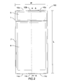
- Figure 2 illustrates a front facing view of the mobile electronic device 100. From the front facing view only the first auxiliary section 1 and the main screen section 2 are shown. Illustrated in Figure 2 are the hinges 10a-10c that connect the first auxiliary section 1 to the back section 6. Also illustrated in Figure 2 are hinges 11a-11c that connect the main screen section 2 to the back section 6.
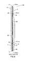
- FIG 3 illustrates a sectional view along the line A-A shown in Figure 2 .
- first auxiliary section 1, the main screen section 2, the second auxiliary section 5, and the back section 6 are shown.
- hinges 10a-c connecting the first auxiliary section 1 to the back section 6 and pin 14, which is disposed there-through.
- Hinges 13a-c with pin 17 there-through connect the first auxiliary section 1 to the main screen section 2.
- Hinges 12a-c and pin 16 there-through connect the back section 6 to the second auxiliary section 5 having the keyboard 7 thereon.
- Hinges 11a-c and pin 15 there-through connect the second auxiliary section 5 to the main screen section 2.
- a recess 20 is defined in a back side of the main screen section 2 (on the side that is opposite of the display screen 4).
- a recess 21 is defined in a back side of the back section 6 (on the side that is closest to the display screen 4).
- hinges 12a-c are resting in recess 22.
- the recess 22 provides space for hinges 12a-c and is defined in the back side of main screen section 2.
- Hinges 13a-c are resting in recess 19, which provides space for hinges 13a-c and is defined in the back side of back section 6.
- the recesses 19-22 enable a front face or first side of the device 100, including the main screen section 2 and either the first auxiliary section 1 or the second auxiliary section 5, to be positioned flat against a back face or second side of the device 100, including the back section 6 and either the first auxiliary section 1 or the second auxiliary section 5.
- Figure 4 illustrates a view of the mobile electronic device 100 in an open position as the device 100 transitions to the second state.
- the mobile electronic device 100 In the open position, the mobile electronic device 100 is in the process of switching from a first state to a second state.
- This switching is an example of the flipping mechanism.
- the first state is a state in which the first auxiliary section 1 and the main screen section 2 are on the first side of the device 100, and the back section 6 and the second auxiliary section 5 are on the second side of the device 100.
- the first and second sides are on opposite sides of the mobile electronic device 100.
- the second state is a state in which the second auxiliary section 5 and the main screen section 2 are on the first side of the device 100, and the back section 6 and the first auxiliary section 1 are on the second side of the device 100.
- the device 100 In the closed position, the device 100 has the same size footprint (length and width shown in Figure 2 ) in the first state and in the second state. Maintaining the same footprint in both the open and closed positions enables the device size to remain the same while providing large display/input areas, and prevents the device 100 from becoming too unwieldy.
- the display screen 3 or the keyboard or input device 7, respectively may be disabled.
- the display screen 3 or the keyboard 7 may be fully or partially enabled for input.
- the display screen 3 may be disabled for input, but enabled for display only.
- a touch screen keyboard may be displayed on the display screen 4 or on the display screen 3.
- the touch screen keyboard is displayed on the display screen 3 the image on the display screen 4 may be rotated.
- the display screen 4 and the display screen 3 may also be rotated independently or as a single unit in response to rotation of the device 100 by a user.
- the clasping mechanism 30/31 can be implemented using a magnet 30 or 31 and a metal plate 30 or 31. Alternatively, the clasping mechanism can be implemented using two magnets 30 and 31. The mechanism can also be implemented with three magnets, with two of the magnets being positioned on either the main screen section 2 or the back section 6. Alternatively, the clasping mechanism 30/31 can be implemented with two metal sections and one magnet or two magnets and one metal section, where the two metal sections or two magnets are positioned on either the main screen section 2 or the back section 6.
- the clasping mechanism 30/31 can also be implemented with a mechanical clasp having a hook or clasp made of metal or plastic.
- the clasping mechanism 30/31 can also be implemented with a pin or a pin having a ball on the end.
- the clasping mechanism 30/31 can be released by force of the user or by a mechanical release.
- the user when the device 100 is in the closed position, the user is able release the clasping mechanism 30/31 by pulling the main screen section 2 apart from the back section 6.
- the user when the device 100 is in the closed position, the user is able release the clasping mechanism 30/31 by activating a mechanical release, such as a button, which will disengage the clasping mechanism 30/31.
- a mechanical release such as a button
- the first auxiliary section 1 may split into two portions allowing the display screen 3 to partially separate from a core portion (e.g. element 50 in Figure 11 discussed below) of the first auxiliary section 1 and extend above the main screen section 2, such that, when in the second state, the first side would include the display screen 3, the display screen 4, and the keyboard 7 (not shown).
- the display screen 3 is able to flex/separate such that the display screen 3 is on the same side as the main display screen 4 and the keyboard 7, when the device 100 is in the second state (since in the first state, the keyboard is on the second/back side of the device 100).
- the display screen 3 could be connected to the core portion of the first auxiliary section 1 by a hinge, etc.
- the display screen 3 could be connected to the core portion of the first auxiliary section 1 by a clasp or a magnetic holding device.
- a similar alternate embodiment could be implemented for the keyboard 7 and the second auxiliary section 5.
- the main screen section 2 and the back section 6 could be directly connected to each other, without the first auxiliary section 1 connected therebetween.
- the main screen section 2 and the back section 6 form a top portion.
- the first auxiliary section 1 and second auxiliary section 5 could be disposed back to back such that the first auxiliary section 1 and the second auxiliary section 5 are directly connected without the back section 6 therebetween.
- the first auxiliary section 1 and the second auxiliary section 5 would form a bottom portion. The bottom portion could rotate with respect to the top portion so that the keyboard 7 is below the display screen 4 in one state, and the display screen 3 is below the display screen 4 in another state.
- Figure 5 illustrates another view of the mobile electronic device 100 in the open position as the device 100 continues to transition to the second state.
- the mobile electronic device 100 may rest on its side to maintain an upright position for viewing purposes.
- the display screen 3 or the keyboard 7 may be disabled or may be enabled.
- the power or input connectors for the mobile electronic device 100 may be on a side 40 of the device, on a bottom 41 of the main screen section 2 or a bottom 42 of the back section 6.
- Figure 6 illustrates another view of the mobile electronic device 100.
- the display screen 4 and the keyboard 7 are presented to the user.
- the main screen section 2 and the second auxiliary section 5 are on the first side of the device 100, corresponding to the second state in the closed position.
- Figure 7 illustrates a front view of the mobile electronic device 100 in the second state and in the closed position.
- the hinges 13a-13c, the main screen section 2 having therein the display screen 4, and the second auxiliary section 5 having therein the keyboard 7 are illustrated.
- Figure 8 illustrates a sectional view along line A-A shown in Figure 7 .
- first auxiliary section 1 the main screen section 2, the second auxiliary section 5 and the back section 6 are shown.
- hinges 13a-c with pin 17 there-through connecting the first auxiliary section 1 to the main screen section 2.
- Hinges 10a-c and pin 14 which is disposed there-through, connect the first auxiliary section 1 to the back section 6.
- Hinges 12a-c and pin 16 there-through connect the back section 6 to the second auxiliary section 5 having the keyboard 7 thereon.
- Hinges 11a-c and pin 15 there-through connect the second auxiliary section 5 to the main screen section 2.
- FIG. 8 Also shown in Figure 8 are recesses 19, 20, 21, and 22, which provide space for hinges 10a-13c. In the view shown in Figure 8 , recesses 20 and 21 are occupied by hinges 10a-c and 11a-c, respectively.
- Figure 9 illustrates a side view of the mobile electronic device 100 in the open position as the device 100 transitions to the closed position and back to the first state of the device 100.
- first auxiliary section 1 the main screen section 2, the second auxiliary section 5, and the back section 6 are shown.
- hinges 10a-c, 11a-c, 12a-c, and 13a-c are also illustrated.
- Figure 10 illustrates another view of the mobile electronic device 100 in the open position as the device 100 continues to transition back to the first state.
- each of the first auxiliary section 1, the main screen section 2, the second auxiliary section 5, and the back section 6 are shown.
- Figure 11 illustrates an exploded view of the mobile electronic device 100.
- each of the first auxiliary section 1, the main screen section 2, the second auxiliary section 5, and the back section 6 are shown.
- each of the hinges 10a-c, 11a-c, 12a-c, and 13a-c and pins 14-17 This view also illustrates that the hinges 10a-c, 11a-c, and 12a-c may, in one embodiment, be composed of different pieces 50, 51, 53, 54, 55 and 57.
- the pieces 50, 51, 53, 54, 55 and 57 may be made of metal or plastic or some other suitable material.
- the hinges 10a-10c can be composed of hinges attached or included in different pieces.
- Hinges 10a and 10c are connected to or included (i.e., integral with) in piece 51.
- Hinge 10b is connected to or included in piece 50.
- pin 14 is inserted into hinges 10a-10c, pieces 50 and 51 are connected.
- Hinges 11a-11c can also be composed of hinges attached or included in different pieces. Hinges 11a and 11c are connected to or included in piece 57. Hinge 11b is connected to or included in piece 54. When pin 15 is inserted into hinges 11a-11c, pieces 57 and 54 are connected.
- Hinges 12a-12c can be composed of hinges attached or included in different pieces. Hinges 12a and 12c are connected to or included in piece 54. Hinge 12b is connected to or included in piece 53. When pin 16 is inserted into hinges 12a-12c, pieces 54 and 53 are connected.
- Hinges 13a-13c can be composed of hinges attached or included in different pieces. Hinges 13a and 13c are connected to or included in piece 50. Hinge 13b is connected to or included in piece 55. When pin 17 is inserted into hinges 13a-13c, pieces 55 and 50 are connected.
- pieces 50 and 54 include hinges from different hinge sets.
- Pieces 55, 56, and 57 are attached to the main screen section 2.
- Piece 54 is attached to second auxiliary section 5.
- Pieces 51, 52, and 53 are attached to back section 6.
- Piece 50 is attached to first auxiliary section 1.
- the pieces 50-57 can be connected to their respective sections 1, 2, 5, 6 by means of adhesives, welding, tab/groove connections, and the like.
- Recesses 19 and 21 are illustrated as spaces between pieces 51 and 52 and pieces 52 and 53, respectively.
- Recesses 20 and 22 are illustrated as spaces between pieces 55 and 56 and pieces 56 and 57, respectively.
- the recesses 19 and 21 and recesses 20 and 22 could respectively be defined in an integral piece of material, rather than being defined as spaces/gaps between the pieces.
- pieces 55-57 and 51-53 are each integral pieces (not shown) having recesses defined therein.
- pieces 52 and 56 may include the clasping mechanism 30/31 which retain the main screen section 2 and back section 6 to each other.
- the electrical connections between the first auxiliary section 1, the main screen section 2, the second auxiliary section 5, and the back section 6 are implemented with flexible wiring which, in one embodiment, passes over the hinge elements 10b, 11b, 12b, and 13b.
- the wiring can be protected by a cover layer which is also included on elements 10a-13a and elements 10c-13c.
- the first auxiliary section 1 of a mobile electronic device 200 includes a speaker/receiver 104, a camera 106, and an opening 105, which can include an LED which functions as a flash.
- opening 105 can include a proximity or light sensor, or the LED can be included in addition to the sensor.
- Figure 12 illustrates the mobile electronic device 200 having four sections, the first auxiliary section 1, the main screen section 2, the second auxiliary section 5, and the back section 6.
- the first auxiliary section 1 includes the speaker/receiver 104, the camera 106, and the opening 105.
- the speaker/receiver 104 functions to output and input audio to and from the device.
- the camera 106 may be a high quality camera which functions for video conferencing and for capturing still photographs or videos.
- the opening 105 may include an LED flash, a proximity sensor, a light sensor, or some combination of each.
- the first auxiliary section 1 is connected at one end to the main screen section 2 and at an opposite end to the back section 6.
- Figure 12 illustrates, for example, hinges 10a-10c and a corresponding pin that connect the first auxiliary section 1 to the back section 6.
- the hinges may be rigid or flexible and may be made of metal, plastic, rubber, or other suitable material, for example.
- the first auxiliary section 1 may also be connected to the main screen section 2 and the back section 6 by way of other suitable connecting methods.
- the first auxiliary section 1 may be connected to the main screen section 2 and the back section 6 by way of flexible material such as rubber that bends as the sections move.
- the flexible material may be formed with a bend that flattens as the sections move.
- the second auxiliary section 5 includes the keyboard 7 ( Figure 17 ).
- the keyboard 7, in one embodiment, may be a tactile keyboard.
- the second auxiliary section 5 could also include an additional display screen or touch screen that may or may not function as the keyboard.
- the second auxiliary section 5 could include, in place of or in addition to the keyboard or display screen, a touchless input device implemented via image sensors or other light or movement sensors.
- the second auxiliary section 5 is connected at one end to the main screen section 2 and at an opposite end to the back section 6 by way of, for example, a hinge similar to hinges 10a-10c and the pin ( Figure 13 ).
- the second auxiliary section 5 may also be connected to the main screen section 2 and the back section 6 by way of other suitable connecting mechanisms, such as the mechanisms described above with respect to the first auxiliary section 1.
- the microprocessor is used to implement functions executed on the mobile electronic device 200 and to implement the display and execution of the operating system of the mobile electronic device 200 on the display screen 4.
- the memory is used to store programs and functions that are executed by the microprocessor.
- the back section 6 may be of differing thickness, such that one or more portions of the back section 6 is a first thickness and one or more portions of the back section 6 is a second thickness, wherein the first thickness is greater than the second thickness.
- variations in thickness may render the device 200 more comfortable during use, when the device is gripped by a user's hand(s). Further, such variations in thickness may provide a gripping surface for manipulating the device 200 between the open and closed positions.
- the main screen section 2 includes the display screen 4.
- the display screen 4 may be a touch screen or other suitable device that displays information and receives input from a user.
- Figure 13 illustrates a front facing view of the mobile electronic device 200. From the front facing view only the first auxiliary section 1 and the main screen section 2 are shown.
- the first auxiliary section 1 includes the speaker/receiver 104, the opening 105, and the camera 106.
- FIG. 13 Also illustrated in Figure 13 are the hinges 10a-10c that connect the first auxiliary section 1 to the back section 6. Also illustrated in Figure 13 are the hinges 11a-11c that connect the main screen section 2 to the back section 6.
- Figure 14 illustrates a sectional view along line A-A shown in Figure 13 .
- each of the first auxiliary section 1, the main screen section 2, the second auxiliary section 5, and the back section 6 are shown.
- hinges 10a-c connecting the first auxiliary section 1 to the back section 6 and pin 14 which is disposed there-through.
- Hinges 13a-c with pin 17 there-through connect the first auxiliary section 1 to the main screen section 2.
- Hinges 12a-c and pin 16 there-through connect the back section 6 to the second auxiliary section 5 having the keyboard 7 thereon.
- Hinges 11a-c and pin 15 there-through connect the second auxiliary section 5 to the main screen section 2.
- a recess 20 is defined in a back side of the main screen section 2 (on the side that is opposite of the display screen 4).
- a recess 21 is defined in a back side of the back section 6 (on the side that is closest to the display screen 4).
- hinges 12a-c are resting in recess 22.
- the recess 22 provides space for hinges 12a-c and is defined in the back side of main screen section 2.
- Hinges 13a-c are resting in recess 19, which provides space for hinges 13a-c and is defined in the back side of back section 6.
- the recesses 19-22 enable a front face or first side of the device 200, including the main screen section 2 and either the first auxiliary section 1 or the second auxiliary section 5, to be positioned flat against a back face or second side of the device 200, including the back section 6 and either the first auxiliary section 1 or the second auxiliary section 5.
- Figure 15 illustrates a view of the mobile electronic device 200 in an open position as the device 200 transitions to a second state.
- the mobile electronic device 200 In the open position, the mobile electronic device 200 is in the process of switching from a first state to the second state.
- This switching is an example of the flipping mechanism.
- the first state is a state in which the first auxiliary section 1 and the main screen section 2 are on the first side of the device 200, and the back section 6 and the second auxiliary section 5 are on the second side of the device 200.
- the first and second sides are on opposite sides of the mobile electronic device 200.
- the second state is a state in which the second auxiliary section 5 and the main screen section 2 are on the first side of the device 200, and the back section 6 and the first auxiliary section 1 are on the second side of the device 200.
- the device 200 In the closed position, the device 200 has the same size footprint (length and width shown in Figure 13 ) in the first state and in the second state. As previously described, maintaining the same footprint in both the open and closed positions enables the device size to remain the same while providing large display/input areas, and prevents the device 200 from becoming too unwieldy.
- the keyboard or input device 7, respectively may be disabled.
- the keyboard 7 may be fully or partially enabled for input.
- a touch screen keyboard may be displayed on the display screen 4.
- the camera 106 is still enabled for video or still picture capture.
- the clasping mechanism 30/31 can be implemented using a magnet 30 or 31 and a metal plate 30 or 31. Alternatively, the clasping mechanism can be implemented using two magnets 30 and 31. The mechanism can also be implemented with three magnets, with two of the magnets being positioned on either the main screen section 2 or the back section 6. Alternatively, the clasping mechanism 30/31 can be implemented with two metal sections and one magnet or two magnets and one metal section, where the two metal sections or two magnets are positioned on either the main screen section 2 or the back section 6.
- the clasping mechanism 30/31 can also be implemented with a mechanical clasp having a hook or clasp made of metal or plastic.
- the clasping mechanism 30/31 can also be implemented with a pin or a pin having a ball on the end.
- the clasping mechanism 30/31 can be released by force of the user or by a mechanical release.
- the user when the device 200 is in the closed position, the user is able release the clasping mechanism 30/31 by pulling the main screen section 2 apart from the back section 6.
- the user when the device 200 is in the closed position, the user is able release the clasping mechanism 30/31 by activating a mechanical release, such as a button, which will disengage the clasping mechanism 30/31.
- a mechanical release such as a button
- Figure 16 illustrates another view of the mobile electronic device 200 in the open position as the device 200 continues to transition to the second state.
- the mobile electronic device 200 may rest on its side to maintain an upright position for viewing purposes.
- the camera 106 or the keyboard 7 may be disabled or may be enabled.
- the power or input connectors for the mobile electronic device 200 may be on a side 40 of the device, on a bottom 41 of the main screen section 2 or a bottom 42 of the back section 6.
- Figure 17 illustrates another view of the mobile electronic device 200.
- the display screen 4 and the keyboard 7 are presented to the user.
- the main screen section 2 and the second auxiliary section 5 are on the first side of the device 200, corresponding to the second state in the closed position.
- Figure 18 illustrates a front view of the mobile electronic device 200 in the second state and in the closed position.
- the hinges 13a-13c there is illustrated the hinges 13a-13c, the main screen section 2 having therein the display screen 4 and the second auxiliary section 5 having therein the keyboard 7.
- the hinges 12a-12c which connect the second auxiliary section 5 to the back section 6.
- Figure 19 illustrates a sectional view along line A-A shown in Figure 18 .
- first auxiliary section 1 the main screen section 2, the second auxiliary section 5, and the back section 6 are shown.
- hinges 13a-c with pin 17 there-through connecting the first auxiliary section 1 to the main screen section 2.
- Hinges 10a-c and pin 14 which is disposed there-through, connect the first auxiliary section 1 to the back section 6.
- Hinges 12a-c and pin 16 there-through connect the back section 6 to the second auxiliary section 5 having the keyboard 7 thereon.
- Hinges 11a-c and pin 15 there-through connect the second auxiliary section 5 to the main screen section 2.
- FIG 19 Also shown in Figure 19 are recesses 19, 20, 21, and 22, which provide space for hinges 10a-13c. In the view shown in Figure 19 , recesses 20 and 21 are occupied by hinges 10a-c and 11a-c, respectively.
- Figure 20 illustrates a side view of the mobile electronic device 200 in the open position as the device 200 transitions to the closed position and back to the first state of the device 200.
- first auxiliary section 1 the main screen section 2, the second auxiliary section 5, and the back section 6 are shown.
- hinges 10a-c, 11a-c, 12a-c, and 13a-c are also illustrated.
- Figure 21 illustrates another view of the mobile electronic device 200 in the open position as the device 200 continues to transition back to the first state.
- each of the first auxiliary section 1, the main screen section 2, the second auxiliary section 5, and the back section 6 are shown.
- Figure 22 illustrates an exploded view of the mobile electronic device 200.
- each of the first auxiliary section 1, the main screen section 2, the second auxiliary section 5, and the back section 6 are shown.
- each of the hinges 10a-c, 11a-c, 12a-c, and 13a-c and pins 14-17 This view also illustrates that the hinges 10a-c, 11a-c, and 12a-c may, in one embodiment, be composed of different pieces 50, 51, 53, 54, 55 and 57.
- the pieces 50, 51, 53, 54, 55 and 57 may be made of metal or plastic or some other suitable material.
- the hinges 10a-10c can be composed of hinges attached or included (i.e., integral with) in different pieces.
- Hinges 10a and 10c are connected to or included in piece 51.
- Hinge 10b is connected to or included in piece 50.
- pin 14 is inserted into hinges 10a-10c, pieces 50 and 51 are connected.
- Hinges 11a-11c can also be composed of hinges attached or included in different pieces. Hinges 11a and 11c are connected to or included in piece 57. Hinge 11b is connected to or included in piece 54. When pin 15 is inserted into hinges 11a-11c, pieces 57 and 54 are connected.
- Hinges 12a-12c can be composed of hinges attached or included in different pieces. Hinges 12a and 12c are connected to or included in piece 54. Hinge 12b is connected to or included in piece 53. When pin 16 is inserted into hinges 12a-12c, pieces 54 and 53 are connected.
- Hinges 13a-13c can be composed of hinges attached or included in different pieces. Hinges 13a and 13c are connected to or included in piece 50. Hinge 13b is connected to or included in piece 55. When pin 17 is inserted into hinges 13a-13c, pieces 55 and 50 are connected.
- pieces 50 and 54 include hinges from different hinge sets.
- Pieces 55, 56, and 57 are attached to the main screen section 2.
- Piece 54 is attached to second auxiliary section 5.
- Pieces 51, 52, and 53 are attached to back section 6.
- Piece 50 is attached to first auxiliary section 1.
- the pieces 50-57 can be connected to their respective sections 1, 2, 5, 6 by means of adhesives, welding, tab/groove connections, and the like.
- Recesses 19 and 21 are illustrated as spaces between pieces 51 and 52 and pieces 52 and 53, respectively.
- Recesses 20 and 22 are illustrated as spaces between pieces 55 and 56 and pieces 56 and 57, respectively.
- the recesses 19 and 21 and recesses 20 and 22 could respectively be defined in an integral piece of material, rather than being defined as spaces/gaps between the pieces.
- pieces 55-57 and 51-53 are each integral pieces (not shown) having recesses defined therein.
- pieces 52 and 56 may include the clasping mechanism 30/31 which retain the main screen section 2 and back section 6 to each other.
- the electrical connections between the first auxiliary section 1, the main screen section 2, the second auxiliary section 5, and the back section 6 are implemented with flexible wiring which, in one embodiment, passes over the hinge elements 10b, 11b, 12b, and 13b.
- the wiring can be protected by a cover layer which is also included on elements 10a-13a and elements 10c-13c.
- the first auxiliary section 1 of a mobile electronic device 300 includes a speaker 110.
- the speaker 110 can also include a speaker/receiver.
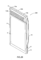
- Figure 23 illustrates the mobile electronic device 300 having four sections, the first auxiliary section 1, the main screen section 2, the second auxiliary section 5, and the back section 6.
- the first auxiliary section 1 includes the speaker 110.
- the speaker 110 functions to output or input or output and input audio to and from the device.
- the first auxiliary section 1 is connected at one end to the main screen section 2 and at an opposite end to the back section 6.
- Figure 23 illustrates, for example, hinges 10a-10c and the pin that connect the first auxiliary section 1 to the back section 6.
- the hinges may be rigid or flexible and may be made of metal, plastic, rubber, or other suitable material, for example.
- the first auxiliary section 1 may also be connected to the main screen section 2 and the back section 6 by way of other suitable connecting mechanisms.
- the first auxiliary section 1 may be connected to the main screen section 2 and the back section 6 by way of flexible material, such as rubber, which bends as the sections move.
- the flexible material may be formed with a bend that flattens as the sections move.
- the second auxiliary section 5 includes the keyboard 7 ( Figure 28 ).
- the keyboard 7, in one embodiment, may be a tactile keyboard.
- the second auxiliary section 5 could also include an additional display screen or touch screen that may or may not function as the keyboard.
- the second auxiliary section 5 could include, in place of or in addition to the keyboard or display screen, a touchless input device implemented via image sensors or other light or movement sensors.
- the second auxiliary section 5 is connected at one end to the main screen section 2 and at an opposite end to the back section 6 by way of, for example, a hinge similar to hinges 10a-10c and the pin ( Figure 24 ).
- the second auxiliary section 5 may also be connected to the main screen section 2 and the back section 6 by way of other suitable connecting mechanisms such as the mechanisms described above with respect to the first auxiliary section 1.
- the microprocessor is used to implement functions executed on the mobile electronic device 300 and to implement the display and execution of the operating system of the mobile electronic device 300 on the display screen 4.
- the memory is used to store programs and functions that are executed by the microprocessor.
- the back section 6 may be of differing thickness, such that one or more portions of the back section 6 is a first thickness and one or more portions of the back section 6 is a second thickness, wherein the first thickness is greater than the second thickness.
- variations in thickness may render the device 300 more comfortable during use, when the device is gripped by a user's hand(s). Further, such variations in thickness may provide a gripping surface for manipulating the device between the open and closed positions.
- the main screen section 2 includes the display screen 4.
- the display screen 4 may be a touch screen or other suitable device that displays information and receives input from a user.
- Figure 24 illustrates a front facing view of the mobile electronic device 300. From the front facing view only the first auxiliary section 1 and the main screen section 2 are shown.
- the first auxiliary section 1 includes the speaker/receiver 104, the opening 105, and the camera 106.
- FIG. 24 Also illustrated in Figure 24 are the hinges 10a-10c that connect the first auxiliary section 1 to the back section 6. Also illustrated in Figure 13 are the hinges 11a-11c that connect the main screen section 2 to the back section 6.
- FIG 25 illustrates a sectional view along line A-A shown in Figure 24 .
- each of the first auxiliary section 1, the main screen section 2, the second auxiliary section 5, and the back section 6 are shown.
- hinges 10a-c connecting the first auxiliary section 1 to the back section 6 and pin 14, which is disposed there-through.
- Hinges 13a-c with pin 17 there-through connect the first auxiliary section 1 to the main screen section 2.
- Hinges 12a-c and pin 16 there-through connect the back section 6 to the second auxiliary section 5 having the keyboard 7 thereon.
- Hinges 11a-c and pin 15 there-through connect the second auxiliary section 5 to the main screen section 2.
- a recess 20 is defined in a back side of the main screen section 2 (on the side that is opposite of the display screen 4).
- a recess 21 is defined in a back side of the back section 6 (on the side that is closest to the display screen 4).
- hinges 12a-c are resting in recess 22.
- the recess 22 provides space for hinges 12a-c and is defined in the back side of main screen section 2.
- Hinges 13a-c are resting in recess 19, which provides space for hinges 13a-c and is defined in the back side of back section 6.
- the recesses 19-22 enable a front face or first side of the device 300, including the main screen section 2 and either the first auxiliary section 1 or the second auxiliary section 5, to be positioned flat against a back face or second side of the device 300, including the back section 6 and either the first auxiliary section 1 or the second auxiliary section 5.
- Figure 26 illustrates a view of the mobile electronic device 300 in an open position as the device 300 transitions to the second state.
- the mobile electronic device 300 In the open position, the mobile electronic device 300 is in the process of switching from a first state to a second state.
- This switching is an example of the flipping mechanism.
- the first state is a state in which the first auxiliary section 1 and the main screen section 2 are on the first side of the device 300, and the back section 6 and the second auxiliary section 5 are on the second side of the device 300.
- the first and second sides are on opposite sides of the mobile electronic device 300.
- the second state is a state in which the second auxiliary section 5 and the main screen section 2 are on the first side of the device 300, and the back section 6 and the first auxiliary section 1 are on the second side of the device 300.
- the device 300 In the closed position, the device 300 has the same size footprint (length and width shown in Figure 24 ) in the first state and in the second state. As previously described, maintaining the same footprint in both the open and closed positions enables the device size to remain the same while providing large display/input areas, and prevents the device 300 from becoming too unwieldy.
- the keyboard or input device 7, respectively may be disabled.
- the keyboard 7 may be fully or partially enabled for input.
- a touch screen keyboard may be displayed on the display screen 4.
- the speaker 110 is still enabled for input/output of audio to/from the device 300.
- the clasping mechanism 30/31 can be implemented using a magnet 30 or 31 and a metal plate 30 or 31. Alternatively, the clasping mechanism can be implemented using two magnets 30 and 31. The mechanism can also be implemented with three magnets, with two of the magnets being positioned on either the main screen section 2 or the back section 6. Alternatively, the clasping mechanism 30/31 can be implemented with two metal sections and one magnet or two magnets and one metal section, where the two metal sections or two magnets are positioned on either the main screen section 2 or the back section 6.
- the clasping mechanism 30/31 can also be implemented with a mechanical clasp having a hook or clasp made of metal or plastic.
- the clasping mechanism 30/31 can also be implemented with a pin or a pin having a ball on the end.
- the clasping mechanism 30/31 can be released by force of the user or by a mechanical release.
- the user when the device 300 is in the closed position, the user is able release the clasping mechanism 30/31 by pulling the main screen section 2 apart from the back section 6.
- the user when the device 300 is in the closed position, the user is able release the clasping mechanism 30/31 by activating a mechanical release, such as a button, which will disengage the clasping mechanism 30/31.
- a mechanical release such as a button
- Figure 27 illustrates another view of the mobile electronic device 300 in the open position as the device 300 continues to transition to the second state.
- the mobile electronic device 300 may rest on its side to maintain an upright position for viewing purposes.
- the keyboard 7 may be disabled or may be enabled.
- the power or input connectors for the mobile electronic device 300 may be on a side 40 of the device, on a bottom 41 of the main screen section 2 or a bottom 42 of the back section 6.
- Figure 28 illustrates another view of the mobile electronic device 300.
- the display screen 4 and the keyboard 7 are presented to the user.
- the main screen section 2 and the second auxiliary section 5 are on the first side corresponding to the second state in the closed position.
- Figure 29 illustrates a front view of the mobile electronic device 300 in the second state and in the closed position.
- the hinges 13a-13c there is illustrated the hinges 13a-13c, the main screen section 2 having therein the display screen 4, and the second auxiliary section 5 having therein the keyboard 7.
- the hinges 12a-12c which connect the second auxiliary section 5 to the back section 6.
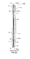
- Figure 30 illustrates a sectional view along line A-A found in Figure 29 .
- first auxiliary section 1 the main screen section 2, the second auxiliary section 5, and the back section 6 are shown.
- hinges 13a-c with pin 17 there-through connecting the first auxiliary section 1 to the main screen section 2.
- Hinges 10a-c and pin 14 which is disposed there-through, connect the first auxiliary section 1 to the back section 6.
- Hinges 12a-c and pin 16 there-through connect the back section 6 to the second auxiliary section 5 having the keyboard 7 thereon.
- Hinges 11a-c and pin 15 there-through connect the second auxiliary section 5 to the main screen section 2.
- FIG 30 Also shown in Figure 30 are recesses 19, 20, 21, and 22, which provide space for hinges 10a-13c.
- recesses 20 and 21 are occupied by hinges 10a-c and 11a-c, respectively.
- Figure 31 illustrates a side view of the mobile electronic device 300 in the open position as the device 300 transitions to the closed position and back to the first state of the device 100.
- first auxiliary section 1 the main screen section 2, the second auxiliary section 5, and the back section 6 are shown.
- hinges 10a-c, 11a-c, 12a-c, and 13a-c are also illustrated.
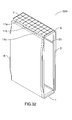
- Figure 32 illustrates another view of the mobile electronic device 300 in the open position as the device 300 continues to transition back to the first state.
- each of the first auxiliary section 1, the main screen section 2, the second auxiliary section 5, and the back section 6 are shown. Also shown is the keyboard 7 on the second auxiliary section 5 and the recess 21, which provides a space for hinges 11a-11c.
- Figure 33 illustrates an exploded view of the mobile electronic device 300.
- each of the first auxiliary section 1, the main screen section 2, the second auxiliary section 5, and the back section 6 are shown.
- each of the hinges 10a-c, 11a-c, 12a-c, and 13a-c, and pins 14-17 This view also illustrates that the hinges 10a-c, 11a-c and 12a-c may, in one embodiment, be composed of different pieces 50, 51, 53, 54, 55, and 57.
- the pieces 50, 51, 53, 54, 55, and 57 may be made of metal or plastic or some other suitable material.
- the hinges 10a-c can be composed of hinges attached or included in different pieces.
- Hinges 10a and 10c are connected to or included (i.e., integrally formed in) in piece 51.
- Hinge 10b is connected to or included in piece 50.
- pin 14 is inserted into hinges 10a-10c, pieces 50 and 51 are connected.
- Hinges 11a-11c can also be composed of hinges attached or included in different pieces. Hinges 11a and 11c are connected to or included in piece 57. Hinge 11b is connected to or included in piece 54. When pin 15 is inserted into hinges 11a-11c, pieces 57 and 54 are connected.
- Hinges 12a-12c can be composed of hinges attached or included in different pieces. Hinges 12a and 12c are connected to or included in piece 54. Hinge 12b is connected to or included in piece 53. When pin 16 is inserted into hinges 12a-12c, pieces 54 and 53 are connected.
- Hinges 13a-13c can be composed of hinges attached or included in different pieces. Hinges 13a and 13c are connected to or included in piece 50. Hinge 13b is connected to or included in piece 55. When pin 17 is inserted into hinges 13a-13c, pieces 55 and 50 are connected.
- pieces 50 and 54 include hinges from different hinge sets.
- Pieces 55, 56, and 57 are attached to the main screen section 2.
- Piece 54 is attached to second auxiliary section 5.
- Pieces 51, 52, and 53 are attached to back section 6.
- Piece 50 is attached to first auxiliary section 1.
- the pieces 50-57 can be connected to their respective sections 1, 2, 5, 6 by means of adhesives, welding, tab/groove connections, and the like.
- Recesses 19 and 21 are illustrated as spaces between pieces 51 and 52 and pieces 52 and 53, respectively.
- Recesses 20 and 22 are illustrated as spaces between pieces 55 and 56 and pieces 56 and 57, respectively.
- the recesses 19 and 21 and recesses 20 and 22 could respectively be defined in an integral piece of material, rather than being defined as spaces/gaps between the pieces.
- pieces 55-57 and 51-53 are each integral pieces (not shown) having recesses defined therein.
- pieces 52 and 56 may include the clasping mechanism 30/31 which retain the main screen section 2 and back section 6 to each other.
- the electrical connections between the first auxiliary section 1, the main screen section 2, the second auxiliary section 5, and the back section 6 are implemented with flexible wiring which, in one embodiment, passes over the hinge elements 10b, 11b, 12b, and 13b.
- the wiring can be protected by a cover layer which is also included on elements 10a-13a and elements 10c-13c.
- the described embodiments have numerous advantages. For example, as a result of the above described configuration it is possible to maintain the same footprint in both the open and closed positions which enables the device size to remain the same while providing large display/input areas, and prevents the device from becoming too unwieldy.
- the device is balanced when the keyboard is on the front face such that the device does not feel top-heavy to the user during typing on the keyboard.
- the device has the advantage of being modular such that, depending on the user's need, the device can include different modules (such as a keyboard, an additional display element, a camera or a input/output device) on the front face of the device.
- modules such as a keyboard, an additional display element, a camera or a input/output device
Landscapes
- Engineering & Computer Science (AREA)
- Signal Processing (AREA)
- Telephone Set Structure (AREA)
Abstract
A mobile electronic device including a first auxiliary section, a main screen section having a display screen, a second auxiliary section having a user input device, and a back section having a microprocessor and a battery. In a first state, the mobile electronic device includes the first auxiliary section and the main screen section on a first side of the device, and the second auxiliary section and the back section on a second side of the device, the first side and the second side being disposed on opposite sides of the mobile electronic device. In a second state, the mobile electronic device includes the second auxiliary section and the main screen section on the first side, and the first auxiliary section and the back section on the second side.
Description
- The present embodiments relate to a mobile electronic device achieving a larger display ratio as compared with the size of a device using a flipping mechanism.
- Conventional handheld devices concealed the keypad of the handheld device using a sliding mechanism by which the keypad would slide in and out of the body of the device. Such devices increased the size of the device when the keypad was in the "out" position. In addition, when the keypad is in the out position, the overall balance of the device is changed, resulting in the device feeling top-heavy to the user during typing on the keypad.
- A more complete appreciation of the disclosure and many of the attendant advantages thereof will be readily obtained as the same becomes better understood by reference to the following detailed description when considered in connection with the accompanying drawings, wherein:
-
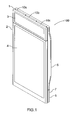
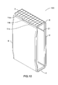
Figure 1 illustrates a view of a mobile electronic device in a closed configuration according to the first embodiment; -
Figure 2 illustrates a front view of the mobile electronic device in a closed configuration according to the first embodiment; -
Figure 3 illustrates a sectional view of the mobile electronic device in a closed configuration according to the first embodiment; -
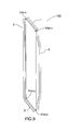
Figure 4 illustrates a side view of the mobile electronic device in an open configuration according to the first embodiment; -
Figure 5 illustrates another view of the mobile electronic device in an open configuration according to the first embodiment; -
Figure 6 illustrates another view of the mobile electronic device in a closed configuration and in a second state according to the first embodiment; -
Figure 7 illustrates a front view of the mobile electronic device in a closed configuration and in the second state according to the first embodiment; -
Figure 8 illustrates a sectional view of the mobile electronic device in a closed configuration and in the second state according to the first embodiment; -
Figure 9 illustrates another side view of the mobile electronic device in an open configuration according to the first embodiment; -
Figure 10 illustrates another view of the mobile electronic device in an open configuration according to the first embodiment; -
Figure 11 illustrates an exploded view of the mobile electronic device according to the first embodiment; -
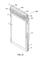
Figure 12 illustrates a view of a mobile electronic device in a closed configuration according to a second embodiment; -
Figure 13 illustrates a front view of the mobile electronic device in the closed configuration according to the second embodiment; -
Figure 14 illustrates a sectional view of the mobile electronic device in the closed configuration according to the second embodiment; -
Figure 15 illustrates a side view of the mobile electronic device in an open configuration according to the second embodiment; -
Figure 16 illustrates another view of the mobile electronic device in an open configuration according to the second embodiment; -
Figure 17 illustrates another view of the mobile electronic device in a closed configuration and in a second state according to the second embodiment; -
Figure 18 illustrates a front view of the mobile electronic device in the closed configuration and in the second state according to the second embodiment; -
Figure 19 illustrates a sectional view of the mobile electronic device in the closed configuration and in the second state according to the second embodiment; -
Figure 20 illustrates another side view of the mobile electronic device in an open configuration according to the second embodiment; -
Figure 21 illustrates another view of the mobile electronic device in an open configuration according to the second embodiment; -
Figure 22 illustrates an exploded view of the mobile electronic device according to the second embodiment; -
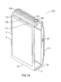
Figure 23 illustrates a view of a mobile electronic device in a closed configuration according to a third embodiment; -
Figure 24 illustrates a front view of the mobile electronic device in the closed configuration according to the third embodiment; -
Figure 25 illustrates a sectional view of the mobile electronic device in the closed configuration according to the third embodiment; -
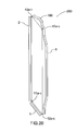
Figure 26 illustrates a side view of the mobile electronic device in an open configuration according to the third embodiment; -
Figure 27 illustrates another view of the mobile electronic device in an open configuration according to the third embodiment; -
Figure 28 illustrates another view of the mobile electronic device in a closed configuration and in a second state according to the third embodiment; -
Figure 29 illustrates a front view of the mobile electronic device in the closed configuration and in the second state according to the third embodiment; -
Figure 30 illustrates a sectional view of the mobile electronic device in the closed configuration and in the second state according to the third embodiment; -
Figure 31 illustrates another side view of the mobile electronic device in an open configuration according to the third embodiment; -
Figure 32 illustrates another view of the mobile electronic device in an open configuration according to the third embodiment; and -
Figure 33 illustrates an exploded view of the mobile electronic device according to the third embodiment. - Referring now to the drawings wherein like reference numbers designate identical or corresponding parts throughout the several views and more particularly to
Figure 1 thereof, there is illustrated a mobileelectronic device 100 having four sections, a firstauxiliary section 1, amain screen section 2, a secondauxiliary section 5, and aback section 6. - The first
auxiliary section 1 includes adisplay screen 3. Thedisplay screen 3 may include a touch screen or other similar input device. The firstauxiliary section 1 is connected at one end to themain screen section 2 and at an opposite end to theback section 6.Figure 1 illustrates, for example, hinges 10a-10c and a pin that connect the firstauxiliary section 1 to theback section 6. The hinges may be rigid or flexible and may be made of metal, plastic, rubber, or other suitable material, for example. The firstauxiliary section 1 may also be connected to themain screen section 2 and theback section 6 by way of other suitable connecting methods. For instance, the firstauxiliary section 1 may be connected to themain screen section 2 and theback section 6 by way of flexible material, such as rubber, which bends as the sections move. In one embodiment, the flexible material may be formed with a bend that flattens as the sections move. - The second
auxiliary section 5 includes a keyboard 7 (Figure 6 ). Thekeyboard 7, in one embodiment, may be a tactile keyboard. The secondauxiliary section 5 could also include an additional display screen or touch screen that may or may not function as a keyboard. In addition, the secondauxiliary section 5 could include, in place of or in addition to the keyboard or display screen, a touchless input device implemented via image sensors or other light or movement sensors. The secondauxiliary section 5 is connected at one end to themain screen section 2 and at an opposite end to theback section 6 by way of, for example, hinges similar tohinges 10a-10c and a pin (Figure 2 ). The secondauxiliary section 5 may also be connected to themain screen section 2 and theback section 6 by way of other suitable connecting mechanisms, such as the mechanisms described above with respect to the firstauxiliary section 1. - The
back section 6, in one embodiment, includes a battery in addition to circuits associated with operation of the mobileelectronic device 100, such as a microprocessor and memory. The microprocessor is used to implement functions executed on the mobileelectronic device 100 and to implement the display and execution of the operating system of the mobileelectronic device 100 on thedisplay screen 3 and adisplay screen 4. The memory is used to store programs and functions that are executed by the microprocessor. - The
back section 6 may be of differing thickness such that one or more portions of theback section 6 is a first thickness, and one or more portions of theback section 6 is a second thickness, wherein the first thickness is greater than the second thickness. Such variations in thickness may render thedevice 100 more comfortable during use, when thedevice 100 is gripped by a user's hand(s). Further, such variations in thickness may provide a gripping surface for manipulating thedevice 100 between the open and closed positions. - In one embodiment, the
main screen section 2 includes thedisplay screen 4. Thedisplay screen 4 may be a touch screen or other suitable device that displays information and receives input from a user. - The
display screen 4 may display information independent of, or in concert with, the information displayed ondisplay screen 3. For example, thedisplay screen 3 may be an extension of thedisplay screen 4 such that the screen appears to be larger in size. Alternatively, thedisplay screen 3 may display information in concert with thedisplay screen 4, but without making the screen appear to be a larger size (e.g. a window open on thedisplay screen 4 would not extend into thedisplay screen 3, while a window would extend into thedisplay screen 3 in the alternate embodiment). In addition, in one embodiment, there is a border around each of thedisplay screen 4 and thedisplay screen 3. Alternatively, in another embodiment, thedisplay screen 4 and thedisplay screen 3 are substantially flush and may include or may not include a protective layer that is disposed between thedisplay screen 3 and thedisplay screen 4. - The
display screen 3 may also display content and receive input from a user independent from, or related to, the content displayed on thedisplay screen 4. For example, thedisplay screen 3 may display advertisements, location-based information, launch icons, or shortcut icons. Thedisplay screen 3 could include tabs allowing the user to switch between windows on thedisplay screen 4. -
Figure 2 illustrates a front facing view of the mobileelectronic device 100. From the front facing view only the firstauxiliary section 1 and themain screen section 2 are shown. Illustrated inFigure 2 are thehinges 10a-10c that connect the firstauxiliary section 1 to theback section 6. Also illustrated inFigure 2 arehinges 11a-11c that connect themain screen section 2 to theback section 6. -
Figure 3 illustrates a sectional view along the line A-A shown inFigure 2 . InFigure 3 , each of the firstauxiliary section 1, themain screen section 2, the secondauxiliary section 5, and theback section 6 are shown. Also shown arehinges 10a-c connecting the firstauxiliary section 1 to theback section 6 andpin 14, which is disposed there-through.Hinges 13a-c withpin 17 there-through connect the firstauxiliary section 1 to themain screen section 2.Hinges 12a-c and pin 16 there-through connect theback section 6 to the secondauxiliary section 5 having thekeyboard 7 thereon.Hinges 11a-c and pin 15 there-through connect the secondauxiliary section 5 to themain screen section 2. - To provide space for
hinges 10a-c a recess 20 is defined in a back side of the main screen section 2 (on the side that is opposite of the display screen 4). To provide space forhinges 11a-c, arecess 21 is defined in a back side of the back section 6 (on the side that is closest to the display screen 4). - In the state shown in
Figure 3 , hinges 12a-c are resting inrecess 22. Therecess 22 provides space forhinges 12a-c and is defined in the back side ofmain screen section 2.Hinges 13a-c are resting inrecess 19, which provides space forhinges 13a-c and is defined in the back side ofback section 6. - The recesses 19-22 enable a front face or first side of the
device 100, including themain screen section 2 and either the firstauxiliary section 1 or the secondauxiliary section 5, to be positioned flat against a back face or second side of thedevice 100, including theback section 6 and either the firstauxiliary section 1 or the secondauxiliary section 5. -
Figure 4 illustrates a view of the mobileelectronic device 100 in an open position as thedevice 100 transitions to the second state. In the open position, the mobileelectronic device 100 is in the process of switching from a first state to a second state. This switching is an example of the flipping mechanism. The first state is a state in which the firstauxiliary section 1 and themain screen section 2 are on the first side of thedevice 100, and theback section 6 and the secondauxiliary section 5 are on the second side of thedevice 100. The first and second sides are on opposite sides of the mobileelectronic device 100. The second state is a state in which the secondauxiliary section 5 and themain screen section 2 are on the first side of thedevice 100, and theback section 6 and the firstauxiliary section 1 are on the second side of thedevice 100. - In the closed position, the
device 100 has the same size footprint (length and width shown inFigure 2 ) in the first state and in the second state. Maintaining the same footprint in both the open and closed positions enables the device size to remain the same while providing large display/input areas, and prevents thedevice 100 from becoming too unwieldy. - When the first
auxiliary section 1 or the secondauxiliary section 5 is on the second side, thedisplay screen 3 or the keyboard orinput device 7, respectively, may be disabled. Alternatively, thedisplay screen 3 or thekeyboard 7 may be fully or partially enabled for input. In addition, thedisplay screen 3 may be disabled for input, but enabled for display only. When thekeyboard 7 is on the second side, a touch screen keyboard may be displayed on thedisplay screen 4 or on thedisplay screen 3. When the touch screen keyboard is displayed on thedisplay screen 3 the image on thedisplay screen 4 may be rotated. Thedisplay screen 4 and thedisplay screen 3 may also be rotated independently or as a single unit in response to rotation of thedevice 100 by a user. - To keep the first side of the
device 100 attached to the second side of thedevice 100 when in the closed position, there is utilized aclasping mechanism 30/31. The clasping mechanism can be implemented using amagnet metal plate magnets main screen section 2 or theback section 6. Alternatively, theclasping mechanism 30/31 can be implemented with two metal sections and one magnet or two magnets and one metal section, where the two metal sections or two magnets are positioned on either themain screen section 2 or theback section 6. - The
clasping mechanism 30/31 can also be implemented with a mechanical clasp having a hook or clasp made of metal or plastic. Theclasping mechanism 30/31 can also be implemented with a pin or a pin having a ball on the end. - The
clasping mechanism 30/31 can be released by force of the user or by a mechanical release. For example, when thedevice 100 is in the closed position, the user is able release theclasping mechanism 30/31 by pulling themain screen section 2 apart from theback section 6. Alternatively, when thedevice 100 is in the closed position, the user is able release theclasping mechanism 30/31 by activating a mechanical release, such as a button, which will disengage theclasping mechanism 30/31. Once theclasping mechanism 30/31 is disengaged, thedevice 100 is in the open position. The user may return thedevice 100 to the closed position by bringing themain screen section 2 and theback section 6 together. The process of returning thedevice 100 to the closed position also allows the user to select between the first and second states of thedevice 100. - In an alternate embodiment, the first
auxiliary section 1 may split into two portions allowing thedisplay screen 3 to partially separate from a core portion (e.g. element 50 inFigure 11 discussed below) of the firstauxiliary section 1 and extend above themain screen section 2, such that, when in the second state, the first side would include thedisplay screen 3, thedisplay screen 4, and the keyboard 7 (not shown). Thus, thedisplay screen 3 is able to flex/separate such that thedisplay screen 3 is on the same side as themain display screen 4 and thekeyboard 7, when thedevice 100 is in the second state (since in the first state, the keyboard is on the second/back side of the device 100). Thedisplay screen 3 could be connected to the core portion of the firstauxiliary section 1 by a hinge, etc. Thedisplay screen 3 could be connected to the core portion of the firstauxiliary section 1 by a clasp or a magnetic holding device. A similar alternate embodiment could be implemented for thekeyboard 7 and the secondauxiliary section 5. - In an additional alternative embodiment, the
main screen section 2 and theback section 6 could be directly connected to each other, without the firstauxiliary section 1 connected therebetween. In this embodiment themain screen section 2 and theback section 6 form a top portion. Moreover, in this embodiment, the firstauxiliary section 1 and secondauxiliary section 5 could be disposed back to back such that the firstauxiliary section 1 and the secondauxiliary section 5 are directly connected without theback section 6 therebetween. The firstauxiliary section 1 and the secondauxiliary section 5 would form a bottom portion. The bottom portion could rotate with respect to the top portion so that thekeyboard 7 is below thedisplay screen 4 in one state, and thedisplay screen 3 is below thedisplay screen 4 in another state. -
Figure 5 illustrates another view of the mobileelectronic device 100 in the open position as thedevice 100 continues to transition to the second state. - In the open position, the mobile
electronic device 100 may rest on its side to maintain an upright position for viewing purposes. In the open position, thedisplay screen 3 or thekeyboard 7 may be disabled or may be enabled. - The power or input connectors for the mobile
electronic device 100 may be on aside 40 of the device, on a bottom 41 of themain screen section 2 or a bottom 42 of theback section 6. -
Figure 6 illustrates another view of the mobileelectronic device 100. In this view, thedisplay screen 4 and thekeyboard 7 are presented to the user. In this view, themain screen section 2 and the secondauxiliary section 5 are on the first side of thedevice 100, corresponding to the second state in the closed position. - In this second state, the
hinges 13a-13c connecting themain screen section 2 to the firstauxiliary section 1 are shown. Also shown is thekeyboard 7 of the secondauxiliary section 5 and theback section 6. -
Figure 7 illustrates a front view of the mobileelectronic device 100 in the second state and in the closed position. In this view, thehinges 13a-13c, themain screen section 2 having therein thedisplay screen 4, and the secondauxiliary section 5 having therein thekeyboard 7 are illustrated. Also illustrated inFigure 7 are thehinges 12a-12c, which connect the secondauxiliary section 5 to theback section 6. -
Figure 8 illustrates a sectional view along line A-A shown inFigure 7 . InFigure 8 , each of the firstauxiliary section 1, themain screen section 2, the secondauxiliary section 5 and theback section 6 are shown. Also shown arehinges 13a-c withpin 17 there-through connecting the firstauxiliary section 1 to themain screen section 2.Hinges 10a-c andpin 14, which is disposed there-through, connect the firstauxiliary section 1 to theback section 6.Hinges 12a-c and pin 16 there-through connect theback section 6 to the secondauxiliary section 5 having thekeyboard 7 thereon.Hinges 11a-c and pin 15 there-through connect the secondauxiliary section 5 to themain screen section 2. - Also shown in
Figure 8 arerecesses hinges 10a-13c. In the view shown inFigure 8 , recesses 20 and 21 are occupied byhinges 10a-c and 11a-c, respectively. -
Figure 9 illustrates a side view of the mobileelectronic device 100 in the open position as thedevice 100 transitions to the closed position and back to the first state of thedevice 100. In this view, each of the firstauxiliary section 1, themain screen section 2, the secondauxiliary section 5, and theback section 6 are shown. Also illustrated are thehinges 10a-c, 11a-c, 12a-c, and 13a-c. -
Figure 10 illustrates another view of the mobileelectronic device 100 in the open position as thedevice 100 continues to transition back to the first state. In this view, each of the firstauxiliary section 1, themain screen section 2, the secondauxiliary section 5, and theback section 6 are shown. Also shown is thekeyboard 7 on the secondauxiliary section 5 and therecess 21, which provides a space forhinges 11a-11c. -
Figure 11 illustrates an exploded view of the mobileelectronic device 100. - In this view, each of the first
auxiliary section 1, themain screen section 2, the secondauxiliary section 5, and theback section 6 are shown. - Also illustrated are each of the
hinges 10a-c, 11a-c, 12a-c, and 13a-c and pins 14-17. This view also illustrates that thehinges 10a-c, 11a-c, and 12a-c may, in one embodiment, be composed ofdifferent pieces pieces - As is illustrated in
Figure 11 , thehinges 10a-10c can be composed of hinges attached or included in different pieces.Hinges piece 51.Hinge 10b is connected to or included inpiece 50. Whenpin 14 is inserted intohinges 10a-10c,pieces -
Hinges 11a-11c can also be composed of hinges attached or included in different pieces.Hinges piece 57.Hinge 11b is connected to or included inpiece 54. Whenpin 15 is inserted intohinges 11a-11c,pieces -
Hinges 12a-12c can be composed of hinges attached or included in different pieces.Hinges piece 54.Hinge 12b is connected to or included inpiece 53. Whenpin 16 is inserted intohinges 12a-12c,pieces -
Hinges 13a-13c can be composed of hinges attached or included in different pieces.Hinges piece 50.Hinge 13b is connected to or included inpiece 55. Whenpin 17 is inserted intohinges 13a-13c,pieces - Thus, as is illustrated in
Figure 11 ,pieces -
Pieces main screen section 2.Piece 54 is attached to secondauxiliary section 5.Pieces section 6.Piece 50 is attached to firstauxiliary section 1. Although other manners of attachment are possible, the pieces 50-57 can be connected to theirrespective sections - Also illustrated in
Figure 11 arerecesses Recesses pieces pieces Recesses pieces pieces - In an alternative embodiment, the
recesses - In addition, in one embodiment,
pieces clasping mechanism 30/31 which retain themain screen section 2 andback section 6 to each other. - The electrical connections between the first
auxiliary section 1, themain screen section 2, the secondauxiliary section 5, and theback section 6 are implemented with flexible wiring which, in one embodiment, passes over thehinge elements elements 10a-13a andelements 10c-13c. - The second embodiment will now be described with reference to the above-described first embodiment. The reference numerals that are the same as those in the first embodiment will remain consistent with the first embodiment unless there is a special necessity. In the second embodiment, the first
auxiliary section 1 of a mobileelectronic device 200 includes a speaker/receiver 104, acamera 106, and anopening 105, which can include an LED which functions as a flash. Alternatively, opening 105 can include a proximity or light sensor, or the LED can be included in addition to the sensor. -
Figure 12 illustrates the mobileelectronic device 200 having four sections, the firstauxiliary section 1, themain screen section 2, the secondauxiliary section 5, and theback section 6. - The first
auxiliary section 1 includes the speaker/receiver 104, thecamera 106, and theopening 105. The speaker/receiver 104 functions to output and input audio to and from the device. Thecamera 106 may be a high quality camera which functions for video conferencing and for capturing still photographs or videos. Theopening 105 may include an LED flash, a proximity sensor, a light sensor, or some combination of each. - The first
auxiliary section 1 is connected at one end to themain screen section 2 and at an opposite end to theback section 6.Figure 12 illustrates, for example, hinges 10a-10c and a corresponding pin that connect the firstauxiliary section 1 to theback section 6. The hinges may be rigid or flexible and may be made of metal, plastic, rubber, or other suitable material, for example. The firstauxiliary section 1 may also be connected to themain screen section 2 and theback section 6 by way of other suitable connecting methods. For instance, the firstauxiliary section 1 may be connected to themain screen section 2 and theback section 6 by way of flexible material such as rubber that bends as the sections move. In one embodiment, the flexible material may be formed with a bend that flattens as the sections move. - The second
auxiliary section 5 includes the keyboard 7 (Figure 17 ). Thekeyboard 7, in one embodiment, may be a tactile keyboard. The secondauxiliary section 5 could also include an additional display screen or touch screen that may or may not function as the keyboard. In addition, the secondauxiliary section 5 could include, in place of or in addition to the keyboard or display screen, a touchless input device implemented via image sensors or other light or movement sensors. The secondauxiliary section 5 is connected at one end to themain screen section 2 and at an opposite end to theback section 6 by way of, for example, a hinge similar tohinges 10a-10c and the pin (Figure 13 ). The secondauxiliary section 5 may also be connected to themain screen section 2 and theback section 6 by way of other suitable connecting mechanisms, such as the mechanisms described above with respect to the firstauxiliary section 1. - The
back section 6, in one embodiment, includes the battery in addition to circuits associated with operation of the mobileelectronic device 200, such as a microprocessor and memory. The microprocessor is used to implement functions executed on the mobileelectronic device 200 and to implement the display and execution of the operating system of the mobileelectronic device 200 on thedisplay screen 4. The memory is used to store programs and functions that are executed by the microprocessor. - The
back section 6 may be of differing thickness, such that one or more portions of theback section 6 is a first thickness and one or more portions of theback section 6 is a second thickness, wherein the first thickness is greater than the second thickness. As previously indicated with respect todevice 100, such variations in thickness may render thedevice 200 more comfortable during use, when the device is gripped by a user's hand(s). Further, such variations in thickness may provide a gripping surface for manipulating thedevice 200 between the open and closed positions. - In one embodiment, the
main screen section 2 includes thedisplay screen 4. Thedisplay screen 4 may be a touch screen or other suitable device that displays information and receives input from a user. -
Figure 13 illustrates a front facing view of the mobileelectronic device 200. From the front facing view only the firstauxiliary section 1 and themain screen section 2 are shown. The firstauxiliary section 1 includes the speaker/receiver 104, theopening 105, and thecamera 106. - Also illustrated in
Figure 13 are thehinges 10a-10c that connect the firstauxiliary section 1 to theback section 6. Also illustrated inFigure 13 are thehinges 11a-11c that connect themain screen section 2 to theback section 6. -
Figure 14 illustrates a sectional view along line A-A shown inFigure 13 . InFigure 14 , each of the firstauxiliary section 1, themain screen section 2, the secondauxiliary section 5, and theback section 6 are shown. Also shown arehinges 10a-c connecting the firstauxiliary section 1 to theback section 6 and pin 14 which is disposed there-through.Hinges 13a-c withpin 17 there-through connect the firstauxiliary section 1 to themain screen section 2.Hinges 12a-c and pin 16 there-through connect theback section 6 to the secondauxiliary section 5 having thekeyboard 7 thereon.Hinges 11a-c and pin 15 there-through connect the secondauxiliary section 5 to themain screen section 2. - To provide space for
hinges 10a-c a recess 20 is defined in a back side of the main screen section 2 (on the side that is opposite of the display screen 4). To provide space forhinges 11a-c, arecess 21 is defined in a back side of the back section 6 (on the side that is closest to the display screen 4). - In the state shown in
Figure 14 , hinges 12a-c are resting inrecess 22. Therecess 22 provides space forhinges 12a-c and is defined in the back side ofmain screen section 2.Hinges 13a-c are resting inrecess 19, which provides space forhinges 13a-c and is defined in the back side ofback section 6. - The recesses 19-22 enable a front face or first side of the
device 200, including themain screen section 2 and either the firstauxiliary section 1 or the secondauxiliary section 5, to be positioned flat against a back face or second side of thedevice 200, including theback section 6 and either the firstauxiliary section 1 or the secondauxiliary section 5. -
Figure 15 illustrates a view of the mobileelectronic device 200 in an open position as thedevice 200 transitions to a second state. In the open position, the mobileelectronic device 200 is in the process of switching from a first state to the second state. This switching is an example of the flipping mechanism. The first state is a state in which the firstauxiliary section 1 and themain screen section 2 are on the first side of thedevice 200, and theback section 6 and the secondauxiliary section 5 are on the second side of thedevice 200. The first and second sides are on opposite sides of the mobileelectronic device 200. The second state is a state in which the secondauxiliary section 5 and themain screen section 2 are on the first side of thedevice 200, and theback section 6 and the firstauxiliary section 1 are on the second side of thedevice 200. - In the closed position, the
device 200 has the same size footprint (length and width shown inFigure 13 ) in the first state and in the second state. As previously described, maintaining the same footprint in both the open and closed positions enables the device size to remain the same while providing large display/input areas, and prevents thedevice 200 from becoming too unwieldy. - When the second
auxiliary section 5 is on the second side, the keyboard orinput device 7, respectively, may be disabled. Alternatively, thekeyboard 7 may be fully or partially enabled for input. When thekeyboard 7 is on the second side, a touch screen keyboard may be displayed on thedisplay screen 4. - When the second
auxiliary section 1 is on the second side, thecamera 106 is still enabled for video or still picture capture. - To keep the first side of the
device 200 attached to the second side of thedevice 200 when in the closed position, there is utilized aclasping mechanism 30/31. The clasping mechanism can be implemented using amagnet metal plate magnets main screen section 2 or theback section 6. Alternatively, theclasping mechanism 30/31 can be implemented with two metal sections and one magnet or two magnets and one metal section, where the two metal sections or two magnets are positioned on either themain screen section 2 or theback section 6. - The
clasping mechanism 30/31 can also be implemented with a mechanical clasp having a hook or clasp made of metal or plastic. Theclasping mechanism 30/31 can also be implemented with a pin or a pin having a ball on the end. - The
clasping mechanism 30/31 can be released by force of the user or by a mechanical release. For example, when thedevice 200 is in the closed position, the user is able release theclasping mechanism 30/31 by pulling themain screen section 2 apart from theback section 6. Alternatively, when thedevice 200 is in the closed position, the user is able release theclasping mechanism 30/31 by activating a mechanical release, such as a button, which will disengage theclasping mechanism 30/31. Once theclasping mechanism 30/31 is disengaged, thedevice 200 is in the open position. The user may return thedevice 200 to the closed position by bringing themain screen section 2 and theback section 6 together. The process of returning thedevice 200 to the closed position also allows the user to select between the first and second states of thedevice 200. -
Figure 16 illustrates another view of the mobileelectronic device 200 in the open position as thedevice 200 continues to transition to the second state. - In the open position, the mobile
electronic device 200 may rest on its side to maintain an upright position for viewing purposes. In the open position, thecamera 106 or thekeyboard 7 may be disabled or may be enabled. - The power or input connectors for the mobile
electronic device 200 may be on aside 40 of the device, on a bottom 41 of themain screen section 2 or a bottom 42 of theback section 6. -
Figure 17 illustrates another view of the mobileelectronic device 200. In this view, thedisplay screen 4 and thekeyboard 7 are presented to the user. In this view, themain screen section 2 and the secondauxiliary section 5 are on the first side of thedevice 200, corresponding to the second state in the closed position. - In this second state, the
hinges 13a-13c connecting themain screen section 2 to the firstauxiliary section 1 are shown. Also shown is thekeyboard 7 of the secondauxiliary section 5 and theback section 6. -
Figure 18 illustrates a front view of the mobileelectronic device 200 in the second state and in the closed position. In this view, there is illustrated thehinges 13a-13c, themain screen section 2 having therein thedisplay screen 4 and the secondauxiliary section 5 having therein thekeyboard 7. Also illustrated inFigure 18 are thehinges 12a-12c, which connect the secondauxiliary section 5 to theback section 6. -
Figure 19 illustrates a sectional view along line A-A shown inFigure 18 . InFigure 19 , each of the firstauxiliary section 1, themain screen section 2, the secondauxiliary section 5, and theback section 6 are shown. Also shown arehinges 13a-c withpin 17 there-through connecting the firstauxiliary section 1 to themain screen section 2.Hinges 10a-c andpin 14, which is disposed there-through, connect the firstauxiliary section 1 to theback section 6.Hinges 12a-c and pin 16 there-through connect theback section 6 to the secondauxiliary section 5 having thekeyboard 7 thereon.Hinges 11a-c and pin 15 there-through connect the secondauxiliary section 5 to themain screen section 2. - Also shown in
Figure 19 arerecesses hinges 10a-13c. In the view shown inFigure 19 , recesses 20 and 21 are occupied byhinges 10a-c and 11a-c, respectively. -
Figure 20 illustrates a side view of the mobileelectronic device 200 in the open position as thedevice 200 transitions to the closed position and back to the first state of thedevice 200. In this view, each of the firstauxiliary section 1, themain screen section 2, the secondauxiliary section 5, and theback section 6 are shown. Also illustrated are thehinges 10a-c, 11a-c, 12a-c, and 13a-c. -
Figure 21 illustrates another view of the mobileelectronic device 200 in the open position as thedevice 200 continues to transition back to the first state. In this view, each of the firstauxiliary section 1, themain screen section 2, the secondauxiliary section 5, and theback section 6 are shown. Also shown is thekeyboard 7 on the secondauxiliary section 5 and therecess 21, which provides a space forhinges 11a-11c. -
Figure 22 illustrates an exploded view of the mobileelectronic device 200. - In this view, each of the first
auxiliary section 1, themain screen section 2, the secondauxiliary section 5, and theback section 6 are shown. - Also illustrated are each of the
hinges 10a-c, 11a-c, 12a-c, and 13a-c and pins 14-17. This view also illustrates that thehinges 10a-c, 11a-c, and 12a-c may, in one embodiment, be composed ofdifferent pieces pieces - As is illustrated in
Figure 22 , thehinges 10a-10c can be composed of hinges attached or included (i.e., integral with) in different pieces.Hinges piece 51.Hinge 10b is connected to or included inpiece 50. Whenpin 14 is inserted intohinges 10a-10c,pieces -
Hinges 11a-11c can also be composed of hinges attached or included in different pieces.Hinges piece 57.Hinge 11b is connected to or included inpiece 54. Whenpin 15 is inserted intohinges 11a-11c,pieces -
Hinges 12a-12c can be composed of hinges attached or included in different pieces.Hinges piece 54.Hinge 12b is connected to or included inpiece 53. Whenpin 16 is inserted intohinges 12a-12c,pieces -
Hinges 13a-13c can be composed of hinges attached or included in different pieces.Hinges piece 50.Hinge 13b is connected to or included inpiece 55. Whenpin 17 is inserted intohinges 13a-13c,pieces - Thus, as is illustrated in
Figure 22 ,pieces -
Pieces main screen section 2.Piece 54 is attached to secondauxiliary section 5.Pieces section 6.Piece 50 is attached to firstauxiliary section 1. As previously discussed with respect todevice 100, although other manners of attachment are possible, the pieces 50-57 can be connected to theirrespective sections - Also illustrated in
Figure 22 arerecesses Recesses pieces pieces Recesses pieces pieces - In an alternative embodiment, the
recesses - In addition, in one embodiment,
pieces clasping mechanism 30/31 which retain themain screen section 2 andback section 6 to each other. - The electrical connections between the first
auxiliary section 1, themain screen section 2, the secondauxiliary section 5, and theback section 6 are implemented with flexible wiring which, in one embodiment, passes over thehinge elements elements 10a-13a andelements 10c-13c. - The third embodiment will now be described with reference to the above-described first and second embodiments. The reference numerals that are the same as those in the first and second embodiments will remain consistent with the first and second embodiments unless there is a special necessity. In the third embodiment, the first
auxiliary section 1 of a mobileelectronic device 300 includes aspeaker 110. Alternatively, thespeaker 110 can also include a speaker/receiver. -
Figure 23 illustrates the mobileelectronic device 300 having four sections, the firstauxiliary section 1, themain screen section 2, the secondauxiliary section 5, and theback section 6. - The first
auxiliary section 1 includes thespeaker 110. Thespeaker 110 functions to output or input or output and input audio to and from the device. - The first
auxiliary section 1 is connected at one end to themain screen section 2 and at an opposite end to theback section 6.Figure 23 illustrates, for example, hinges 10a-10c and the pin that connect the firstauxiliary section 1 to theback section 6. The hinges may be rigid or flexible and may be made of metal, plastic, rubber, or other suitable material, for example. The firstauxiliary section 1 may also be connected to themain screen section 2 and theback section 6 by way of other suitable connecting mechanisms. For instance, the firstauxiliary section 1 may be connected to themain screen section 2 and theback section 6 by way of flexible material, such as rubber, which bends as the sections move. In one embodiment, the flexible material may be formed with a bend that flattens as the sections move. - The second
auxiliary section 5 includes the keyboard 7 (Figure 28 ). Thekeyboard 7, in one embodiment, may be a tactile keyboard. The secondauxiliary section 5 could also include an additional display screen or touch screen that may or may not function as the keyboard. In addition, the secondauxiliary section 5 could include, in place of or in addition to the keyboard or display screen, a touchless input device implemented via image sensors or other light or movement sensors. The secondauxiliary section 5 is connected at one end to themain screen section 2 and at an opposite end to theback section 6 by way of, for example, a hinge similar tohinges 10a-10c and the pin (Figure 24 ). The secondauxiliary section 5 may also be connected to themain screen section 2 and theback section 6 by way of other suitable connecting mechanisms such as the mechanisms described above with respect to the firstauxiliary section 1. - The
back section 6, in one embodiment, includes the battery in addition to circuits associated with operation of the mobileelectronic device 300, such as a microprocessor and memory. The microprocessor is used to implement functions executed on the mobileelectronic device 300 and to implement the display and execution of the operating system of the mobileelectronic device 300 on thedisplay screen 4. The memory is used to store programs and functions that are executed by the microprocessor. - The
back section 6 may be of differing thickness, such that one or more portions of theback section 6 is a first thickness and one or more portions of theback section 6 is a second thickness, wherein the first thickness is greater than the second thickness. As previously discussed with respect todevices device 300 more comfortable during use, when the device is gripped by a user's hand(s). Further, such variations in thickness may provide a gripping surface for manipulating the device between the open and closed positions. - In one embodiment, the
main screen section 2 includes thedisplay screen 4. Thedisplay screen 4 may be a touch screen or other suitable device that displays information and receives input from a user. -
Figure 24 illustrates a front facing view of the mobileelectronic device 300. From the front facing view only the firstauxiliary section 1 and themain screen section 2 are shown. The firstauxiliary section 1 includes the speaker/receiver 104, theopening 105, and thecamera 106. - Also illustrated in
Figure 24 are thehinges 10a-10c that connect the firstauxiliary section 1 to theback section 6. Also illustrated inFigure 13 are thehinges 11a-11c that connect themain screen section 2 to theback section 6. -
Figure 25 illustrates a sectional view along line A-A shown inFigure 24 . InFigure 25 , each of the firstauxiliary section 1, themain screen section 2, the secondauxiliary section 5, and theback section 6 are shown. Also shown arehinges 10a-c connecting the firstauxiliary section 1 to theback section 6 andpin 14, which is disposed there-through.Hinges 13a-c withpin 17 there-through connect the firstauxiliary section 1 to themain screen section 2.Hinges 12a-c and pin 16 there-through connect theback section 6 to the secondauxiliary section 5 having thekeyboard 7 thereon.Hinges 11a-c and pin 15 there-through connect the secondauxiliary section 5 to themain screen section 2. - To provide space for
hinges 10a-c a recess 20 is defined in a back side of the main screen section 2 (on the side that is opposite of the display screen 4). To provide space forhinges 11a-c, arecess 21 is defined in a back side of the back section 6 (on the side that is closest to the display screen 4). - In the state shown in
Figure 25 , hinges 12a-c are resting inrecess 22. Therecess 22 provides space forhinges 12a-c and is defined in the back side ofmain screen section 2.Hinges 13a-c are resting inrecess 19, which provides space forhinges 13a-c and is defined in the back side ofback section 6. - The recesses 19-22 enable a front face or first side of the
device 300, including themain screen section 2 and either the firstauxiliary section 1 or the secondauxiliary section 5, to be positioned flat against a back face or second side of thedevice 300, including theback section 6 and either the firstauxiliary section 1 or the secondauxiliary section 5. -
Figure 26 illustrates a view of the mobileelectronic device 300 in an open position as thedevice 300 transitions to the second state. In the open position, the mobileelectronic device 300 is in the process of switching from a first state to a second state. This switching is an example of the flipping mechanism. The first state is a state in which the firstauxiliary section 1 and themain screen section 2 are on the first side of thedevice 300, and theback section 6 and the secondauxiliary section 5 are on the second side of thedevice 300. The first and second sides are on opposite sides of the mobileelectronic device 300. The second state is a state in which the secondauxiliary section 5 and themain screen section 2 are on the first side of thedevice 300, and theback section 6 and the firstauxiliary section 1 are on the second side of thedevice 300. - In the closed position, the
device 300 has the same size footprint (length and width shown inFigure 24 ) in the first state and in the second state. As previously described, maintaining the same footprint in both the open and closed positions enables the device size to remain the same while providing large display/input areas, and prevents thedevice 300 from becoming too unwieldy. - When the second
auxiliary section 5 is on the second side, the keyboard orinput device 7, respectively, may be disabled. Alternatively, thekeyboard 7 may be fully or partially enabled for input. When thekeyboard 7 is on the second side, a touch screen keyboard may be displayed on thedisplay screen 4. - When the second
auxiliary section 1 is on the second side, thespeaker 110 is still enabled for input/output of audio to/from thedevice 300. - To keep the first side of the
device 300 attached to the second side of thedevice 300 when in the closed position, there is utilized aclasping mechanism 30/31. The clasping mechanism can be implemented using amagnet metal plate magnets main screen section 2 or theback section 6. Alternatively, theclasping mechanism 30/31 can be implemented with two metal sections and one magnet or two magnets and one metal section, where the two metal sections or two magnets are positioned on either themain screen section 2 or theback section 6. - The
clasping mechanism 30/31 can also be implemented with a mechanical clasp having a hook or clasp made of metal or plastic. Theclasping mechanism 30/31 can also be implemented with a pin or a pin having a ball on the end. - The
clasping mechanism 30/31 can be released by force of the user or by a mechanical release. For example, when thedevice 300 is in the closed position, the user is able release theclasping mechanism 30/31 by pulling themain screen section 2 apart from theback section 6. Alternatively, when thedevice 300 is in the closed position, the user is able release theclasping mechanism 30/31 by activating a mechanical release, such as a button, which will disengage theclasping mechanism 30/31. Once theclasping mechanism 30/31 is disengaged, thedevice 300 is in the open position. The user may return thedevice 300 to the closed position by bringing themain screen section 2 and theback section 6 together. The process of returning thedevice 300 to the closed position also allows the user to select between the first and second states of thedevice 300. -
Figure 27 illustrates another view of the mobileelectronic device 300 in the open position as thedevice 300 continues to transition to the second state. - In the open position, the mobile
electronic device 300 may rest on its side to maintain an upright position for viewing purposes. In the open position, thekeyboard 7 may be disabled or may be enabled. - The power or input connectors for the mobile
electronic device 300 may be on aside 40 of the device, on a bottom 41 of themain screen section 2 or a bottom 42 of theback section 6. -
Figure 28 illustrates another view of the mobileelectronic device 300. In this view, thedisplay screen 4 and thekeyboard 7 are presented to the user. In this view, themain screen section 2 and the secondauxiliary section 5 are on the first side corresponding to the second state in the closed position. - In this second state, the
hinges 13a-13c connecting themain screen section 2 to the firstauxiliary section 1 are shown. Also shown is thekeyboard 7 of the secondauxiliary section 5 and theback section 6. -
Figure 29 illustrates a front view of the mobileelectronic device 300 in the second state and in the closed position. In this view, there is illustrated thehinges 13a-13c, themain screen section 2 having therein thedisplay screen 4, and the secondauxiliary section 5 having therein thekeyboard 7. Also illustrated inFigure 29 are thehinges 12a-12c, which connect the secondauxiliary section 5 to theback section 6. -
Figure 30 illustrates a sectional view along line A-A found inFigure 29 . InFigure 30 , each of the firstauxiliary section 1, themain screen section 2, the secondauxiliary section 5, and theback section 6 are shown. Also shown arehinges 13a-c withpin 17 there-through connecting the firstauxiliary section 1 to themain screen section 2.Hinges 10a-c andpin 14, which is disposed there-through, connect the firstauxiliary section 1 to theback section 6.Hinges 12a-c and pin 16 there-through connect theback section 6 to the secondauxiliary section 5 having thekeyboard 7 thereon.Hinges 11a-c and pin 15 there-through connect the secondauxiliary section 5 to themain screen section 2. - Also shown in
Figure 30 arerecesses hinges 10a-13c. In the view shown inFigure 19 , recesses 20 and 21 are occupied byhinges 10a-c and 11a-c, respectively. -
Figure 31 illustrates a side view of the mobileelectronic device 300 in the open position as thedevice 300 transitions to the closed position and back to the first state of thedevice 100. In this view, each of the firstauxiliary section 1, themain screen section 2, the secondauxiliary section 5, and theback section 6 are shown. Also illustrated are thehinges 10a-c, 11a-c, 12a-c, and 13a-c. -
Figure 32 illustrates another view of the mobileelectronic device 300 in the open position as thedevice 300 continues to transition back to the first state. In this view, each of the firstauxiliary section 1, themain screen section 2, the secondauxiliary section 5, and theback section 6 are shown. Also shown is thekeyboard 7 on the secondauxiliary section 5 and therecess 21, which provides a space forhinges 11a-11c. -
Figure 33 illustrates an exploded view of the mobileelectronic device 300. - In this view, each of the first
auxiliary section 1, themain screen section 2, the secondauxiliary section 5, and theback section 6 are shown. - Also illustrated are each of the
hinges 10a-c, 11a-c, 12a-c, and 13a-c, and pins 14-17. This view also illustrates that thehinges 10a-c, 11a-c and 12a-c may, in one embodiment, be composed ofdifferent pieces pieces - As is illustrated in
Figure 33 , thehinges 10a-c can be composed of hinges attached or included in different pieces.Hinges piece 51.Hinge 10b is connected to or included inpiece 50. Whenpin 14 is inserted intohinges 10a-10c,pieces -
Hinges 11a-11c can also be composed of hinges attached or included in different pieces.Hinges piece 57.Hinge 11b is connected to or included inpiece 54. Whenpin 15 is inserted intohinges 11a-11c,pieces -
Hinges 12a-12c can be composed of hinges attached or included in different pieces.Hinges piece 54.Hinge 12b is connected to or included inpiece 53. Whenpin 16 is inserted intohinges 12a-12c,pieces -
Hinges 13a-13c can be composed of hinges attached or included in different pieces.Hinges piece 50.Hinge 13b is connected to or included inpiece 55. Whenpin 17 is inserted intohinges 13a-13c,pieces - Thus, as is illustrated in
Figure 33 ,pieces -
Pieces main screen section 2.Piece 54 is attached to secondauxiliary section 5.Pieces section 6.Piece 50 is attached to firstauxiliary section 1. Although other manners of attachment are possible, the pieces 50-57 can be connected to theirrespective sections - Also illustrated in
Figure 33 arerecesses Recesses pieces pieces Recesses pieces pieces - In an alternative embodiment, the
recesses - In addition, in one embodiment,
pieces clasping mechanism 30/31 which retain themain screen section 2 andback section 6 to each other. - The electrical connections between the first
auxiliary section 1, themain screen section 2, the secondauxiliary section 5, and theback section 6 are implemented with flexible wiring which, in one embodiment, passes over thehinge elements elements 10a-13a andelements 10c-13c. - As explained above, the described embodiments have numerous advantages. For example, as a result of the above described configuration it is possible to maintain the same footprint in both the open and closed positions which enables the device size to remain the same while providing large display/input areas, and prevents the device from becoming too unwieldy. In addition, the device is balanced when the keyboard is on the front face such that the device does not feel top-heavy to the user during typing on the keyboard.
- In addition, the device has the advantage of being modular such that, depending on the user's need, the device can include different modules (such as a keyboard, an additional display element, a camera or a input/output device) on the front face of the device.
- While certain embodiments have been described, these embodiments have been presented by way of example only, and are not intended to limit the scope of the disclosure. Indeed the novel methods and systems described herein may be embodied in a variety of other forms; furthermore, various omissions, substitutions, and changes in the form of the methods and systems described herein may be made without departing from the spirit of the disclosure. The accompanying claims and their equivalents are intended to cover such forms or modifications as would fall within the scope and spirit of the disclosure.
Claims (20)
- A mobile electronic device, comprising:a first auxiliary section;a main screen section including a display screen;a second auxiliary section including a user input device; anda back section including a microprocessor and a battery,wherein, in a first state, the mobile electronic device includes the first auxiliary section and the main screen section on a first side of the device, and the second auxiliary section and the back section on a second side of the device, the first side and the second side being disposed on opposite sides of the mobile electronic device; and
in a second state, the mobile electronic device includes the second auxiliary section and the main screen section on the first side, and the first auxiliary section and the back section on the second side. - The mobile electronic device of claim 1, wherein the first auxiliary section includes an audio input/output device.
- The mobile electronic device of claim 1, wherein the first auxiliary section includes a second display screen and the display screen is larger than the second display screen.
- The mobile electronic device of claim 1, wherein the first auxiliary section includes at least one of an audio input/output device, a camera and a light emitting diode.
- The mobile electronic device according to claim 1, wherein the mobile electronic device is moveable from the first state to the second state.
- The mobile electronic device according to claim 1,
wherein the first auxiliary section is connected at one end thereof to the main screen section by a first hinging mechanism, and is connected at an opposite end thereof to the back section by a second hinging mechanism;
the main screen section is connected at one end thereof to the second auxiliary section by a third hinging mechanism; and
the back section is connected at an opposite end thereof to the second auxiliary section by a fourth hinging mechanism. - The mobile electronic device according to claim 5, wherein during a switching operation from the first state to the second state, the mobile electronic device is in an open configuration in which the main screen section is not in contact with the back section.
- The mobile electronic device according to claim 1,
wherein the main screen section is joined to the back section by a clasping mechanism. - The mobile electronic device according to claim 1,
wherein the main screen section is electrically connected to the back section via the first or second auxiliary sections. - The mobile electronic device according to claim 1,
wherein the user input device is a tactile keyboard. - The mobile electronic device according to claim 3, wherein the display screen is configured to display content independently from a display of content on the second display screen.
- The mobile electronic device according to claim 1, wherein the main screen section includes first and second recesses on a back side thereof, and the back section includes third and fourth recesses on a back side thereof, the back side of the main screen section being adjacent to the back side of the back section when the device is in a closed configuration.
- The mobile electronic device according to claim 12, wherein, in the closed configuration and in the first state, the first hinging mechanism rests in the third recess and the fourth hinging mechanism rests in the second recess.
- The mobile electronic device according to claim 12, wherein, in the closed configuration and in the second state, the second hinging mechanism rests in the first recess and the third hinging mechanism rests in the fourth recess.
- The mobile electronic device according to claim 9,
wherein the keyboard is disabled when the mobile electronic device is in the first state. - The mobile electronic device according to claim 1, wherein the mobile electronic device has a same length and width in the first state as in the second state.
- The mobile electronic device according to claim 1, wherein the back section has a first thickness and a second thickness that are different from each other.
- The mobile electronic device according to claim 3, wherein the first hinging mechanism comprises a portion from a first plate attached to the first auxiliary section, a portion from a second plate attached to the main screen section, and a first pin; and
the second hinging mechanism comprises a portion from the first plate and a third plate attached to the back section, and a second pin. - The mobile electronic device according to claim 18, wherein the third hinging mechanism comprises a portion from a fourth plate attached to the back section, a portion from a fifth plate attached to the second auxiliary section, and a third pin.
- The mobile electronic device according to claim 18, wherein the fourth hinging mechanism comprises a portion from a sixth plate attached to the main screen section, a portion from the fifth plate attached to the second auxiliary section, and a fourth pin.
Priority Applications (1)
| Application Number | Priority Date | Filing Date | Title |
|---|---|---|---|
| EP12177151.3A EP2688269A1 (en) | 2012-07-19 | 2012-07-19 | Flipping mechanism for mobile electronic device |
Applications Claiming Priority (1)
| Application Number | Priority Date | Filing Date | Title |
|---|---|---|---|
| EP12177151.3A EP2688269A1 (en) | 2012-07-19 | 2012-07-19 | Flipping mechanism for mobile electronic device |
Publications (1)
| Publication Number | Publication Date |
|---|---|
| EP2688269A1 true EP2688269A1 (en) | 2014-01-22 |
Family
ID=46545678
Family Applications (1)
| Application Number | Title | Priority Date | Filing Date |
|---|---|---|---|
| EP12177151.3A Withdrawn EP2688269A1 (en) | 2012-07-19 | 2012-07-19 | Flipping mechanism for mobile electronic device |
Country Status (1)
| Country | Link |
|---|---|
| EP (1) | EP2688269A1 (en) |
Citations (5)
| Publication number | Priority date | Publication date | Assignee | Title |
|---|---|---|---|---|
| US20030142469A1 (en) * | 2002-01-30 | 2003-07-31 | Ponx David A. | Double screen laptop |
| US20050164752A1 (en) * | 2004-01-23 | 2005-07-28 | Stephen Lau | Palm-size foldable computing and communication assembly for personal users |
| EP2061218A1 (en) * | 2007-11-19 | 2009-05-20 | Akina Chiang | Parallelogrammic foldable cellphone |
| WO2010028402A1 (en) * | 2008-09-08 | 2010-03-11 | Qualcomm Incorporated | Multi-panel device with configurable interface |
| US20100157518A1 (en) * | 2008-12-24 | 2010-06-24 | Research In Motion Limited | Multiple-fold portable electronic device |
-
2012
- 2012-07-19 EP EP12177151.3A patent/EP2688269A1/en not_active Withdrawn
Patent Citations (5)
| Publication number | Priority date | Publication date | Assignee | Title |
|---|---|---|---|---|
| US20030142469A1 (en) * | 2002-01-30 | 2003-07-31 | Ponx David A. | Double screen laptop |
| US20050164752A1 (en) * | 2004-01-23 | 2005-07-28 | Stephen Lau | Palm-size foldable computing and communication assembly for personal users |
| EP2061218A1 (en) * | 2007-11-19 | 2009-05-20 | Akina Chiang | Parallelogrammic foldable cellphone |
| WO2010028402A1 (en) * | 2008-09-08 | 2010-03-11 | Qualcomm Incorporated | Multi-panel device with configurable interface |
| US20100157518A1 (en) * | 2008-12-24 | 2010-06-24 | Research In Motion Limited | Multiple-fold portable electronic device |
Similar Documents
| Publication | Publication Date | Title |
|---|---|---|
| EP1858235B1 (en) | Foldable electronic device with angle detection for selecting an operating mode | |
| TWI462460B (en) | Electronic device with magnetic attachment | |
| US8306575B2 (en) | Electronic device with configurable displays | |
| US8760441B2 (en) | Information processing device | |
| TWI468904B (en) | Cover for protecting tablet display and manufacturing method thereof | |
| WO2006055253A3 (en) | Mobile device with selectable camera position | |
| JP6480990B2 (en) | Electronics | |
| TWM396567U (en) | Electronic device having a clamshell configuration | |
| WO2009034907A1 (en) | Portable communication terminal | |
| KR20120053685A (en) | Dual display folder type terminal | |
| US8576549B2 (en) | Two-axis hinge and mobile device | |
| US20100075726A1 (en) | Portable terminal for multimedia | |
| TW200911085A (en) | Mobile terminal | |
| WO2017120676A1 (en) | Pivotally engageable modular electronic devices and methods of operation | |
| CN203675146U (en) | Portable electronic device | |
| JP2012173914A (en) | Portable terminal equipment | |
| KR20120118352A (en) | Mobile terminal | |
| US20140022178A1 (en) | Flipping mechanism for mobile electronic device | |
| JP2008215365A (en) | Hinge unit and collapsible portable electronic equipment | |
| JP2009171085A (en) | Electronic device | |
| EP2688269A1 (en) | Flipping mechanism for mobile electronic device | |
| KR101328053B1 (en) | Wireless mobile terminal | |
| TW200301458A (en) | Electronic display apparatus | |
| CN211344498U (en) | Electronic device | |
| KR20130045107A (en) | Mobile device |
Legal Events
| Date | Code | Title | Description |
|---|---|---|---|
| PUAI | Public reference made under article 153(3) epc to a published international application that has entered the european phase |
Free format text: ORIGINAL CODE: 0009012 |
|
| 17P | Request for examination filed |
Effective date: 20120719 |
|
| AK | Designated contracting states |
Kind code of ref document: A1 Designated state(s): AL AT BE BG CH CY CZ DE DK EE ES FI FR GB GR HR HU IE IS IT LI LT LU LV MC MK MT NL NO PL PT RO RS SE SI SK SM TR |
|
| AX | Request for extension of the european patent |
Extension state: BA ME |
|
| STAA | Information on the status of an ep patent application or granted ep patent |
Free format text: STATUS: THE APPLICATION HAS BEEN WITHDRAWN |
|
| 18W | Application withdrawn |
Effective date: 20140320 |