EP2688232A1 - Optical transmitter for transmitting a multilevel amplitude-shift-keying modulated signal - Google Patents
Optical transmitter for transmitting a multilevel amplitude-shift-keying modulated signal Download PDFInfo
- Publication number
- EP2688232A1 EP2688232A1 EP12177022.6A EP12177022A EP2688232A1 EP 2688232 A1 EP2688232 A1 EP 2688232A1 EP 12177022 A EP12177022 A EP 12177022A EP 2688232 A1 EP2688232 A1 EP 2688232A1
- Authority
- EP
- European Patent Office
- Prior art keywords
- optical
- accordance
- optical transmitter
- signal
- transmitter
- Prior art date
- Legal status (The legal status is an assumption and is not a legal conclusion. Google has not performed a legal analysis and makes no representation as to the accuracy of the status listed.)
- Granted
Links
Images


Classifications
-
- H—ELECTRICITY
- H04—ELECTRIC COMMUNICATION TECHNIQUE
- H04B—TRANSMISSION
- H04B10/00—Transmission systems employing electromagnetic waves other than radio-waves, e.g. infrared, visible or ultraviolet light, or employing corpuscular radiation, e.g. quantum communication
- H04B10/50—Transmitters
- H04B10/516—Details of coding or modulation
- H04B10/54—Intensity modulation
-
- H—ELECTRICITY
- H04—ELECTRIC COMMUNICATION TECHNIQUE
- H04B—TRANSMISSION
- H04B10/00—Transmission systems employing electromagnetic waves other than radio-waves, e.g. infrared, visible or ultraviolet light, or employing corpuscular radiation, e.g. quantum communication
- H04B10/50—Transmitters
- H04B10/501—Structural aspects
- H04B10/503—Laser transmitters
- H04B10/504—Laser transmitters using direct modulation
-
- H—ELECTRICITY
- H04—ELECTRIC COMMUNICATION TECHNIQUE
- H04B—TRANSMISSION
- H04B10/00—Transmission systems employing electromagnetic waves other than radio-waves, e.g. infrared, visible or ultraviolet light, or employing corpuscular radiation, e.g. quantum communication
- H04B10/50—Transmitters
- H04B10/564—Power control
Definitions
- the invention relates to the technical field of optical communication systems, in particular communications systems employing multilevel amplitude-shift-keying (ASK) modulation schemes.
- ASK multilevel amplitude-shift-keying
- Optical fiber transmissions employing coherent detection make it possible to achieve very high data rates over long distances, e.g. typically 100Gb/s per wavelength channel.
- coherent detection solutions may be too expensive for some applications, e.g. short reach transmissions. Therefore a need exists for optical transmission techniques that achieve a high data rate and remain compatible with direct detection of the signal intensity, i.e. quadratic detection, at the destination node.
- the invention provides an optical transmitter for transmitting a multilevel amplitude-shift-keying modulated signal, comprising:
- such optical transmitters can comprise one or more of the features below.
- the multilevel ASK modulation is quaternary ASK.
- the symbol rate of the optical modulator is above 40Gbaud, for example about 56Gbaud.
- the high-frequency component of the modulated optical signal comprises a frequency higher than f 0 +0.5R, wherein f 0 is a central frequency of the optical signal and R is the symbol rate of the optical modulator.
- the high-frequency component of the modulated optical signal comprises a frequency equal to f 0 +0.7R.
- the spectral filter comprises a Feed Forward filter arranged to filter a baseband electrical signal that drives the optical modulator.
- the Feed Forward filter comprises a single delay-tap with a negative configurable delay-tap coefficient.
- the Feed Forward filter comprises a plurality of delay-taps with a plurality of configurable delay-tap coefficients.
- the spectral filter comprises an optical spectral equalizer for equalizing the modulated optical signal
- the optical transmitter further comprises a feedback loop including a quality measurement module for measuring a quality of the transmitted optical signal and a feedback controller for reconfiguring the spectral filter as a function of the measured quality.
- the quality measurement module is adapted to measure an eye-diagram opening of the transmitted optical signal.
- the quality measurement module is adapted to measure a power ratio between the high-frequency component of the transmitted optical signal and the central frequency component of the transmitted optical signal.
- the feedback controller is adapted to increase the absolute value of a negative delay-tap coefficient of the Feed Forward filter in response to the measured eye-diagram opening or power ratio being lower than a target value.
- the feedback controller is adapted to increase the gain of a high-frequency channel of the optical spectral equalizer in response to the measured eye-diagram opening or power ratio being lower than a target value.
- the optical transmitter further comprises a laser source for generating the optical signal.
- the invention also provides an optical communication system comprising:
- optical communication systems can comprise one or more of the features below.
- the optical receiver is a quadratic direct detection receiver.
- a range of the optical communication system is shorter than 100 km, preferably shorter than 10 km.
- aspects of the invention are based on the idea of generating a high-rate multilevel ASK signal that can be successfully demodulated with a quadratic direct detection receiver. Aspects of the invention stem for the observation that power equalization makes it possible to reduce inter-symbol interferences in a high-rate multilevel ASK signal. Aspects of the invention are based on the idea of employing a feedback loop to update the coefficients of a spectral filter to maintain an optimal configuration of the spectral filter.
- Figure 1 shows an optical transmitter 1 for generating a modulated optical signal at 100Gb/s based on 4-level amplitude shift keying (4-ASK).
- 4-ASK modulated signal can be used for short reach transmissions using direct detection.
- the transmitter 1 comprises a binary signal generator 2 that generates four NRZ-coded binary streams 3 at a clock rate of 28 GHz.
- Two multiplexers 4 are arranged to receive two binary streams 3 each.
- the multiplexer 4 is driven by a clock signal 5 at 56 GHz to interleave both binary streams 3 into a 56 Gb/s NRZ-coded binary stream 6.
- Both of the resulting 56 Gb/s binary streams 6 are fed to a 2-bits digital-to-analog converter 7 that generates a 4-level driving signal I and the complementary 4-level signal I to drive a Mach-Zehnder modulator 8 (MZM) in a push-pull mode.
- MZM Mach-Zehnder modulator
- the push-pull mode means that binary driving signals having mutually reversed phases are input to a data input terminal and an inverted data input terminal of the MZM 8 and the peak voltages of those binary driving signals are set to a half wavelength voltage of the Mach-Zehnder interferometer.
- the power spectrum of the resulting modulated signal 10 can be seen in Figure 2 .
- the ability to generate the multi-level modulated signal at such a high baud rate is limited by the combined bandwidth of the electrical drivers 7 and the optical modulator 8.
- Commercial optical modulators with low Voltage drive usually have 3dB-bandwidth below 35GHz.
- the bandwidth limitation of the transmitter induces large filtering of high frequency components, yielding a quite closed 4-level optical eye diagram.
- the bandwidth limitation for the 56Gbaud 4-ASK signal 10 is rendered visible by the 12 dB attenuation of the spectral components located at 0.7xR from the carrier frequency f 0 in Figure 2 .
- These limitations induce inter-symbol interferences (ISI) that severely degrade the performance of the transmitter.
- Equalization can be employed to mitigate such bandwidth limitations by enhancing spectral content at high frequencies.
- feed forward equalizers FFE
- FFE feed forward equalizers
- spectral equalization is achieved in the electrical domain by a Feed Forward Equalizer 11 arranged between the digital-to-analog converter 7 and the optical modulator 8.
- An amplifier may also be arranged between DAC 7 and Feed Forward Equalizer 11.
- the FFE 11 is a single delay-tap equalizer having a single tap coefficient a.
- ⁇ designates the delay of one symbol.
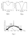
- Figures 5 and 6 illustrate the filter gain as a function of frequency for two different values of tap coefficient a. Particularly, negative values of the tap coefficient a result in amplification of the high frequency spectral components with respect to the central frequency component at f 0 .
- the pre-emphasis of high frequency components is increased. Indeed the equalizer response in Figure 6 has a more pronounced pre-emphasis of high frequency components than equalizer response in Figure 5 .
- Figure 7 shows the spectrum of the same 4-ASK modulated signal 10 as discussed in figure 2 , where the driving signals are now spectrally equalized with the transfer function shown in Figure 6 .
- the filtering reduces the power discrepancy between low and high frequency components of the modulated signal.
- the equalized spectrum is more flat so that the corresponding eye diagram is as more open.
- the optimal configuration of the equalizer 11 bringing the best performance is determined automatically as a function of the characteristics of both the electrical driver and the optical modulator. This is especially useful if the optical receiver 15 that is employed at the destination relies on quadratic direct detection.
- the transmitter of Figure 3 further comprises a feedback loop 20.
- a quality assessment module 21 assesses the quality of the equalized signal and provides a quality measurement signal 23 to a control module 22 that reconfigures the FFE 11 as a function of the measurement.
- the quality assessment module 21 measures the flatness of the spectrum through spectral analysis as shown by arrow 24 or the opening of the eye diagram through time domain analysis as shown by arrow 25.
- the control module 22 selects an optimal equalizer configuration that yields the best quality of the 4-ASK equalized signal either by tuning the filter coefficients or by selecting predefined filter profiles stored in a look-up table.
- the quality assessment module 21 comprises a pair of band pass filters 31 and 32 to measure the power spectral density of the signal at different frequencies, typically in first a frequency band 33 close to the carrier frequency f 0 and a second frequency band 34 located at 0.7xR from the carrier frequency f 0 .
- the quality assessment module 21 computes the power ratio in dB obtained from these two measurements and provides that data as the measurement signal 23 to the control module 22.
- the control module 22 compares the computed ratio to a preset target value.
- the target value can be defined using a calibration process. In the example shown in Figure 7 , the power ratio of 5 dB between low and high frequency components is considered as a suitable target value.
- control module 22 adjusts the filter 11, e.g. the absolute value of the delay-tap coefficient a of the filter 11 is increased.
- I k stands for the mean value of the k-th level of the signal and ⁇ k stands for its standard deviation.
- equalization is performed in the electrical domain using the FFE 11.
- an optical spectral equalizer e.g. a device known as WaveShaper ® available from Finisar Corp. USA.
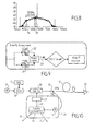
- a corresponding embodiment is illustrated in Figure 10 , where the optical spectral equalizer 30 is arranged between the MZM 8 and the optical splitter 12.
- a similar feedback loop 20 can be applied whatever the type of equalization chosen, either electrical as in Figure 3 or optical as in Figure 10 .
- an amplifier is arranged between DAC 7 and optical modulator 8.
- Elements such as the quality assessment and control modules could be e.g. hardware means like e.g. an ASIC, or a combination of hardware and software means, e.g. an ASIC and an FPGA, or at least one microprocessor and at least one memory with software modules located therein.
Landscapes
- Physics & Mathematics (AREA)
- Electromagnetism (AREA)
- Engineering & Computer Science (AREA)
- Computer Networks & Wireless Communication (AREA)
- Signal Processing (AREA)
- Optics & Photonics (AREA)
- Optical Communication System (AREA)
- Digital Transmission Methods That Use Modulated Carrier Waves (AREA)
Abstract
Description
- The invention relates to the technical field of optical communication systems, in particular communications systems employing multilevel amplitude-shift-keying (ASK) modulation schemes.
- Optical fiber transmissions employing coherent detection make it possible to achieve very high data rates over long distances, e.g. typically 100Gb/s per wavelength channel. However coherent detection solutions may be too expensive for some applications, e.g. short reach transmissions. Therefore a need exists for optical transmission techniques that achieve a high data rate and remain compatible with direct detection of the signal intensity, i.e. quadratic detection, at the destination node.
- In an embodiment, the invention provides an optical transmitter for transmitting a multilevel amplitude-shift-keying modulated signal, comprising:
- an optical modulator for modulating an optical signal with a multilevel amplitude-shift-keying modulation, and
- a spectral filter adapted to increase a high-frequency component of the modulated optical signal relatively to a central frequency component.
- According to embodiments, such optical transmitters can comprise one or more of the features below.
- In embodiments, the multilevel ASK modulation is quaternary ASK.
- In embodiments, the symbol rate of the optical modulator is above 40Gbaud, for example about 56Gbaud.
- In embodiments, the high-frequency component of the modulated optical signal comprises a frequency higher than f0+0.5R, wherein f0 is a central frequency of the optical signal and R is the symbol rate of the optical modulator.
- In embodiments, the high-frequency component of the modulated optical signal comprises a frequency equal to f0+0.7R.
- In embodiments, the spectral filter comprises a Feed Forward filter arranged to filter a baseband electrical signal that drives the optical modulator.
- In embodiments, the Feed Forward filter comprises a single delay-tap with a negative configurable delay-tap coefficient.
- In embodiments, the Feed Forward filter comprises a plurality of delay-taps with a plurality of configurable delay-tap coefficients.
- In embodiments, the spectral filter comprises an optical spectral equalizer for equalizing the modulated optical signal
- In embodiments, the optical transmitter further comprises a feedback loop including a quality measurement module for measuring a quality of the transmitted optical signal and a feedback controller for reconfiguring the spectral filter as a function of the measured quality.
- In embodiments, the quality measurement module is adapted to measure an eye-diagram opening of the transmitted optical signal.
- In embodiments, the quality measurement module is adapted to measure a power ratio between the high-frequency component of the transmitted optical signal and the central frequency component of the transmitted optical signal.
- In embodiments, the feedback controller is adapted to increase the absolute value of a negative delay-tap coefficient of the Feed Forward filter in response to the measured eye-diagram opening or power ratio being lower than a target value.
- In embodiments, the feedback controller is adapted to increase the gain of a high-frequency channel of the optical spectral equalizer in response to the measured eye-diagram opening or power ratio being lower than a target value.
- In embodiments, the optical transmitter further comprises a laser source for generating the optical signal.
- In an embodiment, the invention also provides an optical communication system comprising:
- the above mentioned optical transmitter,
- an optical receiver, and
- an optical link connecting the optical receiver to the optical transmitter in the optical domain.
- According to embodiments, such optical communication systems can comprise one or more of the features below.
- In embodiments, the optical receiver is a quadratic direct detection receiver.
- In embodiments, a range of the optical communication system is shorter than 100 km, preferably shorter than 10 km.
- Aspects of the invention are based on the idea of generating a high-rate multilevel ASK signal that can be successfully demodulated with a quadratic direct detection receiver. Aspects of the invention stem for the observation that power equalization makes it possible to reduce inter-symbol interferences in a high-rate multilevel ASK signal. Aspects of the invention are based on the idea of employing a feedback loop to update the coefficients of a spectral filter to maintain an optimal configuration of the spectral filter.
- These and other aspects of the invention will be apparent from and elucidated with reference to the embodiments described hereinafter, by way of example, with reference to the drawings.
-
Figure 1 is a functional representation of an optical transmitter suitable for generating a quaternary ASK-modulated optical signal. -
Figure 2 is a graph showing the power spectrum of a quaternary ASK-modulated optical signal. -
Figure 3 is a functional representation of an optical transmitter in accordance with an embodiment. -
Figure 4 is a functional representation of a Feed Forward filter employed in the optical transmitter ofFigure 3 . -
Figures 5 and 6 are two graphs showing the transfer function of the filter ofFigure 4 for two different values of the single tap coefficient. -
Figure 7 is a graph showing the power spectrum of a quaternary ASK-modulated optical signal obtainable with the transmitter ofFigure 3 . -
Figure 8 is a graph showing the power spectrum of a quaternary ASK-modulated optical signal and two spectral bands monitored by a quality assessment module. -
Figure 9 is a flow chart showing the operations of a feedback loop in an embodiment. -
Figure 10 is a functional representation of an optical transmitter in accordance with another embodiment. -
Figure 1 shows anoptical transmitter 1 for generating a modulated optical signal at 100Gb/s based on 4-level amplitude shift keying (4-ASK). Such a 4-ASK modulated signal can be used for short reach transmissions using direct detection. - The
transmitter 1 comprises abinary signal generator 2 that generates four NRZ-codedbinary streams 3 at a clock rate of 28 GHz. Two multiplexers 4 are arranged to receive twobinary streams 3 each. The multiplexer 4 is driven by aclock signal 5 at 56 GHz to interleave bothbinary streams 3 into a 56 Gb/s NRZ-codedbinary stream 6. Both of the resulting 56 Gb/sbinary streams 6 are fed to a 2-bits digital-to-analog converter 7 that generates a 4-level driving signal I and the complementary 4-level signalI to drive a Mach-Zehnder modulator 8 (MZM) in a push-pull mode. - The push-pull mode means that binary driving signals having mutually reversed phases are input to a data input terminal and an inverted data input terminal of the
MZM 8 and the peak voltages of those binary driving signals are set to a half wavelength voltage of the Mach-Zehnder interferometer. - The MZM 8 receive an optical carrier wave from a laser source 9 and outputs a modulated
optical signal 10 carrying a 4-ASK modulation at a symbol rate R=56 Gbaud, i.e. equivalent to 112 Gb/s. - The power spectrum of the resulting
modulated signal 10 can be seen inFigure 2 . The ability to generate the multi-level modulated signal at such a high baud rate is limited by the combined bandwidth of theelectrical drivers 7 and theoptical modulator 8. Commercial optical modulators with low Voltage drive usually have 3dB-bandwidth below 35GHz. - The bandwidth limitation of the transmitter induces large filtering of high frequency components, yielding a quite closed 4-level optical eye diagram. The bandwidth limitation for the 56Gbaud 4-
ASK signal 10 is rendered visible by the 12 dB attenuation of the spectral components located at 0.7xR from the carrier frequency f0 inFigure 2 . These limitations induce inter-symbol interferences (ISI) that severely degrade the performance of the transmitter. - Equalization can be employed to mitigate such bandwidth limitations by enhancing spectral content at high frequencies. For instance, feed forward equalizers (FFE) can be used and implemented either in the electrical or the optical domain.
- With reference to
Figures 3 to 10 , there will now be described embodiments of a similar optical transmitter in which optical or electrical spectral equalization is employed to mitigate the inter-symbol interferences (ISI) induced penalties. Elements identical or similar to those ofFigure 1 are designated by the same numeral as inFigure 1 . - In the embodiment of
Figure 4 , spectral equalization is achieved in the electrical domain by aFeed Forward Equalizer 11 arranged between the digital-to-analog converter 7 and theoptical modulator 8. An amplifier may also be arranged betweenDAC 7 andFeed Forward Equalizer 11. - In an embodiment depicted in
Figure 4 , theFFE 11 is a single delay-tap equalizer having a single tap coefficient a. InFigure 4 , τ designates the delay of one symbol. The transfer function H(f) of this single delay-tap equalizer is:
-
Figures 5 and 6 illustrate the filter gain as a function of frequency for two different values of tap coefficient a. Particularly, negative values of the tap coefficient a result in amplification of the high frequency spectral components with respect to the central frequency component at f0. By increasing the absolute value of the delay-tap coefficient a, the pre-emphasis of high frequency components is increased. Indeed the equalizer response inFigure 6 has a more pronounced pre-emphasis of high frequency components than equalizer response inFigure 5 . - By adjusting the delay-tap coefficient a, the transfer function H(f) of the equalizer can be modified to provide an optimal amplification of the high frequency components that have been attenuated by the electrical driver, e.g. the high-frequency component at

-
Figure 7 shows the spectrum of the same 4-ASK modulatedsignal 10 as discussed infigure 2 , where the driving signals are now spectrally equalized with the transfer function shown inFigure 6 . - The filtering reduces the power discrepancy between low and high frequency components of the modulated signal. As can be seen in
Figure 7 , the equalized spectrum is more flat so that the corresponding eye diagram is as more open. - In a preferred embodiment, the optimal configuration of the
equalizer 11 bringing the best performance is determined automatically as a function of the characteristics of both the electrical driver and the optical modulator. This is especially useful if theoptical receiver 15 that is employed at the destination relies on quadratic direct detection. - In order to adjust the equalizer response as a function of the characteristics of the 4-
ASK transmitter 1, the transmitter ofFigure 3 further comprises afeedback loop 20. Using a 1%optical splitter 12 followed by awideband photodiode 13, aquality assessment module 21 assesses the quality of the equalized signal and provides aquality measurement signal 23 to acontrol module 22 that reconfigures theFFE 11 as a function of the measurement. For example, thequality assessment module 21 measures the flatness of the spectrum through spectral analysis as shown byarrow 24 or the opening of the eye diagram through time domain analysis as shown byarrow 25. - The
control module 22 selects an optimal equalizer configuration that yields the best quality of the 4-ASK equalized signal either by tuning the filter coefficients or by selecting predefined filter profiles stored in a look-up table. - In an embodiment depicted in
Figures 8 and 9 , thequality assessment module 21 comprises a pair of band pass filters 31 and 32 to measure the power spectral density of the signal at different frequencies, typically in first afrequency band 33 close to the carrier frequency f0 and asecond frequency band 34 located at 0.7xR from the carrier frequency f0. To assess the balance between low and high frequency spectral components, thequality assessment module 21 computes the power ratio in dB obtained from these two measurements and provides that data as themeasurement signal 23 to thecontrol module 22. Thecontrol module 22 compares the computed ratio to a preset target value. The target value can be defined using a calibration process. In the example shown inFigure 7 , the power ratio of 5 dB between low and high frequency components is considered as a suitable target value. - If the computed ratio is above the preset target, the
control module 22 adjusts thefilter 11, e.g. the absolute value of the delay-tap coefficient a of thefilter 11 is increased. - In an embodiment, the
quality assessment module 21 measures the opening of the eye diagram by computing a Time domain quality factor defined as:
- Where Ik stands for the mean value of the k-th level of the signal and σk stands for its standard deviation.
- In the above embodiment, equalization is performed in the electrical domain using the
FFE 11. However, the same equalization could be performed in the optical domain using an optical spectral equalizer, e.g. a device known as WaveShaper ® available from Finisar Corp. USA. A corresponding embodiment is illustrated inFigure 10 , where the opticalspectral equalizer 30 is arranged between theMZM 8 and theoptical splitter 12. Asimilar feedback loop 20 can be applied whatever the type of equalization chosen, either electrical as inFigure 3 or optical as inFigure 10 . In an embodiment, an amplifier is arranged betweenDAC 7 andoptical modulator 8. - The above transmitters have been successfully tested in a short reach optical communication system with an
optical link 17 of 1 km. However, the achievable range of such systems depends on a number of parameters as will be appreciated by those skilled in the art. Optical amplifiers and electrical amplifiers can be arranged at different points in the system to adjust the range. - Elements such as the quality assessment and control modules could be e.g. hardware means like e.g. an ASIC, or a combination of hardware and software means, e.g. an ASIC and an FPGA, or at least one microprocessor and at least one memory with software modules located therein.
- The invention is not limited to the described embodiments. The appended claims are to be construed as embodying all modification and alternative constructions that may be occurred to one skilled in the art, which fairly fall within the basic teaching here, set forth.
- The use of the verb "to comprise" or "to include" and its conjugations does not exclude the presence of elements or steps other than those stated in a claim. Furthermore, the use of the article "a" or "an" preceding an element or step does not exclude the presence of a plurality of such elements or steps.
- In the claims, any reference signs placed between parentheses shall not be construed as limiting the scope of the claims.
Claims (15)
- An optical transmitter for transmitting a multilevel amplitude-shift-keying modulated signal, comprising:an optical modulator (8) for modulating an optical signal with a multilevel amplitude-shift-keying modulation, anda spectral filter (11, 30) adapted to increase a high-frequency component (34) of the modulated optical signal relatively to a central frequency component (33).
- An optical transmitter in accordance with claim 1, wherein the multilevel ASK modulation is quaternary ASK.
- An optical transmitter in accordance with claim 1 or 2, wherein the symbol rate of the optical modulator is above 40Gbaud.
- An optical transmitter in accordance with any one of claims 1 to 3, wherein the high-frequency component (34) of the modulated optical signal comprises a frequency higher than f0+0.5R, wherein f0 is a central frequency of the optical signal and R is the symbol rate of the optical modulator.
- An optical transmitter in accordance with claim 4, wherein the high-frequency component (34) of the modulated optical signal comprises a frequency equal to f0+0.7R.
- An optical transmitter in accordance with one of claims 1 to 5, wherein the spectral filter comprises a Feed Forward filter (11) arranged to filter a baseband electrical signal that drives the optical modulator (8).
- An optical transmitter in accordance with claim 6, wherein the Feed Forward filter (11) comprises a single delay-tap with a negative configurable delay-tap coefficient.
- An optical transmitter in accordance with claim 6, wherein the Feed Forward filter comprises a plurality of delay-taps with a plurality of configurable delay-tap coefficients.
- An optical transmitter in accordance with one of claims 1 to 8, wherein the spectral filter comprises an optical spectral equalizer (30) for equalizing the modulated optical signal.
- An optical transmitter in accordance with any one of claims 1 to 9, further comprising a feedback loop (20) including a quality measurement module (21) for measuring a quality of the transmitted optical signal and a feedback controller (22) for reconfiguring the spectral filter as a function of the measured quality.
- An optical transmitter in accordance with claim 10, wherein the quality measurement module (21) is adapted to measure an eye-diagram opening (25) of the transmitted optical signal.
- An optical transmitter in accordance with claim 10, wherein the quality measurement module (21) is adapted to measure a power ratio (23) between the high-frequency component of the transmitted optical signal and the central frequency component of the transmitted optical signal.
- An optical transmitter in accordance with any one of claims 11 to 12 taken in combination with claim 6, wherein the feedback controller (22) is adapted to increase the absolute value of a negative delay-tap coefficient of the Feed Forward filter in response to the measured eye-diagram opening or power ratio being lower than a target value.
- An optical transmitter in accordance with any one of claims 11 to 12 taken in combination with claim 9, wherein the feedback controller (22) is adapted to increase the gain of a high-frequency channel of the optical spectral equalizer (30) in response to the measured eye-diagram opening or power ratio being lower than a target value.
- A optical communication system comprising:an optical transmitter in accordance with any one of claims 1 to 14,an optical receiver (15), andan optical link (17) connecting the optical receiver to the optical transmitter in the optical domain, wherein the optical receiver is a quadratic direct detection receiver and wherein a range of the optical communication system is shorter than 100 km.
Priority Applications (6)
| Application Number | Priority Date | Filing Date | Title |
|---|---|---|---|
| EP12177022.6A EP2688232B1 (en) | 2012-07-19 | 2012-07-19 | Optical transmitter for transmitting a multilevel amplitude-shift-keying modulated signal |
| KR1020157000823A KR101645956B1 (en) | 2012-07-19 | 2013-06-21 | Optical transmitter for transmitting a multilevel amplitude-shift-keying modulated signal |
| JP2015522019A JP6140281B2 (en) | 2012-07-19 | 2013-06-21 | Optical transmitter for transmitting multi-level amplitude shift keying modulated signal |
| PCT/EP2013/063015 WO2014012745A1 (en) | 2012-07-19 | 2013-06-21 | Optical transmitter for transmitting a multilevel amplitude-shift-keying modulated signal |
| US14/413,071 US9621276B2 (en) | 2012-07-19 | 2013-06-21 | Optical transmitter for transmitting a multilevel amplitude-shift-keying modulated signal |
| CN201380038125.7A CN104509003B (en) | 2012-07-19 | 2013-06-21 | Optical transmitter for transmitting multi-level amplitude keying modulated signal |
Applications Claiming Priority (1)
| Application Number | Priority Date | Filing Date | Title |
|---|---|---|---|
| EP12177022.6A EP2688232B1 (en) | 2012-07-19 | 2012-07-19 | Optical transmitter for transmitting a multilevel amplitude-shift-keying modulated signal |
Publications (2)
| Publication Number | Publication Date |
|---|---|
| EP2688232A1 true EP2688232A1 (en) | 2014-01-22 |
| EP2688232B1 EP2688232B1 (en) | 2017-06-14 |
Family
ID=48741078
Family Applications (1)
| Application Number | Title | Priority Date | Filing Date |
|---|---|---|---|
| EP12177022.6A Active EP2688232B1 (en) | 2012-07-19 | 2012-07-19 | Optical transmitter for transmitting a multilevel amplitude-shift-keying modulated signal |
Country Status (6)
| Country | Link |
|---|---|
| US (1) | US9621276B2 (en) |
| EP (1) | EP2688232B1 (en) |
| JP (1) | JP6140281B2 (en) |
| KR (1) | KR101645956B1 (en) |
| CN (1) | CN104509003B (en) |
| WO (1) | WO2014012745A1 (en) |
Families Citing this family (8)
| Publication number | Priority date | Publication date | Assignee | Title |
|---|---|---|---|---|
| EP2688232B1 (en) * | 2012-07-19 | 2017-06-14 | Alcatel Lucent | Optical transmitter for transmitting a multilevel amplitude-shift-keying modulated signal |
| US10038503B2 (en) * | 2014-08-13 | 2018-07-31 | Xilinx, Inc. | Adaptive optical channel compensation |
| TWI580215B (en) * | 2015-07-31 | 2017-04-21 | 群聯電子股份有限公司 | Signal modulation method, adaptive equalizer and memory storage device |
| US10193634B2 (en) * | 2016-09-19 | 2019-01-29 | Hewlett Packard Enterprise Development Lp | Optical driver circuits |
| WO2019033242A1 (en) * | 2017-08-14 | 2019-02-21 | 华为技术有限公司 | Method and apparatus for determining tap coefficient of filter |
| TWI642063B (en) * | 2017-10-13 | 2018-11-21 | 群聯電子股份有限公司 | Equalizer tuning method, signal receiving circuit and a memory storage device |
| CN112910563B (en) * | 2021-01-26 | 2023-05-02 | 中国科学院半导体研究所 | Signal generating device and method |
| JP2022150173A (en) * | 2021-03-26 | 2022-10-07 | 富士通株式会社 | Optical transmitter and transmission device |
Citations (3)
| Publication number | Priority date | Publication date | Assignee | Title |
|---|---|---|---|---|
| EP0877495A2 (en) * | 1997-04-09 | 1998-11-11 | Matsushita Electric Industrial Co., Ltd. | Optical transmitter-receiver |
| JP2000019470A (en) * | 1998-06-29 | 2000-01-21 | Nippon Hoso Kyokai <Nhk> | Optical transmitter for optical fiber transmission of ASK high-frequency signal |
| US20070222654A1 (en) * | 2001-03-29 | 2007-09-27 | Quellan, Inc. | Increasing data throughput in optical fiber transmission systems |
Family Cites Families (32)
| Publication number | Priority date | Publication date | Assignee | Title |
|---|---|---|---|---|
| JPH0371118A (en) | 1989-08-11 | 1991-03-26 | Hitachi Ltd | Optical group delay equalizing system |
| DE69932759T2 (en) * | 1998-01-27 | 2006-12-28 | Matsushita Electric Industrial Co., Ltd., Kadoma | Optical FM signal transmitter |
| GB2370473B (en) * | 2000-12-21 | 2004-04-07 | Marconi Caswell Ltd | Improvements in or relating to optical communication |
| JP2003143076A (en) * | 2001-10-30 | 2003-05-16 | Nippon Telegr & Teleph Corp <Ntt> | Optical transmission circuit |
| US7382984B2 (en) * | 2002-10-03 | 2008-06-03 | Nortel Networks Limited | Electrical domain compensation of optical dispersion in an optical communications system |
| US20050069330A1 (en) | 2003-09-29 | 2005-03-31 | Yuan-Hua Kao | System and method for optical transmission |
| JP4573871B2 (en) | 2005-02-28 | 2010-11-04 | 富士通株式会社 | Demodulation circuit and electronic equipment |
| JP4717557B2 (en) * | 2005-08-30 | 2011-07-06 | 三菱電機株式会社 | Communication system and transmitter / receiver |
| AU2008314499A1 (en) * | 2007-10-15 | 2009-04-23 | Ofidium Pty Ltd | Method and apparatus for improving reception of optical signals |
| CN101420636A (en) | 2007-10-26 | 2009-04-29 | 北京邮电大学 | Apparatus and method for effectively bearing mark and load by single DFB laser |
| JP4888567B2 (en) * | 2007-11-08 | 2012-02-29 | 富士通株式会社 | Coherent optical receiver |
| IL187836A0 (en) * | 2007-12-03 | 2008-03-20 | Eci Telecom Ltd | Technique for generating multilevel coded optical signals |
| CN101394232A (en) | 2007-12-17 | 2009-03-25 | 北京邮电大学 | A Device and Method for Inserting and Erasing Optical Marks Based on SOA-MZI |
| JP4828514B2 (en) * | 2007-12-18 | 2011-11-30 | 日本電信電話株式会社 | Electric dispersion equalization circuit |
| US20090304395A1 (en) * | 2008-06-05 | 2009-12-10 | Jin Hong | Tunable Electrical Return-to-Zero Modulation Method and Apparatus |
| JP2010068029A (en) * | 2008-09-08 | 2010-03-25 | Sumitomo Electric Ind Ltd | Optical transceiver |
| US8351799B2 (en) * | 2008-10-06 | 2013-01-08 | Telcordia Technologies, Inc. | Multiscale sampling for wide dynamic range electro-optic receivers |
| US8135288B2 (en) * | 2009-02-03 | 2012-03-13 | The Boeing Company | System and method for a photonic system |
| JP5334747B2 (en) * | 2009-08-21 | 2013-11-06 | 日本電信電話株式会社 | Optical code division multiplexing transmission system and optical code division multiplexing transmission method |
| WO2011044959A1 (en) * | 2009-10-13 | 2011-04-21 | Nokia Siemens Networks Gmbh & Co. Kg | Method for processing data in an optical network element and optical network element |
| JP4972696B2 (en) * | 2010-02-02 | 2012-07-11 | 株式会社日立製作所 | Optical transmission circuit and optical communication system |
| US8588290B2 (en) * | 2010-09-02 | 2013-11-19 | Lsi Corporation | Adaptation of crossing latch threshold |
| US8831439B2 (en) * | 2010-10-05 | 2014-09-09 | Infinera Corporation | Upsampling optical transmitter |
| CN103141037B (en) * | 2010-11-30 | 2016-03-30 | 三菱电机株式会社 | Light conveying system, light sending device and optical pickup apparatus |
| US8543009B2 (en) * | 2010-12-03 | 2013-09-24 | Raytheon Company | Method and apparatus for synthesizing ultra-wide bandwidth waveforms |
| FR2969885B1 (en) * | 2010-12-23 | 2013-01-18 | St Microelectronics Grenoble 2 | QUICK BLACK CHANNEL SEARCH SYSTEM |
| US9048954B2 (en) * | 2011-03-02 | 2015-06-02 | International Business Machines Corporation | Optical interconnect using optical transmitter pre-distortion |
| US9136948B2 (en) * | 2011-07-27 | 2015-09-15 | Cisco Technology, Inc. | Electrical modulator driver circuit for generating multi-level drive signals for QAM optical transmission |
| US20130058642A1 (en) * | 2011-09-01 | 2013-03-07 | Fujitsu Limited | Method and system for conserving power in an optical network |
| EP2688232B1 (en) * | 2012-07-19 | 2017-06-14 | Alcatel Lucent | Optical transmitter for transmitting a multilevel amplitude-shift-keying modulated signal |
| US8923706B2 (en) * | 2012-07-24 | 2014-12-30 | Alcatel Lucent | Frequency equalization for an optical transmitter |
| US8451528B1 (en) * | 2012-09-13 | 2013-05-28 | Ram Photonics, LLC | Method and apparatus for generation of coherent frequency combs |
-
2012
- 2012-07-19 EP EP12177022.6A patent/EP2688232B1/en active Active
-
2013
- 2013-06-21 CN CN201380038125.7A patent/CN104509003B/en active Active
- 2013-06-21 WO PCT/EP2013/063015 patent/WO2014012745A1/en not_active Ceased
- 2013-06-21 KR KR1020157000823A patent/KR101645956B1/en not_active Expired - Fee Related
- 2013-06-21 US US14/413,071 patent/US9621276B2/en active Active
- 2013-06-21 JP JP2015522019A patent/JP6140281B2/en not_active Expired - Fee Related
Patent Citations (3)
| Publication number | Priority date | Publication date | Assignee | Title |
|---|---|---|---|---|
| EP0877495A2 (en) * | 1997-04-09 | 1998-11-11 | Matsushita Electric Industrial Co., Ltd. | Optical transmitter-receiver |
| JP2000019470A (en) * | 1998-06-29 | 2000-01-21 | Nippon Hoso Kyokai <Nhk> | Optical transmitter for optical fiber transmission of ASK high-frequency signal |
| US20070222654A1 (en) * | 2001-03-29 | 2007-09-27 | Quellan, Inc. | Increasing data throughput in optical fiber transmission systems |
Also Published As
| Publication number | Publication date |
|---|---|
| CN104509003A (en) | 2015-04-08 |
| EP2688232B1 (en) | 2017-06-14 |
| CN104509003B (en) | 2017-05-31 |
| KR101645956B1 (en) | 2016-08-05 |
| WO2014012745A1 (en) | 2014-01-23 |
| US9621276B2 (en) | 2017-04-11 |
| KR20150023730A (en) | 2015-03-05 |
| JP2015529040A (en) | 2015-10-01 |
| US20150207570A1 (en) | 2015-07-23 |
| JP6140281B2 (en) | 2017-05-31 |
Similar Documents
| Publication | Publication Date | Title |
|---|---|---|
| EP2688232B1 (en) | Optical transmitter for transmitting a multilevel amplitude-shift-keying modulated signal | |
| US9544060B2 (en) | Optical transmitter and method for controlling the same | |
| US8503887B2 (en) | Pre-equalized optical transmitter and pre-equalized optical transmission system | |
| US10958343B1 (en) | Method and apparatus for distortion correction in optical communication links | |
| US8107826B2 (en) | Methods and apparatus for optical transmission of digital signals | |
| US9735883B2 (en) | Intensity modulated direct detection optical transceiver | |
| US8705981B2 (en) | Driver circuit of optical modulator | |
| US20060029358A1 (en) | Optical system comprising an FM source and a spectral reshaping element | |
| US8571416B2 (en) | Dual polarization transceiver | |
| CN101310458A (en) | Method and device for optical transmission of digital signals | |
| US20120281981A1 (en) | Method and apparatus for detecting chromatic dispersion, and method and apparatus for compensating chromatic dispersion | |
| EP4283887A2 (en) | Methods and apparatus for detecting and compensating bandwidth limitation and modulation nonlinearity of a coherent optical transponder | |
| US12101125B2 (en) | Method of operating a bidirectional optical transmission link and corresponding optical transmission link | |
| Napoli et al. | On the next generation bandwidth variable transponders for future flexible optical systems | |
| Zheng et al. | Pushing capacity limits with multi-segment SiP modulators | |
| CA2557150A1 (en) | Optical system comprising an fm source and a spectral reshaping element | |
| Duan et al. | Experimental demonstration of DSP-enabled drop operations of flexible ROADMs excluding optical filters and OEO conversions | |
| EP3345314B1 (en) | Phase retrieval for compensation of chromatic dispersion-induced inter-symbol interference | |
| Xing et al. | 100Gb/s 16-QAM Transmission over 80 km SSMF using a silicon photonic modulator enabled VSB-IM/DD system | |
| Sharifian | Chromatic dispersion compensation by signal predistortion: Linear and nonlinear filtering | |
| Maram et al. | Semi-Analytical Methodology for Advanced Filter Design in Chirped-Managed Lasers | |
| US8064778B2 (en) | Method and apparatus for controlling tunable transmitter chirp | |
| CN119790611A (en) | Millimeter wave communication system | |
| Rozorynov et al. | Development of modulation formats in optical fiber communication channel | |
| VIGANÒ | Performance analysis of intensity modulated PAM-4 with pre-compensation filter and direct detection in short reach optical communication |
Legal Events
| Date | Code | Title | Description |
|---|---|---|---|
| PUAI | Public reference made under article 153(3) epc to a published international application that has entered the european phase |
Free format text: ORIGINAL CODE: 0009012 |
|
| AK | Designated contracting states |
Kind code of ref document: A1 Designated state(s): AL AT BE BG CH CY CZ DE DK EE ES FI FR GB GR HR HU IE IS IT LI LT LU LV MC MK MT NL NO PL PT RO RS SE SI SK SM TR |
|
| AX | Request for extension of the european patent |
Extension state: BA ME |
|
| 111Z | Information provided on other rights and legal means of execution |
Free format text: AL AT BE BG CH CY CZ DE DK EE ES FI FR GB GR HR HU IE IS IT LI LT LU LV MC MK MT NL NO PL PT RO RS SE SI SK SM TR Effective date: 20140516 |
|
| RAP1 | Party data changed (applicant data changed or rights of an application transferred) |
Owner name: ALCATEL LUCENT |
|
| 17P | Request for examination filed |
Effective date: 20140722 |
|
| RBV | Designated contracting states (corrected) |
Designated state(s): AL AT BE BG CH CY CZ DE DK EE ES FI FR GB GR HR HU IE IS IT LI LT LU LV MC MK MT NL NO PL PT RO RS SE SI SK SM TR |
|
| D11X | Information provided on other rights and legal means of execution (deleted) | ||
| REG | Reference to a national code |
Ref country code: DE Ref legal event code: R079 Ref document number: 602012033367 Country of ref document: DE Free format text: PREVIOUS MAIN CLASS: H04B0010500000 Ipc: H04B0010564000 |
|
| GRAP | Despatch of communication of intention to grant a patent |
Free format text: ORIGINAL CODE: EPIDOSNIGR1 |
|
| RIC1 | Information provided on ipc code assigned before grant |
Ipc: H04B 10/54 20130101ALI20161219BHEP Ipc: H04B 10/50 20130101ALI20161219BHEP Ipc: H04B 10/564 20130101AFI20161219BHEP |
|
| INTG | Intention to grant announced |
Effective date: 20170111 |
|
| GRAS | Grant fee paid |
Free format text: ORIGINAL CODE: EPIDOSNIGR3 |
|
| GRAA | (expected) grant |
Free format text: ORIGINAL CODE: 0009210 |
|
| AK | Designated contracting states |
Kind code of ref document: B1 Designated state(s): AL AT BE BG CH CY CZ DE DK EE ES FI FR GB GR HR HU IE IS IT LI LT LU LV MC MK MT NL NO PL PT RO RS SE SI SK SM TR |
|
| REG | Reference to a national code |
Ref country code: GB Ref legal event code: FG4D |
|
| REG | Reference to a national code |
Ref country code: CH Ref legal event code: EP Ref country code: AT Ref legal event code: REF Ref document number: 901874 Country of ref document: AT Kind code of ref document: T Effective date: 20170615 |
|
| REG | Reference to a national code |
Ref country code: IE Ref legal event code: FG4D |
|
| REG | Reference to a national code |
Ref country code: FR Ref legal event code: PLFP Year of fee payment: 6 |
|
| REG | Reference to a national code |
Ref country code: DE Ref legal event code: R096 Ref document number: 602012033367 Country of ref document: DE |
|
| REG | Reference to a national code |
Ref country code: NL Ref legal event code: MP Effective date: 20170614 |
|
| REG | Reference to a national code |
Ref country code: LT Ref legal event code: MG4D |
|
| PG25 | Lapsed in a contracting state [announced via postgrant information from national office to epo] |
Ref country code: HR Free format text: LAPSE BECAUSE OF FAILURE TO SUBMIT A TRANSLATION OF THE DESCRIPTION OR TO PAY THE FEE WITHIN THE PRESCRIBED TIME-LIMIT Effective date: 20170614 Ref country code: FI Free format text: LAPSE BECAUSE OF FAILURE TO SUBMIT A TRANSLATION OF THE DESCRIPTION OR TO PAY THE FEE WITHIN THE PRESCRIBED TIME-LIMIT Effective date: 20170614 Ref country code: NO Free format text: LAPSE BECAUSE OF FAILURE TO SUBMIT A TRANSLATION OF THE DESCRIPTION OR TO PAY THE FEE WITHIN THE PRESCRIBED TIME-LIMIT Effective date: 20170914 Ref country code: GR Free format text: LAPSE BECAUSE OF FAILURE TO SUBMIT A TRANSLATION OF THE DESCRIPTION OR TO PAY THE FEE WITHIN THE PRESCRIBED TIME-LIMIT Effective date: 20170915 Ref country code: LT Free format text: LAPSE BECAUSE OF FAILURE TO SUBMIT A TRANSLATION OF THE DESCRIPTION OR TO PAY THE FEE WITHIN THE PRESCRIBED TIME-LIMIT Effective date: 20170614 |
|
| REG | Reference to a national code |
Ref country code: AT Ref legal event code: MK05 Ref document number: 901874 Country of ref document: AT Kind code of ref document: T Effective date: 20170614 |
|
| PG25 | Lapsed in a contracting state [announced via postgrant information from national office to epo] |
Ref country code: BG Free format text: LAPSE BECAUSE OF FAILURE TO SUBMIT A TRANSLATION OF THE DESCRIPTION OR TO PAY THE FEE WITHIN THE PRESCRIBED TIME-LIMIT Effective date: 20170914 Ref country code: LV Free format text: LAPSE BECAUSE OF FAILURE TO SUBMIT A TRANSLATION OF THE DESCRIPTION OR TO PAY THE FEE WITHIN THE PRESCRIBED TIME-LIMIT Effective date: 20170614 Ref country code: NL Free format text: LAPSE BECAUSE OF FAILURE TO SUBMIT A TRANSLATION OF THE DESCRIPTION OR TO PAY THE FEE WITHIN THE PRESCRIBED TIME-LIMIT Effective date: 20170614 Ref country code: RS Free format text: LAPSE BECAUSE OF FAILURE TO SUBMIT A TRANSLATION OF THE DESCRIPTION OR TO PAY THE FEE WITHIN THE PRESCRIBED TIME-LIMIT Effective date: 20170614 Ref country code: SE Free format text: LAPSE BECAUSE OF FAILURE TO SUBMIT A TRANSLATION OF THE DESCRIPTION OR TO PAY THE FEE WITHIN THE PRESCRIBED TIME-LIMIT Effective date: 20170614 |
|
| PG25 | Lapsed in a contracting state [announced via postgrant information from national office to epo] |
Ref country code: RO Free format text: LAPSE BECAUSE OF FAILURE TO SUBMIT A TRANSLATION OF THE DESCRIPTION OR TO PAY THE FEE WITHIN THE PRESCRIBED TIME-LIMIT Effective date: 20170614 Ref country code: CZ Free format text: LAPSE BECAUSE OF FAILURE TO SUBMIT A TRANSLATION OF THE DESCRIPTION OR TO PAY THE FEE WITHIN THE PRESCRIBED TIME-LIMIT Effective date: 20170614 Ref country code: AT Free format text: LAPSE BECAUSE OF FAILURE TO SUBMIT A TRANSLATION OF THE DESCRIPTION OR TO PAY THE FEE WITHIN THE PRESCRIBED TIME-LIMIT Effective date: 20170614 Ref country code: EE Free format text: LAPSE BECAUSE OF FAILURE TO SUBMIT A TRANSLATION OF THE DESCRIPTION OR TO PAY THE FEE WITHIN THE PRESCRIBED TIME-LIMIT Effective date: 20170614 Ref country code: SK Free format text: LAPSE BECAUSE OF FAILURE TO SUBMIT A TRANSLATION OF THE DESCRIPTION OR TO PAY THE FEE WITHIN THE PRESCRIBED TIME-LIMIT Effective date: 20170614 |
|
| PG25 | Lapsed in a contracting state [announced via postgrant information from national office to epo] |
Ref country code: IT Free format text: LAPSE BECAUSE OF FAILURE TO SUBMIT A TRANSLATION OF THE DESCRIPTION OR TO PAY THE FEE WITHIN THE PRESCRIBED TIME-LIMIT Effective date: 20170614 Ref country code: PL Free format text: LAPSE BECAUSE OF FAILURE TO SUBMIT A TRANSLATION OF THE DESCRIPTION OR TO PAY THE FEE WITHIN THE PRESCRIBED TIME-LIMIT Effective date: 20170614 Ref country code: ES Free format text: LAPSE BECAUSE OF FAILURE TO SUBMIT A TRANSLATION OF THE DESCRIPTION OR TO PAY THE FEE WITHIN THE PRESCRIBED TIME-LIMIT Effective date: 20170614 Ref country code: SM Free format text: LAPSE BECAUSE OF FAILURE TO SUBMIT A TRANSLATION OF THE DESCRIPTION OR TO PAY THE FEE WITHIN THE PRESCRIBED TIME-LIMIT Effective date: 20170614 Ref country code: IS Free format text: LAPSE BECAUSE OF FAILURE TO SUBMIT A TRANSLATION OF THE DESCRIPTION OR TO PAY THE FEE WITHIN THE PRESCRIBED TIME-LIMIT Effective date: 20171014 |
|
| REG | Reference to a national code |
Ref country code: CH Ref legal event code: PL |
|
| REG | Reference to a national code |
Ref country code: DE Ref legal event code: R097 Ref document number: 602012033367 Country of ref document: DE |
|
| PG25 | Lapsed in a contracting state [announced via postgrant information from national office to epo] |
Ref country code: MC Free format text: LAPSE BECAUSE OF FAILURE TO SUBMIT A TRANSLATION OF THE DESCRIPTION OR TO PAY THE FEE WITHIN THE PRESCRIBED TIME-LIMIT Effective date: 20170614 |
|
| RAP2 | Party data changed (patent owner data changed or rights of a patent transferred) |
Owner name: ALCATEL LUCENT |
|
| REG | Reference to a national code |
Ref country code: IE Ref legal event code: MM4A |
|
| PLBE | No opposition filed within time limit |
Free format text: ORIGINAL CODE: 0009261 |
|
| STAA | Information on the status of an ep patent application or granted ep patent |
Free format text: STATUS: NO OPPOSITION FILED WITHIN TIME LIMIT |
|
| PG25 | Lapsed in a contracting state [announced via postgrant information from national office to epo] |
Ref country code: LI Free format text: LAPSE BECAUSE OF NON-PAYMENT OF DUE FEES Effective date: 20170731 Ref country code: CH Free format text: LAPSE BECAUSE OF NON-PAYMENT OF DUE FEES Effective date: 20170731 Ref country code: DK Free format text: LAPSE BECAUSE OF FAILURE TO SUBMIT A TRANSLATION OF THE DESCRIPTION OR TO PAY THE FEE WITHIN THE PRESCRIBED TIME-LIMIT Effective date: 20170614 Ref country code: IE Free format text: LAPSE BECAUSE OF NON-PAYMENT OF DUE FEES Effective date: 20170719 |
|
| 26N | No opposition filed |
Effective date: 20180315 |
|
| REG | Reference to a national code |
Ref country code: BE Ref legal event code: MM Effective date: 20170731 |
|
| PG25 | Lapsed in a contracting state [announced via postgrant information from national office to epo] |
Ref country code: LU Free format text: LAPSE BECAUSE OF NON-PAYMENT OF DUE FEES Effective date: 20170719 |
|
| REG | Reference to a national code |
Ref country code: FR Ref legal event code: PLFP Year of fee payment: 7 |
|
| PG25 | Lapsed in a contracting state [announced via postgrant information from national office to epo] |
Ref country code: BE Free format text: LAPSE BECAUSE OF NON-PAYMENT OF DUE FEES Effective date: 20170731 Ref country code: SI Free format text: LAPSE BECAUSE OF FAILURE TO SUBMIT A TRANSLATION OF THE DESCRIPTION OR TO PAY THE FEE WITHIN THE PRESCRIBED TIME-LIMIT Effective date: 20170614 |
|
| PG25 | Lapsed in a contracting state [announced via postgrant information from national office to epo] |
Ref country code: MT Free format text: LAPSE BECAUSE OF NON-PAYMENT OF DUE FEES Effective date: 20170719 |
|
| PG25 | Lapsed in a contracting state [announced via postgrant information from national office to epo] |
Ref country code: HU Free format text: LAPSE BECAUSE OF FAILURE TO SUBMIT A TRANSLATION OF THE DESCRIPTION OR TO PAY THE FEE WITHIN THE PRESCRIBED TIME-LIMIT; INVALID AB INITIO Effective date: 20120719 |
|
| PG25 | Lapsed in a contracting state [announced via postgrant information from national office to epo] |
Ref country code: CY Free format text: LAPSE BECAUSE OF NON-PAYMENT OF DUE FEES Effective date: 20170614 |
|
| PG25 | Lapsed in a contracting state [announced via postgrant information from national office to epo] |
Ref country code: MK Free format text: LAPSE BECAUSE OF FAILURE TO SUBMIT A TRANSLATION OF THE DESCRIPTION OR TO PAY THE FEE WITHIN THE PRESCRIBED TIME-LIMIT Effective date: 20170614 |
|
| PG25 | Lapsed in a contracting state [announced via postgrant information from national office to epo] |
Ref country code: TR Free format text: LAPSE BECAUSE OF FAILURE TO SUBMIT A TRANSLATION OF THE DESCRIPTION OR TO PAY THE FEE WITHIN THE PRESCRIBED TIME-LIMIT Effective date: 20170614 |
|
| PG25 | Lapsed in a contracting state [announced via postgrant information from national office to epo] |
Ref country code: PT Free format text: LAPSE BECAUSE OF FAILURE TO SUBMIT A TRANSLATION OF THE DESCRIPTION OR TO PAY THE FEE WITHIN THE PRESCRIBED TIME-LIMIT Effective date: 20170614 |
|
| PG25 | Lapsed in a contracting state [announced via postgrant information from national office to epo] |
Ref country code: AL Free format text: LAPSE BECAUSE OF FAILURE TO SUBMIT A TRANSLATION OF THE DESCRIPTION OR TO PAY THE FEE WITHIN THE PRESCRIBED TIME-LIMIT Effective date: 20170614 |
|
| PGFP | Annual fee paid to national office [announced via postgrant information from national office to epo] |
Ref country code: GB Payment date: 20250529 Year of fee payment: 14 |
|
| PGFP | Annual fee paid to national office [announced via postgrant information from national office to epo] |
Ref country code: FR Payment date: 20250610 Year of fee payment: 14 |
|
| PGFP | Annual fee paid to national office [announced via postgrant information from national office to epo] |
Ref country code: DE Payment date: 20250604 Year of fee payment: 14 |