EP2688162A1 - Power plate assembly with vented safety cover - Google Patents
Power plate assembly with vented safety cover Download PDFInfo
- Publication number
- EP2688162A1 EP2688162A1 EP13189330.7A EP13189330A EP2688162A1 EP 2688162 A1 EP2688162 A1 EP 2688162A1 EP 13189330 A EP13189330 A EP 13189330A EP 2688162 A1 EP2688162 A1 EP 2688162A1
- Authority
- EP
- European Patent Office
- Prior art keywords
- enclosure
- power
- plate assembly
- volts
- vented cover
- Prior art date
- Legal status (The legal status is an assumption and is not a legal conclusion. Google has not performed a legal analysis and makes no representation as to the accuracy of the status listed.)
- Withdrawn
Links
- 210000004907 gland Anatomy 0.000 claims description 25
- 239000004020 conductor Substances 0.000 description 35
- 238000000926 separation method Methods 0.000 description 3
- 238000000034 method Methods 0.000 description 2
- 230000001681 protective effect Effects 0.000 description 2
- 230000035939 shock Effects 0.000 description 2
- 230000006835 compression Effects 0.000 description 1
- 238000007906 compression Methods 0.000 description 1
- 239000000428 dust Substances 0.000 description 1
- 238000009434 installation Methods 0.000 description 1
- 238000012423 maintenance Methods 0.000 description 1
- 238000012986 modification Methods 0.000 description 1
- 230000004048 modification Effects 0.000 description 1
Images






Classifications
-
- H—ELECTRICITY
- H02—GENERATION; CONVERSION OR DISTRIBUTION OF ELECTRIC POWER
- H02B—BOARDS, SUBSTATIONS OR SWITCHING ARRANGEMENTS FOR THE SUPPLY OR DISTRIBUTION OF ELECTRIC POWER
- H02B1/00—Frameworks, boards, panels, desks, casings; Details of substations or switching arrangements
- H02B1/015—Boards, panels, desks; Parts thereof or accessories therefor
- H02B1/06—Boards, panels, desks; Parts thereof or accessories therefor having associated enclosures, e.g. for preventing access to live parts
- H02B1/063—Boards, panels, desks; Parts thereof or accessories therefor having associated enclosures, e.g. for preventing access to live parts with tamper resistant sealing device
-
- H—ELECTRICITY
- H02—GENERATION; CONVERSION OR DISTRIBUTION OF ELECTRIC POWER
- H02B—BOARDS, SUBSTATIONS OR SWITCHING ARRANGEMENTS FOR THE SUPPLY OR DISTRIBUTION OF ELECTRIC POWER
- H02B1/00—Frameworks, boards, panels, desks, casings; Details of substations or switching arrangements
- H02B1/015—Boards, panels, desks; Parts thereof or accessories therefor
- H02B1/06—Boards, panels, desks; Parts thereof or accessories therefor having associated enclosures, e.g. for preventing access to live parts
-
- H—ELECTRICITY
- H05—ELECTRIC TECHNIQUES NOT OTHERWISE PROVIDED FOR
- H05K—PRINTED CIRCUITS; CASINGS OR CONSTRUCTIONAL DETAILS OF ELECTRIC APPARATUS; MANUFACTURE OF ASSEMBLAGES OF ELECTRICAL COMPONENTS
- H05K7/00—Constructional details common to different types of electric apparatus
- H05K7/20—Modifications to facilitate cooling, ventilating, or heating
- H05K7/20536—Modifications to facilitate cooling, ventilating, or heating for racks or cabinets of standardised dimensions, e.g. electronic racks for aircraft or telecommunication equipment
- H05K7/20545—Natural convection of gaseous coolant; Heat transfer by conduction from electronic boards
-
- H—ELECTRICITY
- H05—ELECTRIC TECHNIQUES NOT OTHERWISE PROVIDED FOR
- H05K—PRINTED CIRCUITS; CASINGS OR CONSTRUCTIONAL DETAILS OF ELECTRIC APPARATUS; MANUFACTURE OF ASSEMBLAGES OF ELECTRICAL COMPONENTS
- H05K7/00—Constructional details common to different types of electric apparatus
- H05K7/20—Modifications to facilitate cooling, ventilating, or heating
- H05K7/20009—Modifications to facilitate cooling, ventilating, or heating using a gaseous coolant in electronic enclosures
- H05K7/20127—Natural convection
Definitions
- the present invention relates to enclosing power components in an enclosure for electrical equipment, and more particularly to a vented cover for enclosing power components in an enclosure for electrical equipment.
- Power terminals, contacts, conductors or other components operating at 50 volts or more in an enclosure need to be segregated and covered to ensure that personnel who are not trained do not have access to these terminals, contacts, conductors or other components.
- the power is turned off during maintenance of the components located in the enclosure. It would be desirable to eliminate the need to turn off the power to the enclosure by providing a method of segregating and covering the power terminals, contacts, conductors or other components operating at 50 volts or more in the enclosure. Therefore, allowing personnel who are trained to have access to the power terminals, contacts, conductors or other devices operating at less than 50 volts. It would also be desirable to maximize the amount of space available for mounting these power terminals, contacts, conductors or other components in the enclosure.
- the present invention is directed to an enclosure for electrical equipment.
- the enclosure includes a power plate assembly and a vented cover installed over the power plate assembly.
- the power plate assembly includes a gland plate, gasket strips surrounding the gland plate for creating a moisture resistant connection with the enclosure and a standoff plate secured to the gland plate. Electrical components operating at 50 or more volts are secured to the power plate assembly. Since the vented cover is installed over the power plate assembly, the vented cover separates the electrical components in the enclosure that operate at 50 volts or more from electrical components installed in the enclosure that operate at less than 50 volts.
- Fig. 1 is a front view of an enclosure for electrical equipment with a front cover removed.
- Fig. 2 is an exploded view of a power plate assembly to be installed in the enclosure of Fig. 1 .
- Fig. 3 is a front exploded view of the power plate assembly of FIG. 2 with a DIN rail positioned to be installed.
- Fig. 4 is front exploded view of the power plate assembly of FIG. 3 with electrical components positioned to be installed.
- Fig. 5 is an exploded view of the power plate assembly of Fig. 4 positioned to be installed in the enclosure.
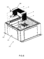
- Fig. 6 is an exploded view of the power plate assembly installed in the enclosure of Fig. 5 with a vented cover positioned to be installed over the power plate assembly.
- Fig. 7 is a top perspective view of the power plate assembly and vented cover of Fig. 6 installed in the enclosure.
- Fig. 8 is a front perspective view of the power plate assembly of Fig. 5 with power entry through the gland plate.
- Fig. 9 is a back perspective view of the power plate assembly of FIG. 8 with the vented cover installed on the power plate assembly.
- Fig. 10 is a front view of an alternative enclosure for electrical equipment with a front cover removed.
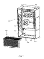
- Fig. 11 is a front exploded perspective view of the enclosure of Fig. 10 with an alternative vented cover positioned to be installed in the enclosure.
- Fig. 12 is a perspective view of the alternative vented cover of Fig. 11 .
- Fig. 13 is a side view of the enclosure with the alternative vented cover of Fig. 11 installed over the power plate assembly.
- Fig. 1 illustrates an enclosure for electrical equipment 20 with the front cover of the enclosure removed.
- the left side 22 of the enclosure 20 includes a gland plate 32 with a DIN rail 44 mounted to a DIN rail standoff plate 38 (see Fig. 3 ) which can be pre-wired as a sub-assembly prior to installation in the enclosure 20.
- the enclosure 20 also includes power terminals, contacts, conductors or other components operating at less than 50 volts mounted to a DIN rail on the enclosure back plate 24. Although a DIN rail is utilized in this enclosure, other industrial standard mounting techniques are acceptable.
- This enclosure illustrates the gland plate 32 located on the left side of the enclosure; however, the gland plate could be located on other walls of the enclosure.
- Fig. 2 illustrates elements of the power plate assembly 30 that is installed in the side 22 of the enclosure 20 of Fig. 1 .
- the power plate assembly 30 includes a gland plate 32 with a plurality of countersunk rivet holes 34 positioned near the edges, gasket strips 36 and a DIN rail standoff plate 38.
- the gasket strips 36 are applied to the outside perimeter of the gland plate 32.
- the gasket strips are 1 ⁇ 4 inch in height with the gland plate 32 having a flange with a height of 1 ⁇ 8 inch to limit the compression of the gasket to 50% when installed in the enclosure 20.
- the gasket strips 36 allow the power plate to create a dust and moisture resistant connection with the enclosure 20.
- the DIN rail standoff plate 38 is secured to the gland plate 32 via a plurality of flat head rivets 42 to form the power plate assembly 30.
- Fig. 3 illustrates the power plate assembly 30 with a DIN rail 44 cut to the desired length and positioned to be installed on the DIN rail standoff plate 38.
- the DIN rail standoff plate 38 has threaded studs 40 pressed in place to mount the DIN rail 44 with hex nuts 46 or other industry standard fasteners. Once the DIN rails 44 are secured to the DIN rail standoff plate 38, the components 48 may be installed.
- Fig.4 illustrates typical components 48 being installed on the DIN rail.
- a power supply 50, a surge or filter 52, a DC UPS 54 and a fuse 56 may be installed on the power plate assembly 30.
- the power plate assembly 30 utilized in this enclosure also includes an optional ground bar 58 for easier termination.
- the power plate assembly 30 may also include optional push-in place cable retaining clips 60 to route and protect wiring routing thereon.
- the power plate assembly 30 can be pre-wired before it is installed in the side 22 of the enclosure 20.
- Fig. 5 illustrates the power plate assembly 30 with the installed electrical components 48 positioned to be installed in the enclosure 20.
- the power plate assembly 30 is installed in the side 22 of the enclosure 20 with hex nuts or other industry standard fasteners. Once installed, the final wiring is completed within the enclosure.
- a vented or perforated cover 90 is installed over the power plate assembly 30 inside the enclosure 20.
- the vented cover includes openings or holes in at least one of the top and sides of the cover, as desired.
- the power wiring enters and exits the vented cover 90 through removable rubber grommets 92 positioned around the cover 90.
- the vented cover 90 is secured in place with tamper resistant fasteners to prevent removal by personnel who are not trained to access or maintain the power terminals, contacts, conductors or other components located within the power plate assembly.
- the vented cover 90 allows heat to dissipate from the components.
- the conductors operating at 50 volts or more within the enclosure and outside the vented cover are enclosed in a protective sheath to maintain the separation of these conductors from the area operating at less than 50 volts.
- Fig. 7 illustrates the power plate assembly 30 and vented cover 90 fully installed in the enclosure 20.
- the power terminals, contacts, conductors or other components operating at 50 volts or more are separated from power terminals, contacts, conductors, or other components operating at less than 50 volts. Therefore per industry standards, the shock hazard of the power terminals, contacts, conductors or other components operating at less than 50 volts is mitigated.
- Fig. 7 also illustrates an optional LED door switch 100 that will be wired to the covered power supplies through the grommets in the vented cover. This optional LED door switch operates at less than 50 volts.
- Figs. 8 and 9 illustrate the power plate assembly 30 and the vented cover 90 of the present invention.
- Conductors operating at 50 volts or more can be connected to the outside of the power plate assembly to allow the power entry 94 through the gland plate 32 and under the vented cover plate 90.
- the vented cover plate 90 completely covers the incoming conductors operating at 50 volts or more.
- Figs. 10-13 illustrate an alternative enclosure 120 with a power plate assembly 30 and vented or perforated cover 190.
- Fig. 10 illustrates a pre-configured enclosure. All of the power terminals 150, contacts, conductors or other components operating at 50 volts or more are mounted on the enclosure back plate 122 at the bottom 124 of the enclosure 120 to allow a single vented cover 190 to be installed over the components. The components outside of the covered area operate at less than 50 volts.
- Fig. 11 illustrates the enclosure 120 with a vented cover 190 positioned to be installed over the removable gland plate 132 and the power terminals 150, contacts, conductors or other components operating at 50 volts or more that are mounted to the DIN rail 144 (see Fig. 10 ) on the enclosure mounted to back plate 122.
- the vented cover 190 will be fastened in place with tamper resistance fasteners.
- incoming conductors operating at 50 volts or more 210 are brought into the zone enclosure 120 through a fitting installed on the gland plate 132.
- the power terminals, contacts, conductors or other components operating at 50 volts or more are separated from power terminals, contacts, conductors, or other components operating at less than 50 volts. Therefore per industry standards, the shock hazard of the power terminals, contacts, conductors or other components operating at less than 50 volts is mitigated.
- Fig. 12 illustrates the vented cover 190.
- the vented cover 190 allows heat generated from the power terminals 150, contacts, conductors or other components operating at 50 volts or more to dissipate. As discussed above, the vented cover 190 also separates the power terminals, contacts, conductors or other components operating at 50 volts or more from power terminals, contacts, conductors, or other components operating at less than 50 volts.
- the vented cover 190 can include grommets.
- Grommet 192 for entry of power for terminals, contacts, conductors or other components operating at 50 volts or more (if the power entry is not through the gland plate 132) and a grommet 194 for an exit of power terminals, contacts, conductors, or other components operating at less than 50 volts can be located at various places on the cover.
- the vented cover 190 also includes a back flange 196 to attach to the enclosure bottom gland plate threaded studs, flanged edges 198 for rigidity, and a bottom flange 200 to attach to the enclosure back plate 122. Furthermore, the conductors operating at 50 volts or more within the enclosure and outside the vented cover are enclosed in a protective sheath to maintain the separation of these conductors from the area operating at less than 50 volts.
- Fig. 13 illustrates a cross section of the enclosure 120 with the vented cover 190 positioned over the power terminals 150, contacts, conductors or other components operating at 50 volts or more.
- the vented cover is mounted on the back plate 122 and secured to the gland plate 132 via a threaded stud.
- this enclosure illustrates the vented cover, gland plate and the power terminals, contacts, conductors or other components operating at 50 volts or more located at the bottom of the enclosure, these components could be located on different faces of the enclosure.
- the enclosure for electrical equipment power plate assembly of the present invention provides protection against accidental contact with power terminals, contacts or conductors operating at 50 volts or more by personnel who are not trained to access or maintain these terminals, contacts or conductors by totally enclosing these components under a tamper resistant cover.
- the power plate assembly completely encloses incoming wiring operating at 50 volts or more by providing a location for the incoming conductor entry into the gland plate of the power plate assembly.
- the power plate assembly provides the ability to access the enclosure without removing power to the terminals, contacts or conductors operating at less than 50 volts and maximizes the available space on the enclosure back plate for equipment by moving the components operating at 50 volts or more to the side or bottom of the enclosure.
- the power plate assembly and the vented cover of the present invention segregate and cover power terminals, contacts or conductors operating at 50 volts or more form personnel who are not trained to access or maintain these terminals, contacts or conductors while maximizing the available space on the enclosure back plate.
Landscapes
- Engineering & Computer Science (AREA)
- Power Engineering (AREA)
- Aviation & Aerospace Engineering (AREA)
- Physics & Mathematics (AREA)
- Thermal Sciences (AREA)
- Microelectronics & Electronic Packaging (AREA)
- Casings For Electric Apparatus (AREA)
- Connections Arranged To Contact A Plurality Of Conductors (AREA)
Abstract
Description
- This application claims priority to
U.S. Provisional Application No. 61/539,211, filed September 26, 2011 - The present invention relates to enclosing power components in an enclosure for electrical equipment, and more particularly to a vented cover for enclosing power components in an enclosure for electrical equipment.
- Power terminals, contacts, conductors or other components operating at 50 volts or more in an enclosure need to be segregated and covered to ensure that personnel who are not trained do not have access to these terminals, contacts, conductors or other components. Generally, the power is turned off during maintenance of the components located in the enclosure. It would be desirable to eliminate the need to turn off the power to the enclosure by providing a method of segregating and covering the power terminals, contacts, conductors or other components operating at 50 volts or more in the enclosure. Therefore, allowing personnel who are trained to have access to the power terminals, contacts, conductors or other devices operating at less than 50 volts. It would also be desirable to maximize the amount of space available for mounting these power terminals, contacts, conductors or other components in the enclosure.
- The present invention is directed to an enclosure for electrical equipment. The enclosure includes a power plate assembly and a vented cover installed over the power plate assembly. The power plate assembly includes a gland plate, gasket strips surrounding the gland plate for creating a moisture resistant connection with the enclosure and a standoff plate secured to the gland plate. Electrical components operating at 50 or more volts are secured to the power plate assembly. Since the vented cover is installed over the power plate assembly, the vented cover separates the electrical components in the enclosure that operate at 50 volts or more from electrical components installed in the enclosure that operate at less than 50 volts.
-
Fig. 1 is a front view of an enclosure for electrical equipment with a front cover removed. -
Fig. 2 is an exploded view of a power plate assembly to be installed in the enclosure ofFig. 1 . -
Fig. 3 is a front exploded view of the power plate assembly ofFIG. 2 with a DIN rail positioned to be installed. -
Fig. 4 is front exploded view of the power plate assembly ofFIG. 3 with electrical components positioned to be installed. -
Fig. 5 is an exploded view of the power plate assembly ofFig. 4 positioned to be installed in the enclosure. -
Fig. 6 is an exploded view of the power plate assembly installed in the enclosure ofFig. 5 with a vented cover positioned to be installed over the power plate assembly. -
Fig. 7 is a top perspective view of the power plate assembly and vented cover ofFig. 6 installed in the enclosure. -
Fig. 8 is a front perspective view of the power plate assembly ofFig. 5 with power entry through the gland plate. -
Fig. 9 is a back perspective view of the power plate assembly ofFIG. 8 with the vented cover installed on the power plate assembly. -
Fig. 10 is a front view of an alternative enclosure for electrical equipment with a front cover removed. -
Fig. 11 is a front exploded perspective view of the enclosure ofFig. 10 with an alternative vented cover positioned to be installed in the enclosure. -
Fig. 12 is a perspective view of the alternative vented cover ofFig. 11 . -
Fig. 13 is a side view of the enclosure with the alternative vented cover ofFig. 11 installed over the power plate assembly. -
Fig. 1 illustrates an enclosure forelectrical equipment 20 with the front cover of the enclosure removed. Theleft side 22 of theenclosure 20 includes agland plate 32 with aDIN rail 44 mounted to a DIN rail standoff plate 38 (seeFig. 3 ) which can be pre-wired as a sub-assembly prior to installation in theenclosure 20. Theenclosure 20 also includes power terminals, contacts, conductors or other components operating at less than 50 volts mounted to a DIN rail on theenclosure back plate 24. Although a DIN rail is utilized in this enclosure, other industrial standard mounting techniques are acceptable. This enclosure illustrates thegland plate 32 located on the left side of the enclosure; however, the gland plate could be located on other walls of the enclosure. -
Fig. 2 illustrates elements of thepower plate assembly 30 that is installed in theside 22 of theenclosure 20 ofFig. 1 . Thepower plate assembly 30 includes agland plate 32 with a plurality ofcountersunk rivet holes 34 positioned near the edges,gasket strips 36 and a DINrail standoff plate 38. Thegasket strips 36 are applied to the outside perimeter of thegland plate 32. The gasket strips are ¼ inch in height with thegland plate 32 having a flange with a height of ⅛ inch to limit the compression of the gasket to 50% when installed in theenclosure 20. Thegasket strips 36 allow the power plate to create a dust and moisture resistant connection with theenclosure 20. The DINrail standoff plate 38 is secured to thegland plate 32 via a plurality of flat head rivets 42 to form thepower plate assembly 30. -
Fig. 3 illustrates thepower plate assembly 30 with aDIN rail 44 cut to the desired length and positioned to be installed on the DINrail standoff plate 38. The DINrail standoff plate 38 has threadedstuds 40 pressed in place to mount theDIN rail 44 withhex nuts 46 or other industry standard fasteners. Once theDIN rails 44 are secured to the DINrail standoff plate 38, thecomponents 48 may be installed. -
Fig.4 illustratestypical components 48 being installed on the DIN rail. For example, apower supply 50, a surge orfilter 52, a DC UPS 54 and afuse 56 may be installed on thepower plate assembly 30. Thepower plate assembly 30 utilized in this enclosure also includes anoptional ground bar 58 for easier termination. Thepower plate assembly 30 may also include optional push-in placecable retaining clips 60 to route and protect wiring routing thereon. Thepower plate assembly 30 can be pre-wired before it is installed in theside 22 of theenclosure 20. -
Fig. 5 illustrates thepower plate assembly 30 with the installedelectrical components 48 positioned to be installed in theenclosure 20. Thepower plate assembly 30 is installed in theside 22 of theenclosure 20 with hex nuts or other industry standard fasteners. Once installed, the final wiring is completed within the enclosure. Next, as illustrated inFig. 6 , a vented or perforatedcover 90 is installed over thepower plate assembly 30 inside theenclosure 20. The vented cover includes openings or holes in at least one of the top and sides of the cover, as desired. The power wiring enters and exits the ventedcover 90 throughremovable rubber grommets 92 positioned around thecover 90. The ventedcover 90 is secured in place with tamper resistant fasteners to prevent removal by personnel who are not trained to access or maintain the power terminals, contacts, conductors or other components located within the power plate assembly. The ventedcover 90 allows heat to dissipate from the components. Furthermore, the conductors operating at 50 volts or more within the enclosure and outside the vented cover are enclosed in a protective sheath to maintain the separation of these conductors from the area operating at less than 50 volts. -
Fig. 7 illustrates thepower plate assembly 30 and ventedcover 90 fully installed in theenclosure 20. As a result, the power terminals, contacts, conductors or other components operating at 50 volts or more are separated from power terminals, contacts, conductors, or other components operating at less than 50 volts. Therefore per industry standards, the shock hazard of the power terminals, contacts, conductors or other components operating at less than 50 volts is mitigated. Furthermore,Fig. 7 also illustrates an optionalLED door switch 100 that will be wired to the covered power supplies through the grommets in the vented cover. This optional LED door switch operates at less than 50 volts. -
Figs. 8 and9 illustrate thepower plate assembly 30 and the ventedcover 90 of the present invention. Conductors operating at 50 volts or more can be connected to the outside of the power plate assembly to allow thepower entry 94 through thegland plate 32 and under the ventedcover plate 90. Thus, the ventedcover plate 90 completely covers the incoming conductors operating at 50 volts or more. -
Figs. 10-13 illustrate analternative enclosure 120 with apower plate assembly 30 and vented orperforated cover 190.Fig. 10 illustrates a pre-configured enclosure. All of thepower terminals 150, contacts, conductors or other components operating at 50 volts or more are mounted on the enclosure backplate 122 at the bottom 124 of theenclosure 120 to allow a single ventedcover 190 to be installed over the components. The components outside of the covered area operate at less than 50 volts. -
Fig. 11 illustrates theenclosure 120 with a ventedcover 190 positioned to be installed over theremovable gland plate 132 and thepower terminals 150, contacts, conductors or other components operating at 50 volts or more that are mounted to the DIN rail 144 (seeFig. 10 ) on the enclosure mounted to backplate 122. The ventedcover 190 will be fastened in place with tamper resistance fasteners. As illustrated, incoming conductors operating at 50 volts or more 210 are brought into thezone enclosure 120 through a fitting installed on thegland plate 132. As a result, the power terminals, contacts, conductors or other components operating at 50 volts or more are separated from power terminals, contacts, conductors, or other components operating at less than 50 volts. Therefore per industry standards, the shock hazard of the power terminals, contacts, conductors or other components operating at less than 50 volts is mitigated. -
Fig. 12 illustrates the ventedcover 190. The ventedcover 190 allows heat generated from thepower terminals 150, contacts, conductors or other components operating at 50 volts or more to dissipate. As discussed above, the ventedcover 190 also separates the power terminals, contacts, conductors or other components operating at 50 volts or more from power terminals, contacts, conductors, or other components operating at less than 50 volts. The ventedcover 190 can include grommets.Grommet 192 for entry of power for terminals, contacts, conductors or other components operating at 50 volts or more (if the power entry is not through the gland plate 132) and agrommet 194 for an exit of power terminals, contacts, conductors, or other components operating at less than 50 volts can be located at various places on the cover. The ventedcover 190 also includes aback flange 196 to attach to the enclosure bottom gland plate threaded studs,flanged edges 198 for rigidity, and abottom flange 200 to attach to the enclosure backplate 122. Furthermore, the conductors operating at 50 volts or more within the enclosure and outside the vented cover are enclosed in a protective sheath to maintain the separation of these conductors from the area operating at less than 50 volts. -
Fig. 13 illustrates a cross section of theenclosure 120 with the ventedcover 190 positioned over thepower terminals 150, contacts, conductors or other components operating at 50 volts or more. The vented cover is mounted on theback plate 122 and secured to thegland plate 132 via a threaded stud. Although this enclosure illustrates the vented cover, gland plate and the power terminals, contacts, conductors or other components operating at 50 volts or more located at the bottom of the enclosure, these components could be located on different faces of the enclosure. - The enclosure for electrical equipment power plate assembly of the present invention provides protection against accidental contact with power terminals, contacts or conductors operating at 50 volts or more by personnel who are not trained to access or maintain these terminals, contacts or conductors by totally enclosing these components under a tamper resistant cover. The power plate assembly completely encloses incoming wiring operating at 50 volts or more by providing a location for the incoming conductor entry into the gland plate of the power plate assembly. The power plate assembly provides the ability to access the enclosure without removing power to the terminals, contacts or conductors operating at less than 50 volts and maximizes the available space on the enclosure back plate for equipment by moving the components operating at 50 volts or more to the side or bottom of the enclosure. Thus, the power plate assembly and the vented cover of the present invention segregate and cover power terminals, contacts or conductors operating at 50 volts or more form personnel who are not trained to access or maintain these terminals, contacts or conductors while maximizing the available space on the enclosure back plate.
- Furthermore while the particular preferred embodiments of the present invention have been shown and described, it will be obvious to those skilled in the art that changes and modifications may be made without departing from the teaching of the invention. The matter set forth in the foregoing description and accompanying drawings is offered by way of illustration only and not as limitation.
- The invention may furthermore be embodied according to the following numbered clauses:
- 1. An enclosure for electrical equipment, the enclosure comprising:
- a back plate,
- a plurality of electrical components operating at 50 volts or more mounted on the back plate;
- a gland plate installed in a bottom of the enclosure;
- a vented cover installed over the gland plate and the plurality of components operating at 50 volts or more; and
- a plurality of electrical components operating at less than 50 volts installed in the enclosure;
- whereby the vented cover maintains the separation of the electrical components operating at 50 volts or more and the electrical components operating at less than 50 volts.
- 2. The enclosure of clause 1, wherein the vented cover includes a grommet for enabling power wiring to be routed therein.
- 3. The enclosure of clause 1, wherein the vented cover having a back flange to attach the vented cover to the gland plate and a bottom flange to attach the vented cover to the back plate of the enclosure.
- 4. The enclosure of clause 1, wherein the vented cover having flanged edges along at least one side of the vented cover for providing rigidity to the vented cover.
Claims (7)
- An enclosure for electrical equipment, the enclosure comprising:a power plate assembly including a gland plate, gasket strips surrounding the gland plate for creating a moisture resistant connection with the enclosure, and a standoff plate secured to the gland plate; anda vented cover installed over the power plate assembly inside the enclosure.
- The enclosure of claim 1, wherein the power plate assembly is installed in a side of the enclosure.
- The enclosure of claim 1, wherein the standoff plate further comprising a rail and electrical components mounted to the rail.
- The enclosure of claim 3, wherein the electrical components mounted to the rail operate at 50 volts or more; and wherein the vented cover separates the electrical components mounted to the rail from electrical components mounted in the enclosure that operate at less than 50 volts.
- The enclosure of claim 1, wherein the vented cover comprising rubber grommets for enabling power wiring to be routed therein.
- The enclosure of claim 1, wherein the vented cover is secured via tamper resistant fasteners to prevent removal of the vented cover and electrical components installed on the power plate assembly.
- The enclosure of claim 1, wherein the vented cover enables heat to dissipate from electrical components installed on the power plate assembly.
Applications Claiming Priority (3)
| Application Number | Priority Date | Filing Date | Title |
|---|---|---|---|
| US201161539211P | 2011-09-26 | 2011-09-26 | |
| US13/622,778 US8941977B2 (en) | 2011-09-26 | 2012-09-19 | Power safety assembly |
| EP12186058.9A EP2573886B1 (en) | 2011-09-26 | 2012-09-26 | Power plate assembly with vented safety cover |
Related Parent Applications (2)
| Application Number | Title | Priority Date | Filing Date |
|---|---|---|---|
| EP12186058.9A Division-Into EP2573886B1 (en) | 2011-09-26 | 2012-09-26 | Power plate assembly with vented safety cover |
| EP12186058.9A Division EP2573886B1 (en) | 2011-09-26 | 2012-09-26 | Power plate assembly with vented safety cover |
Publications (1)
| Publication Number | Publication Date |
|---|---|
| EP2688162A1 true EP2688162A1 (en) | 2014-01-22 |
Family
ID=47278647
Family Applications (2)
| Application Number | Title | Priority Date | Filing Date |
|---|---|---|---|
| EP12186058.9A Not-in-force EP2573886B1 (en) | 2011-09-26 | 2012-09-26 | Power plate assembly with vented safety cover |
| EP13189330.7A Withdrawn EP2688162A1 (en) | 2011-09-26 | 2012-09-26 | Power plate assembly with vented safety cover |
Family Applications Before (1)
| Application Number | Title | Priority Date | Filing Date |
|---|---|---|---|
| EP12186058.9A Not-in-force EP2573886B1 (en) | 2011-09-26 | 2012-09-26 | Power plate assembly with vented safety cover |
Country Status (2)
| Country | Link |
|---|---|
| US (2) | US8941977B2 (en) |
| EP (2) | EP2573886B1 (en) |
Families Citing this family (5)
| Publication number | Priority date | Publication date | Assignee | Title |
|---|---|---|---|---|
| US9615470B2 (en) * | 2012-10-03 | 2017-04-04 | Sunlink Corporation | Wiring combiner box |
| EP3358687B1 (en) * | 2017-02-01 | 2023-08-30 | Hager Electro GmbH & Co. KG | Partitioning device for a distribution cabinet and distribution cabinet comprising such a partitioning device |
| DE102017110596A1 (en) * | 2017-05-16 | 2018-11-22 | Hager Electro Gmbh & Co. Kg | FASTENING DEVICE, DOOR FOR A CONTROL CABINET AND A CONTROL CABIN COMPRISING ONE SUCH DOOR |
| US11095117B2 (en) * | 2018-07-20 | 2021-08-17 | Vertiv Corporation | DC-DC converters having DIN rail mounts |
| CN111786278A (en) * | 2020-07-16 | 2020-10-16 | 安徽卓越电力设备有限公司 | Low-voltage power distribution cabinet device for preventing electric shock |
Citations (2)
| Publication number | Priority date | Publication date | Assignee | Title |
|---|---|---|---|---|
| US6373688B1 (en) * | 2001-07-12 | 2002-04-16 | General Electric Company | Service entrance barrier insulator |
| FR2957198A1 (en) * | 2010-03-02 | 2011-09-09 | Hager Controls | Electrical box, has low voltage electric module fixed to metal frame, where low voltage electric module is fixed to rest of electrical box by mechanical retaining unit inaccessible from user zone |
Family Cites Families (22)
| Publication number | Priority date | Publication date | Assignee | Title |
|---|---|---|---|---|
| US3354435A (en) * | 1965-02-19 | 1967-11-21 | Ibm | Transmission line control of transistor selection matrix |
| US5046173A (en) * | 1990-10-18 | 1991-09-03 | General Electric Company | Single branch circuit breaker support |
| CA2064639C (en) * | 1992-04-01 | 1995-04-18 | Michael Ray Harris | Terminal barrier for electrical load centers |
| DE19804904C1 (en) | 1998-02-07 | 1999-11-11 | Loh Kg Rittal Werk | Control cabinet with facilities for cooling the interior warm air |
| US6015197A (en) * | 1998-02-28 | 2000-01-18 | 3Com Corp. | Protective grommet apparatus and method |
| US6456203B1 (en) * | 2000-04-03 | 2002-09-24 | Adc Telecommunications, Inc. | Power distribution panel with modular elements |
| US6262880B1 (en) * | 2000-04-05 | 2001-07-17 | Eaton Corporation | Circuit breaker mounting assembly with moveable remote terminal block |
| US7718889B2 (en) * | 2001-03-20 | 2010-05-18 | American Power Conversion Corporation | Adjustable scalable rack power system and method |
| US6772246B2 (en) | 2001-07-23 | 2004-08-03 | Sun Microsystems, Inc. | PCI riser card bracket assembly |
| US6731507B2 (en) * | 2001-09-26 | 2004-05-04 | Hewlett-Packard Development Company, L.P. | Modular AC input section for a power supply unit |
| US6668565B1 (en) * | 2002-04-12 | 2003-12-30 | American Power Conversion | Rack-mounted equipment cooling |
| US7149546B1 (en) | 2002-08-28 | 2006-12-12 | Sprint Spectrum L.P. | Subterranean equipment bay |
| US7035115B2 (en) * | 2003-04-11 | 2006-04-25 | Rockwell Automation Technologies, Inc. | Multi-axis motor control with high voltage backplane |
| US7108051B2 (en) | 2004-05-17 | 2006-09-19 | Kuo-Chuan Hung | CPU heat dissipating unit |
| CA2510529C (en) | 2005-06-20 | 2013-08-27 | Vertiv Corporation | Electromagnet-assisted ventilation cover for an electronic equipment enclosure |
| US7794312B2 (en) | 2005-10-07 | 2010-09-14 | Lennox Industries, Inc. | Enclosure cover and method for making an enclosure cover |
| US7209360B1 (en) | 2005-10-28 | 2007-04-24 | Lear Corporation | Leak-tight system for boxes containing electrical and electronic components |
| US7432441B2 (en) | 2006-02-14 | 2008-10-07 | Super Micro Computer, Inc. | Assembly of modularized housing and door cover |
| FR2934906B1 (en) | 2008-08-05 | 2010-09-03 | Thales Sa | ON-BOARD CALCULATOR EQUIPPED WITH AN AUTONOMOUS AERAULIC COOLING DEVICE |
| US7898787B2 (en) * | 2008-10-09 | 2011-03-01 | Adc Telecommunications, Inc. | Power panel with angled connectors |
| US8003899B2 (en) | 2008-11-25 | 2011-08-23 | Mettler-Toledo, Inc. | Mounting for industrial instrumentation |
| JP5510750B2 (en) * | 2011-04-18 | 2014-06-04 | 株式会社安川電機 | Power converter and reactor |
-
2012
- 2012-09-19 US US13/622,778 patent/US8941977B2/en active Active
- 2012-09-26 EP EP12186058.9A patent/EP2573886B1/en not_active Not-in-force
- 2012-09-26 EP EP13189330.7A patent/EP2688162A1/en not_active Withdrawn
-
2014
- 2014-12-11 US US14/567,715 patent/US8982540B1/en not_active Expired - Fee Related
Patent Citations (2)
| Publication number | Priority date | Publication date | Assignee | Title |
|---|---|---|---|---|
| US6373688B1 (en) * | 2001-07-12 | 2002-04-16 | General Electric Company | Service entrance barrier insulator |
| FR2957198A1 (en) * | 2010-03-02 | 2011-09-09 | Hager Controls | Electrical box, has low voltage electric module fixed to metal frame, where low voltage electric module is fixed to rest of electrical box by mechanical retaining unit inaccessible from user zone |
Also Published As
| Publication number | Publication date |
|---|---|
| US8982540B1 (en) | 2015-03-17 |
| EP2573886A1 (en) | 2013-03-27 |
| EP2573886B1 (en) | 2014-09-10 |
| US20130077258A1 (en) | 2013-03-28 |
| US8941977B2 (en) | 2015-01-27 |
Similar Documents
| Publication | Publication Date | Title |
|---|---|---|
| US8982540B1 (en) | Power safety assembly | |
| US7719835B1 (en) | Wiring distribution device for an electronics rack | |
| US8697993B2 (en) | Hinged busway | |
| US9257824B2 (en) | Electrical enclosure with improved mechanical arrangement | |
| US20020157846A1 (en) | Remote distribution cabinet | |
| EP3483994A1 (en) | Isolation and exhaust system for an electrical enclosure | |
| KR100896926B1 (en) | Motor control board | |
| US20100120286A1 (en) | Power Panel with Angled Connectors | |
| US20150214700A1 (en) | Ac circuit breaker panels and telecommunications equipment cabinets having ac circuit breaker panels | |
| JP2009136142A (en) | Formation vehicle and high voltage circuit breaker thereof | |
| US3967165A (en) | Switchboard apparatus having control wiring passageways | |
| US9667041B2 (en) | Electrically insulating cover for terminal assembly | |
| CN109673130B (en) | Electrical unit with improved ventilation protection for a motor control center | |
| DE102017001929A1 (en) | Electronic module for an electric motor, in particular a pump set | |
| KR101646088B1 (en) | Busbars having different cross sections for a busbar system with a common protection or neutral conductor | |
| KR101371679B1 (en) | transparent distribution box | |
| US9532477B2 (en) | Data rack support and wire management system and methods for using the same | |
| JP4566136B2 (en) | Switchgear | |
| CN203826798U (en) | Fastening and separating components for switchgear | |
| KR101445110B1 (en) | Distribution power box with insulation cover | |
| JP5283840B2 (en) | Branch unit and bus duct system | |
| KR102822894B1 (en) | A smart type terminal assembly for electric power distribution | |
| KR102884732B1 (en) | Distribution board | |
| US5831812A (en) | Meter center tap duct | |
| CN102882134A (en) | Vertical busbar protective device for low voltage switch box |
Legal Events
| Date | Code | Title | Description |
|---|---|---|---|
| PUAI | Public reference made under article 153(3) epc to a published international application that has entered the european phase |
Free format text: ORIGINAL CODE: 0009012 |
|
| AC | Divisional application: reference to earlier application |
Ref document number: 2573886 Country of ref document: EP Kind code of ref document: P |
|
| AK | Designated contracting states |
Kind code of ref document: A1 Designated state(s): AL AT BE BG CH CY CZ DE DK EE ES FI FR GB GR HR HU IE IS IT LI LT LU LV MC MK MT NL NO PL PT RO RS SE SI SK SM TR |
|
| AX | Request for extension of the european patent |
Extension state: BA ME |
|
| 17P | Request for examination filed |
Effective date: 20140715 |
|
| RBV | Designated contracting states (corrected) |
Designated state(s): AL AT BE BG CH CY CZ DE DK EE ES FI FR GB GR HR HU IE IS IT LI LT LU LV MC MK MT NL NO PL PT RO RS SE SI SK SM TR |
|
| STAA | Information on the status of an ep patent application or granted ep patent |
Free format text: STATUS: THE APPLICATION HAS BEEN WITHDRAWN |
|
| 18W | Application withdrawn |
Effective date: 20141216 |