EP2688021A2 - Method for identifying the maximal packing density of shifting-tiles automated warehouses - Google Patents
Method for identifying the maximal packing density of shifting-tiles automated warehouses Download PDFInfo
- Publication number
- EP2688021A2 EP2688021A2 EP13153522.1A EP13153522A EP2688021A2 EP 2688021 A2 EP2688021 A2 EP 2688021A2 EP 13153522 A EP13153522 A EP 13153522A EP 2688021 A2 EP2688021 A2 EP 2688021A2
- Authority
- EP
- European Patent Office
- Prior art keywords
- layout
- warehouse
- cells
- cell
- blank
- Prior art date
- Legal status (The legal status is an assumption and is not a legal conclusion. Google has not performed a legal analysis and makes no representation as to the accuracy of the status listed.)
- Withdrawn
Links
Images


Classifications
-
- G—PHYSICS
- G06—COMPUTING OR CALCULATING; COUNTING
- G06Q—INFORMATION AND COMMUNICATION TECHNOLOGY [ICT] SPECIALLY ADAPTED FOR ADMINISTRATIVE, COMMERCIAL, FINANCIAL, MANAGERIAL OR SUPERVISORY PURPOSES; SYSTEMS OR METHODS SPECIALLY ADAPTED FOR ADMINISTRATIVE, COMMERCIAL, FINANCIAL, MANAGERIAL OR SUPERVISORY PURPOSES, NOT OTHERWISE PROVIDED FOR
- G06Q10/00—Administration; Management
- G06Q10/04—Forecasting or optimisation specially adapted for administrative or management purposes, e.g. linear programming or "cutting stock problem"
-
- G—PHYSICS
- G06—COMPUTING OR CALCULATING; COUNTING
- G06Q—INFORMATION AND COMMUNICATION TECHNOLOGY [ICT] SPECIALLY ADAPTED FOR ADMINISTRATIVE, COMMERCIAL, FINANCIAL, MANAGERIAL OR SUPERVISORY PURPOSES; SYSTEMS OR METHODS SPECIALLY ADAPTED FOR ADMINISTRATIVE, COMMERCIAL, FINANCIAL, MANAGERIAL OR SUPERVISORY PURPOSES, NOT OTHERWISE PROVIDED FOR
- G06Q10/00—Administration; Management
- G06Q10/08—Logistics, e.g. warehousing, loading or distribution; Inventory or stock management
- G06Q10/087—Inventory or stock management, e.g. order filling, procurement or balancing against orders
Definitions
- the present exemplary embodiment relates generally to warehouse management systems. It finds particular application in conjunction with identifying the maximal packing density in shifting-tiles automated warehouse and will be described with particular reference thereto. However, it is to be understood that it also finds application in other usage scenarios and is not necessarily limited to the aforementioned application.
- the warehouse utilizes shifting-tile floors where each floor consists of a two-dimensional grid of cells, each of which can hold a pallet and can move it to any adjacent cell unless there is a wall between them.
- the warehouse also includes an elevator located in at least one of the cells connecting the floor with both the loading/unloading port of the warehouse and other floors.
- Such a design only requires minimal space for the elevator. For instance, on a floor layout with 400 cells and only one elevator, only 1/400th of the space is required for the elevator, increasing the packing density of the warehouse by almost 50% compared to the current best practice.
- an automated warehouse including a grid of floor tiles can store and move pallets in a north-south direction and east-west direction. This allows the automated warehouse to achieve a higher packing density.
- the warehouse needs to be analyzed to determine how densely the pallets can be packed while still ensuring that every pallet can be retrieved. This is made more complicated by the existence of additional constraints, such as walls blocking some movements.
- a number of pallets need to be moved around so that the target pallet can reach the elevator. Once there, the pallet can be moved to the loading/unloading port of the warehouse. Whether or not a specific pallet can be moved to the elevator or not depends on 1) the layout of the floor in terms of walls blocking pallets from moving between certain adjacent cells and 2) the number of blank cells on the floor. For instance, if all the cells on a floor are occupied by pallets, only the pallet that is currently on the elevator can be retrieved. As such, a need exists to determine an optimal shifting-tiles floor layout which enables all of the pallets to be retrieved.
- the present disclosure provides a new and improved system and method which overcome the above-referenced problems and others.
- a method for determining a maximum packing density of an automated warehouse includes determining a layout of the automated warehouse, the layout including a plurality of cells, analyzing the layout of the automated warehouse utilizing an automated process to identify the maximum packing density of the layout, and displaying the maximum packing density of the layout.
- a warehouse management system including a layout module which determines a layout of the automated warehouse, the layout including at least one occupied cell and at least one blank cell and an analysis module which analyzes the layout of the automated warehouse to determine a minimum number of blank cells required to retrieve an object from all of the occupied cells in the warehouse.
- a warehouse management system includes a plurality of shifting-tile cells, the plurality of cells including at least one occupied cell, a layout module which determines a layout of the plurality of cells, and an analysis module which analyzes the layout of the plurality of cells to determine a minimum number of blank cells required to retrieve an object from all of the at least one occupied cell in the warehouse.
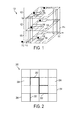
- FIGURE 1 is a graphical illustration of a shifting-tiles automated warehouse according to aspects of the present disclosure
- FIGURE 2 is an exemplary illustration of a floor plan of a shifting-tiles automated warehouse
- FIGURE 3 is a block diagram of a warehouse management system according to aspect of the present disclosure.
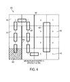
- FIGURE 4 is an exemplary illustration of an analyzed floor plan of a shifting-tiles automated warehouse
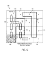
- FIGURE 5 is an exemplary illustration of an analyzed floor plan of a shifting-tiles automated warehouse including a buffer cell
- FIGURE 6 is a block diagram of a method for identifying the maximal packing density of a shifting-tiles automated warehouse according to aspect of the present disclosure.
- the exemplary embodiment provides a method for determining an optimal shifting-tiles floor layout in an automated warehouse which includes determining the minimal number of blanks cells required to retrieve all of the pallets in the warehouse.
- the advantage of this method is its efficiency and its accuracy of the number of blank cells required to retrieve all the pallets within the warehouse.
- the method ensures the determined number of blanks required for a given cell is indeed minimal and sufficient. For example, if the optimal shifting-tile floor layout requires the number of blanks to be K, then all of the pallets could be retrieved if K blank cells are available on the floor. As such, the method ensures that all pallets are retrievable while a certain packing density is not trespassed and optimal usage of warehouse capacity is achieved.
- a shifting-tiles automated warehouse 100 includes a plurality of floors 102 which each consist of a two-dimensional grid of cells 104. While only three floors are illustrated, more or less floors are contemplated. Each cell can stored and move pallets in each of the two-dimensional directions of the grid. Specifically, each of the floors 102 includes shifting-tiles which enable any occupied cell 106 to move a pallet to any adjacent blank cell 108 via conveyer belt and the like. Although a certain number of occupied and blank cells are illustrated, it should be appreciated that each of the floors includes more or less occupied cells and blanks cells. At least one of the cells of each floor includes at least one elevator connecting the floor with both the loading and unloading port of the warehouse and other floors.
- warehouse 100 includes two separate elevators, a loading elevator 110 which connects the floors with the loading port 112 of the warehouse 100 and an unloading elevator 114 which connects the floors with the unloading port 116 of the warehouse 100.
- the warehouse includes more or less elevators, and more or less loading and unloading ports.
- a single unloading/loading elevator connects the floors to a single unloading/loading port.
- a number of other pallets need to be moved such that the target pallet can reach the unloading elevator 114 and ultimately the unloading port 116 of the warehouse 110.
- the shifting-tile floor plans require a particular number of blank cells 108.
- determining whether a target pallet can be moved to the elevator depends on the layout of the floor in terms of walls blocking pallets from moving between certain adjacent cells and the number of blank cells on the floor.
- the floor plan 200 includes 16 total cells 204 in a four by four cell layout.
- the floor plan 200 also includes a plurality of internal walls 202 indicated by the bold lines in addition to a plurality of external walls 206 of the warehouse 100.
- shifting-tiles in each cell 104 enables any occupied cell to move a pallet to any adjacent blank cell unless there is a wall between them.
- the shifting tiles include conveyer belts, carousels, and the like.
- at least one of the cells includes an elevator to enable access to the other floors and the unloading/loading port of the warehouse.
- each floor includes more or less cells in various layouts, more or less internal walls, and more or less external walls.
- a warehouse management system 300 determines the optimal number of blank cells required to achieve the maximum packing density while ensuring that every pallet within the warehouse can be retrieved.
- the warehouse management system 300 includes a layout module 302 which generates or determines the layout of the floor or space of the warehouse including any obstruction or walls within the layout.
- the layout module 302 also generates or determines any loading or unloading locations including the locations of any elevators and/or loading and unloading ports of the warehouse.
- the layout module 302 may generate or determine the layout of the floor or space of the warehouse based on manual input and/or automatically. As to the former, the layout module 302 is associated with a user which controls the generation or determination of the layout.
- the warehouse management system typically each include or are associated with one or more user input devices 304, such as a keyboard, cursor, control device, touch screen, and so on and/or one or more user output devices 306, such as a display.
- layout module 302 includes software component stored in memory, and executed by a processor, which are pre-programmed to generate or determine the layout of the floor or space of the warehouse. After a layout has been generated or determined, the layout module 302 stores the layout in a layout memory 308 which is accessible by the warehouse management system 300.
- the warehouse system 300 also includes an analysis module 310 which analyzes the layout of the floor or space of the warehouse using an automated process to identify the maximal packing density for the layout.
- the analysis module 310 determines the optimal number of blank cells required to achieve the maximum packing density while ensuring that every pallet within the warehouse can be retrieved.
- the analysis module 310 re-computes for each cell the number of blanks required to retrieve a pallet for it.
- the analysis module 310 retrieves the current floor or space layout from the layout memory 308.
- the analysis module 310 may analyze the layout of the floor or space of the warehouse based on manual input and/or automatically.
- the analysis module 310 utilizes the one or more user input devices 304 and/or the one or more user output devices 306. As to the latter, the analysis utilizes an optimization algorithm and will be described in more detail below.
- the optimization algorithm determines the optimal number of blank cells required to achieve the maximum packing density while ensuring that every pallet can be retrieved based on the layout of the warehouse.
- the analysis module 310 includes software components stored in memory, and executed by a processor, which are pre-programmed to analyze the layout of the floor or space of the warehouse. After a layout has been analyzed, the analysis module 310 stores the results of the analysis in an analysis memory 312 which is accessible by the warehouse management system 300. It is also contemplated that the analysis module also displays the results of the analysis on the one or more user output devices 306.
- the warehouse management system 300, layout module 302, and the analysis module 310 further include a communication unit for communicating with the various modules connected to a communications network.
- a communication unit for communicating with the various modules connected to a communications network.
- One or more system buses link components of the management system 300, layout module 302, and the analysis module 310, such as the processor, the memory, and the communication unit.
- the management system 300, layout module 302, and the analysis module 310 may be resident, for example, on a server linked to via the communications network 28. However, in some embodiments, the layout module 302 and the analysis module 310 are integrated with management system 300.
- the analysis unit utilizes an optimization algorithm.
- the optimization algorithm is represented by the following algorithm respectively.
- Input a graph G, a distinguished node n* in G
- Output The number of blanks required in order to be able to move any object to n*.
- C ⁇ C1 ,... ,c m ⁇ of G using a well-known depth first search approach, starting at n *, where the components are ordered according to their LOW number; 2. Accordingly, c 1 is the component containing n *; 3. mark ( n* ) ⁇ (0,0) 4. foreach n' ⁇ c 1 such that n' is not marked do 5.
- mark ( n 1 ) (1,0) 6. Add c 1 to open list; 7. while open list not empty do 8. c ⁇ pop(openlist); 9. Remove c from C; 10. foreach c ' ⁇ C such that there is a node n such that n ⁇ c ' ⁇ c do 11. if
- mark ( n' ) l' 18. add c' to open list; 19. If there are any unmarked nodes, report them as inaccessible; 20. Outptut max n maxmark ( n ) , this is the number of required blanks; 21. Output the markings of all nodes;
- a graph G is defined by a set of nodes N and a set of edges E between them. Two nodes are called connected if there is an edge between them. A graph is called connected if there are no two nodes such that there is no path (sequence of edges) between them.
- adj (c) denotes the set of all nodes that are connected to c.
- a node n is a three-way node if
- a k-labeling for a graph G is a bijective function (a 1-to-1 mapping) L ( N ) ⁇ O ⁇ ⁇ 1 ,..., ⁇ k ⁇ where O is a set of object identifiers, and the ⁇ 's are blanks. As such,
- a labeling L can be moved to a labeling L' , denoted L L', if either:
- n 2 is adjacent to n 1 and contains the blank.
- n 1 and n are on a bi-connected component.
- n is in c ⁇ '+m+1 and a node n ⁇ that is shared by c i'+m and c i+m+1 exists.
- n ⁇ k ⁇ ⁇ 1 , k ⁇ ⁇ 2 .
- k 1 k ⁇ ⁇ 1 + 1.
- Object o can then be moved to n ⁇ if there is at least one blank in c i' + m +1 .
- object o can move from n to n * if and only if there are at least max(k 1 , k 2 ) blanks in the components c 1 , etc, c i .
- a graph G and a distinguished node n * in G are inputted into the optimization algorithm.
- the graph G describes the layout of the floor or space of the warehouse and is defined by a set of nodes N which denote the cell locations.
- the distinguished node n * represents the location of the elevator or the unloading port. From this information, the optimization algorithm determines the number of blank cells required to achieve the maximum packing density while ensuring that every pallet or object within the warehouse can be retrieved.
- the optimization algorithm begins by determining the bi-connected components c 1 ,..., c n of graph G. To determine the bi-connected components c 1 ,..., c n , the optimization algorithm utilizing a depth first search approach and the like which are well-known in the art.
- Bi-connected components exist whenever any two components are arranged with at least two paths connecting them.
- the bi-connected components c 1 ,... , c n are then ordered according to their LOW number generating a set of bi-connected components C.
- the LOW number corresponds to the distance from the component from the distinguished node n *.
- component c 1 is assigned the LOW number of one and is positioned in the location of the distinguished node n*.
- a components that is located four connects away from the distinguished node n* is assigned the LOW number of four.
- the optimization algorithm determines how many blank nodes are required to retrieve a pallet or object from each specific node n and transport it to distinguished node n*. For example, it is known that c 1 is located at distinguished node n * . As such, the optimization algorithm marks node c 1 representing the distance to the distinguished node n* and the number of blank nodes requires to retrieve a pallet or object from c 1 . The optimization algorithm then processes all neighboring or adjacent components and marks those components. This marking denotes the distance to the distinguished node and the minimum of one blank node required to move a pallet from that node to the distinguished node n*.
- the optimization algorithm then propagates this process for the rest of the nodes of the graph G until all of the components of the graph G have been marked. After processing all of the components, the optimization algorithm outputs the optimal packing density of graph G in terms of the required number of blanks required to retrieve a pallet from any specific node of graph G.
- the term "software”, as used herein, is intended to encompass any collection or set of instructions executable by a computer or other digital system so as to configure the computer or other digital system to perform the task that is the intent of the software.
- the term "software” as used herein is intended to encompass such instructions stored in storage medium such as RAM, a hard disk, optical disk, or so forth, and is also intended to encompass so called “firmware” that is software stored on a ROM or so forth.
- Such software may be organized in various ways, and may include software components organized as libraries, Internet based programs stored on a remote server or so forth, source code, interpretive code, object code, directly executable code, and so forth. It is contemplated that the software may invoke system level code or calls to other software residing on a server or other location to perform certain functions.
- module is intended to include a processor and a memory.
- user input device is intended to include one or more of a mouse, a keyboard, a touch screen display, one or more buttons, one or more switches, one or more toggles, and the like.
- user output device is intended to include one or more of a LCD display, an LED display, a plasma display, a projection display, a touch screen display, and the like.
- the term "communications network,” as used herein, is intended to include one or more of the Internet, a local area network, a wide area network, a wireless network, a wired network, a cellular network, a data bus, such as USB and I2C, and the like.
- the term "communication unit,” as used herein, is intended to include one or more of a modem, Ethernet adapter, WiFi adapter, 3G modem, a cable modem, a DSL modem, and any other adapter or modem facilitating communication with a network.
- processor is intended to include one or more of a microprocessor, a microcontroller, a graphic processing unit (GPU), an application-specific integrated circuit (ASIC), a field-programmable gate array (FPGA), and the like. Further, the above described processors, can each be variously embodied, such as by a single core processor, a dual core processor (or more generally by a multiple core processor), a digital processor and cooperating math coprocessor, a digital controller, or the like
- memory is intended to include one or more of a non-transient computer readable medium; a magnetic disk or other magnetic storage medium; an optical disk or other optical storage medium; a flash memory; a holographic memory; a random access memory (RAM), read-only memory (ROM), or other electronic memory device or chip or set of operatively interconnected chips; an Internet/Intranet server from which the stored instructions may be retrieved via the Internet/Intranet or a local area network; or so forth.
- each of the memories above described comprises a combination of random access memory and read only memory.
- Exemplary memory stores instructions for performing the exemplary method and data used and generated therein, as well operating instructions for operating the respective computer.
- the floor plan 400 includes 16 cells 402 and two internal walls 404.
- the elevator or unloading port of the floor plan is located in cell 406.
- the floor plan 400 also includes polygons 408 to indicate the bi-connected components between the cells 402.
- analysis module determines the required number of blank cells to retrieve a pallet from any particular cell.
- the floor plan includes markings 410 indicating the minimal number of required blanks to retrieve a pallet from each cell.
- an additional blank node is required. This is because the pallet being moved blocks the passage from the elevator to the blanks cells behind it. Once the passage opens up into a larger space, no more additional blanks are required.
- the floor plan 500 includes 16 cells 502 and two internal walls 504.
- the elevator or unloading port of the floor plan is located in cell 506.
- the floor plan 500 also includes polygons 508 to indicate the bi-connected components between the cells 502.
- the floor plan 500 also includes a buffer 510 which results in a three-way cell 512.
- analysis module determines the required number of blank cells to retrieve a pallet from any particular cell.
- the floor plan 500 markings 514 indicating the minimal number of required blanks to retrieve a pallet from each cell. Due to the buffer, the number of blank cells is reduced.
- the pallet In order to retrieve a pallet from cell 516, the pallet can first be moved into the buffer 510. Once there, its original cell can be used to store a pallet that is on route to the elevator, because the three way cell 512 is not blocked by the "to-be-retrieved" pallet itself.
- a block diagram of a method 600 for identifying the maximal packing density of an automated warehouse is illustrated.
- the layout or space including any constraints or obstructions and any in and out locations are generated or determined.
- the layout of the space or area is analyzed using an automated process to identify the maximal packing density for the space or area.
- an optimal packing density for the analyzed space or area is outputted.
Landscapes
- Business, Economics & Management (AREA)
- Engineering & Computer Science (AREA)
- Economics (AREA)
- Human Resources & Organizations (AREA)
- Strategic Management (AREA)
- Quality & Reliability (AREA)
- Physics & Mathematics (AREA)
- Entrepreneurship & Innovation (AREA)
- Marketing (AREA)
- Operations Research (AREA)
- Development Economics (AREA)
- Tourism & Hospitality (AREA)
- Theoretical Computer Science (AREA)
- General Business, Economics & Management (AREA)
- General Physics & Mathematics (AREA)
- Game Theory and Decision Science (AREA)
- Accounting & Taxation (AREA)
- Finance (AREA)
- Warehouses Or Storage Devices (AREA)
- Management, Administration, Business Operations System, And Electronic Commerce (AREA)
Abstract
Description
- The present exemplary embodiment relates generally to warehouse management systems. It finds particular application in conjunction with identifying the maximal packing density in shifting-tiles automated warehouse and will be described with particular reference thereto. However, it is to be understood that it also finds application in other usage scenarios and is not necessarily limited to the aforementioned application.
- Automated warehouses play an increasingly important role in logistics. The current best practice is to design such warehouses in a way where shelves are interleaved with shafts for cranes that can load and unload pallets from the shelves. While this makes controlling the warehouse relatively easy, it does not achieve a very high storage density as one third of the volume of the warehouse is typically required for the crane structure.
- One way to improve on this practice is with the addition of pallet moving facilities on the shelves themselves which allows for multi-layer storage of pallets on shelves (or floors). In such a design, the warehouse utilizes shifting-tile floors where each floor consists of a two-dimensional grid of cells, each of which can hold a pallet and can move it to any adjacent cell unless there is a wall between them. The warehouse also includes an elevator located in at least one of the cells connecting the floor with both the loading/unloading port of the warehouse and other floors. Such a design only requires minimal space for the elevator. For instance, on a floor layout with 400 cells and only one elevator, only 1/400th of the space is required for the elevator, increasing the packing density of the warehouse by almost 50% compared to the current best practice.
- For example, an automated warehouse including a grid of floor tiles can store and move pallets in a north-south direction and east-west direction. This allows the automated warehouse to achieve a higher packing density. However, to achieve this high packing density, the warehouse needs to be analyzed to determine how densely the pallets can be packed while still ensuring that every pallet can be retrieved. This is made more complicated by the existence of additional constraints, such as walls blocking some movements.
- In order to retrieve a pallet from such a warehouse, in most cases, a number of pallets need to be moved around so that the target pallet can reach the elevator. Once there, the pallet can be moved to the loading/unloading port of the warehouse. Whether or not a specific pallet can be moved to the elevator or not depends on 1) the layout of the floor in terms of walls blocking pallets from moving between certain adjacent cells and 2) the number of blank cells on the floor. For instance, if all the cells on a floor are occupied by pallets, only the pallet that is currently on the elevator can be retrieved. As such, a need exists to determine an optimal shifting-tiles floor layout which enables all of the pallets to be retrieved.
- The present disclosure provides a new and improved system and method which overcome the above-referenced problems and others.
- In accordance with one aspect of the present disclosure, a method for determining a maximum packing density of an automated warehouse is provided. The method includes determining a layout of the automated warehouse, the layout including a plurality of cells, analyzing the layout of the automated warehouse utilizing an automated process to identify the maximum packing density of the layout, and displaying the maximum packing density of the layout.
- In accordance with another aspect of the present disclosure, a warehouse management system is provided. The system including a layout module which determines a layout of the automated warehouse, the layout including at least one occupied cell and at least one blank cell and an analysis module which analyzes the layout of the automated warehouse to determine a minimum number of blank cells required to retrieve an object from all of the occupied cells in the warehouse.
- In accordance with another aspect of the present disclosure, a warehouse management system is provided. The system includes a plurality of shifting-tile cells, the plurality of cells including at least one occupied cell, a layout module which determines a layout of the plurality of cells, and an analysis module which analyzes the layout of the plurality of cells to determine a minimum number of blank cells required to retrieve an object from all of the at least one occupied cell in the warehouse.
-
FIGURE 1 is a graphical illustration of a shifting-tiles automated warehouse according to aspects of the present disclosure; -
FIGURE 2 is an exemplary illustration of a floor plan of a shifting-tiles automated warehouse; -
FIGURE 3 is a block diagram of a warehouse management system according to aspect of the present disclosure; -
FIGURE 4 is an exemplary illustration of an analyzed floor plan of a shifting-tiles automated warehouse; -
FIGURE 5 is an exemplary illustration of an analyzed floor plan of a shifting-tiles automated warehouse including a buffer cell; and -
FIGURE 6 is a block diagram of a method for identifying the maximal packing density of a shifting-tiles automated warehouse according to aspect of the present disclosure. - The exemplary embodiment provides a method for determining an optimal shifting-tiles floor layout in an automated warehouse which includes determining the minimal number of blanks cells required to retrieve all of the pallets in the warehouse. The advantage of this method is its efficiency and its accuracy of the number of blank cells required to retrieve all the pallets within the warehouse. The method ensures the determined number of blanks required for a given cell is indeed minimal and sufficient. For example, if the optimal shifting-tile floor layout requires the number of blanks to be K, then all of the pallets could be retrieved if K blank cells are available on the floor. As such, the method ensures that all pallets are retrievable while a certain packing density is not trespassed and optimal usage of warehouse capacity is achieved.
- In the discussion which follows, the system and method will be described in terms of a warehouse management system and method; however, it is to be appreciated that the system may be utilized in other applications, in particular, marine port management systems, train depot management system, and the like.
- With reference to
FIGURE 1 , a shifting-tilesautomated warehouse 100 includes a plurality offloors 102 which each consist of a two-dimensional grid ofcells 104. While only three floors are illustrated, more or less floors are contemplated. Each cell can stored and move pallets in each of the two-dimensional directions of the grid. Specifically, each of thefloors 102 includes shifting-tiles which enable any occupiedcell 106 to move a pallet to any adjacentblank cell 108 via conveyer belt and the like. Although a certain number of occupied and blank cells are illustrated, it should be appreciated that each of the floors includes more or less occupied cells and blanks cells. At least one of the cells of each floor includes at least one elevator connecting the floor with both the loading and unloading port of the warehouse and other floors. As illustrated,warehouse 100 includes two separate elevators, aloading elevator 110 which connects the floors with theloading port 112 of thewarehouse 100 and anunloading elevator 114 which connects the floors with theunloading port 116 of thewarehouse 100. It should be appreciated that the warehouse includes more or less elevators, and more or less loading and unloading ports. It should also be contemplated that a single unloading/loading elevator connects the floors to a single unloading/loading port. Typically, in order to retrieve a particular target pallet from thewarehouse 100, a number of other pallets need to be moved such that the target pallet can reach theunloading elevator 114 and ultimately theunloading port 116 of thewarehouse 110. In order to retrieve all of the pallets within the warehouse, the shifting-tile floor plans require a particular number ofblank cells 108. As mentioned above, determining whether a target pallet can be moved to the elevator depends on the layout of the floor in terms of walls blocking pallets from moving between certain adjacent cells and the number of blank cells on the floor. - With reference to
FIGURE 2 , anexemplary floor plan 200 of the shifting-tilesautomated warehouse 100 is illustrated. Thefloor plan 200 includes 16total cells 204 in a four by four cell layout. Thefloor plan 200 also includes a plurality ofinternal walls 202 indicated by the bold lines in addition to a plurality ofexternal walls 206 of thewarehouse 100. As described above, shifting-tiles in eachcell 104 enables any occupied cell to move a pallet to any adjacent blank cell unless there is a wall between them. To facilitate the movement of pallets, the shifting tiles include conveyer belts, carousels, and the like. It should be appreciated that at least one of the cells includes an elevator to enable access to the other floors and the unloading/loading port of the warehouse. It should be contemplated that each floor includes more or less cells in various layouts, more or less internal walls, and more or less external walls. - With reference to
FIGURE 3 , awarehouse management system 300 determines the optimal number of blank cells required to achieve the maximum packing density while ensuring that every pallet within the warehouse can be retrieved. Thewarehouse management system 300 includes alayout module 302 which generates or determines the layout of the floor or space of the warehouse including any obstruction or walls within the layout. Thelayout module 302 also generates or determines any loading or unloading locations including the locations of any elevators and/or loading and unloading ports of the warehouse. Thelayout module 302 may generate or determine the layout of the floor or space of the warehouse based on manual input and/or automatically. As to the former, thelayout module 302 is associated with a user which controls the generation or determination of the layout. To facilitate the user generation or determination of the layout, the warehouse management system typically each include or are associated with one or moreuser input devices 304, such as a keyboard, cursor, control device, touch screen, and so on and/or one or moreuser output devices 306, such as a display. As to the latter,layout module 302 includes software component stored in memory, and executed by a processor, which are pre-programmed to generate or determine the layout of the floor or space of the warehouse. After a layout has been generated or determined, thelayout module 302 stores the layout in alayout memory 308 which is accessible by thewarehouse management system 300. - The
warehouse system 300 also includes ananalysis module 310 which analyzes the layout of the floor or space of the warehouse using an automated process to identify the maximal packing density for the layout. When analyzing the maximal packing density for the floor, theanalysis module 310 determines the optimal number of blank cells required to achieve the maximum packing density while ensuring that every pallet within the warehouse can be retrieved. Each time a new wall is placed or removed or the layout is changed or modified, theanalysis module 310 re-computes for each cell the number of blanks required to retrieve a pallet for it. In order to analyze the layout, theanalysis module 310 retrieves the current floor or space layout from thelayout memory 308. Theanalysis module 310 may analyze the layout of the floor or space of the warehouse based on manual input and/or automatically. To facilitate the manual input, theanalysis module 310 utilizes the one or moreuser input devices 304 and/or the one or moreuser output devices 306. As to the latter, the analysis utilizes an optimization algorithm and will be described in more detail below. The optimization algorithm determines the optimal number of blank cells required to achieve the maximum packing density while ensuring that every pallet can be retrieved based on the layout of the warehouse. Theanalysis module 310 includes software components stored in memory, and executed by a processor, which are pre-programmed to analyze the layout of the floor or space of the warehouse. After a layout has been analyzed, theanalysis module 310 stores the results of the analysis in ananalysis memory 312 which is accessible by thewarehouse management system 300. It is also contemplated that the analysis module also displays the results of the analysis on the one or moreuser output devices 306. - The
warehouse management system 300,layout module 302, and theanalysis module 310 further include a communication unit for communicating with the various modules connected to a communications network. One or more system buses link components of themanagement system 300,layout module 302, and theanalysis module 310, such as the processor, the memory, and the communication unit. Themanagement system 300,layout module 302, and theanalysis module 310 may be resident, for example, on a server linked to via the communications network 28. However, in some embodiments, thelayout module 302 and theanalysis module 310 are integrated withmanagement system 300. - As mentioned above, to determine the optimal packing density and the minimal number of blanks cells required, the analysis unit utilizes an optimization algorithm. Specifically, the optimization algorithm is represented by the following algorithm respectively.
Input: a graph G, a distinguished node n* in G Output: The number of blanks required in order to be able to move any object to n*. 1. Find the bi-connected components C = {C1,... ,cm} of G using a well-known depth first search approach, starting at n*, where the components are ordered according to their LOW number; 2. Accordingly, c 1 is the component containing n*; 3. mark (n*) ← (0,0) 4. foreach n' ε c1 such that n' is not marked do 5. mark(n 1) = (1,0) 6. Add c1 to open list; 7. while open list not empty do 8. c ← pop(openlist); 9. Remove c from C; 10. foreach c' ∈ C such that there is a node n such that n ∈ c' ∩ c do 11. if | adj(n)| ≥ 3 then 12. l'← (2, maXn'∈adj(n) (max mark(n'))); 13. else 14. (k 1 , k 2) ← mark (n); 15. l'← (k 1 + 1, k 2); 16. foreach n' ∈ c' uch that n' is not marked do 17. mark(n') = l' 18. add c' to open list; 19. If there are any unmarked nodes, report them as inaccessible; 20. Outptut maxn maxmark(n), this is the number of required blanks; 21. Output the markings of all nodes; - As used herein, a graph G is defined by a set of nodes N and a set of edges E between them. Two nodes are called connected if there is an edge between them. A graph is called connected if there are no two nodes such that there is no path (sequence of edges) between them. adj(c) denotes the set of all nodes that are connected to c. A node n is a three-way node if |adj(n)| ≥ 3. A k-labeling for a graph G is a bijective function (a 1-to-1 mapping) L(N) → O ∪ {□1 ,..., □k } where O is a set of object identifiers, and the □'s are blanks. As such, |O| = |N| - k. A labeling L can be moved to a labeling L', denoted LL', if either:

- 1. There are two distinct nodes n 1 , n 2 such that L(n) = L'(n) for all n ∈ N \ {n 1, n 2} and L(n 1)= L(n 2),L(n 2)= L'(n1),and L(n 1 ) is a □; or
- 2. There is a labeling L' such that L L" and L"
 L'. Given a labeling L, an object o can be moved from n 1 to n 2 if L(n 1 ) = o and there is a labeling L' such that L'(n 2 ) = o and L
 L'. For the remainder of the present disclosure, it is assumed that G is a connected graph.
- If G is connected, then for any labeling L such that there is a node n with L(n) a blank, for any n' in G there is a labeling L' such that L' (n') is blank and LL'. If G is bi-connected, then for any labeling L such that there is a node n with L(n) a blank and any node n* ≠ n for any n' in G there is a labeling L' such that L' (n') is blank, L
 L', and L(n*) = L' (n*). This allows the blank to be moved to any other location without affecting the location of (at least) one other node.
- A labeling L with an object o such that L(n 1) = o and only one blank L(n*)= □ can be moved to L' with L' (n 2) = o for n 2 ≠ n 1 if and only if n 1, n 2 and n* lie in a bi-connected sub-component of G. This can be shown as follows. In the base case, n 2 is adjacent to n 1 and contains the blank. Trivially, o can only move if n 2 = n*. Note that after one move of the object from n 1 to n', the blank is on n 1. In order to move it to the node in front of the object on the path to n 2, called n", without moving the object back to n 1, there needs to be a separate way from n 1 to n". Hence, n 1 and n" are on a bi-connected component.
- For any node n in any component ci of G, let n' be a three-way belonging to component ci , with i' < i and i' being the maximal number with this property, or n' = n * if no such node exists. If the optimization algorithm outputs mark(n) = (k1, k2) then an object o can be moved from n to any node n" ∈ adj(n') if and only if there are at least k1 blanks in the components c¡',...., ci . This can be shown as follows. There are two base-cases, in both of which i = i' and hence n, n', and at least one blank (which can coincide with either of these nodes) is in the c¡ bi-connected component. If i = 1, then k1 = 1 and object o can be moved to n* with just one blank. Otherwise, if i > 1, then k1 ≥ 2 and object o can be moved to n and with one more blank to n".
- For the induction step, it is assumed that the result holds for i - i' = m and results in i - i' = m + 1. Accordingly, n is in c¡'+m+1 and a node n ∩ that is shared by ci'+m and ci+m+1 exists. Let


- Additionally, for any node n in any component ci of G, if the optimization algorithm outputs mark(n)=(k1, k2) then object o can move from n to n* if and only if there are at least max(k1, k2) blanks in the components c1,....., ci . This can be shown as follows by induction over the articulation points n1 .. np. In the base-case there are no articulation points in c1 ,..., ci that are three-ways (p =0). For the induction step, it is assumed that the property holds for p and results in
p + 1. Object o can move from n to n" ∈ adj(n p ) using no more than k1 blanks. Sincen p is a three-way, all the blanks that remain in the components betweenn p and n can be moved into the components c1 ,..., c', where c' is the component ofn p. Hence, there are max(k1, k2) blanks in c1 ,..., c'. From the optimization algorithm, k 2 = maxmark(n"). Thus, max(k1, k2) ≥ maxmark(n") enabling the available blanks in c1 ,..., c' to move o from n" to n*. - In other words, a graph G and a distinguished node n* in G are inputted into the optimization algorithm. The graph G describes the layout of the floor or space of the warehouse and is defined by a set of nodes N which denote the cell locations. The distinguished node n* represents the location of the elevator or the unloading port. From this information, the optimization algorithm determines the number of blank cells required to achieve the maximum packing density while ensuring that every pallet or object within the warehouse can be retrieved. The optimization algorithm begins by determining the bi-connected components c 1,...,c n of graph G. To determine the bi-connected components c 1,...,c n, the optimization algorithm utilizing a depth first search approach and the like which are well-known in the art. Bi-connected components exist whenever any two components are arranged with at least two paths connecting them. The bi-connected components c 1,... ,c n are then ordered according to their LOW number generating a set of bi-connected components C. The LOW number corresponds to the distance from the component from the distinguished node n*. For example, component c1 is assigned the LOW number of one and is positioned in the location of the distinguished node n*. A components that is located four connects away from the distinguished node n* is assigned the LOW number of four.
- After generating the set of bi-connected components C, the optimization algorithm determines how many blank nodes are required to retrieve a pallet or object from each specific node n and transport it to distinguished node n*. For example, it is known that c1 is located at distinguished node n*. As such, the optimization algorithm marks node c 1 representing the distance to the distinguished node n* and the number of blank nodes requires to retrieve a pallet or object from c1. The optimization algorithm then processes all neighboring or adjacent components and marks those components. This marking denotes the distance to the distinguished node and the minimum of one blank node required to move a pallet from that node to the distinguished node n*. The optimization algorithm then propagates this process for the rest of the nodes of the graph G until all of the components of the graph G have been marked. After processing all of the components, the optimization algorithm outputs the optimal packing density of graph G in terms of the required number of blanks required to retrieve a pallet from any specific node of graph G.
- The term "software", as used herein, is intended to encompass any collection or set of instructions executable by a computer or other digital system so as to configure the computer or other digital system to perform the task that is the intent of the software. The term "software" as used herein is intended to encompass such instructions stored in storage medium such as RAM, a hard disk, optical disk, or so forth, and is also intended to encompass so called "firmware" that is software stored on a ROM or so forth. Such software may be organized in various ways, and may include software components organized as libraries, Internet based programs stored on a remote server or so forth, source code, interpretive code, object code, directly executable code, and so forth. It is contemplated that the software may invoke system level code or calls to other software residing on a server or other location to perform certain functions.
- The term "module," as used herein, is intended to include a processor and a memory. The term "user input device," as used herein, is intended to include one or more of a mouse, a keyboard, a touch screen display, one or more buttons, one or more switches, one or more toggles, and the like. The term "user output device," as used herein, is intended to include one or more of a LCD display, an LED display, a plasma display, a projection display, a touch screen display, and the like. The term "communications network," as used herein, is intended to include one or more of the Internet, a local area network, a wide area network, a wireless network, a wired network, a cellular network, a data bus, such as USB and I2C, and the like. The term "communication unit," as used herein, is intended to include one or more of a modem, Ethernet adapter, WiFi adapter, 3G modem, a cable modem, a DSL modem, and any other adapter or modem facilitating communication with a network.
- The term "processor," as used herein, is intended to include one or more of a microprocessor, a microcontroller, a graphic processing unit (GPU), an application-specific integrated circuit (ASIC), a field-programmable gate array (FPGA), and the like. Further, the above described processors, can each be variously embodied, such as by a single core processor, a dual core processor (or more generally by a multiple core processor), a digital processor and cooperating math coprocessor, a digital controller, or the like
- The term "memory," as used herein, is intended to include one or more of a non-transient computer readable medium; a magnetic disk or other magnetic storage medium; an optical disk or other optical storage medium; a flash memory; a holographic memory; a random access memory (RAM), read-only memory (ROM), or other electronic memory device or chip or set of operatively interconnected chips; an Internet/Intranet server from which the stored instructions may be retrieved via the Internet/Intranet or a local area network; or so forth. In one embodiment, each of the memories above described, comprises a combination of random access memory and read only memory. Exemplary memory stores instructions for performing the exemplary method and data used and generated therein, as well operating instructions for operating the respective computer.
- With reference to
FIGURE 4 , an analyzedexemplary floor plan 400 of a shifting-tiles automatedwarehouse 100 is illustrated. Thefloor plan 400 includes 16cells 402 and twointernal walls 404. The elevator or unloading port of the floor plan is located incell 406. Thefloor plan 400 also includespolygons 408 to indicate the bi-connected components between thecells 402. As mentioned above, analysis module determines the required number of blank cells to retrieve a pallet from any particular cell. The floor plan includesmarkings 410 indicating the minimal number of required blanks to retrieve a pallet from each cell. As shown in thefloor plan 400, for each additional cell an additional blank node is required. This is because the pallet being moved blocks the passage from the elevator to the blanks cells behind it. Once the passage opens up into a larger space, no more additional blanks are required. - With reference to
FIGURE 5 , another analyzedexemplary floor plan 500 of a shifting-tiles automatedwarehouse 100 is illustrated. Thefloor plan 500 includes 16cells 502 and twointernal walls 504. The elevator or unloading port of the floor plan is located incell 506. Thefloor plan 500 also includespolygons 508 to indicate the bi-connected components between thecells 502. Thefloor plan 500 also includes abuffer 510 which results in a three-way cell 512. As mentioned above, analysis module determines the required number of blank cells to retrieve a pallet from any particular cell. Thefloor plan 500markings 514 indicating the minimal number of required blanks to retrieve a pallet from each cell. Due to the buffer, the number of blank cells is reduced. In order to retrieve a pallet fromcell 516, the pallet can first be moved into thebuffer 510. Once there, its original cell can be used to store a pallet that is on route to the elevator, because the threeway cell 512 is not blocked by the "to-be-retrieved" pallet itself. - With reference to
FIGURE 6 , a block diagram of amethod 600 for identifying the maximal packing density of an automated warehouse is illustrated. In astep 602, the layout or space including any constraints or obstructions and any in and out locations are generated or determined. In astep 604, the layout of the space or area is analyzed using an automated process to identify the maximal packing density for the space or area. In astep 606, an optimal packing density for the analyzed space or area is outputted. - It will be appreciated that variants of the above-disclosed and other features and functions, or alternatives thereof, may be combined into many other different systems or applications. Various presently unforeseen or unanticipated alternatives, modifications, variations or improvements therein may be subsequently made by those skilled in the art which are also intended to be encompassed by the following claims.
Claims (14)
- A method for determining a maximum packing density of an automated warehouse, the method comprising:determining a layout of the automated warehouse, the layout including a plurality of cells;analyzing the layout of the automated warehouse utilizing an automated process to identify the maximum packing density of the layout; anddisplaying the maximum packing density of the layout.
- The method according to claim 1, wherein the plurality of cells includes at least one occupied cell, at least one blank cell, and at least one transportation cell.
- The method according to claim 2, wherein the maximum packing density includes a minimum number of blank cells required to retrieve an object from all of the occupied cells in the warehouse.
- The method according to any of the preceding claims, wherein the step of analyzing the layout further includes:determining one or more bi-connected components between each of the plurality of cells.
- The method according to claim 4, wherein the step of analyzing the layout further includes:determining a distance between each of the bi-connected components and the transportation cell.
- The method according to claim 5, wherein the step of analyzing the layout further includes:determining the minimum number of blank cells required to retrieve an object from all of the occupied cells in the warehouse from the distance between the bi-connected components and the transportation cell.
- The method according to any of the preceding claims, wherein the automated warehouse includes shifting-tiles.
- A computer program product comprising a non-transitory recording medium wherein, when executed by a computer, performs the method of any of the preceding claims.
- A warehouse management system, the system comprising:a layout module which determines a layout of the automated warehouse, the layout including at least one occupied cell and at least one blank cell; andan analysis module which analyzes the layout of the automated warehouse to determine a minimum number of blank cells required to retrieve an object from all of the occupied cells in the warehouse.
- The system according to claim 9, wherein the layout further includes at least one transportation cell.
- The system according to claim 9 or claim 10, wherein the analysis module determines one or more bi-connected components between each of the plurality of cells.
- The system according to claim 11, wherein the analysis module determines a distance between each of the bi-connected components and the transportation cell.
- The system according to claim 12, wherein the analysis module determines the minimum number of blank cells from the distance between the bi-connected components and the transportation cell.
- The system according to any of claims 9 to 13, wherein the automated warehouse includes shifting-tiles.
Applications Claiming Priority (1)
| Application Number | Priority Date | Filing Date | Title |
|---|---|---|---|
| US13/363,693 US8849634B2 (en) | 2012-02-01 | 2012-02-01 | Method for identifying the maximal packing density of shifting-tiles automated warehouses |
Publications (2)
| Publication Number | Publication Date |
|---|---|
| EP2688021A2 true EP2688021A2 (en) | 2014-01-22 |
| EP2688021A3 EP2688021A3 (en) | 2015-05-06 |
Family
ID=47739046
Family Applications (1)
| Application Number | Title | Priority Date | Filing Date |
|---|---|---|---|
| EP20130153522 Withdrawn EP2688021A3 (en) | 2012-02-01 | 2013-01-31 | Method for identifying the maximal packing density of shifting-tiles automated warehouses |
Country Status (3)
| Country | Link |
|---|---|
| US (1) | US8849634B2 (en) |
| EP (1) | EP2688021A3 (en) |
| JP (1) | JP5960615B2 (en) |
Families Citing this family (14)
| Publication number | Priority date | Publication date | Assignee | Title |
|---|---|---|---|---|
| KR102226775B1 (en) * | 2013-03-13 | 2021-03-11 | 심보틱 엘엘씨 | Storage and retrieval system rover interface |
| JP2015029587A (en) * | 2013-07-31 | 2015-02-16 | サミー株式会社 | Pachinko game machine |
| JP2015029584A (en) * | 2013-07-31 | 2015-02-16 | サミー株式会社 | Pachinko game machine |
| JP2015029583A (en) * | 2013-07-31 | 2015-02-16 | サミー株式会社 | Pachinko game machine |
| JP2015029582A (en) * | 2013-07-31 | 2015-02-16 | サミー株式会社 | Pachinko game machine |
| JP2015029586A (en) * | 2013-07-31 | 2015-02-16 | サミー株式会社 | Pachinko game machine |
| US9984339B2 (en) * | 2016-08-23 | 2018-05-29 | X Development Llc | Autonomous shuffling of pallets of items in a warehouse |
| US10504055B2 (en) | 2016-09-02 | 2019-12-10 | X Development Llc | Optimization of warehouse layout based on customizable goals |
| US11049065B2 (en) | 2018-06-30 | 2021-06-29 | Staples, Inc. | Automated guided vehicle control and organizing inventory items using stock keeping unit clusters |
| US11030573B2 (en) | 2018-07-24 | 2021-06-08 | Staples, Inc. | Automated guided vehicle control and organizing inventory items using predictive models for slow item types |
| US11498776B1 (en) | 2018-08-02 | 2022-11-15 | Staples, Inc. | Automated guided vehicle control and organizing inventory items using dissimilarity models |
| US10867275B1 (en) * | 2018-09-17 | 2020-12-15 | Amazon Technologies, Inc. | Optimized package loading |
| CN113184530B (en) * | 2021-03-24 | 2022-06-21 | 珠海达明科技有限公司 | Optimal blanking method of automatic chip test production line |
| WO2023166350A1 (en) * | 2022-03-02 | 2023-09-07 | Nomagic Sp Z O. O. | Surveillance system and methods for automated warehouses |
Family Cites Families (21)
| Publication number | Priority date | Publication date | Assignee | Title |
|---|---|---|---|---|
| US4422554A (en) | 1981-07-01 | 1983-12-27 | Lichti Robert D | Mechanized retrievable horizontal storage rack |
| ES2025058B3 (en) | 1986-12-23 | 1992-03-16 | Computer Aided Systems Inc | MULTI-ACCESS STORAGE SYSTEM. |
| JP2583017B2 (en) * | 1993-04-14 | 1997-02-19 | インターナショナル・ビジネス・マシーンズ・コーポレイション | Cartridge storage device and automatic storage library |
| JP3246642B2 (en) * | 1994-05-16 | 2002-01-15 | 特種製紙株式会社 | Automatic picking method and apparatus for stacking sheet packages |
| JPH07315521A (en) * | 1994-05-30 | 1995-12-05 | Toshiba Corp | Product management device |
| US6026378A (en) * | 1996-12-05 | 2000-02-15 | Cnet Co., Ltd. | Warehouse managing system |
| JP3895443B2 (en) * | 1997-11-26 | 2007-03-22 | 株式会社ダイフク | Automatic warehouse |
| JP3484104B2 (en) * | 1998-12-25 | 2004-01-06 | 平田機工株式会社 | Automatic warehouse and automatic warehouse management method |
| JP2001335122A (en) * | 2000-05-26 | 2001-12-04 | Matsushita Electric Works Ltd | Stock layout method within warehouse and device thereof |
| JP4415292B2 (en) * | 2000-12-26 | 2010-02-17 | 村田機械株式会社 | Distribution facility planning system and method |
| US20050149226A1 (en) * | 2002-04-09 | 2005-07-07 | Ebox, Inc. | Warehousing system and method |
| US6718228B2 (en) * | 2001-12-27 | 2004-04-06 | Storage Technology Corporation | High density data storage library with horizontal array structures |
| US7591630B2 (en) * | 2003-08-29 | 2009-09-22 | Casepick Systems, Llc | Materials-handling system using autonomous transfer and transport vehicles |
| ITMI20041334A1 (en) * | 2004-07-02 | 2004-10-02 | Fata Group S P A | LARGE AUTOMATED WAREHOUSE SYSTEM FOR PORT STRUCTURES |
| TW200619113A (en) * | 2004-12-02 | 2006-06-16 | Murata Machinery Ltd | Automatic warehouse |
| US7168905B1 (en) | 2005-08-01 | 2007-01-30 | Worthwhile Products | Storage and retrieval system |
| US8195532B2 (en) * | 2005-12-29 | 2012-06-05 | Sap Ag | Generating information for use in performing physical operations |
| CA2650935A1 (en) * | 2006-05-02 | 2007-11-15 | Munroe Chirnomas | Automated store for selling articles |
| ITBO20070154A1 (en) * | 2007-03-08 | 2008-09-09 | Smv S R L | SYSTEM FOR HANDLING AND STABILIZATION OF A MOBILE BASE |
| US8407108B2 (en) * | 2007-09-24 | 2013-03-26 | International Business Machines Corporation | Warehouse management system based on pick velocity |
| JP2009249053A (en) * | 2008-04-01 | 2009-10-29 | Murata Mach Ltd | Automated warehouse |
-
2012
- 2012-02-01 US US13/363,693 patent/US8849634B2/en not_active Expired - Fee Related
-
2013
- 2013-01-18 JP JP2013007161A patent/JP5960615B2/en not_active Expired - Fee Related
- 2013-01-31 EP EP20130153522 patent/EP2688021A3/en not_active Withdrawn
Non-Patent Citations (1)
| Title |
|---|
| None |
Also Published As
| Publication number | Publication date |
|---|---|
| US20130197869A1 (en) | 2013-08-01 |
| JP5960615B2 (en) | 2016-08-02 |
| EP2688021A3 (en) | 2015-05-06 |
| US8849634B2 (en) | 2014-09-30 |
| JP2013159488A (en) | 2013-08-19 |
Similar Documents
| Publication | Publication Date | Title |
|---|---|---|
| US8849634B2 (en) | Method for identifying the maximal packing density of shifting-tiles automated warehouses | |
| Manzini et al. | Travel time models for deep-lane unit-load autonomous vehicle storage and retrieval system (AVS/RS) | |
| Tang et al. | Research into container reshuffling and stacking problems in container terminal yards | |
| CN111653231B (en) | Display screen configuration method, device and system and display control system | |
| Kim et al. | Effectiveness of vehicle reassignment in a large-scale overhead hoist transport system | |
| Yang et al. | Integrated optimization of location assignment and sequencing in multi-shuttle automated storage and retrieval systems under modified 2 n-command cycle pattern | |
| US20230116216A1 (en) | Simulation device, simulation system, conveyance system, and simulation method | |
| TW531658B (en) | Inventory control system and method | |
| US20170262418A1 (en) | Simulated annealing to place annotations in a drawing | |
| Che et al. | Optimal cyclic scheduling of a hoist and multi-type parts with fixed processing times | |
| US20190039828A1 (en) | Warehousing/shipping-operation support system, warehousing/shipping-operation support method, and nontransitory computer-readable medium | |
| Qin et al. | A simulation based meta-heuristic approach for the inbound container housekeeping problem in the automated container terminals | |
| KR20180122737A (en) | Road name display method, apparatus and storage medium | |
| EP3828789A1 (en) | Method and apparatus for planning path of unmanned device | |
| Rabbani et al. | A hybrid genetic algorithm for multi-depot vehicle routing problem with considering time window repair and pick-up | |
| Vasili et al. | A statistical model for expected cycle time of SP-AS/RS: an application of Monte Carlo simulation | |
| CN109726841B (en) | AGV path calculation method based on unmanned cabin and AGV driving path control method | |
| Kim et al. | Effective overhead hoist transport dispatching based on the Hungarian algorithm for a large semiconductor FAB | |
| Wong et al. | Optimization of container process at seaport terminals | |
| EP4432183A1 (en) | Information output method, program, and information output system | |
| US20120029676A1 (en) | Self drawing tool for a computer-implemented automated design, modeling and manufacturing system | |
| CN114169565A (en) | Asset goods allocation optimization method, device, equipment and storage medium | |
| Osman | A tabu search procedure based on a random Roulette diversification for the weighted maximal planar graph problem | |
| JP2014151978A (en) | Stacking system and stacking arrangement determination method | |
| WO2015033599A1 (en) | Information input device, control method, and program |
Legal Events
| Date | Code | Title | Description |
|---|---|---|---|
| PUAI | Public reference made under article 153(3) epc to a published international application that has entered the european phase |
Free format text: ORIGINAL CODE: 0009012 |
|
| AK | Designated contracting states |
Kind code of ref document: A2 Designated state(s): AL AT BE BG CH CY CZ DE DK EE ES FI FR GB GR HR HU IE IS IT LI LT LU LV MC MK MT NL NO PL PT RO RS SE SI SK SM TR |
|
| AX | Request for extension of the european patent |
Extension state: BA ME |
|
| PUAL | Search report despatched |
Free format text: ORIGINAL CODE: 0009013 |
|
| AK | Designated contracting states |
Kind code of ref document: A3 Designated state(s): AL AT BE BG CH CY CZ DE DK EE ES FI FR GB GR HR HU IE IS IT LI LT LU LV MC MK MT NL NO PL PT RO RS SE SI SK SM TR |
|
| AX | Request for extension of the european patent |
Extension state: BA ME |
|
| RIC1 | Information provided on ipc code assigned before grant |
Ipc: G06Q 10/04 20120101ALI20150330BHEP Ipc: G06Q 10/08 20120101AFI20150330BHEP |
|
| 17P | Request for examination filed |
Effective date: 20151015 |
|
| RBV | Designated contracting states (corrected) |
Designated state(s): AL AT BE BG CH CY CZ DE DK EE ES FI FR GB GR HR HU IE IS IT LI LT LU LV MC MK MT NL NO PL PT RO RS SE SI SK SM TR |
|
| 17Q | First examination report despatched |
Effective date: 20160201 |
|
| STAA | Information on the status of an ep patent application or granted ep patent |
Free format text: STATUS: THE APPLICATION IS DEEMED TO BE WITHDRAWN |
|
| 18D | Application deemed to be withdrawn |
Effective date: 20160614 |