EP2687952A2 - Computer input device with switchable operation modes and mode switching method thereof - Google Patents
Computer input device with switchable operation modes and mode switching method thereof Download PDFInfo
- Publication number
- EP2687952A2 EP2687952A2 EP20130161055 EP13161055A EP2687952A2 EP 2687952 A2 EP2687952 A2 EP 2687952A2 EP 20130161055 EP20130161055 EP 20130161055 EP 13161055 A EP13161055 A EP 13161055A EP 2687952 A2 EP2687952 A2 EP 2687952A2
- Authority
- EP
- European Patent Office
- Prior art keywords
- operation mode
- processor
- input device
- computer
- switches
- Prior art date
- Legal status (The legal status is an assumption and is not a legal conclusion. Google has not performed a legal analysis and makes no representation as to the accuracy of the status listed.)
- Ceased
Links
Images





Classifications
-
- G—PHYSICS
- G06—COMPUTING OR CALCULATING; COUNTING
- G06F—ELECTRIC DIGITAL DATA PROCESSING
- G06F3/00—Input arrangements for transferring data to be processed into a form capable of being handled by the computer; Output arrangements for transferring data from processing unit to output unit, e.g. interface arrangements
- G06F3/01—Input arrangements or combined input and output arrangements for interaction between user and computer
- G06F3/03—Arrangements for converting the position or the displacement of a member into a coded form
- G06F3/033—Pointing devices displaced or positioned by the user, e.g. mice, trackballs, pens or joysticks; Accessories therefor
- G06F3/0354—Pointing devices displaced or positioned by the user, e.g. mice, trackballs, pens or joysticks; Accessories therefor with detection of two-dimensional [2D] relative movements between the device, or an operating part thereof, and a plane or surface, e.g. 2D mice, trackballs, pens or pucks
- G06F3/03543—Mice or pucks
-
- G—PHYSICS
- G06—COMPUTING OR CALCULATING; COUNTING
- G06F—ELECTRIC DIGITAL DATA PROCESSING
- G06F3/00—Input arrangements for transferring data to be processed into a form capable of being handled by the computer; Output arrangements for transferring data from processing unit to output unit, e.g. interface arrangements
- G06F3/01—Input arrangements or combined input and output arrangements for interaction between user and computer
- G06F3/02—Input arrangements using manually operated switches, e.g. using keyboards or dials
- G06F3/023—Arrangements for converting discrete items of information into a coded form, e.g. arrangements for interpreting keyboard generated codes as alphanumeric codes, operand codes or instruction codes
-
- G—PHYSICS
- G06—COMPUTING OR CALCULATING; COUNTING
- G06F—ELECTRIC DIGITAL DATA PROCESSING
- G06F2203/00—Indexing scheme relating to G06F3/00 - G06F3/048
- G06F2203/033—Indexing scheme relating to G06F3/033
- G06F2203/0332—Ergonomic shaped mouse adjustable to suit one of both hands
-
- G—PHYSICS
- G06—COMPUTING OR CALCULATING; COUNTING
- G06F—ELECTRIC DIGITAL DATA PROCESSING
- G06F2203/00—Indexing scheme relating to G06F3/00 - G06F3/048
- G06F2203/033—Indexing scheme relating to G06F3/033
- G06F2203/0337—Status LEDs integrated in the mouse to provide visual feedback to the user about the status of the input device, the PC, or the user
Definitions
- the mode switching method of this kind of mouse is to transmit a triggering signal to the computer from the mouse, so as to swap the functions of the mouse operating signals that are transmitted to the computer, just like adjusting the setting of the mouse in the operating system, and the software or firmware of the mouse is not different from the common mice.
- the operating signals transmitted to the computer from this kind of mouse do not change, the switching of the operation mode still depends on the adjustment of the setting of the mouse in the operating system.
Landscapes
- Engineering & Computer Science (AREA)
- General Engineering & Computer Science (AREA)
- Theoretical Computer Science (AREA)
- Human Computer Interaction (AREA)
- Physics & Mathematics (AREA)
- General Physics & Mathematics (AREA)
- Position Input By Displaying (AREA)
- Input From Keyboards Or The Like (AREA)
Abstract
Description
- This disclosure relates to a computer input device, and more particularly to a computer input device with switchable operation modes and a mode switching method thereof.
- With the advancement of technologies, computers, such as personal computers and laptop computers, have become indispensable tools to the general public in their daily lives or work. Computer users must use input devices, such as keyboards, mice, trackballs, joysticks, and touchpads, to operate the computers. The most common input device is the mouse, which have become one of the indispensable peripheral devices.
- Due to different needs, such as playing games, browsing the web, or drawing, etc, mice need to have the corresponding operating conditions, in order to get a better mouse control. In the common used operating system, the settings are in the operation mode that is suitable for right-handed people. The setting is convenient for the right-handed people, while it's not convenient for the left-handed people. Though left-handed mouse products are on sale on the market, the selection is less relative to other customized products due to the limited market demand.
- In order to make the operation more intuitive for left-handed users, it is necessary to switch the operation modes of the left and right buttons on a mouse. The most common mode switching method is that adjusting the setting of the mouse in the operating system, so as to swap the functions of the mouse operating signals that are transmitted to the computer. In other words, if users want to switch the mouse operation mode, they adjust the setting of the mouse in the operating system, but the mouse operating signals themselves do not change.
- However, this common mode switching method is time-consuming and inconvenient. Users must enter the setting interface of the operating system. There is a kind of mouse product for both left-handed and right-handed people. There is an operation mode switching button on the kind of mouse. If users want to switch the mouse operation mode, users press the button to switch the mouse operation mode.
- However, the mode switching method of this kind of mouse is to transmit a triggering signal to the computer from the mouse, so as to swap the functions of the mouse operating signals that are transmitted to the computer, just like adjusting the setting of the mouse in the operating system, and the software or firmware of the mouse is not different from the common mice. The operating signals transmitted to the computer from this kind of mouse do not change, the switching of the operation mode still depends on the adjustment of the setting of the mouse in the operating system.
- Besides, users can not adjust the operation mode of a specific mouse. When the same mouse is used in different computers, users need to adjust the settings of the mouse in the operating systems again, which is inconvenient for the actual needs.
- In view of the above problems, this disclosure provides a computer input device with switchable operation modes and a mode switching method thereof, so as to solve the inconvenience about the switching of the mouse operation mode in the prior art.
- The computer input device with switchable operation modes is electronically connected to a computer and includes a body, a printed-circuit-board (PCB), a processor, and two switches. The body includes two function buttons, and the two function buttons are able to be pressed back and forth with respect to the body. The PCB is disposed in the body, and the processor is electronically connected to the PCB. The processor outputs a first control signal corresponding to a first operation mode or a second control signal corresponding to a second operation mode to the computer. Two switches are disposed on the PCB, respectively correspond to the positions of the two function buttons, and are electrically connected to the processor.
- While the two switches are respectively triggered by the pressing of the two function buttons, the two switches respectively generate and transmit a triggering signal to the processor. And when the processor receives the two triggering signals simultaneously, the processor switches the first operation mode to the second operation mode and outputs control signals corresponding to the second operation mode to the computer; or the processor switches the second operation mode to the first operation mode and outputs control signals corresponding to the first operation mode to the computer.
- Corresponding to the above computer input device, this disclosure separately provides the mode switching method for operation modes. The mode switching method for operation modes applies to a computer input device and includes the following steps: pressing two function buttons simultaneously, so as to trigger two switches; generating and transmitting a triggering signal to a processor via the two switches respectively; and receiving the two triggering signals via the processor simultaneously, and then switching the computer input device to a first operation mode and outputting a control signal corresponding to the first operation mode to a computer via the processor; or switching the computer to a second operation mode and outputting a control signal corresponding to the second operation mode via the processor.
- The processor in the computer input device of this disclosure can directly switch to the suitable operation mode, without repeatedly adjusting the settings of the mouse in the operating systems in different computers and depending on the adjustment of the setting of the mouse in the operating system, which is very convenient for users.
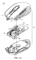
- FIG. lA is an exploded view of the computer input device according to a first embodiment;
-
FIG. 1B is an exploded view of the computer input device according to the first embodiment; -
FIG. 1C is an exploded view of the computer input device according to the first embodiment; -
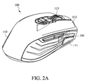
FIG. 2A is an perspective view of the computer input device according to the first embodiment; -
FIG. 2B is an perspective view of the computer input device according to the first embodiment; -
FIG. 3 is a connection diagram of the computer input device according to the first embodiment; -
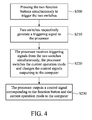
FIG. 4 is a flowchart of the mode switching method for operation modes according to the first embodiment; -
FIG. 5 is an exploded view of the computer input device according to a second embodiment; -
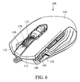
FIG. 6 is a perspective view of the computer input device according to the second embodiment; -
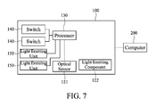
FIG. 7 is a connection diagram of the computer input device according to the second embodiment; and -
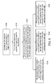
FIG. 8 is a flowchart of the mode switching method for operation modes according to the second embodiment. - Refer to FIG. lA to
FIG. 4 , acomputer input device 100 withswitchable operation modes 100 is able to electronically connected to acomputer 200, so as to execute the default function of thecomputer input device 100 in a operating system of thecomputer 200. - The
computer 200 could be a desktop computer, a notebook computer, or any electronics that are able to be connected to peripheral devices, not limited as described herein. Thecomputer input device 100 of this disclosure includes but not limits to a mouse, a trackball, a joysticks, etc. In the following description, a mouse will be the preferred embodiment. A person skilled in the art can make proper modification to thecomputer input device 100 according to the actual needs or design requirements, not limited as described herein. - Refer to FIG. lA to
FIG. 3 , thecomputer input device 100 includes abody 110, aPCB 120, aprocessor 130, and twoswitches 140. Thebody 110 has an upper and a lower casting and forms an accommodation room inside. Twofunction buttons 111 are disposed on the upper casting of thebody 110 and able to be pressed back and forth with respect to thebody 110. Twobuttons 112 and ascroll wheel 113 are also disposed on the upper casting of thebody 110, so as to execute the default functions of the mouse. The twofunction buttons 111 according to the first embodiment are disposed to the opposite sides of the upper casting. The positions of the twofunction buttons 111 correspond to those of the thumb and the ring finger of a user when the user uses thecomputer input device 100, whether a left-handed user or a right-handed user can use intuitively. Thebutton 112 and thescroll wheel 113 are common components of mice in the prior art and have the same functions as mice in the prior art, so the inventor will not repeat here. - The
PCB 120 of thecomputer input device 100 is disposed inside thebody 110, and anoptical sensor 121 and alight emitting component 122 are electronically disposed on the side facing thePCB 120 of the lower casting. The combination of theoptical sensor 121 and light emittingcomponent 122 is to optically detect the displacement distance of thecomputer input device 100, so as to control a cursor in the operating system by transmitting a displacement signal to thecomputer 200. The technology of optical displacement distance detection is a common detection technology, so the inventor will not repeat here. A person skilled in the art can also choose to mechanically detect the displacement distance according to the actual needs or design requirements, not limited as described herein, and thelight emitting component 122 includes but not limits to a light emitting diode or a bulb. - The
processor 130 is electronically disposed on thePCB 120, and theprocessor 130 according to the first embodiment is a microcontroller unit, for integrating and coordinating the electrical control and actuation of the computer input device. Theprocessor 130 outputs a first control signal corresponding to the first operation mode to thecomputer 200; or theprocessor 130 outputs a second control signal corresponding to the second operation mode to thecomputer 200. At the same time, the operating system in thecomputer 200 executes the corresponding actuations in the first operation mode or the second operation mode. - The first operation mode is suitable for right-handed users, and the second operation mode is suitable for left-handed users. When the
processor 130 transmits control signals corresponding to the first operation mode to thecomputer 200, the operating system directly adopts the right-handed operation mode to control the cursor; when theprocessor 130 transmits control signals corresponding to the second operation mode to thecomputer 200, the operating system directly adopts the left-handed operation mode to control the cursor. That is to say, thecomputer 200 only needs to receive the control signals transmitted from thecomputer input device 100, and the operating system directly adopt the corresponding operation mode, without adjusting the setting of the mouse in the operating system. A person skilled in the art can set the first operation mode as the left-handed operation mode and the second operation mode as the right-handed operation mode according to the actual needs or design requirements, not limited as described herein. - Refer to
FIG. 1A to FIG. 4 , the twoswitches 140 are disposed on thePCB 120 and are electronically connected to theprocessor 130. The positions of the twoswitches 140 respectively correspond to the positions of the twofunction buttons 111 on thebody 110. The mode switching method for operation modes is described in the following: when users press the twofunction buttons 111 simultaneously, the twofunction buttons 111 move toward inside due to the pressings and trigger the two switches 140 (S200); meanwhile, the twoswitches 140 respectively generate a triggering signal to the processor 130 (S210); when theprocessor 130 receives triggering signals from the twoswitches 140 simultaneously, theprocessor 130 switches the current operation mode and changes the control signals outputting to the computer 200 (5220). - Specifically, when the
processor 130 outputs control signals corresponding to the first operation mode, right-handed users can directly use thecomputer input device 100 in the right-handed operation mode of the operating system. If now a left-handed user wants to use thecomputer input device 100, the user can first press twofunction buttons 111, so as to trigger the twoswitches 140 to simultaneously generate and transmit the triggering signals to the processor (S200 and S210). At the same time, theprocessor 130 switches the first operation mode to the second operation mode and outputs control signals corresponding to the second operation mode to the computer 200 (S220). Then the operating system controls the cursor in the left-handed operation mode, such that the left-handed user can conveniently operate thecomputer device 200. If now the user becomes a right-handed one, the user only needs to repeats the above steps, and thecomputer input device 100 switches the second operation mode to the first operation mode and outputs the corresponding control signals to thecomputer 200. - Therefore, users only need to switch the operation modes via the
computer input device 100, without adjusting the setting of the mouse in the operating system of thecomputer device 200. Besides, thecomputer input device 100 does not switch the current operation mode in the operating system, and the control signals generated by thecomputer input device 100 deals with the associated determination. - For avoiding accidentally pressing the
function buttons 111 leading to incorrect setting, theprocessor 130 is set that only when theprocessor 130 continuously receives the triggering signals transmitted by theswitches 140 over a certain time, say, at least 3 seconds, theprocessor 130 switches to the other operation mode. In other words, if a user presses only onefunction button 111, or the time thatprocessor 130 simultaneously receives the triggering signals from the twofunction buttons 111 does not reach the default time, theprocessor 130 will not switch the current operation mode, so as to avoid accidentally pressing. A person skilled in the art can extend or shorten the time thatprocessor 130 simultaneously receives the triggering signals from the two function buttons 111 I according to the actual needs or design requirements, not limited as described herein. - For better performance of the
computer input device 100, the twofunction buttons 111 are respectively further able to execute a default function, such as the hotkey function, the macro function, or the resolution adjusting function. Specifically, when a user presses onefunction button 111 and triggers thecorresponding switch 140, theswitch 140 generates and transmits a triggering signal to theprocessor 130. Then theprocessor 130 does not switch the current operation mode, but outputs a control signal corresponding to the function button and the current operation mode to the computer 200 (S230), so as to execute the default function in the operating system. Therefore, thecomputer input device 100 integrates different operating functions. Except for thefunction button 111, the electronic signals generated by thebutton 112 and thescroll wheel 113 are also able to be transmitted to thecomputer 200 corresponding to the current operation mode by theprocessor 130, so as to execute the default functions. - Besides, only when the two
switches 140 are continuously triggered, theprocessor 130 switches to the other operation mode. Therefore, theprocessor 130 will not accidentally switch to the other operation mode if a user presses only onefunction button 111. - Refer to
FIG. 5 to FIG. 8 , the components and the mode switching method of thecomputer input method 100 according to the second embodiment are similar to those according to the first embodiment, the inventor will describe in detail only the difference of the two embodiments. - The
computer input device 100 according to the second embodiment includes abody 110, aPCB 120, a processor 13, twoswitches 140 and two light emittingunits 150. Twofunction buttons 111 are disposed on the upper casting of thebody 110 and able to be pressed with respect to thebody 110. ThePCB 120 is disposed inside thebody 110, and theprocessor 130 and twoswitches 140 are disposed on and electronically connected to thePCB 120. - The two light emitting
units 150 are disposed on thePCB 120 and electronically connected to theprocessor 130. The positions of the two light emittingunits 150 respectively correspond to the twofunction buttons 111 on thebody 110. Thelight emitting units 150 includes but not limits to light emitting diodes or bulbs. - The
light emitting units 150 generates optical signals for representing the operation mode in which thecomputer input device 100 is. Specifically, the mode switching method for operation modes is described in the followings: when theprocessor 130 outputs control signals corresponding to the first operation mode, theprocessor 130 drives thelight emitting unit 150 on the left side of thePCB 120 to emit light on thefunction button 111 on the left side of the body 110 (S240), such that the right-handed user can visually observe an optical signal on the left side of thebody 110, which represents thecomputer input device 100 is in the right-handed operation mode; if theprocessor 130 outputs control signals corresponding to the second operation mode, theprocessor 130 drives thelight emitting unit 150 on the right side of thePCB 120 to emit light on thefunction button 111 on the right side of the body 110 (S250), such that the left-handed user can visually observe an optical signal on the right side of thebody 110, which represents thecomputer input device 100 is in the left-handed operation mode. - When a right-handed user uses the
computer input device 100 by his right hand, most fingers of the user are on the right side of thebody 110, and the user can directly observe whether the optical signal exists on the lift side of thebody 110, such that the user can understand the current operation mode instantly and intuitively. If the user does not observe the light signal on the left side, the user can determine that thecomputer input device 100 is not in the right-handed operation mode. Then the user can press the twofunction buttons 111 to switch the operation mode, and the user does not need to adjust the setting of the mouse in the operating system, hence saving a lot of setting time; a left-handed user can determine the current operation mode in a similar way. - Overall, the computer input device directly control the processor to switch the operation mode, so that after receiving the triggering signal from the buttons or the function button, the processor outputs the control signal corresponding to the current operation mode, and the operating system directly executes the default functions in the operating system. Users need not to determine the current operation mode and adjust or readjust the setting of the mouse in the operating system, and the control signals transmitted by the computer input device will deal with the associated issues, increasing the convenience a lot.
Claims (10)
- A computer input device (100) with switchable operation modes, electronically connected to a computer (200), comprising:a body (110), including two function buttons (111) being pressed to move back and forth with respect to the body (110);a printed-circuit-board (120), disposed in the body (110);a processor (130), electronically connected to the printed-circuit-board (120), wherein the processor (130) outputs a first control signal corresponding to a first operation mode or a second control signal corresponding to a second operation mode to the computer (200); andtwo switches (140), disposed on the printed-circuit-board (120), respectively corresponding to the positions of the two function buttons (111), electrically connected to the processor (130), wherein while the two switches (140) are respectively triggered by the pressing of the two function buttons (111), the two switches (140) respectively generate and transmit a triggering signal to the processor (130);wherein when the processor (130) receives the two triggering signals from the two switches (140) simultaneously, the processor (130) switches the first operation mode to the second operation mode and outputs control signals corresponding to the second operation mode to the computer (200); or the processor (130) switches the second operation mode to the first operation mode and outputs control signals corresponding to the first operation mode to the computer (200).
- The computer input device (100) of claim 1, wherein the processor (130) switches the computer input device (100) to the first operation mode or the second operation mode after the processor (130) continuously and simultaneously receives triggering signals from the two switches (140) over a default time.
- The computer input device (100) of claim 1, wherein when the processor (130) receives a triggering signal from one of the switches (140), the processor (130) outputs a control signal corresponding to the current operation mode to the computer (200).
- The computer input device (100) of claim 1, further including two light emitting units (150), wherein the two light emitting units (150) are disposed on the printed-circuit-board (120), corresponding to the positions of the two function buttons (111), electronically connected to the processor (130); when the computer input device (100) switches computer input device (100) to the first operation mode, the processor (130) drives one of the light emitting units (150) to emit light, and when the computer input device (100) switches computer input device (100) to the second operation mode, the processor (130) drives the other light emitting unit (150) to emit light.
- The computer input device (100) of claim 1, wherein the two function buttons (111) are respectively disposed to the two opposite side surfaces of the body (110).
- The computer input device (100) of claim 1, wherein the first operation mode is for left-handed users, and the second operation mode is for the right-handed users.
- A mode switching method, applying to a computer input device (100) for switching operation modes, comprising the steps of:pressing two function buttons (111) simultaneously, so as to trigger two switches (140);generating and transmitting a triggering signal to a processor (130) via the two switches (140) respectively; andreceiving the two triggering signals via the processor (130) simultaneously, and then switching the computer input device (100) to a first operation mode and outputting a control signal corresponding to the first operation mode to a computer (200) via the processor (130); or switching the computer (200) to a second operation mode and outputting a control signal corresponding to the second operation mode to the computer (200) via the processor (130).
- The mode switching method of claim 7, wherein in the step of receiving the two triggering signals via the processor (130) simultaneously, switching the computer input device (100) to the first operation mode or the second operation mode is only executed after the processor (130) continuously receives the two triggering signals over a default time.
- The mode switching method of claim 7, further including the step of:receiving one of the triggering signal via the processor (130), so as to output a control signal corresponding to the current operation mode to the computer (200).
- The switching method for operation modes of claim 7, further includes the steps of:driving one light emitting unit (150) to emit light via the processor (130) when the computer input device (100) is switched to the first operation mode; anddriving the other light emitting unit (150) to emit light via the processor (130) when the computer input device (100) is switched to the second operation mode.
Applications Claiming Priority (1)
| Application Number | Priority Date | Filing Date | Title |
|---|---|---|---|
| TW101125671A TWI544370B (en) | 2012-07-17 | 2012-07-17 | Computer input device with operation modes and method thereof |
Publications (2)
| Publication Number | Publication Date |
|---|---|
| EP2687952A2 true EP2687952A2 (en) | 2014-01-22 |
| EP2687952A3 EP2687952A3 (en) | 2016-06-29 |
Family
ID=48044602
Family Applications (1)
| Application Number | Title | Priority Date | Filing Date |
|---|---|---|---|
| EP13161055.2A Ceased EP2687952A3 (en) | 2012-07-17 | 2013-03-26 | Computer input device with switchable operation modes and mode switching method thereof |
Country Status (4)
| Country | Link |
|---|---|
| US (1) | US9024879B2 (en) |
| EP (1) | EP2687952A3 (en) |
| CN (1) | CN103543850B (en) |
| TW (1) | TWI544370B (en) |
Cited By (1)
| Publication number | Priority date | Publication date | Assignee | Title |
|---|---|---|---|---|
| USD1006018S1 (en) * | 2021-04-30 | 2023-11-28 | Logitech Europe S.A. | Mouse |
Families Citing this family (6)
| Publication number | Priority date | Publication date | Assignee | Title |
|---|---|---|---|---|
| CN105446498A (en) * | 2014-06-30 | 2016-03-30 | 致伸科技股份有限公司 | Mouse device with prompting function |
| TWI748414B (en) * | 2020-04-17 | 2021-12-01 | 威剛科技股份有限公司 | Computer peripherals |
| WO2021208054A1 (en) * | 2020-04-17 | 2021-10-21 | 威刚科技股份有限公司 | Computer peripheral set |
| USD1014504S1 (en) * | 2021-05-27 | 2024-02-13 | Hewlett-Packard Development Company, L.P. | Computer mouse |
| CA3242719A1 (en) * | 2021-12-29 | 2023-07-06 | Voyetra Turtle Beach, Inc. | MOUSE DEVICE WITH A BUTTON FEATURING MULTIPLE TOUCH ZONES |
| CA3242742A1 (en) | 2021-12-29 | 2023-07-06 | Voyetra Turtle Beach, Inc. | MOUSE DEVICE FEATURING A MULTI-TOUCH REGION ON A BUTTON |
Citations (1)
| Publication number | Priority date | Publication date | Assignee | Title |
|---|---|---|---|---|
| US20050275621A1 (en) * | 2003-06-16 | 2005-12-15 | Humanscale Corporation | Ergonomic pointing device |
Family Cites Families (12)
| Publication number | Priority date | Publication date | Assignee | Title |
|---|---|---|---|---|
| JPH11327762A (en) | 1998-05-11 | 1999-11-30 | Misawa Homes Co Ltd | Input device provided with mouse function |
| US6336052B1 (en) * | 1998-07-08 | 2002-01-01 | Forensic Technology Wai Inc. | Data acquistion image analysis image manipulation interface |
| US8199107B2 (en) * | 2004-12-22 | 2012-06-12 | University Of Waterloo | Input interface device with transformable form factor |
| US7710397B2 (en) * | 2005-06-03 | 2010-05-04 | Apple Inc. | Mouse with improved input mechanisms using touch sensors |
| US8917235B2 (en) * | 2005-11-14 | 2014-12-23 | Avago Technologies General Ip (Singapore) Pte. Ltd. | User control input device |
| US20070146326A1 (en) * | 2005-12-23 | 2007-06-28 | Tomaini John C | Silent computer mouse |
| CN101216743A (en) * | 2007-01-04 | 2008-07-09 | 鸿富锦精密工业(深圳)有限公司 | A mouse that can freely switch the left and right buttons |
| US20100127983A1 (en) * | 2007-04-26 | 2010-05-27 | Pourang Irani | Pressure Augmented Mouse |
| CN101477417A (en) * | 2008-01-03 | 2009-07-08 | 鸿富锦精密工业(深圳)有限公司 | Mouse system and method with free left/right hands operation mode switching function |
| JP4291405B1 (en) * | 2008-11-14 | 2009-07-08 | 健治 吉田 | Mouse with dot pattern reading function |
| CN102243539A (en) * | 2010-05-10 | 2011-11-16 | 中强光电股份有限公司 | Optical device and projection system |
| TWI493387B (en) * | 2011-11-18 | 2015-07-21 | Primax Electronics Ltd | Multi-touch mouse |
-
2012
- 2012-07-17 TW TW101125671A patent/TWI544370B/en not_active IP Right Cessation
- 2012-09-21 CN CN201210353472.6A patent/CN103543850B/en not_active Expired - Fee Related
-
2013
- 2013-03-16 US US13/844,908 patent/US9024879B2/en not_active Expired - Fee Related
- 2013-03-26 EP EP13161055.2A patent/EP2687952A3/en not_active Ceased
Patent Citations (1)
| Publication number | Priority date | Publication date | Assignee | Title |
|---|---|---|---|---|
| US20050275621A1 (en) * | 2003-06-16 | 2005-12-15 | Humanscale Corporation | Ergonomic pointing device |
Cited By (1)
| Publication number | Priority date | Publication date | Assignee | Title |
|---|---|---|---|---|
| USD1006018S1 (en) * | 2021-04-30 | 2023-11-28 | Logitech Europe S.A. | Mouse |
Also Published As
| Publication number | Publication date |
|---|---|
| EP2687952A3 (en) | 2016-06-29 |
| TWI544370B (en) | 2016-08-01 |
| US20140022173A1 (en) | 2014-01-23 |
| TW201405372A (en) | 2014-02-01 |
| US9024879B2 (en) | 2015-05-05 |
| CN103543850B (en) | 2017-03-01 |
| CN103543850A (en) | 2014-01-29 |
Similar Documents
| Publication | Publication Date | Title |
|---|---|---|
| US9024879B2 (en) | Computer input device with switchable operation modes and mode switching method thereof | |
| CN101228499B (en) | Mouse and its operation method | |
| US7916120B2 (en) | Hybrid presentation controller and computer input device | |
| TWI803704B (en) | Analog input device, computing system and method for receiving and processing analog input | |
| US20110221676A1 (en) | Optical mouse with touch sensitive top | |
| US20110090148A1 (en) | Wearable input device | |
| US20110109553A1 (en) | Wireless touchpad mouse | |
| US12124643B2 (en) | Mouse input function for pen-shaped writing, reading or pointing devices | |
| JP2015532736A (en) | Improved devices for use with computers | |
| US9329707B2 (en) | Input device | |
| US20140253453A1 (en) | Computer Display Object Controller | |
| US9836138B2 (en) | Touch pen | |
| EP2141581A1 (en) | Cursor control device | |
| KR200401975Y1 (en) | A controlling device for computer | |
| CN202049448U (en) | Mouse with touch panel | |
| JP5433063B1 (en) | PC input device | |
| TWI773353B (en) | Electronic device | |
| CN107092368B (en) | Touch control pen | |
| US20140320419A1 (en) | Touch input device | |
| US20190025938A1 (en) | Silent input module and silent feedback unit | |
| TWI910302B (en) | Analog input device, and method of controlling a lighting arrangement of the analog input device | |
| US8581846B2 (en) | Sensing computer mouse having touch-sensitive members disposed on curved bottom surface | |
| US20210373759A1 (en) | Touch operation method and touch device using the same | |
| CN117093079A (en) | Portable touch interactive keyboard | |
| TW201901369A (en) | Electronic system and method of operation |
Legal Events
| Date | Code | Title | Description |
|---|---|---|---|
| PUAI | Public reference made under article 153(3) epc to a published international application that has entered the european phase |
Free format text: ORIGINAL CODE: 0009012 |
|
| AK | Designated contracting states |
Kind code of ref document: A2 Designated state(s): AL AT BE BG CH CY CZ DE DK EE ES FI FR GB GR HR HU IE IS IT LI LT LU LV MC MK MT NL NO PL PT RO RS SE SI SK SM TR |
|
| AX | Request for extension of the european patent |
Extension state: BA ME |
|
| PUAL | Search report despatched |
Free format text: ORIGINAL CODE: 0009013 |
|
| AK | Designated contracting states |
Kind code of ref document: A3 Designated state(s): AL AT BE BG CH CY CZ DE DK EE ES FI FR GB GR HR HU IE IS IT LI LT LU LV MC MK MT NL NO PL PT RO RS SE SI SK SM TR |
|
| AX | Request for extension of the european patent |
Extension state: BA ME |
|
| RIC1 | Information provided on ipc code assigned before grant |
Ipc: G06F 3/023 20060101ALI20160524BHEP Ipc: G06F 3/0354 20130101AFI20160524BHEP |
|
| 17P | Request for examination filed |
Effective date: 20161018 |
|
| RBV | Designated contracting states (corrected) |
Designated state(s): AL AT BE BG CH CY CZ DE DK EE ES FI FR GB GR HR HU IE IS IT LI LT LU LV MC MK MT NL NO PL PT RO RS SE SI SK SM TR |
|
| STAA | Information on the status of an ep patent application or granted ep patent |
Free format text: STATUS: EXAMINATION IS IN PROGRESS |
|
| 17Q | First examination report despatched |
Effective date: 20170706 |
|
| STAA | Information on the status of an ep patent application or granted ep patent |
Free format text: STATUS: THE APPLICATION HAS BEEN REFUSED |
|
| 18R | Application refused |
Effective date: 20181130 |