EP2687882A1 - Optical fiber and manufacturing method thereof - Google Patents
Optical fiber and manufacturing method thereof Download PDFInfo
- Publication number
- EP2687882A1 EP2687882A1 EP11860920.5A EP11860920A EP2687882A1 EP 2687882 A1 EP2687882 A1 EP 2687882A1 EP 11860920 A EP11860920 A EP 11860920A EP 2687882 A1 EP2687882 A1 EP 2687882A1
- Authority
- EP
- European Patent Office
- Prior art keywords
- optical fiber
- light
- emitting end
- aperture
- core
- Prior art date
- Legal status (The legal status is an assumption and is not a legal conclusion. Google has not performed a legal analysis and makes no representation as to the accuracy of the status listed.)
- Granted
Links
Images








Classifications
-
- G—PHYSICS
- G02—OPTICS
- G02B—OPTICAL ELEMENTS, SYSTEMS OR APPARATUS
- G02B6/00—Light guides; Structural details of arrangements comprising light guides and other optical elements, e.g. couplings
- G02B6/24—Coupling light guides
- G02B6/26—Optical coupling means
- G02B6/262—Optical details of coupling light into, or out of, or between fibre ends, e.g. special fibre end shapes or associated optical elements
-
- B—PERFORMING OPERATIONS; TRANSPORTING
- B23—MACHINE TOOLS; METAL-WORKING NOT OTHERWISE PROVIDED FOR
- B23K—SOLDERING OR UNSOLDERING; WELDING; CLADDING OR PLATING BY SOLDERING OR WELDING; CUTTING BY APPLYING HEAT LOCALLY, e.g. FLAME CUTTING; WORKING BY LASER BEAM
- B23K26/00—Working by laser beam, e.g. welding, cutting or boring
- B23K26/36—Removing material
- B23K26/38—Removing material by boring or cutting
- B23K26/382—Removing material by boring or cutting by boring
- B23K26/386—Removing material by boring or cutting by boring of blind holes
-
- B—PERFORMING OPERATIONS; TRANSPORTING
- B23—MACHINE TOOLS; METAL-WORKING NOT OTHERWISE PROVIDED FOR
- B23K—SOLDERING OR UNSOLDERING; WELDING; CLADDING OR PLATING BY SOLDERING OR WELDING; CUTTING BY APPLYING HEAT LOCALLY, e.g. FLAME CUTTING; WORKING BY LASER BEAM
- B23K26/00—Working by laser beam, e.g. welding, cutting or boring
- B23K26/36—Removing material
- B23K26/38—Removing material by boring or cutting
- B23K26/382—Removing material by boring or cutting by boring
- B23K26/389—Removing material by boring or cutting by boring of fluid openings, e.g. nozzles, jets
-
- G—PHYSICS
- G02—OPTICS
- G02B—OPTICAL ELEMENTS, SYSTEMS OR APPARATUS
- G02B6/00—Light guides; Structural details of arrangements comprising light guides and other optical elements, e.g. couplings
- G02B6/02—Optical fibres with cladding with or without a coating
- G02B6/02052—Optical fibres with cladding with or without a coating comprising optical elements other than gratings, e.g. filters
-
- G—PHYSICS
- G02—OPTICS
- G02B—OPTICAL ELEMENTS, SYSTEMS OR APPARATUS
- G02B6/00—Light guides; Structural details of arrangements comprising light guides and other optical elements, e.g. couplings
- G02B6/02—Optical fibres with cladding with or without a coating
- G02B6/02057—Optical fibres with cladding with or without a coating comprising gratings
- G02B6/02076—Refractive index modulation gratings, e.g. Bragg gratings
- G02B6/02123—Refractive index modulation gratings, e.g. Bragg gratings characterised by the method of manufacture of the grating
-
- G—PHYSICS
- G02—OPTICS
- G02B—OPTICAL ELEMENTS, SYSTEMS OR APPARATUS
- G02B6/00—Light guides; Structural details of arrangements comprising light guides and other optical elements, e.g. couplings
- G02B6/02—Optical fibres with cladding with or without a coating
- G02B6/032—Optical fibres with cladding with or without a coating with non solid core or cladding
-
- G—PHYSICS
- G02—OPTICS
- G02B—OPTICAL ELEMENTS, SYSTEMS OR APPARATUS
- G02B6/00—Light guides; Structural details of arrangements comprising light guides and other optical elements, e.g. couplings
- G02B6/24—Coupling light guides
- G02B6/25—Preparing the ends of light guides for coupling, e.g. cutting
-
- G—PHYSICS
- G02—OPTICS
- G02B—OPTICAL ELEMENTS, SYSTEMS OR APPARATUS
- G02B6/00—Light guides; Structural details of arrangements comprising light guides and other optical elements, e.g. couplings
- G02B6/02—Optical fibres with cladding with or without a coating
- G02B6/02057—Optical fibres with cladding with or without a coating comprising gratings
- G02B6/02061—Grating external to the fibre and in contact with the fibre, e.g. evanescently coupled, gratings applied to the fibre end
Definitions
- the present invention relates to an optical fiber and a manufacturing method thereof, particularly to an optical fiber in which a beam control property of light emitting from an emitting end and a manufacturing method thereof.
- the optical fiber is a light guide member, in which the light incident at an incident end from a light source propagates and emits outward from the emitting end.
- the optical fiber includes a core that is of a core wire, a clad that covers an outside of the core, and a coating material that covers the outside of the clad.
- the optical fiber is configured such that the light propagates in the core by reflecting the light at an interface between the core and the clad using a difference in refractive index between the core and the clad.
- an additional external optical system typified by various lenses is frequently connected to the emitting end of the optical fiber. Therefore, the external optical system performs beam control of the light emitting from the emitting end of the optical fiber.
- Patent Document 1 surface removal processing is performed to form the lens by irradiating the emitting end with a laser beam, and the lens performs the beam control of the light emitting from the optical fiber.
- Patent Document 2 a refractive index change is induced to form the lens by irradiating the vicinity of the emitting end, and the lens performs the beam control of the light emitting from the optical fiber.
- the beam control of the light emitting from the optical fiber is performed using the external optical system
- the light emitting from the emitting end of the optical fiber includes light having a wide emitting angle corresponding to a numerical aperture of the optical fiber
- the external optical system having an effective diameter extremely larger than a core diameter of the optical fiber.
- the external optical system includes an aperture.
- the number of components of the external optical system increases, or it is necessary to accurately perform positioning between the external optical system including the aperture and the optical fiber.
- the beam control has low controllability, and the beam control can desirably be performed to only part of the light incident to the lens, which results in a problem in that a signal-to-noise ratio (an S/N ratio) of the light emitting from the optical fiber is significantly degraded.
- the present invention has been devised to solve the problems described above, and an object thereof is to provide an optical fiber, in which the beam control property of the light emitting from the emitting end is enhanced by adding the aperture function, and a manufacturing method thereof.
- an optical fiber includes: an incident end to which light is incident; and an emitting end from which the light emits.
- an aperture is provided in a core located at and/or near the emitting end, the aperture being formed by irradiating the core with an ultrashort pulsed laser beam having pulse widths of 10 -15 seconds to 10 -11 seconds.
- the aperture includes a light scattering region, the light scattering region being formed by inducing a damage change in part of the core through the irradiation of the ultrashort pulsed laser beam.
- the aperture includes a light absorption region, the light absorption region being formed by inducing blackening in part of the core through the irradiation of the ultrashort pulsed laser beam.
- the aperture has a disc shape, the aperture including an opening in a center thereof so as to surround an axis line of the core.
- the plural apertures are provided along the axis line of the core while separated from each other.
- the aperture has a cylindrical shape, the aperture including a hollow portion so as to surround the axis line of the core.
- the plural apertures are provided along a direction orthogonal to the axis line of the core while separated from each other.
- an optical element is provided on the emitting end side of a position where the aperture is formed.
- the optical element is formed by irradiating the core with the ultrashort pulsed laser beam having pulse widths of 10 -15 seconds to 10 -11 seconds.
- the optical element is a lens.
- the optical element is a volume diffractive optical element.
- the aperture includes a volume diffractive optical element, the volume diffractive optical element being formed by inducing a refractive index change in part of the core through the irradiation of the ultrashort pulsed laser beam.
- the aperture is formed in the core located at and/or near the emitting end by irradiating the core with the ultrashort pulsed laser beam from the emitting end side.
- the present invention can provide the optical fiber, in which the beam control property of the light emitting from the emitting end is enhanced by adding the aperture function, and the manufacturing method thereof.
- Fig. 1 is a view illustrating a configuration of a manufacturing apparatus that performs an optical fiber manufacturing method according to a first embodiment of the present invention.
- the optical fiber manufacturing method of the first embodiment will be described with reference to Fig. 1 .
- a manufacturing apparatus 100 that performs the optical fiber manufacturing method of the first embodiment is a laser machining apparatus that processes an aperture in an optical fiber 1 of a workpiece in which the aperture is not formed yet using an ultrashort pulsed laser beam (hereinafter also referred to as a femtosecond laser beam) having a pulse widths of 10 -15 seconds (1 femtosecond) to 10 -11 seconds (10 picoseconds).
- the manufacturing apparatus 100 mainly includes a laser source 101, optical systems 102 to 106 that are added to the laser source 101, and a holder 107 that holds the optical fiber 1.
- the laser source 101 is a part for irradiating the optical fiber 1 held by the holder 107 with a laser beam 200.
- the laser source 101 includes a titanium-sapphire crystal as a laser medium.
- the laser beam 200 emitted from the laser source 101 is the femtosecond laser beam.
- the optical systems added to the laser source 101 include an ND filter 102, an attenuator 103, an electromagnetic shutter 104, an aperture 105, and an objective lens 106.
- the ND filter 102, the attenuator 103, the electromagnetic shutter 104, the aperture 105, and the objective lens 106 are used to adjust energy (pulse energy), a processing pattern, a beam diameter, and a collective state of the laser beam 200.
- the holder 107 is a part for holding the optical fiber 1 that is of the workpiece.
- the holder 107 is driven in a translational three-axis direction including an X-axis direction, a Y-axis direction, and a Z-axis direction and a ⁇ -direction that is of a rotating direction about a Z-axis by a holder driving mechanism (not illustrated).
- the laser beam 200 emitted from the laser source 101 is controlled using the optical systems 102 to 106 while the holder 107 holding the optical fiber 1 that is of the workpiece in which the aperture is not formed yet is driven by the holder driving mechanism (not illustrated), thereby irradiating an emitting end of the optical fiber 1 with the laser beam 200 from the emitting end side.
- the laser processing (damage processing) is performed to a core 4 (see Figs. 2 and 3 ) located at the emitting end of the optical fiber 1 to form a light scattering region 5a (see Figs. 2 and 3 ) having a disc shape. Therefore, as described later, an optical fiber 1A of the first embodiment in which the aperture is provided is manufactured.
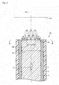
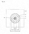
- Fig. 2 is a sectional view taken along a plane including the optical axis near the emitting end of the optical fiber according to the first embodiment of the present invention.
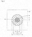
- Fig. 3 is a sectional view taken along a plane orthogonal to the optical axis near the emitting end of the optical fiber according to the first embodiment of the present invention, and is a view taken along a line III-III of Fig. 2 .
- Fig. 4 is a view illustrating a beam spot of light emitting from the emitting end of the optical fiber according to the first embodiment of the present invention, and is a view illustrating the beam spot in an observation plane OP orthogonal to an optical axis OA of the optical fiber 1A in Fig. 2 .
- the optical fiber 1A of the first embodiment will be described below with reference to Figs. 2 to 4 .
- the optical fiber 1A of the first embodiment includes the core 4 that is of a core wire, a clad 3 that covers an outside of the core 4, and a coating material 2 that covers the outside of the clad 3.
- the optical fiber 1A is constructed by one of a POF (Plastic Optical Fiber) and a GOF (Glass Optical Fiber), and the core 4 and the clad 3 are made of an optical transparency material.
- the material suitable for the damage processing is used as the specific material constituting the core 4 and the clad 3.
- a polymer material in which a molecular structure does not include a benzene ring can be cited.
- all glass materials can be cited.
- a polymethylmethacrylate (PMMA) resin and a cycloolefin polymer (COP) resin can be used as the polymer material in which the molecular structure does not include the benzene ring.
- the light scattering region 5a is provided in the core 4 located at the emitting end of the optical fiber 1A by performing the laser processing with the femtosecond laser beam.
- the light scattering region 5a is formed into the disc shape having an opening in a center, and provided so as to surround an axis line (that is, the optical axis OA of the optical fiber 1A) of the core 4.
- an axis line that is, the optical axis OA of the optical fiber 1A
- the light scattering region 5a having the disc shape is disposed in coaxial with the optical axis OA of the optical fiber 1A.
- the light scattering region 5a is a location that is formed by inducing the damage change through the laser processing with the femtosecond laser beam, and is a region where the light scattering region 5a includes micro irregularity from submicron orders to tens submicron orders, which is generated by resolidification or bubble formation. When the light scattering region 5a is irradiated with the light, the light scattering is generated by the micro irregularity.
- a radiation intensity of the light with which the light scattering region 5a is irradiated is weakened by the scattering in the light scattering region 5a compared with the light with which the light scattering region 5a is not irradiated (that is, the light with which the emitting end in the portion, in which the light scattering region 5a of the optical fiber 1A is not provided, is irradiated).
- the aperture is formed in the location where the light scattering region 5a is provided.
- the beam spot of the light emitting from the emitting end of the optical fiber 1A in the observation plane OP includes a small beam spot B (a diameter b) having the high radiation intensity and a large beam spot C (a diameter c) having the low radiation intensity.
- the beam spot B is the region irradiated with the light, which does not pass through the light scattering region 5a but emits from the emitting end of the optical fiber 1A
- the beam spot C is the region irradiated with the light, which emits from the emitting end of the optical fiber 1 A while passing through the light scattering region 5a to weaken the radiation intensity.
- the optical fiber including the core diameter of 0.5 mm at the emitting end and the numerical aperture of 0.5 (that is, the optical fiber that has the numerical aperture of 0.5 while an emitting diameter is restricted to 0.5 mm) can be formed.
- the aperture is constructed by forming the disc-shaped light scattering region 5a at the emitting end of the core 4, whereby the light emitting from the emitting end of the optical fiber 1A is properly narrowed down by the aperture. That is, a radiation intensity distribution in which the radiation intensity is enhanced near the optical axis OA can be provided to the light emitting from the emitting end of the optical fiber 1A, and the beam diameter can properly be narrowed down.
- the use of the configuration can enhance a beam control property of the light emitting from the emitting end of the optical fiber 1 A, and also enhance an S/N ratio.
- the optical fiber in which the beam control property of the light emitting from the emitting end is enhanced by adding the aperture function and the manufacturing method thereof can be implemented by adopting the optical fiber 1A of the first embodiment and the manufacturing method thereof.
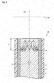
- Fig. 5 is a sectional view taken along the plane including the optical axis near the emitting end of an optical fiber according to a second embodiment of the present invention.
- Fig. 6 is a view illustrating the beam spot of the light emitting from the emitting end of the optical fiber according to the second embodiment of the present invention, and is a view illustrating the beam spot in the observation plane OP orthogonal to the optical axis OA of an optical fiber 1 B in Fig. 5 .
- the optical fiber 1 B of the second embodiment will be described below with reference to Figs. 5 and 6 .
- the light scattering region 5a is formed by performing the laser processing to the core 4 located near the emitting end of the optical fiber 1 B using the femtosecond laser beam, thereby providing the aperture. More particularly, the light scattering region 5a having the disc shape is formed in a position, which is retreated from the emitting end of the optical fiber 1 B along the optical axis OA of the optical fiber 1 B by a distance L1, so as to surround the optical axis OA, thereby forming the aperture:
- the distance L1 is a distance within a range, where the light with which the light scattering region 5a is not irradiated (that is, the light passing through the portion in which the light scattering region 5a of the optical fiber 1 B is not provided) reaches the emitting end without being reflected at the interface between the core 4 and clad 3 on the emitting end side of the light scattering region 5a.
- the configuration almost the light that scatters after the light scattering region 5a is irradiated therewith is incident to the clad 3 through the interface between the core 4 and the clad 3 on the emitting end side rather than in the light scattering region 5a.
- the optical fiber 1B of the second embodiment is manufactured using the manufacturing apparatus 100 of the first embodiment of the present invention.
- the laser beam 200 emitted from the laser source 101 is controlled using the optical systems 102 to 106 while the holder 107 holding the optical fiber 1 that is of the workpiece in which the aperture is not formed yet is driven by the holder driving mechanism (not illustrated), thereby irradiating the vicinity of the emitting end of the optical fiber 1 with the laser beam 200 from the emitting end side. Therefore, the laser processing (the damage processing) is performed to the core 4 (see Fig. 5 ) located in the vicinity of the emitting end of the optical fiber 1 to form the light scattering region 5a (see Fig. 5 ) having the disc shape. Accordingly, the optical fiber 1 B in which the aperture is provided is manufactured as described above.
- the beam spot of the light emitting from the emitting end of the optical fiber 1B in the observation plane OP includes the small beam spot B (the diameter b) having the high radiation intensity and the large beam spot C (the diameter c) having the low radiation intensity.
- the beam spot B is the region irradiated with the light, which does not pass through the light scattering region 5a but emits from the emitting end of the optical fiber 1 B
- the beam spot C is the region irradiated with the light, which is not incident to the clad 3 but emits from the emitting end of the optical fiber 1 B in the light passing through the light scattering region 5a to weaken the radiation intensity.
- the beam spot A (the diameter a) indicated by the broken line in Fig. 6 expresses the region where the observation plane OP is irradiated with the light unless the light scattering region 5a is provided in the optical fiber 1B. At this point, the relationship among the diameters of the beam spots satisfies a condition of b ⁇ a ⁇ c.
- the optical fiber in which the beam control property of the light emitting from the emitting end is further enhanced by adding the aperture function in addition to the effect of the first embodiment and the manufacturing method thereof can be implemented by adopting the optical fiber 1 B of the second embodiment and the manufacturing method thereof.
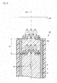
- Fig. 7 is a sectional view taken along the plane including the optical axis near the emitting end of an optical fiber according to a third embodiment of the present invention.
- Fig. 8 is a view illustrating the beam spot of light emitting from the emitting end of the optical fiber according to the third embodiment of the present invention, and is a view illustrating the beam spot in the observation plane OP orthogonal to the optical axis OA of an optical fiber 1C in Fig. 7 .
- the optical fiber 1C of the third embodiment will be described bellow with reference to Figs. 7 and 8 .
- the light scattering region 5a is formed by performing the laser processing to the core 4 located near the emitting end of the optical fiber 1C using the femtosecond laser beam, thereby providing the aperture. More particularly, the light scattering region 5a having the disc shape is formed in a position, which is retreated from the emitting end of the optical fiber 1C along the optical axis OA of the optical fiber 1C by a distance L2, so as to surround the optical axis OA, thereby forming the aperture.
- the distance L2 is a distance within a range, where at least part of the light with which the light scattering region 5a is not irradiated (that is, the light passing through the portion in which the light scattering region 5a of the optical fiber 1C is not provided) reaches the emitting end while being reflected at the interface between the core 4 and clad 3 on the emitting end side of the light scattering region 5a.
- the configuration almost the light that scatters after the light scattering region 5a is irradiated therewith is incident to the clad 3 through the interface between the core 4 and the clad 3 on the emitting end side rather than in the light scattering region 5a.
- the optical fiber 1C of the third embodiment is manufactured using the manufacturing apparatus 100 of the first embodiment of the present invention.
- the laser beam 200 emitted from the laser source 101 is controlled using the optical systems 102 to 106 while the holder 107 holding the optical fiber 1 that is of the workpiece in which the aperture is not formed yet is driven by the holder driving mechanism (not illustrated), thereby irradiating the vicinity of the emitting end of the optical fiber 1 with the laser beam 200 from the emitting end side. Therefore, the laser processing (the damage processing) is performed to the core 4 (see Fig. 7 ) located in the vicinity of the emitting end of the optical fiber 1 to form the light scattering region 5a (see Fig. 7 ) having the disc shape. Accordingly, the optical fiber 1C in which the aperture is provided is manufactured as described above.
- the beam spot of the light emitting from the emitting end of the optical fiber 1C in the observation plane OP includes the small beam spot B (the diameter b) having the high radiation intensity, the large beam spot C (the diameter c) having the low radiation intensity, and a beam spot D (a diameter d) having the diameter and radiation intensity intermediate between the beam spots B and C.
- the beam spot D is the region irradiated with the light, which emits from the emitting end of the optical fiber 1C while neither passing through the light scattering region 5a nor being reflected at the interface between the core 4 and the clad 3
- the beam spot C is the region irradiated with the light, which is not incident to the clad 3 but emits from the emitting end of the optical fiber 1C in the light passing through the light scattering region 5a to weaken the radiation intensity
- the beam spot B is the region irradiated with the light, which does not pass through the light scattering region 5a but is reflected at the interface between the core 4 and the clad 3 to emit from the emitting end of the optical fiber 1C.
- the beam spot A (the diameter a) indicated by the broken line in Fig. 8 expresses the region where the observation plane OP is irradiated with the light unless the light scattering region 5a is provided in the optical fiber 1C. At this point, the relationship among the diameters of the beam spots satisfies a condition of b ⁇ d ⁇ a ⁇ c.
- the optical fiber in which the beam control property of the light emitting from the emitting end is further enhanced by adding the aperture function in addition to the effect of the first embodiment and the manufacturing method thereof can be implemented by adopting the optical fiber 1C of the third embodiment and the manufacturing method thereof.
- Fig. 9 is a sectional view taken along the plane including the optical axis near the emitting end of an optical fiber according to a fourth embodiment of the present invention.
- Fig. 10 is a view illustrating a beam spot of light emitting from the emitting end of the optical fiber according to the fourth embodiment of the present invention, and is a view illustrating the beam spot in the observation plane OP orthogonal to the optical axis OA of an optical fiber 1D in Fig. 9 .
- the optical fiber 1 D of the fourth embodiment will be described below with reference to Figs. 9 and 10 .
- the light scattering regions 5a are formed into two layers by performing the laser processing to the core 4 located at and near the emitting end of the optical fiber 1 D, using the femtosecond laser beam, thereby providing the two apertures. More particularly, the disc-shape light scattering regions 5a are formed into the two layers at the emitting end of the optical fiber 1D and in the position, which is retreated from the emitting end of the optical fiber 1 D along the optical axis OA of the optical fiber 1 D by a distance L3, so as to surround the optical axis OA, thereby forming the two apertures along the optical axis OA while separated from each other.
- the distance L3 may be a distance within a range, where the light with which the light scattering region 5a is not irradiated (that is, the light passing through the portion in which the light scattering region 5a of the optical fiber 1 D is not provided) reaches the emitting end without being reflected at the interface between the core 4 and clad 3 on the emitting end side of the light scattering region 5a, or a distance within a range, where at least part of the light reaches the emitting end while being reflected at the interface between the core 4 and clad 3 on the emitting end side of the light scattering region 5a.
- the optical fiber 1 D of the fourth embodiment is manufactured using the manufacturing apparatus 100 of the first embodiment of the present invention.
- the laser beam 200 emitted from the laser source 101 is controlled using the optical systems 102 to 106 while the holder 107 holding the optical fiber 1 that is of the workpiece in which the aperture is not formed yet is driven by the holder driving mechanism (not illustrated), thereby irradiating the emitting end of the optical fiber 1 and the vicinity of the emitting end with the laser beam 200 from the emitting end side. Therefore, the laser processing (the damage processing) is performed to the core 4 (see Fig. 7 ) located at and near the emitting end of the optical fiber 1 to form the disc-shaped light scattering regions 5a (see Fig. 7 ) into two layers. Accordingly, the optical fiber 1 D in which the two apertures are provided is manufactured as described above.
- the beam spot of the light emitting from the emitting end of the optical fiber 1 D in the observation plane OP includes the small beam spot B (the diameter b) having the high radiation intensity and the large beam spot C (the diameter c) having the low radiation intensity.
- the beam spot B is the region irradiated with the light, which does not pass through the light scattering regions 5a of the two layers but emits from the emitting end of the optical fiber 1 D
- the beam spot C is the region irradiated with the light, which is not incident to the clad 3 but emits from the emitting end of the optical fiber 1 D in the light passing through one of the light scattering regions 5a of two layers to weaken the radiation intensity.
- the beam spot A (the diameter a) indicated by the broken line in Fig. 10 expresses the region where the observation plane OP is irradiated with the light unless the light scattering regions 5a of two layers are provided in the optical fiber 1 D. At this point, the relationship among the diameters of the beam spots satisfies a condition of b ⁇ a ⁇ c.
- the optical fiber in which the beam control property of the light emitting from the emitting end is further enhanced by adding the aperture function in addition to the effect of the first embodiment and the manufacturing method thereof can be implemented by adopting the optical fiber 1 D of the fourth embodiment and the manufacturing method thereof.
- Fig. 11 is a sectional view taken along the plane including the optical axis near the emitting end of an optical fiber according to a fifth embodiment of the present invention.
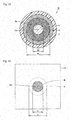
- Fig. 12 is a sectional view taken along the plane orthogonal to the optical axis near the emitting end of the optical fiber according to the fifth embodiment of the present invention, and is a view taken on a line XII-XII of Fig. 11 .
- Fig. 13 is a view illustrating the beam spot of the light emitting from the emitting end of the optical fiber according to the fifth embodiment of the present invention, and is a view illustrating the beam spot in the observation plane OP orthogonal to the optical axis OA of an optical fiber 1 E in Fig. 11 .
- the optical fiber 1 E of the fifth embodiment will be described bellow with reference to Figs. 11 to 13 .
- the optical fiber 1 E of the fifth embodiment includes the core 4 that is of the core wire, the clad 3 that covers the outside of the core 4, and the coating material 2 that covers the outside of the clad 3.
- the optical fiber 1 E is constructed by the POF, and the core 4 and the clad 3 are made of the optical transparency material.
- the material suitable for the blackening processing is used as the specific material constituting the core 4 and the clad 3, and the polymer material in which the molecular structure includes the benzene ring can be cited.
- the polycarbonate (PC) resin and the polyimide (PI) resin can be used as the polymer material in which the molecular structure includes the benzene ring.
- a light absorption region 5b is provided in the core 4 located at the emitting end of the optical fiber 1 E by performing the laser processing with the femtosecond laser beam.
- the light absorption region 5b is formed into the disc shape having the opening in the center, and provided so as to surround the axis line (that is, the optical axis OA of the optical fiber 1 E) of the core 4.
- the thickness of the light absorption region 5b along the direction of the optical axis OA but preferably the thickness ranges from about 0.005 mm to about 0.1 mm.
- the light absorption region 5b having the disc shape is disposed in coaxial with the optical axis OA of the optical fiber 1E.
- the optical fiber 1E of the fifth embodiment is manufactured using the manufacturing apparatus 100 of the first embodiment of the present invention.
- the laser beam 200 emitted from the laser source 101 is controlled using the optical systems 102 to 106 while the holder 107 holding the optical fiber 1 that is of the workpiece in which the aperture is not formed yet is driven by the holder driving mechanism (not illustrated), thereby irradiating the emitting end of the optical fiber 1 with the laser beam 200 from the emitting end side. Therefore, the laser processing (the blackening processing) is performed to the core 4 (see Figs. 11 and 12 ) located at the emitting end of the optical fiber 1 to form the light absorption region 5b (see Figs. 11 and 12 ) having the disc shape. Accordingly, the optical fiber 1 E in which the aperture is provided is manufactured as described above.
- the light absorption region 5b is the place formed by inducing the blackening through the laser processing with the femtosecond laser beam, and is the region generated by carbonization alteration.
- the light absorption region 5b is irradiated with the light, light absorption is mainly generated.
- part of the irradiation light is not absorbed by the light absorption region 5b but transmitted according to the generation of the carbonization alteration.
- the intensity of the transmitted light is extremely weakened, and the scattering is also generated. Therefore, the irradiation light has the radiation intensity to an extent to which the radiation intensity is substantially negligible.
- the light with which the light absorption region 5b is irradiated is absorbed by the light absorption region 5b to weaken the radiation intensity compared with the light with which the light absorption region 5b is not irradiated (that is, the light with which the emitting end at which the light absorption region 5b of the optical fiber 1 E is not provided).
- the aperture is formed in the place where the light absorption region 5b is provided.
- the beam spot of the light emitting from the emitting end of the optical fiber 1 E in the observation plane OP includes only the small beam spot B (the diameter b) having the high radiation intensity.
- the beam spot B is the region irradiated with the light, which does not pass through the light absorption region 5b but emits from the emitting end of the optical fiber 1 E.
- the beam spot A (the diameter a) indicated by the broken line in Fig. 13 expresses the region where the observation plane OP is irradiated with the light unless the light absorption region 5b is provided in the optical fiber 1 E.
- the relationship among the diameters of the beam spots satisfies a condition of b ⁇ a.
- the optical fiber including the core diameter of 0.5 mm at the emitting end and the numerical aperture of 0.5 (that is, the optical fiber that has the numerical aperture of 0.5 while the emitting diameter is restricted to 0.5 mm) can be formed.
- the aperture is constructed by forming the disc-shaped light absorption region 5b at the emitting end of the core 4, whereby the light emitting from the emitting end of the optical fiber 1 E is properly narrowed down by the aperture. That is, the radiation intensity distribution in which the radiation intensity is enhanced near the optical axis OA can be provided to the light emitting from the emitting end of the optical fiber 1 E, and the beam diameter can properly be narrowed down.
- the use of the configuration can enhance the beam control property of the light emitting from the emitting end of the optical fiber 1 E, and also enhance the S/N ratio.
- the beam control is further performed by the external optical system using the light emitting from the emitting end of the optical fiber 1 E, advantageously the lens having the small effective diameter can be used and it is not necessary to separately provide the aperture. Therefore, the downsizing of the external optical system, the decrease of the number of components, and the positioning simplification because of the decrease of the number of components can be implemented.
- the optical fiber in which the beam control property of the light emitting from the emitting end is enhanced by adding the aperture function and the manufacturing method thereof can be implemented by adopting the optical fiber 1 E of the fifth embodiment and the manufacturing method thereof.
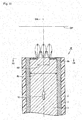
- Fig. 14 is a sectional view taken along the plane including the optical axis near the emitting end of an optical fiber according to a sixth embodiment of the present invention.
- Fig. 15 is a sectional view taken along the plane orthogonal to the optical axis near the emitting end of the optical fiber according to the sixth embodiment of the present invention, and is a view taken along a line XV-XV of Fig. 14 .
- An optical fiber 1 F of the first embodiment will be described bellow with reference to Figs. 14 and 15 .
- the light scattering region 5a is formed by performing the laser processing to the core 4 located at and near the emitting end of the optical fiber 1 F using the femtosecond laser beam.
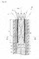
- the light scattering region 5a is continuously provided so as to reach a position, which is retreated from the emitting end of the optical fiber 1F along the optical axis OA of the optical fiber 1 F by a distance L4, thereby being formed into a cylindrical shape having a hollow portion, and the light scattering region 5a is provided so as to surround the axis line (that is, the optical axis OA of the optical fiber 1 F) of the core 4.
- the light scattering region 5a formed into the cylindrical shape has a sufficient length in the axial direction, and is discriminated from the disc-shaped light scattering region of the first embodiment from the viewpoint of an optical property.
- the light scattering region 5a having the cylindrical shape is disposed in coaxial with the optical axis OA of the optical fiber 1 F.
- the length (that is, the distance L4) in the axial direction of the cylindrical-shaped light scattering region 5a is set to a predetermined length, whereby an inner circumferential surface of the light scattering region 5a is irradiated with part of the light propagating in the core 4.
- the light with which the light scattering region 5a is irradiated is not totally reflected, but mainly scattered by light scattering region 5a. Therefore, as illustrated in Fig.
- the light scattering region 5a is irradiated with the light having an inclination larger than an inclination ⁇ with respect to the optical axis OA of the light, which propagates between the position of the incident end side of the inner circumferential surface of the light scattering region 5a and the position on the emitting end side of the inner circumferential surface of the light scattering region 5a so as to intersect the optical axis OA in a section including the optical axis OA, and the light having the inclination is scattered to weaken the radiation intensity.
- the aperture is formed in the place where the light scattering region 5a is provided.
- the optical fiber 1 F of the sixth embodiment is manufactured using the manufacturing apparatus 100 of the first embodiment of the present invention.
- the laser beam 200 emitted from the laser source 101 is controlled using the optical systems 102 to 106 while the holder 107 holding the optical fiber 1 that is of the workpiece in which the aperture is not formed yet is driven by the holder driving mechanism (not illustrated), thereby irradiating the emitting end of the optical fiber 1 and the vicinity of the emitting end with the laser beam 200 from the emitting end side. Therefore, the laser processing (the damage processing) is performed to the core 4 (see Figs. 14 and 15 ) located at and near the emitting end of the optical fiber 1 to form the cylindrical-shaped light scattering region 5a (see Figs. 14 and 15 ). Accordingly, the optical fiber 1F in which the aperture is provided is manufactured as described above.
- the light having the inclination larger than the inclination ⁇ with respect to the optical axis OA is scattered by the light scattering region 5a. Therefore, the light scattering region 5a is not irradiated with almost the light emitting from the emitting end of the optical fiber 1 F, but the light has the inclination smaller than the inclination ⁇ . Accordingly, as illustrated in Fig. 14 , the light emitting from the emitting end of the optical fiber 1 F becomes light 11 in which a maximum value of the emitting angle is restricted to a predetermined value, and the apparent numerical aperture of the optical fiber 1 F can be decreased on the emitting end side. In Fig. 14 , light 11' is the light emitting from the emitting end unless the light scattering region 5a is provided in the optical fiber 1 F.
- the cylindrical-shaped light scattering region including the hollow portion of a diameter R3 of 0.9 mm and the length or 5.0 mm and the radial thickness of 0.05 mm is provided in the optical fiber having the core of the diameter R1 of 1.0 mm and the numerical aperture of 0.5
- the property of the emitting light at the emitting end of the optical fiber can be equalized to the property of the emitting light at the emitting end side of the optical fiber having the numerical aperture of about a little less than 0.3.
- the aperture is constructed by forming the cylindrical-shaped light scattering region 5a at and near the emitting end of the core 4, whereby the light emitting from the emitting end of the optical fiber 1 F is properly narrowed down by the aperture.
- the light emitting from the emitting end of the optical fiber 1 F becomes the low-spread-angle light in which only the radiation intensity of the light is enhanced within the range of the desired emitting angle.
- only the light having the lower emitting angle can selectively emit from the emitting end of the optical fiber 1 F.
- the use of the configuration can enhance the beam control property of the light emitting from the emitting end of the optical fiber 1F, and also enhance the S/N ratio.
- the beam control is further performed by the external optical system using the light emitting from the emitting end of the optical fiber 1 F, advantageously the lens having the small effective diameter can be used and it is not necessary to separately provide the aperture. Therefore, the downsizing of the external optical system, the decrease of the number of components, and the positioning simplification because of the decrease of the number of components can be implemented.
- the optical fiber in which the beam control property of the light emitting from the emitting end is enhanced by adding the aperture function and the manufacturing method thereof can be implemented by adopting the optical fiber 1 F of the sixth embodiment and the manufacturing method thereof.
- Fig. 16 is a sectional view taken along the plane including the optical axis near the emitting end of an optical fiber according to a seventh embodiment of the present invention.
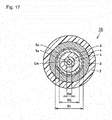
- Fig. 17 is a sectional view taken along the plane orthogonal to the optical axis near the emitting end of the optical fiber according to the seventh embodiment of the present invention, and is a view taken along a line XVII-XVII of Fig. 16 .
- An optical fiber 1G of the seventh embodiment will be described below with reference to Figs. 16 and 17 .
- the orbicular-zone light scattering regions 5a of two layers are formed by performing the laser processing to the core 4 located at and near the emitting end of the optical fiber 1 G using the femtosecond laser beam, thereby providing the one aperture that functions optically integrally.
- each of the orbicular-zone light scattering regions 5a of two layers is continuously provided so as to reach a position, which is retreated from the emitting end of the optical fiber 1 G along the optical axis OA of the optical fiber 1 G by a distance L5, thereby being formed into the cylindrical shape having the hollow portion, and the two light scattering regions 5a are provided while separated from each other in the direction orthogonal to the optical axis OA to form the one aperture that surrounds the optical axis OA.
- the optical fiber 1 G of the seventh embodiment is manufactured using the manufacturing apparatus 100 of the first embodiment of the present invention.
- the laser beam 200 emitted from the laser source 101 is controlled using the optical systems 102 to 106 while the holder 107 holding the optical fiber 1 that is of the workpiece in which the aperture is not formed yet is driven by the holder driving mechanism (not illustrated), thereby irradiating the emitting end of the optical fiber 1 and the vicinity of the emitting end with the laser beam 200 from the emitting end side. Therefore, the laser processing (the damage processing) is performed to the core 4 (see Figs.
- the optical fiber 1G is manufactured while the aperture that functions optically integrally is provided as described above.
- the aperture that exerts the optically-equal function can be constructed by the light scattering region 5a shortened along the axial direction.
- the cylindrical outside light scattering region including the hollow portion having the diameter R3 of 0.9 mm and the length of 1.7 mm and the radial thickness of 0.05 mm is provided in the optical fiber having the core diameter R1 of 1.0 mm and the numerical aperture of 0.5, and the cylindrical inside light scattering region including the hollow portion having the diameter R4 of 0.3 mm and the length of 1.7 mm and the radial thickness of 0.05 mm is further provided inside the outside light scattering region.
- the property of the emitting light on the emitting end side of the optical fiber can be equalized to the property of the emitting light on the emitting end side of the optical fiber having the numerical aperture of about a little less than 0.3.
- the optical fiber 1 G of the seventh embodiment and the manufacturing method thereof are adopted, in addition to the effect of the sixth embodiment, it is not necessary to irradiate the optical fiber to the deep position during the laser processing through which the light scattering region 5a is formed. Therefore, advantageously the aperture can easily be formed with no energy loss.
- Fig. 18 is a sectional view taken along the plane including the optical axis near the emitting end of an optical fiber according to an eighth embodiment of the present invention.
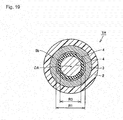
- Fig. 19 is a sectional view taken along the plane orthogonal to the optical axis near the emitting end of the optical fiber according to the eighth embodiment of the present invention, and is a view taken on a line XIX-XIX of Fig. 18 .
- An optical fiber 1H of the eighth embodiment will be described below with reference to Figs. 18 and 19 .
- the light absorption region 5b is formed by performing the laser processing to the core 4 located at the emitting end of the optical fiber 1 H and in the vicinity of the emitting end using the femtosecond laser beam.
- the light absorption region 5b is continuously provided so as to reach the position, which is retreated from the emitting end of the optical fiber 1 H along the optical axis OA of the optical fiber 1 H by the distance L4, thereby being formed into the cylindrical shape having the hollow portion, and the light absorption region 5b is provided so as to surround the axis line (that is, the optical axis OA of the optical fiber 1 H) of the core 4.
- the light absorption region 5b formed into the cylindrical shape has the sufficient length in the axial direction, and is discriminated from the disc-shaped light scattering region of the fifth embodiment from the viewpoint of the optical property.
- There is no particular limitation to the radial thickness of the light scattering region 5b but preferably the thickness ranges from about 0.005 mm to about 0.1 mm.
- the light absorption region 5b having the cylindrical shape is disposed in coaxial with the optical axis OA of the optical fiber 1 H.
- the length in the axial direction of the cylindrical-shaped light absorption region 5b is set to the predetermined length, whereby the inner circumferential surface of the light absorption region 5b is irradiated with part of the light propagating in the core 4.
- the light with which the light absorption region 5b is irradiated is not totally reflected, but mainly absorbed by light absorption region 5b. Therefore, as illustrated in Fig.
- the light absorption region 5b is irradiated with the light having the inclination larger than the inclination a with respect to the optical axis OA of the light, which propagates between the position on the incident end side of the inner circumferential surface of the light absorption region 5b and the position on the emitting end side of the inner circumferential surface of the light absorption region 5b so as to intersect the optical axis OA in the section including the optical axis OA, and the light having the inclination is absorbed to weaken the radiation intensity.
- the aperture is formed in the place where the light absorption region 5b is provided.
- the optical fiber 1 H of the eighth embodiment is manufactured using the manufacturing apparatus 100 of the first embodiment of the present invention.
- the laser beam 200 emitted from the laser source 101 is controlled using the optical systems 102 to 106 while the holder 107 holding the optical fiber 1 that is of the workpiece in which the aperture is not formed yet is driven by the holder driving mechanism (not illustrated), thereby irradiating the emitting end of the optical fiber 1 and the vicinity of the emitting end with the laser beam 200 from the emitting end side. Therefore, the laser processing (the blackening processing) is performed to the core 4 (see Figs. 18 and 19 ) located at or near the emitting end of the optical fiber 1 to form the cylindrical-shaped light absorption region 5b (see Figs. 18 and 19 ). Accordingly, the optical fiber 1H in which the aperture is provided is manufactured as described above.
- the light having the inclination larger than the inclination a with respect to the optical axis OA is absorbed by the light absorption region 5b. Therefore, the light absorption region 5b is not irradiated with almost the light emitting from the emitting end of the optical fiber 1H, but the light has the inclination larger than the inclination ⁇ . Accordingly, as illustrated in Fig. 18 , the light emitting from the emitting end of the optical fiber 1 H becomes light 11 in which the maximum value of the emitting angle is restricted to the predetermined value, and the apparent numerical aperture of the optical fiber 1 H can be decreased on the emitting end side. In Fig. 18 , light 11' is the light emitting from the emitting end unless the light scattering region 5a is provided in the optical fiber 1 H.
- the property of the emitting light at the emitting end side of the optical fiber can be equalized to the property of the emitting light at the emitting end side of the optical fiber having the numerical aperture of about a little less than 0.3.
- the aperture is constructed by forming the cylindrical-shaped light absorption region 5b at and near the emitting end of the core 4, whereby the light emitting from the emitting end of the optical fiber 1 H is properly narrowed down by the aperture.
- the light emitting from the emitting end of the optical fiber 1 H becomes the low-spread-angle light in which only the radiation intensity of the light is enhanced within the range of the desired emitting angle.
- only the light having the lower emitting angle can selectively emit from the emitting end of the optical fiber 1 H.
- the use of the configuration can enhance the beam control property of the light emitting from the emitting end of the optical fiber 1 H, and also enhance the S/N ratio.
- the beam control is further performed by the external optical system using the light emitting from the emitting end of the optical fiber 1 H, advantageously the lens having the small effective diameter can be used and it is not necessary to separately provide the aperture. Therefore, the downsizing of the external optical system, the decrease of the number of components, and the positioning simplification because of the decrease of the number of components can be implemented.
- the optical fiber in which the beam control property of the light emitting from the emitting end is enhanced by adding the aperture function and the manufacturing method thereof can be implemented by adopting the optical fiber 1 H of the eighth embodiment and the manufacturing method thereof.
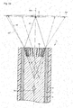
- Fig. 20 is a sectional view taken along the plane including the optical axis near the emitting end of an optical fiber according to a ninth embodiment of the present invention, and is a view schematically illustrating the beam spot of the light emitting from the emitting end of the optical fiber.
- An optical fiber 1I of the ninth embodiment will be described with reference to Fig. 20 .
- the optical fiber 1I of the ninth embodiment includes a lens 6 at the emitting end and in the vicinity of the emitting end in addition to the disc-shaped light scattering region 5a that acts as the aperture.
- Various lenses such as a Fresnel lens, a binary lens, and a refracting lens can be used as the lens 6.
- the Fresnel lens is used in the optical fiber 1I of the ninth embodiment.
- both the light scattering region 5a and the lens 6 can be formed by the laser processing using the manufacturing apparatus 100 of the first embodiment of the present invention.
- the light scattering region 5a is provided in a position retreated from the emitting end of the optical fiber 1I along the optical axis OA of the optical fiber 1I by a distance LF. At this point, it is assumed that the distance LF corresponds to a focal distance of the lens 6.
- the lens 6 is irradiated with the light. Therefore, the light emits from the emitting end of the optical fiber 1I while being converted into pseudo collimate light 12 traveling in substantially parallel with the optical axis OA of the optical fiber 1I.
- the beam spot in the observation plane OP orthogonal to the optical axis OA of the optical fiber 1I includes only a small beam spot E having the high radiation intensity as illustrated in Fig. 20 .
- Light 12' indicated by the broken line in Fig. 20 and the beam spot A express the light emitting from the emitting end and the region of the observation plane OP irradiated with the light unless the light scattering region 5a and the lens 6 are not provided in the optical fiber 1I.
- Light 12" indicated by an alternate long and two short dashes line in Fig. 20 and a beam spot E" express the light emitting from the emitting end and the region of the observation plane OP irradiated with the light when not the light scattering region 5a but only the lens 6 is provided in the optical fiber 1I.
- the lens having the numerical aperture of 0.5 is provided near the emitting end of the optical fiber having the core diameter R1 of 1.0 mm and the numerical aperture of 0.5, and the disc-shaped light scattering region including the opening having the diameter R2 of 0.1 mm and the thickness of 0.05 mm is provided in the position that is of the focal position of the lens and is 1.4 mm away from the emitting end of the optical fiber.
- the pseudo collimate light in which a half angle of the spread angle is restricted to about 3° emits from the emitting end.
- the lens 6 is formed at the emitting end of the core 4, and the disc-shape light scattering region 5a is formed in the focal position of the lens 6, which allows the beam control to be performed to the light emitting from the optical fiber 1I such that the desired light (in this case, the substantially parallel light in which the beam spot is properly narrowed down) is obtained.
- the use of the confguration can enhance the beam control property of the light emitting from the emitting end of the optical fiber 1I, and also enhance the S/N ratio.
- the beam control is further performed by the external optical system using the light emitting from the emitting end of the optical fiber 1I; advantageously the lens having the small effective diameter can be used and it is not necessary to separately provide the aperture. Therefore, the downsizing of the external optical system, the decrease of the number of components, and the positioning simplification because of the decrease of the number of components can be implemented.
- the optical fiber in which the beam control property of the light emitting from the emitting end is enhanced by adding the aperture function and the lens function and the manufacturing method thereof can be implemented by adopting the optical fiber 1I of the ninth embodiment and the manufacturing method thereof.
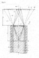
- Fig. 21 is a sectional view taken along the plane including the optical axis near the emitting end of an optical fiber according to a tenth embodiment of the present invention, and is a view schematically illustrating the beam spot of the light emitting from the emitting end of the optical fiber.
- An optical fiber 1 J of the tenth embodiment will be described with reference to Fig. 21 .
- the optical fiber 1J of the tenth embodiment differs from the optical fiber 1I of the ninth embodiment only in the position where the light scattering region 5a is formed. That is, in the optical fiber 1 J of the tenth embodiment, the light scattering region 5a is disposed in a finite position on the incident end side of the focal position of the lens 6. Specifically, the light scattering region 5a is provided in a position retreated from the emitting end of the optical fiber 1J along the optical axis OA of the optical fiber 1J by a distance s (at this point, the distance s is greater than the distance LF in Fig. 20 ).
- n is the refractive index of the core 4
- s' is the distance from the lens 6 to an image plane in a projection direction
- f is the focal distance of the lens 6.
- the beam spot in the observation plane OP (in this case, the observation plane OP is set to the image plane of the lens 6) orthogonal to the optical axis OA of the optical fiber 1 J includes only a small beam spot F having the high radiation intensity as illustrated in Fig. 21 .
- the light 12' indicated by the broken line in Fig. 21 and the beam spot A express the light emitting from the emitting end and the region of the observation plane OP irradiated with the light unless the light scattering region 5a and the lens 6 are not provided in the optical fiber 1J.
- the light 12" indicated by the alternate long and two short dashes line in Fig. 21 and the beam spot E" express the light emitting from the emitting end and the region of the observation plane OP irradiated with the light when not the light scattering region 5a but only the lens 6 is provided in the optical fiber 1J.
- the lens 6 is formed at the emitting end of the core 4, and the disc-shape light scattering region 5a is formed in the finite position of the lens 6, which allows the beam control to be performed to the light emitting from the optical fiber 1I such that the desired light (in this case, the light that is collected in the finite position by properly narrowing down the beam spot) is obtained.
- the use of the configuration can enhance the beam control property of the light emitting from the emitting end of the optical fiber 1J, and also enhance the S/N ratio.
- the beam control is further performed by the external optical system using the light emitting from the emitting end of the optical fiber 1J, advantageously the lens having the small effective diameter can be used and it is not necessary to separately provide the aperture. Therefore, the downsizing of the external optical system, the decrease of the number of components, and the positioning simplification because of the decrease of the number of components can be implemented.
- the optical fiber in which the beam control property of the light emitting from the emitting end is enhanced by adding the aperture function and the lens function and the manufacturing method thereof can be implemented by adopting the optical fiber 1J of the tenth embodiment and the manufacturing method thereof.
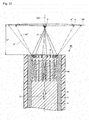
- Fig. 22 is a sectional view taken along the plane including the optical axis near the emitting end of an optical fiber according to an eleventh embodiment of the present invention, and is a view schematically illustrating the beam spot of the light emitting from the emitting end of the optical fiber of the eleventh embodiment.
- An optical fiber 1 K of the eleventh embodiment will be described with reference to Fig. 22 .
- the optical fiber 1 K of the eleventh embodiment differs from the optical fiber 1I of the ninth embodiment only in the shape of the light scattering region 5a. That is, in the optical fiber 1 K of the eleventh embodiment, the aperture includes the plural cylindrical-shaped light scattering regions 5a that surround the optical axis OA of the optical fiber 1 K, and the aperture is disposed close to the lens 6.
- the light propagating in the core 4 along the direction of the arrow 10 in Fig. 22 is narrowed down while the inclination of the light with respect to the optical axis of the optical fiber 1 K is restricted to the predetermined angle range by the aperture constructed by the formation of the light scattering regions 5a, and then the lens 6 is irradiated with the light. Therefore, the light with which the lens 6 is irradiated can substantially be parallelized, and a pseudo infinity projection state can be produced. Accordingly, light 14 emitting from the emitting end of the optical fiber 1K is collected to the substantially focal position (the vicinity of the position where the distance from the emitting end of the optical fiber 1 K is a focal distance Lf of the lens 6.
- the beam spot in the observation plane OP (in this case, the observation plane OP is set to the plane including the substantially focal position of the lens 6) orthogonal to the optical axis OA of the optical fiber 1 K includes only a small beam spot G having the high radiation intensity as illustrated in Fig. 22 .
- the light 12' indicated by the broken line in Fig. 22 and the beam spot A express the light emitting from the emitting end and the region of the observation plane OP irradiated with the light unless the light scattering region 5a and the lens 6 are not provided in the optical fiber 1 K.
- the light 12" indicated by the alternate long and two short dashes line in Fig. 22 and the beam spot E" express the light emitting from the emitting end and the region of the observation plane OP irradiated with the light when not the light scattering region 5a but only the lens 6 is provided in the optical fiber 1 K.
- the lens 6 is formed at the emitting end of the core 4, and the cylindrical-shaped light scattering region 5a is formed near the lens 6, which allows the beam control to be performed to the light emitting from the optical fiber 1 K such that the desired light (in this case, the light that is collected in the substantially focal position by properly narrowing down the beam spot) is obtained.
- the use of the configuration can enhance the beam control property of the light emitting from the emitting end of the optical fiber 1 K, and also enhance the S/N ratio.
- the beam control is further performed by the external optical system using the light emitting from the emitting end of the optical fiber 1 K, advantageously the lens having the small effective diameter can be used and it is not necessary to separately provide the aperture. Therefore, the downsizing of the external optical system, the decrease of the number of components, and the positioning simplification because of the decrease of the number of components can be implemented.
- the optical fiber in which the beam control property of the light emitting from the emitting end is enhanced by adding the aperture function and the lens function and the manufacturing method thereof can be implemented by adopting the optical fiber 1 K of the eleventh embodiment and the manufacturing method thereof.
- Fig. 23 is a sectional view taken along the plane including the optical axis near the emitting end of an optical fiber according to a twelfth embodiment of the present invention, and is a view schematically illustrating the beam spot of the light emitting from the emitting end of the optical fiber of the twelfth embodiment.
- An optical fiber 1L of the twelfth embodiment will be described with reference to Fig. 23 .
- the optical fiber 1L of the twelfth embodiment includes the core 4 that is of a core wire, the clad 3 that covers the outside of the core 4, and the coating material 2 that covers the outside of the clad 3.
- the optical fiber 1 L includes the POF, and the core 4 and the clad 3 are made of the optical transparency material.
- the material suitable for modification processing is used as the specific material constituting the core 4 and the clad 3.
- the polymer material in which the molecular structure does not includes the benzene ring can be cited.
- the polymer material in which the molecular structure does not includes the benzene ring can be cited.
- the polymer material in which the molecular structure does not include the benzene ring can be cited.
- the polymethylmethacrylate (PMMA) resin and the cycloolefin polymer (COP) resin can be used as the polymer material in which the molecular structure does not include the benzene ring.
- the polymer material such as the polycarbonate (PC) resin and the polyimide (PI) resin
- the modification processing can be performed by optimizing the pulse energy. Therefore, the polymer material in which the molecular structure includes the benzene ring can be used.
- a volume diffractive lens 5c that is of a volume diffractive optical element is provided in the core 4 located at the emitting end of the optical fiber 1L by performing the laser processing using the femtosecond laser beam described later.
- the emitting end of the optical fiber 1L and the vicinity of the emitting end are irradiated with the femtosecond laser beam to induce the refractive index change, thereby forming the volume diffractive lens 5c including aggregate of modification layers having a predetermined shape.
- the volume diffractive lens 5c has an angle dependence property with respect to the light incident to the lens, exerts the lens function only for the light incident at a predetermined principal ray angle or less, and directly transmits the light incident at an incident angle greater than the predetermined principal ray angle. Therefore, the volume diffractive lens 5c acts as a kind of aperture.
- ⁇ is a wavelength of the light incident to the volume diffractive lens 5c
- L is a modification thickness of the volume diffractive lens 5c
- n is the refractive index of the core 4
- ⁇ is a diffraction period of the volume diffractive lens 5c.
- the optical fiber 1L of the twelfth embodiment is manufactured using the manufacturing apparatus 100 of the first embodiment of the present invention.
- the laser beam 200 emitted from the laser source 101 is controlled using the optical systems 102 to 106 while the holder 107 holding the optical fiber 1 that is of the workpiece in which the aperture is not formed yet is driven by the holder driving mechanism (not illustrated), thereby irradiating the emitting end of the optical fiber 1 with the laser beam 200 from the emitting end side. Therefore, the laser processing (the modification processing) is performed to the core 4 (see Fig. 23 ) located at the emitting end of the optical fiber 1 to form the modification layer having the desired shape. Accordingly, the optical fiber 1 L in which the aperture including the volume diffractive lens 5c is provided is manufactured as described above.
- the radiation intensity distribution in which the radiation intensity is enhanced near the optical axis OA based on the angle dependence property of the volume diffractive lens 5c can be provided to light 15 emitting from the emitting end of the optical fiber 1L.
- light 15' incident to the volume diffractive lens 5c at the incident angle greater than a predetermined angle can directly be transmitted in the light propagating in the core 4 along the direction of the arrow 10 in Fig. 23 .
- the beam spot in the observation plane OP orthogonal to the optical axis OA of the optical fiber 1 L includes only a small beam spot H having the high radiation intensity and a large beam spot I having the low radiation intensity as illustrated in Fig. 23 .
- the beam spot H is the region irradiated with the light 15, which emits from the emitting end of the optical fiber 1 L after being refracted by the lens function of the volume diffractive lens 5c
- the beam spot I is the region irradiated with light 15", which is directly transmitted through the volume diffractive lens 5c to emit from the emitting end of the optical fiber 1L.
- the beam control is further performed by the external optical system using the light emitting from the emitting end of the optical fiber 1 L, advantageously the lens having the small effective diameter can be used and it is not necessary to separately provide the aperture. Therefore, the downsizing of the external optical system, the decrease of the number of components, and the positioning simplification because of the decrease of the number of components can be implemented.
- the optical fiber in which the beam control property of the light emitting from the emitting end is enhanced by adding the aperture function and the manufacturing method thereof can be implemented by adopting the optical fiber 1L of the twelfth embodiment and the manufacturing method thereof.
- Fig. 24 is a sectional view taken along the plane including the optical axis near the emitting end of an optical fiber according to a thirteenth embodiment of the present invention, and is a view schematically illustrating the beam spot of the light emitting from the emitting end of the optical fiber of the thirteenth embodiment.
- An optical fiber 1M of the thirteenth embodiment will be described with reference to Fig. 24 .
- the optical fiber 1 M of the thirteenth embodiment differs from the optical fiber 1 L of the twelfth embodiment in that the optical fiber 1M further includes light scattering region 5a acting as the aperture in addition to the volume diffractive lens 5c acting as the aperture.
- both the volume diffractive lens 5c and the light scattering region 5a can be formed by the laser processing using the manufacturing apparatus 100 of the first embodiment described above.
- the radiation intensity distribution in which the radiation intensity is enhanced near the optical axis OA based on the angle dependence property of the volume diffractive lens 5c can be provided to the light 15 emitting from the emitting end of the optical fiber 1M, but also the radiation intensity distribution in which the radiation intensity is enhanced near the optical axis OA can be provided by the aperture constructed by the formation of the light scattering region 5a.
- the light 15' incident to the volume diffractive lens 5c at the incident angle greater than the predetermined angle can directly be transmitted in the light, which propagates in the core 4 along the direction of the arrow 10 in Fig. 24 and scattered by the light scattering region 5a.
- the S/N ratio can further be enhanced compared with the optical fiber 1 L of the twelfth embodiment.
- the beam spot in the observation plane OP orthogonal to the optical axis OA of the optical fiber 1 M includes only the small beam spot H having the high radiation intensity and the large beam spot I having the extremely low radiation intensity as illustrated in Fig. 24 .
- the beam spot H is the region irradiated with the light 15, which emits from the emitting end of the optical fiber 1M after not passing through the light scattering region 5a but being refracted by the volume diffractive lens 5c
- the beam spot I is the region irradiated with the light 15", which passes through the light scattering region 5a to weaken the radiation intensity and is directly transmitted through the volume diffractive lens 5c to emit from the emitting end of the optical fiber 1 M.
- the beam control is further performed by the external optical system using the light emitting from the emitting end of the optical fiber 1M, advantageously the lens having the small effective diameter can be used and it is not necessary to separately provide the aperture. Therefore, the downsizing of the external optical system, the decrease of the number of components, and the positioning simplification because of the decrease of the number of components can be implemented.
- the optical fiber in which the beam control property of the light emitting from the emitting end is enhanced by adding the plural aperture functions and the manufacturing method thereof can be implemented by adopting the optical fiber 1M of the thirteenth embodiment and the manufacturing method thereof.
- the light scattering region or the light absorption region is formed only in the core of the optical fiber to construct the aperture.
- the light scattering region or the light absorption region may be provided so as to reach the clad.
- the aperture is constructed by the light scattering region or light absorption region, which is formed into the disc shape or the cylindrical shape.
- the disc shape or the cylindrical shape is only the typical example. That is, the shape of the light scattering region or light absorption region is not limited to the disc shape or the cylindrical shape, but the light scattering region and the light absorption region may be formed into various shapes such as a truncated cone shape and a shape having a step as long as the light scattering region and the light absorption region exerts the function of the aperture.
- the position, the size, and the thickness of the aperture constructed by forming the light scattering region or the light absorption region are typically indicated by way of example.
- the position, the size, and the thickness of the aperture can properly be changed based on specifications of the optical fiber or the use mode of the emitting light.
- the aperture is constructed by separately providing the light scattering region, the light absorption region, and the volume diffractive optical element.
- the aperture may be constructed by the combination use of the light scattering region, the light absorption region, and the volume diffractive optical element like the thirteenth embodiment of the present invention.
- the lens is formed by irradiating the emitting end of the optical fiber and the vicinity of the emitting end with the femtosecond laser.
- a convex surface or a concave surface can directly be provided at the emitting end of the optical fiber during molding of the optical fiber, and used as the lens.
Landscapes
- Physics & Mathematics (AREA)
- Optics & Photonics (AREA)
- General Physics & Mathematics (AREA)
- Engineering & Computer Science (AREA)
- Plasma & Fusion (AREA)
- Mechanical Engineering (AREA)
- Manufacturing & Machinery (AREA)
- Laser Beam Processing (AREA)
- Optical Couplings Of Light Guides (AREA)
- Optical Fibers, Optical Fiber Cores, And Optical Fiber Bundles (AREA)
Abstract
Description
- The present invention relates to an optical fiber and a manufacturing method thereof, particularly to an optical fiber in which a beam control property of light emitting from an emitting end and a manufacturing method thereof.
- The optical fiber is a light guide member, in which the light incident at an incident end from a light source propagates and emits outward from the emitting end. The optical fiber includes a core that is of a core wire, a clad that covers an outside of the core, and a coating material that covers the outside of the clad. The optical fiber is configured such that the light propagates in the core by reflecting the light at an interface between the core and the clad using a difference in refractive index between the core and the clad.
- Usually, an additional external optical system typified by various lenses is frequently connected to the emitting end of the optical fiber. Therefore, the external optical system performs beam control of the light emitting from the emitting end of the optical fiber.
- There is also a proposal in which various lenses are directly formed by performing laser processing to the emitting end of the optical fiber or near the emitting end, thereby performing the beam control of the light emitting from the optical fiber.
- For example, in the configuration of the optical fiber disclosed in Japanese Unexamined Patent Application Publication No.
2006-510057 2005-292382 -
- Patent Document 1: Japanese Unexamined Patent Application Publication No.
2006-510057 - Patent Document 2: Japanese Unexamined Patent Publication No.
2005-292382 - However, in the case that the beam control of the light emitting from the optical fiber is performed using the external optical system, because the light emitting from the emitting end of the optical fiber includes light having a wide emitting angle corresponding to a numerical aperture of the optical fiber, unfortunately it is necessary to use the external optical system having an effective diameter extremely larger than a core diameter of the optical fiber. In order to solve the problem, it is necessary that the external optical system includes an aperture. However, in this case, unfortunately the number of components of the external optical system increases, or it is necessary to accurately perform positioning between the external optical system including the aperture and the optical fiber.
- On the other hand, in the case that the optical fibers disclosed in
Patent Documents - The present invention has been devised to solve the problems described above, and an object thereof is to provide an optical fiber, in which the beam control property of the light emitting from the emitting end is enhanced by adding the aperture function, and a manufacturing method thereof.
- In accordance with one aspect of the present invention, an optical fiber includes: an incident end to which light is incident; and an emitting end from which the light emits. Herein, an aperture is provided in a core located at and/or near the emitting end, the aperture being formed by irradiating the core with an ultrashort pulsed laser beam having pulse widths of 10-15 seconds to 10-11 seconds.
- In the optical fiber according to the present invention, preferably the aperture includes a light scattering region, the light scattering region being formed by inducing a damage change in part of the core through the irradiation of the ultrashort pulsed laser beam.
- In the optical fiber according to the present invention, preferably the aperture includes a light absorption region, the light absorption region being formed by inducing blackening in part of the core through the irradiation of the ultrashort pulsed laser beam.
- In the optical fiber according to the present invention, preferably the aperture has a disc shape, the aperture including an opening in a center thereof so as to surround an axis line of the core.
- In the optical fiber according to the present invention, preferably the plural apertures are provided along the axis line of the core while separated from each other.
- In the optical fiber according to the present invention, preferably the aperture has a cylindrical shape, the aperture including a hollow portion so as to surround the axis line of the core.
- In the optical fiber according to the present invention, preferably the plural apertures are provided along a direction orthogonal to the axis line of the core while separated from each other.
- In the optical fiber according to the present invention, preferably an optical element is provided on the emitting end side of a position where the aperture is formed.
- In the optical fiber according to the present invention, preferably the optical element is formed by irradiating the core with the ultrashort pulsed laser beam having pulse widths of 10-15 seconds to 10-11 seconds.
- In the optical fiber according to the present invention, preferably the optical element is a lens.
- In the optical fiber according to the present invention, preferably the optical element is a volume diffractive optical element.
- In the optical fiber according to the present invention, preferably the aperture includes a volume diffractive optical element, the volume diffractive optical element being formed by inducing a refractive index change in part of the core through the irradiation of the ultrashort pulsed laser beam.
- In accordance with another aspect of the present invention, in a method for manufacturing the optical fiber of the present invention, the aperture is formed in the core located at and/or near the emitting end by irradiating the core with the ultrashort pulsed laser beam from the emitting end side.
- Accordingly, the present invention can provide the optical fiber, in which the beam control property of the light emitting from the emitting end is enhanced by adding the aperture function, and the manufacturing method thereof.
-
-
Fig. 1 is a view illustrating a configuration of a manufacturing apparatus that performs an optical fiber manufacturing method according to a first embodiment of the present invention. -
Fig. 2 is a sectional view taken along a plane including an optical axis near an emitting end of an optical fiber according to the first embodiment of the present invention. -
Fig. 3 is a sectional view taken along a plane orthogonal to the optical axis near the emitting end of the optical fiber according to the first embodiment of the present invention. -
Fig. 4 is a view illustrating a beam spot of light emitting from the emitting end of the optical fiber according to the first embodiment of the present invention. -
Fig. 5 is a sectional view taken along the plane including the optical axis near the emitting end of an optical fiber according to a second embodiment of the present invention. -
Fig. 6 is a view illustrating the beam spot of the light emitting from the emitting end of the optical fiber according to the second embodiment of the present invention. -
Fig. 7 is a sectional view taken along the plane including the optical axis near the emitting end of an optical fiber according to a third embodiment of the present invention. -
Fig. 8 is a view illustrating the beam spot of the light emitting from the emitting end of the optical fiber according to the third embodiment of the present invention. -
Fig. 9 is a sectional view taken along the plane including the optical axis near the emitting end of an optical fiber according to a fourth embodiment of the present invention. -
Fig. 10 is a view illustrating the beam spot of the light emitting from the emitting end of the optical fiber according to the fourth embodiment of the present invention. -
Fig. 11 is a sectional view taken along the plane including the optical axis near the emitting end of an optical fiber according to a fifth embodiment of the present invention. -
Fig. 12 is a sectional view taken along the plane orthogonal to the optical axis near the emitting end of the optical fiber according to the fifth embodiment of the present invention. -
Fig. 13 is a view illustrating the beam spot of the light emitting from the emitting end of the optical fiber according to the fifth embodiment of the present invention. -
Fig. 14 . is a sectional view taken along the plane including the optical axis near the emitting end of an optical fiber according to a sixth embodiment of the present invention. -
Fig. 15 is a sectional view taken along the plane orthogonal to the optical axis near the emitting end of the optical fiber according to the sixth embodiment of the present invention. -
Fig. 16 is a sectional view taken along the plane including the optical axis near the emitting end of an optical fiber according to a seventh embodiment of the present invention. -
Fig. 17 is a sectional view taken along the plane orthogonal to the optical axis near the emitting end of the optical fiber according to the seventh embodiment of the present invention. -
Fig. 18 is a sectional view taken along the plane including the optical axis near the emitting end of an optical fiber according to an eighth embodiment of the present invention. -
Fig. 19 is a sectional view taken along the plane orthogonal to the optical axis near the emitting end of the optical fiber according to the eighth embodiment of the present invention. -
Fig. 20 is a sectional view taken along the plane including the optical axis near the emitting end of an optical fiber according to a ninth embodiment of the present invention, and is a view schematically illustrating the beam spot of the light emitting from the emitting end of the optical fiber. -
Fig. 21 is a sectional view taken along the plane including the optical axis near the emitting end of an optical fiber according to a tenth embodiment of the present invention, and is a view schematically illustrating the beam spot of the light emitting from the emitting end of the optical fiber. -
Fig. 22 is a sectional view taken along the plane including the optical axis near the emitting end of an optical fiber according to an eleventh embodiment of the present invention, and is a view schematically illustrating the beam spot of the light emitting from the emitting end of the optical fiber. -
Fig. 23 is a sectional view taken along the plane including the optical axis near the emitting end of an optical fiber according to a twelfth embodiment of the present invention, and is a view schematically illustrating the beam spot of the light emitting from the emitting end of the optical fiber. -
Fig. 24 is a sectional view taken along the plane including the optical axis near the emitting end of an optical fiber according to a thirteenth embodiment of the present invention, and is a view schematically illustrating the beam spot of the light emitting from the emitting end of the optical fiber. - Hereinafter, embodiments of the present invention will be described with reference to the drawings. In the following embodiments, the equivalent or common portion is designated by the identical numeral, and the overlapping description is omitted.
-
Fig. 1 is a view illustrating a configuration of a manufacturing apparatus that performs an optical fiber manufacturing method according to a first embodiment of the present invention. The optical fiber manufacturing method of the first embodiment will be described with reference toFig. 1 . - As illustrated in
Fig. 1 , amanufacturing apparatus 100 that performs the optical fiber manufacturing method of the first embodiment is a laser machining apparatus that processes an aperture in anoptical fiber 1 of a workpiece in which the aperture is not formed yet using an ultrashort pulsed laser beam (hereinafter also referred to as a femtosecond laser beam) having a pulse widths of 10-15 seconds (1 femtosecond) to 10-11 seconds (10 picoseconds). Themanufacturing apparatus 100 mainly includes alaser source 101,optical systems 102 to 106 that are added to thelaser source 101, and aholder 107 that holds theoptical fiber 1. - The
laser source 101 is a part for irradiating theoptical fiber 1 held by theholder 107 with alaser beam 200. For example, thelaser source 101 includes a titanium-sapphire crystal as a laser medium. Thelaser beam 200 emitted from thelaser source 101 is the femtosecond laser beam. - The optical systems added to the
laser source 101 include anND filter 102, anattenuator 103, anelectromagnetic shutter 104, anaperture 105, and anobjective lens 106. TheND filter 102, theattenuator 103, theelectromagnetic shutter 104, theaperture 105, and theobjective lens 106 are used to adjust energy (pulse energy), a processing pattern, a beam diameter, and a collective state of thelaser beam 200. - The
holder 107 is a part for holding theoptical fiber 1 that is of the workpiece. Theholder 107 is driven in a translational three-axis direction including an X-axis direction, a Y-axis direction, and a Z-axis direction and a θ-direction that is of a rotating direction about a Z-axis by a holder driving mechanism (not illustrated). - In the optical fiber manufacturing method of the first embodiment, using the
manufacturing apparatus 100, thelaser beam 200 emitted from thelaser source 101 is controlled using theoptical systems 102 to 106 while theholder 107 holding theoptical fiber 1 that is of the workpiece in which the aperture is not formed yet is driven by the holder driving mechanism (not illustrated), thereby irradiating an emitting end of theoptical fiber 1 with thelaser beam 200 from the emitting end side. Accordingly, the laser processing (damage processing) is performed to a core 4 (seeFigs. 2 and3 ) located at the emitting end of theoptical fiber 1 to form alight scattering region 5a (seeFigs. 2 and3 ) having a disc shape. Therefore, as described later, an optical fiber 1A of the first embodiment in which the aperture is provided is manufactured. -
Fig. 2 is a sectional view taken along a plane including the optical axis near the emitting end of the optical fiber according to the first embodiment of the present invention.Fig. 3 is a sectional view taken along a plane orthogonal to the optical axis near the emitting end of the optical fiber according to the first embodiment of the present invention, and is a view taken along a line III-III ofFig. 2 .Fig. 4 is a view illustrating a beam spot of light emitting from the emitting end of the optical fiber according to the first embodiment of the present invention, and is a view illustrating the beam spot in an observation plane OP orthogonal to an optical axis OA of the optical fiber 1A inFig. 2 . The optical fiber 1A of the first embodiment will be described below with reference toFigs. 2 to 4 . - As illustrated in
Figs. 2 and3 , the optical fiber 1A of the first embodiment includes thecore 4 that is of a core wire, a clad 3 that covers an outside of thecore 4, and acoating material 2 that covers the outside of the clad 3. Preferably the optical fiber 1A is constructed by one of a POF (Plastic Optical Fiber) and a GOF (Glass Optical Fiber), and thecore 4 and the clad 3 are made of an optical transparency material. - Preferably the material suitable for the damage processing is used as the specific material constituting the
core 4 and the clad 3. For the POF, a polymer material in which a molecular structure does not include a benzene ring can be cited. For the GOF, all glass materials can be cited. Preferably a polymethylmethacrylate (PMMA) resin and a cycloolefin polymer (COP) resin can be used as the polymer material in which the molecular structure does not include the benzene ring. In the case of use of a polymer material (such as a polycarbonate (PC) resin and a polyimide (PI) resin) in which the molecular structure includes the benzene ring, frequently blackening is induced by the laser irradiation as described later in a fifth embodiment of the present invention. Even in such cases, the damage processing can be performed by optimizing the pulse energy. Therefore, the polymer material in which the molecular structure includes the benzene ring can be used. - The
light scattering region 5a is provided in thecore 4 located at the emitting end of the optical fiber 1A by performing the laser processing with the femtosecond laser beam. Thelight scattering region 5a is formed into the disc shape having an opening in a center, and provided so as to surround an axis line (that is, the optical axis OA of the optical fiber 1A) of thecore 4. There is no particular limitation to a thickness of thelight scattering region 5a along the direction of the optical axis OA, but preferably the thickness ranges from about 0.005 mm to about 0.1 mm. Preferably thelight scattering region 5a having the disc shape is disposed in coaxial with the optical axis OA of the optical fiber 1A. - The
light scattering region 5a is a location that is formed by inducing the damage change through the laser processing with the femtosecond laser beam, and is a region where thelight scattering region 5a includes micro irregularity from submicron orders to tens submicron orders, which is generated by resolidification or bubble formation. When thelight scattering region 5a is irradiated with the light, the light scattering is generated by the micro irregularity. - Therefore, in the light propagating along the direction of an
arrow 10 inFig. 2 in thecore 4, a radiation intensity of the light with which thelight scattering region 5a is irradiated is weakened by the scattering in thelight scattering region 5a compared with the light with which thelight scattering region 5a is not irradiated (that is, the light with which the emitting end in the portion, in which thelight scattering region 5a of the optical fiber 1A is not provided, is irradiated). As a result, the aperture is formed in the location where thelight scattering region 5a is provided. - Therefore, as illustrated in
Fig. 4 , the beam spot of the light emitting from the emitting end of the optical fiber 1A in the observation plane OP includes a small beam spot B (a diameter b) having the high radiation intensity and a large beam spot C (a diameter c) having the low radiation intensity. The beam spot B is the region irradiated with the light, which does not pass through thelight scattering region 5a but emits from the emitting end of the optical fiber 1A, and the beam spot C is the region irradiated with the light, which emits from the emitting end of the optical fiber 1 A while passing through thelight scattering region 5a to weaken the radiation intensity. A beam spot A (a diameter a) indicated by a broken line inFig. 4 expresses the region where the observation plane OP is irradiated with the light unless thelight scattering region 5a is provided in the optical fiber 1A. At this point, a relationship among the diameters of the beam spots satisfies a condition of b < a ≤ c. - For example, in the case that the disc-shaped light scattering region including the opening of a diameter R2 of 0.5 mm and the thickness of 0.05 mm is provided in the optical fiber having the core of a diameter R1 of 1.0 mm and a numerical aperture of 0.5, the optical fiber including the core diameter of 0.5 mm at the emitting end and the numerical aperture of 0.5 (that is, the optical fiber that has the numerical aperture of 0.5 while an emitting diameter is restricted to 0.5 mm) can be formed.
- As described above, the aperture is constructed by forming the disc-shaped
light scattering region 5a at the emitting end of thecore 4, whereby the light emitting from the emitting end of the optical fiber 1A is properly narrowed down by the aperture. That is, a radiation intensity distribution in which the radiation intensity is enhanced near the optical axis OA can be provided to the light emitting from the emitting end of the optical fiber 1A, and the beam diameter can properly be narrowed down. The use of the configuration can enhance a beam control property of the light emitting from the emitting end of the optical fiber 1 A, and also enhance an S/N ratio. - Even if beam control is further performed by the external optical system using the light emitting from the emitting end of the optical fiber 1A, advantageously a lens having a small effective diameter can be used and it is not necessary to separately provide the aperture. Therefore, downsizing of an external optical system, the decrease of the number of components, and positioning simplification because of the decrease of the number of components can be implemented.
- As described above, the optical fiber in which the beam control property of the light emitting from the emitting end is enhanced by adding the aperture function and the manufacturing method thereof can be implemented by adopting the optical fiber 1A of the first embodiment and the manufacturing method thereof.
-
Fig. 5 is a sectional view taken along the plane including the optical axis near the emitting end of an optical fiber according to a second embodiment of the present invention.Fig. 6 is a view illustrating the beam spot of the light emitting from the emitting end of the optical fiber according to the second embodiment of the present invention, and is a view illustrating the beam spot in the observation plane OP orthogonal to the optical axis OA of anoptical fiber 1 B inFig. 5 . Theoptical fiber 1 B of the second embodiment will be described below with reference toFigs. 5 and6 . - As illustrated in
Fig. 5 , in theoptical fiber 1B of the second embodiment, thelight scattering region 5a is formed by performing the laser processing to thecore 4 located near the emitting end of theoptical fiber 1 B using the femtosecond laser beam, thereby providing the aperture. More particularly, thelight scattering region 5a having the disc shape is formed in a position, which is retreated from the emitting end of theoptical fiber 1 B along the optical axis OA of theoptical fiber 1 B by a distance L1, so as to surround the optical axis OA, thereby forming the aperture: - At this point, it is assumed that the distance L1 is a distance within a range, where the light with which the
light scattering region 5a is not irradiated (that is, the light passing through the portion in which thelight scattering region 5a of theoptical fiber 1 B is not provided) reaches the emitting end without being reflected at the interface between thecore 4 and clad 3 on the emitting end side of thelight scattering region 5a. According to the configuration, almost the light that scatters after thelight scattering region 5a is irradiated therewith is incident to the clad 3 through the interface between thecore 4 and the clad 3 on the emitting end side rather than in thelight scattering region 5a. - For example, the
optical fiber 1B of the second embodiment is manufactured using themanufacturing apparatus 100 of the first embodiment of the present invention. Specifically, referring toFig. 1 , thelaser beam 200 emitted from thelaser source 101 is controlled using theoptical systems 102 to 106 while theholder 107 holding theoptical fiber 1 that is of the workpiece in which the aperture is not formed yet is driven by the holder driving mechanism (not illustrated), thereby irradiating the vicinity of the emitting end of theoptical fiber 1 with thelaser beam 200 from the emitting end side. Therefore, the laser processing (the damage processing) is performed to the core 4 (seeFig. 5 ) located in the vicinity of the emitting end of theoptical fiber 1 to form thelight scattering region 5a (seeFig. 5 ) having the disc shape. Accordingly, theoptical fiber 1 B in which the aperture is provided is manufactured as described above. - In the
optical fiber 1 B of the second embodiment, as illustrated inFig. 6 , the beam spot of the light emitting from the emitting end of theoptical fiber 1B in the observation plane OP includes the small beam spot B (the diameter b) having the high radiation intensity and the large beam spot C (the diameter c) having the low radiation intensity. The beam spot B is the region irradiated with the light, which does not pass through thelight scattering region 5a but emits from the emitting end of theoptical fiber 1 B, and the beam spot C is the region irradiated with the light, which is not incident to the clad 3 but emits from the emitting end of theoptical fiber 1 B in the light passing through thelight scattering region 5a to weaken the radiation intensity. The beam spot A (the diameter a) indicated by the broken line inFig. 6 expresses the region where the observation plane OP is irradiated with the light unless thelight scattering region 5a is provided in theoptical fiber 1B. At this point, the relationship among the diameters of the beam spots satisfies a condition of b < a ≤ c. - As described above, the optical fiber in which the beam control property of the light emitting from the emitting end is further enhanced by adding the aperture function in addition to the effect of the first embodiment and the manufacturing method thereof can be implemented by adopting the
optical fiber 1 B of the second embodiment and the manufacturing method thereof. -
Fig. 7 is a sectional view taken along the plane including the optical axis near the emitting end of an optical fiber according to a third embodiment of the present invention.Fig. 8 is a view illustrating the beam spot of light emitting from the emitting end of the optical fiber according to the third embodiment of the present invention, and is a view illustrating the beam spot in the observation plane OP orthogonal to the optical axis OA of an optical fiber 1C inFig. 7 . The optical fiber 1C of the third embodiment will be described bellow with reference toFigs. 7 and8 . - As illustrated in
Fig. 7 , in the optical fiber 1C of the third embodiment, thelight scattering region 5a is formed by performing the laser processing to thecore 4 located near the emitting end of the optical fiber 1C using the femtosecond laser beam, thereby providing the aperture. More particularly, thelight scattering region 5a having the disc shape is formed in a position, which is retreated from the emitting end of the optical fiber 1C along the optical axis OA of the optical fiber 1C by a distance L2, so as to surround the optical axis OA, thereby forming the aperture. - At this point, it is assumed that the distance L2 is a distance within a range, where at least part of the light with which the
light scattering region 5a is not irradiated (that is, the light passing through the portion in which thelight scattering region 5a of the optical fiber 1C is not provided) reaches the emitting end while being reflected at the interface between thecore 4 and clad 3 on the emitting end side of thelight scattering region 5a. According to the configuration, almost the light that scatters after thelight scattering region 5a is irradiated therewith is incident to the clad 3 through the interface between thecore 4 and the clad 3 on the emitting end side rather than in thelight scattering region 5a. - For example, the optical fiber 1C of the third embodiment is manufactured using the
manufacturing apparatus 100 of the first embodiment of the present invention. Specifically, referring toFig. 1 , thelaser beam 200 emitted from thelaser source 101 is controlled using theoptical systems 102 to 106 while theholder 107 holding theoptical fiber 1 that is of the workpiece in which the aperture is not formed yet is driven by the holder driving mechanism (not illustrated), thereby irradiating the vicinity of the emitting end of theoptical fiber 1 with thelaser beam 200 from the emitting end side. Therefore, the laser processing (the damage processing) is performed to the core 4 (seeFig. 7 ) located in the vicinity of the emitting end of theoptical fiber 1 to form thelight scattering region 5a (seeFig. 7 ) having the disc shape. Accordingly, the optical fiber 1C in which the aperture is provided is manufactured as described above. - In the optical fiber 1C of the third embodiment, as illustrated in
Fig. 8 , the beam spot of the light emitting from the emitting end of the optical fiber 1C in the observation plane OP includes the small beam spot B (the diameter b) having the high radiation intensity, the large beam spot C (the diameter c) having the low radiation intensity, and a beam spot D (a diameter d) having the diameter and radiation intensity intermediate between the beam spots B and C. The beam spot D is the region irradiated with the light, which emits from the emitting end of the optical fiber 1C while neither passing through thelight scattering region 5a nor being reflected at the interface between thecore 4 and the clad 3, and the beam spot C is the region irradiated with the light, which is not incident to the clad 3 but emits from the emitting end of the optical fiber 1C in the light passing through thelight scattering region 5a to weaken the radiation intensity, and the beam spot B is the region irradiated with the light, which does not pass through thelight scattering region 5a but is reflected at the interface between thecore 4 and the clad 3 to emit from the emitting end of the optical fiber 1C. The beam spot A (the diameter a) indicated by the broken line inFig. 8 expresses the region where the observation plane OP is irradiated with the light unless thelight scattering region 5a is provided in the optical fiber 1C. At this point, the relationship among the diameters of the beam spots satisfies a condition of b < d ≤ a ≤c. - As described above, the optical fiber in which the beam control property of the light emitting from the emitting end is further enhanced by adding the aperture function in addition to the effect of the first embodiment and the manufacturing method thereof can be implemented by adopting the optical fiber 1C of the third embodiment and the manufacturing method thereof.
-
Fig. 9 is a sectional view taken along the plane including the optical axis near the emitting end of an optical fiber according to a fourth embodiment of the present invention.Fig. 10 is a view illustrating a beam spot of light emitting from the emitting end of the optical fiber according to the fourth embodiment of the present invention, and is a view illustrating the beam spot in the observation plane OP orthogonal to the optical axis OA of anoptical fiber 1D inFig. 9 . Theoptical fiber 1 D of the fourth embodiment will be described below with reference toFigs. 9 and10 . - As illustrated in
Fig. 9 , in theoptical fiber 1 D of the fourth embodiment, thelight scattering regions 5a are formed into two layers by performing the laser processing to thecore 4 located at and near the emitting end of theoptical fiber 1 D, using the femtosecond laser beam, thereby providing the two apertures. More particularly, the disc-shapelight scattering regions 5a are formed into the two layers at the emitting end of theoptical fiber 1D and in the position, which is retreated from the emitting end of theoptical fiber 1 D along the optical axis OA of theoptical fiber 1 D by a distance L3, so as to surround the optical axis OA, thereby forming the two apertures along the optical axis OA while separated from each other. - At this point, the distance L3 may be a distance within a range, where the light with which the
light scattering region 5a is not irradiated (that is, the light passing through the portion in which thelight scattering region 5a of theoptical fiber 1 D is not provided) reaches the emitting end without being reflected at the interface between thecore 4 and clad 3 on the emitting end side of thelight scattering region 5a, or a distance within a range, where at least part of the light reaches the emitting end while being reflected at the interface between thecore 4 and clad 3 on the emitting end side of thelight scattering region 5a. According to the configuration, almost the light that scatters after thelight scattering region 5a located on the incident end side is irradiated therewith is incident to the clad 3 through the interface between thecore 4 and the clad 3 on the emitting end side rather than in thelight scattering region 5a, or scatters further after thelight scattering region 5a located on the emitting end side is irradiated therewith. - For example, the
optical fiber 1 D of the fourth embodiment is manufactured using themanufacturing apparatus 100 of the first embodiment of the present invention. Specifically, referring toFig. 1 , thelaser beam 200 emitted from thelaser source 101 is controlled using theoptical systems 102 to 106 while theholder 107 holding theoptical fiber 1 that is of the workpiece in which the aperture is not formed yet is driven by the holder driving mechanism (not illustrated), thereby irradiating the emitting end of theoptical fiber 1 and the vicinity of the emitting end with thelaser beam 200 from the emitting end side. Therefore, the laser processing (the damage processing) is performed to the core 4 (seeFig. 7 ) located at and near the emitting end of theoptical fiber 1 to form the disc-shapedlight scattering regions 5a (seeFig. 7 ) into two layers. Accordingly, theoptical fiber 1 D in which the two apertures are provided is manufactured as described above. - In the
optical fiber 1 D of the fourth embodiment, as illustrated inFig. 10 , the beam spot of the light emitting from the emitting end of theoptical fiber 1 D in the observation plane OP includes the small beam spot B (the diameter b) having the high radiation intensity and the large beam spot C (the diameter c) having the low radiation intensity. The beam spot B is the region irradiated with the light, which does not pass through thelight scattering regions 5a of the two layers but emits from the emitting end of theoptical fiber 1 D, and the beam spot C is the region irradiated with the light, which is not incident to the clad 3 but emits from the emitting end of theoptical fiber 1 D in the light passing through one of thelight scattering regions 5a of two layers to weaken the radiation intensity. The beam spot A (the diameter a) indicated by the broken line inFig. 10 expresses the region where the observation plane OP is irradiated with the light unless thelight scattering regions 5a of two layers are provided in theoptical fiber 1 D. At this point, the relationship among the diameters of the beam spots satisfies a condition of b < a < c. - As described above, the optical fiber in which the beam control property of the light emitting from the emitting end is further enhanced by adding the aperture function in addition to the effect of the first embodiment and the manufacturing method thereof can be implemented by adopting the
optical fiber 1 D of the fourth embodiment and the manufacturing method thereof. -
Fig. 11 is a sectional view taken along the plane including the optical axis near the emitting end of an optical fiber according to a fifth embodiment of the present invention.Fig. 12 is a sectional view taken along the plane orthogonal to the optical axis near the emitting end of the optical fiber according to the fifth embodiment of the present invention, and is a view taken on a line XII-XII ofFig. 11 .Fig. 13 is a view illustrating the beam spot of the light emitting from the emitting end of the optical fiber according to the fifth embodiment of the present invention, and is a view illustrating the beam spot in the observation plane OP orthogonal to the optical axis OA of anoptical fiber 1 E inFig. 11 . Theoptical fiber 1 E of the fifth embodiment will be described bellow with reference toFigs. 11 to 13 . - As illustrated in
Figs. 11 and12 , theoptical fiber 1 E of the fifth embodiment includes thecore 4 that is of the core wire, the clad 3 that covers the outside of thecore 4, and thecoating material 2 that covers the outside of the clad 3. Preferably theoptical fiber 1 E is constructed by the POF, and thecore 4 and the clad 3 are made of the optical transparency material. - Preferably the material suitable for the blackening processing is used as the specific material constituting the
core 4 and the clad 3, and the polymer material in which the molecular structure includes the benzene ring can be cited. Preferably the polycarbonate (PC) resin and the polyimide (PI) resin can be used as the polymer material in which the molecular structure includes the benzene ring. - A
light absorption region 5b is provided in thecore 4 located at the emitting end of theoptical fiber 1 E by performing the laser processing with the femtosecond laser beam. Thelight absorption region 5b is formed into the disc shape having the opening in the center, and provided so as to surround the axis line (that is, the optical axis OA of theoptical fiber 1 E) of thecore 4. There is no particular limitation to the thickness of thelight absorption region 5b along the direction of the optical axis OA, but preferably the thickness ranges from about 0.005 mm to about 0.1 mm. Preferably thelight absorption region 5b having the disc shape is disposed in coaxial with the optical axis OA of theoptical fiber 1E. - For example, the
optical fiber 1E of the fifth embodiment is manufactured using themanufacturing apparatus 100 of the first embodiment of the present invention. Specifically, referring toFig. 1 , thelaser beam 200 emitted from thelaser source 101 is controlled using theoptical systems 102 to 106 while theholder 107 holding theoptical fiber 1 that is of the workpiece in which the aperture is not formed yet is driven by the holder driving mechanism (not illustrated), thereby irradiating the emitting end of theoptical fiber 1 with thelaser beam 200 from the emitting end side. Therefore, the laser processing (the blackening processing) is performed to the core 4 (seeFigs. 11 and12 ) located at the emitting end of theoptical fiber 1 to form thelight absorption region 5b (seeFigs. 11 and12 ) having the disc shape. Accordingly, theoptical fiber 1 E in which the aperture is provided is manufactured as described above. - The
light absorption region 5b is the place formed by inducing the blackening through the laser processing with the femtosecond laser beam, and is the region generated by carbonization alteration. When thelight absorption region 5b is irradiated with the light, light absorption is mainly generated. Sometimes part of the irradiation light is not absorbed by thelight absorption region 5b but transmitted according to the generation of the carbonization alteration. However, the intensity of the transmitted light is extremely weakened, and the scattering is also generated. Therefore, the irradiation light has the radiation intensity to an extent to which the radiation intensity is substantially negligible. - Therefore, in the light propagating in the
core 4 along the direction of thearrow 10 inFig. 11 , the light with which thelight absorption region 5b is irradiated is absorbed by thelight absorption region 5b to weaken the radiation intensity compared with the light with which thelight absorption region 5b is not irradiated (that is, the light with which the emitting end at which thelight absorption region 5b of theoptical fiber 1 E is not provided). As a result, the aperture is formed in the place where thelight absorption region 5b is provided. - Therefore, as illustrated in
Fig. 13 , the beam spot of the light emitting from the emitting end of theoptical fiber 1 E in the observation plane OP includes only the small beam spot B (the diameter b) having the high radiation intensity. At this point, the beam spot B is the region irradiated with the light, which does not pass through thelight absorption region 5b but emits from the emitting end of theoptical fiber 1 E. The beam spot A (the diameter a) indicated by the broken line inFig. 13 expresses the region where the observation plane OP is irradiated with the light unless thelight absorption region 5b is provided in theoptical fiber 1 E. At this point, the relationship among the diameters of the beam spots satisfies a condition of b < a. - For example, in the case that the disc-shaped light absorption region including the opening of the diameter R2 of 0.5 mm and the thickness of 0.03 mm is provided in the optical fiber having the core of the diameter R1 of 1.0 mm and the numerical aperture of 0.5, the optical fiber including the core diameter of 0.5 mm at the emitting end and the numerical aperture of 0.5 (that is, the optical fiber that has the numerical aperture of 0.5 while the emitting diameter is restricted to 0.5 mm) can be formed.
- As described above, the aperture is constructed by forming the disc-shaped
light absorption region 5b at the emitting end of thecore 4, whereby the light emitting from the emitting end of theoptical fiber 1 E is properly narrowed down by the aperture. That is, the radiation intensity distribution in which the radiation intensity is enhanced near the optical axis OA can be provided to the light emitting from the emitting end of theoptical fiber 1 E, and the beam diameter can properly be narrowed down. The use of the configuration can enhance the beam control property of the light emitting from the emitting end of theoptical fiber 1 E, and also enhance the S/N ratio. - Even if the beam control is further performed by the external optical system using the light emitting from the emitting end of the
optical fiber 1 E, advantageously the lens having the small effective diameter can be used and it is not necessary to separately provide the aperture. Therefore, the downsizing of the external optical system, the decrease of the number of components, and the positioning simplification because of the decrease of the number of components can be implemented. - As described above, the optical fiber in which the beam control property of the light emitting from the emitting end is enhanced by adding the aperture function and the manufacturing method thereof can be implemented by adopting the
optical fiber 1 E of the fifth embodiment and the manufacturing method thereof. -
Fig. 14 is a sectional view taken along the plane including the optical axis near the emitting end of an optical fiber according to a sixth embodiment of the present invention.Fig. 15 is a sectional view taken along the plane orthogonal to the optical axis near the emitting end of the optical fiber according to the sixth embodiment of the present invention, and is a view taken along a line XV-XV ofFig. 14 . Anoptical fiber 1 F of the first embodiment will be described bellow with reference toFigs. 14 and15 . - As illustrated in
Figs. 14 and15 , in theoptical fiber 1F of the sixth embodiment, thelight scattering region 5a is formed by performing the laser processing to thecore 4 located at and near the emitting end of theoptical fiber 1 F using the femtosecond laser beam. Thelight scattering region 5a is continuously provided so as to reach a position, which is retreated from the emitting end of theoptical fiber 1F along the optical axis OA of theoptical fiber 1 F by a distance L4, thereby being formed into a cylindrical shape having a hollow portion, and thelight scattering region 5a is provided so as to surround the axis line (that is, the optical axis OA of theoptical fiber 1 F) of thecore 4. - The
light scattering region 5a formed into the cylindrical shape has a sufficient length in the axial direction, and is discriminated from the disc-shaped light scattering region of the first embodiment from the viewpoint of an optical property. There is no particular limitation to the thickness of thelight scattering region 5a along a radial direction, but preferably the thickness ranges from about 0.005 mm to about 0.1 mm. Preferably thelight scattering region 5a having the cylindrical shape is disposed in coaxial with the optical axis OA of theoptical fiber 1 F. - The length (that is, the distance L4) in the axial direction of the cylindrical-shaped
light scattering region 5a is set to a predetermined length, whereby an inner circumferential surface of thelight scattering region 5a is irradiated with part of the light propagating in thecore 4. The light with which thelight scattering region 5a is irradiated is not totally reflected, but mainly scattered bylight scattering region 5a. Therefore, as illustrated inFig. 15 , thelight scattering region 5a is irradiated with the light having an inclination larger than an inclination α with respect to the optical axis OA of the light, which propagates between the position of the incident end side of the inner circumferential surface of thelight scattering region 5a and the position on the emitting end side of the inner circumferential surface of thelight scattering region 5a so as to intersect the optical axis OA in a section including the optical axis OA, and the light having the inclination is scattered to weaken the radiation intensity. As a result, the aperture is formed in the place where thelight scattering region 5a is provided. - For example, the
optical fiber 1 F of the sixth embodiment is manufactured using themanufacturing apparatus 100 of the first embodiment of the present invention. Specifically, referring toFig. 1 , thelaser beam 200 emitted from thelaser source 101 is controlled using theoptical systems 102 to 106 while theholder 107 holding theoptical fiber 1 that is of the workpiece in which the aperture is not formed yet is driven by the holder driving mechanism (not illustrated), thereby irradiating the emitting end of theoptical fiber 1 and the vicinity of the emitting end with thelaser beam 200 from the emitting end side. Therefore, the laser processing (the damage processing) is performed to the core 4 (seeFigs. 14 and15 ) located at and near the emitting end of theoptical fiber 1 to form the cylindrical-shapedlight scattering region 5a (seeFigs. 14 and15 ). Accordingly, theoptical fiber 1F in which the aperture is provided is manufactured as described above. - In the
optical fiber 1 F of the sixth embodiment, as described above, the light having the inclination larger than the inclination α with respect to the optical axis OA is scattered by thelight scattering region 5a. Therefore, thelight scattering region 5a is not irradiated with almost the light emitting from the emitting end of theoptical fiber 1 F, but the light has the inclination smaller than the inclination α. Accordingly, as illustrated inFig. 14 , the light emitting from the emitting end of theoptical fiber 1 F becomes light 11 in which a maximum value of the emitting angle is restricted to a predetermined value, and the apparent numerical aperture of theoptical fiber 1 F can be decreased on the emitting end side. InFig. 14 , light 11' is the light emitting from the emitting end unless thelight scattering region 5a is provided in theoptical fiber 1 F. - For example, in the case that the cylindrical-shaped light scattering region including the hollow portion of a diameter R3 of 0.9 mm and the length or 5.0 mm and the radial thickness of 0.05 mm is provided in the optical fiber having the core of the diameter R1 of 1.0 mm and the numerical aperture of 0.5, the property of the emitting light at the emitting end of the optical fiber can be equalized to the property of the emitting light at the emitting end side of the optical fiber having the numerical aperture of about a little less than 0.3.
- As described above, the aperture is constructed by forming the cylindrical-shaped
light scattering region 5a at and near the emitting end of thecore 4, whereby the light emitting from the emitting end of theoptical fiber 1 F is properly narrowed down by the aperture. As a result, the light emitting from the emitting end of theoptical fiber 1 F becomes the low-spread-angle light in which only the radiation intensity of the light is enhanced within the range of the desired emitting angle. In the light having the emitting angle corresponding to the numerical aperture of theoptical fiber 1F, only the light having the lower emitting angle can selectively emit from the emitting end of theoptical fiber 1 F. The use of the configuration can enhance the beam control property of the light emitting from the emitting end of theoptical fiber 1F, and also enhance the S/N ratio. - Even if the beam control is further performed by the external optical system using the light emitting from the emitting end of the
optical fiber 1 F, advantageously the lens having the small effective diameter can be used and it is not necessary to separately provide the aperture. Therefore, the downsizing of the external optical system, the decrease of the number of components, and the positioning simplification because of the decrease of the number of components can be implemented. - As described above, the optical fiber in which the beam control property of the light emitting from the emitting end is enhanced by adding the aperture function and the manufacturing method thereof can be implemented by adopting the
optical fiber 1 F of the sixth embodiment and the manufacturing method thereof. -
Fig. 16 is a sectional view taken along the plane including the optical axis near the emitting end of an optical fiber according to a seventh embodiment of the present invention.Fig. 17 is a sectional view taken along the plane orthogonal to the optical axis near the emitting end of the optical fiber according to the seventh embodiment of the present invention, and is a view taken along a line XVII-XVII ofFig. 16 . Anoptical fiber 1G of the seventh embodiment will be described below with reference toFigs. 16 and17 . - As illustrated in
Figs. 16 and17 , in theoptical fiber 1 G of the seventh embodiment, the orbicular-zonelight scattering regions 5a of two layers are formed by performing the laser processing to thecore 4 located at and near the emitting end of theoptical fiber 1 G using the femtosecond laser beam, thereby providing the one aperture that functions optically integrally. More particularly, each of the orbicular-zonelight scattering regions 5a of two layers is continuously provided so as to reach a position, which is retreated from the emitting end of theoptical fiber 1 G along the optical axis OA of theoptical fiber 1 G by a distance L5, thereby being formed into the cylindrical shape having the hollow portion, and the twolight scattering regions 5a are provided while separated from each other in the direction orthogonal to the optical axis OA to form the one aperture that surrounds the optical axis OA. - For example, the
optical fiber 1 G of the seventh embodiment is manufactured using themanufacturing apparatus 100 of the first embodiment of the present invention. Specifically, referring toFig. 1 , thelaser beam 200 emitted from thelaser source 101 is controlled using theoptical systems 102 to 106 while theholder 107 holding theoptical fiber 1 that is of the workpiece in which the aperture is not formed yet is driven by the holder driving mechanism (not illustrated), thereby irradiating the emitting end of theoptical fiber 1 and the vicinity of the emitting end with thelaser beam 200 from the emitting end side. Therefore, the laser processing (the damage processing) is performed to the core 4 (seeFigs. 14 and15 ) located at and near the emitting end of theoptical fiber 1 to form the cylindrical-shapedlight scattering regions 5a (seeFigs. 14 and15 ) of the two layers. Accordingly, theoptical fiber 1G is manufactured while the aperture that functions optically integrally is provided as described above. - In the
optical fiber 1G of the seventh embodiment, compared with theoptical fiber 1 F of the sixth embodiment, advantageously the aperture that exerts the optically-equal function can be constructed by thelight scattering region 5a shortened along the axial direction. For example, as illustrated inFig. 16 , in the case that the cylindricallight scattering region 5a having an inner diameter R4 (= (1/3) x R3) is further provided inside the cylindricallight scattering region 5a having an inner diameter R3, the length (that is, the length indicated by the distance L5) in the axial direction of thelight scattering region 5a can be shortened to about 1/3 compared with the single-layer cylindrical light scattering region. - For example, the cylindrical outside light scattering region including the hollow portion having the diameter R3 of 0.9 mm and the length of 1.7 mm and the radial thickness of 0.05 mm is provided in the optical fiber having the core diameter R1 of 1.0 mm and the numerical aperture of 0.5, and the cylindrical inside light scattering region including the hollow portion having the diameter R4 of 0.3 mm and the length of 1.7 mm and the radial thickness of 0.05 mm is further provided inside the outside light scattering region. In this case, similarly to the case that the inside light scattering region is not provided but the length of the outside light scattering region is set to 5.0 mm, the property of the emitting light on the emitting end side of the optical fiber can be equalized to the property of the emitting light on the emitting end side of the optical fiber having the numerical aperture of about a little less than 0.3.
- When the
optical fiber 1 G of the seventh embodiment and the manufacturing method thereof are adopted, in addition to the effect of the sixth embodiment, it is not necessary to irradiate the optical fiber to the deep position during the laser processing through which thelight scattering region 5a is formed. Therefore, advantageously the aperture can easily be formed with no energy loss. -
Fig. 18 is a sectional view taken along the plane including the optical axis near the emitting end of an optical fiber according to an eighth embodiment of the present invention.Fig. 19 is a sectional view taken along the plane orthogonal to the optical axis near the emitting end of the optical fiber according to the eighth embodiment of the present invention, and is a view taken on a line XIX-XIX ofFig. 18 . Anoptical fiber 1H of the eighth embodiment will be described below with reference toFigs. 18 and19 . - As illustrated in
Figs. 18 and19 , in theoptical fiber 1H of the eighth embodiment, thelight absorption region 5b is formed by performing the laser processing to thecore 4 located at the emitting end of theoptical fiber 1 H and in the vicinity of the emitting end using the femtosecond laser beam. Thelight absorption region 5b is continuously provided so as to reach the position, which is retreated from the emitting end of theoptical fiber 1 H along the optical axis OA of theoptical fiber 1 H by the distance L4, thereby being formed into the cylindrical shape having the hollow portion, and thelight absorption region 5b is provided so as to surround the axis line (that is, the optical axis OA of theoptical fiber 1 H) of thecore 4. - The
light absorption region 5b formed into the cylindrical shape has the sufficient length in the axial direction, and is discriminated from the disc-shaped light scattering region of the fifth embodiment from the viewpoint of the optical property. There is no particular limitation to the radial thickness of thelight scattering region 5b, but preferably the thickness ranges from about 0.005 mm to about 0.1 mm. Preferably thelight absorption region 5b having the cylindrical shape is disposed in coaxial with the optical axis OA of theoptical fiber 1 H. - The length in the axial direction of the cylindrical-shaped
light absorption region 5b is set to the predetermined length, whereby the inner circumferential surface of thelight absorption region 5b is irradiated with part of the light propagating in thecore 4. The light with which thelight absorption region 5b is irradiated is not totally reflected, but mainly absorbed bylight absorption region 5b. Therefore, as illustrated inFig. 19 , thelight absorption region 5b is irradiated with the light having the inclination larger than the inclination a with respect to the optical axis OA of the light, which propagates between the position on the incident end side of the inner circumferential surface of thelight absorption region 5b and the position on the emitting end side of the inner circumferential surface of thelight absorption region 5b so as to intersect the optical axis OA in the section including the optical axis OA, and the light having the inclination is absorbed to weaken the radiation intensity. As a result, the aperture is formed in the place where thelight absorption region 5b is provided. - For example, the
optical fiber 1 H of the eighth embodiment is manufactured using themanufacturing apparatus 100 of the first embodiment of the present invention. Specifically, referring toFig. 1 , thelaser beam 200 emitted from thelaser source 101 is controlled using theoptical systems 102 to 106 while theholder 107 holding theoptical fiber 1 that is of the workpiece in which the aperture is not formed yet is driven by the holder driving mechanism (not illustrated), thereby irradiating the emitting end of theoptical fiber 1 and the vicinity of the emitting end with thelaser beam 200 from the emitting end side. Therefore, the laser processing (the blackening processing) is performed to the core 4 (seeFigs. 18 and19 ) located at or near the emitting end of theoptical fiber 1 to form the cylindrical-shapedlight absorption region 5b (seeFigs. 18 and19 ). Accordingly, theoptical fiber 1H in which the aperture is provided is manufactured as described above. - In the
optical fiber 1 H of the seventh embodiment, as described above, the light having the inclination larger than the inclination a with respect to the optical axis OA is absorbed by thelight absorption region 5b. Therefore, thelight absorption region 5b is not irradiated with almost the light emitting from the emitting end of theoptical fiber 1H, but the light has the inclination larger than the inclination α. Accordingly, as illustrated inFig. 18 , the light emitting from the emitting end of theoptical fiber 1 H becomes light 11 in which the maximum value of the emitting angle is restricted to the predetermined value, and the apparent numerical aperture of theoptical fiber 1 H can be decreased on the emitting end side. InFig. 18 , light 11' is the light emitting from the emitting end unless thelight scattering region 5a is provided in theoptical fiber 1 H. - For example, in the case that the cylindrical-shaped light absorption region including the hollow portion of the diameter R3 of 0.9 mm and the length of 5.0 mm and the radial thickness of 0.03 mm is provided in the optical fiber having the core diameter R1 of 1.0 mm and the numerical aperture of 0.5, the property of the emitting light at the emitting end side of the optical fiber can be equalized to the property of the emitting light at the emitting end side of the optical fiber having the numerical aperture of about a little less than 0.3.
- As described above, the aperture is constructed by forming the cylindrical-shaped
light absorption region 5b at and near the emitting end of thecore 4, whereby the light emitting from the emitting end of theoptical fiber 1 H is properly narrowed down by the aperture. As a result, the light emitting from the emitting end of theoptical fiber 1 H becomes the low-spread-angle light in which only the radiation intensity of the light is enhanced within the range of the desired emitting angle. In the light having the emitting angle corresponding to the numerical aperture of theoptical fiber 1H, only the light having the lower emitting angle can selectively emit from the emitting end of theoptical fiber 1 H. The use of the configuration can enhance the beam control property of the light emitting from the emitting end of theoptical fiber 1 H, and also enhance the S/N ratio. - Even if the beam control is further performed by the external optical system using the light emitting from the emitting end of the
optical fiber 1 H, advantageously the lens having the small effective diameter can be used and it is not necessary to separately provide the aperture. Therefore, the downsizing of the external optical system, the decrease of the number of components, and the positioning simplification because of the decrease of the number of components can be implemented. - As described above, the optical fiber in which the beam control property of the light emitting from the emitting end is enhanced by adding the aperture function and the manufacturing method thereof can be implemented by adopting the
optical fiber 1 H of the eighth embodiment and the manufacturing method thereof. -
Fig. 20 is a sectional view taken along the plane including the optical axis near the emitting end of an optical fiber according to a ninth embodiment of the present invention, and is a view schematically illustrating the beam spot of the light emitting from the emitting end of the optical fiber. Anoptical fiber 1I of the ninth embodiment will be described with reference toFig. 20 . - As illustrated in
Fig. 20 , theoptical fiber 1I of the ninth embodiment includes alens 6 at the emitting end and in the vicinity of the emitting end in addition to the disc-shapedlight scattering region 5a that acts as the aperture. Various lenses such as a Fresnel lens, a binary lens, and a refracting lens can be used as thelens 6. The Fresnel lens is used in theoptical fiber 1I of the ninth embodiment. - The emitting end of the
optical fiber 1I and the vicinity of the emitting end are irradiated with the femtosecond laser beam to induce a refractive index change, thereby forming thelens 6. Accordingly, in theoptical fiber 1I of the ninth embodiment, both thelight scattering region 5a and thelens 6 can be formed by the laser processing using themanufacturing apparatus 100 of the first embodiment of the present invention. - The
light scattering region 5a is provided in a position retreated from the emitting end of theoptical fiber 1I along the optical axis OA of theoptical fiber 1I by a distance LF. At this point, it is assumed that the distance LF corresponds to a focal distance of thelens 6. - In the configuration, after the light propagating in the
core 4 along the direction of thearrow 10 inFig. 20 is properly narrowed down by the aperture, which is disposed in a focal position of thelens 6 and constructed by the formation of thelight scattering region 5a, thelens 6 is irradiated with the light. Therefore, the light emits from the emitting end of theoptical fiber 1I while being converted intopseudo collimate light 12 traveling in substantially parallel with the optical axis OA of theoptical fiber 1I. - Therefore, the beam spot in the observation plane OP orthogonal to the optical axis OA of the
optical fiber 1I includes only a small beam spot E having the high radiation intensity as illustrated inFig. 20 . Light 12' indicated by the broken line inFig. 20 and the beam spot A express the light emitting from the emitting end and the region of the observation plane OP irradiated with the light unless thelight scattering region 5a and thelens 6 are not provided in theoptical fiber 1I.Light 12" indicated by an alternate long and two short dashes line inFig. 20 and a beam spot E" express the light emitting from the emitting end and the region of the observation plane OP irradiated with the light when not thelight scattering region 5a but only thelens 6 is provided in theoptical fiber 1I. - For example, the lens having the numerical aperture of 0.5 is provided near the emitting end of the optical fiber having the core diameter R1 of 1.0 mm and the numerical aperture of 0.5, and the disc-shaped light scattering region including the opening having the diameter R2 of 0.1 mm and the thickness of 0.05 mm is provided in the position that is of the focal position of the lens and is 1.4 mm away from the emitting end of the optical fiber. In this case, the pseudo collimate light in which a half angle of the spread angle is restricted to about 3° emits from the emitting end.
- As described above, the
lens 6 is formed at the emitting end of thecore 4, and the disc-shapelight scattering region 5a is formed in the focal position of thelens 6, which allows the beam control to be performed to the light emitting from theoptical fiber 1I such that the desired light (in this case, the substantially parallel light in which the beam spot is properly narrowed down) is obtained. The use of the confguration can enhance the beam control property of the light emitting from the emitting end of theoptical fiber 1I, and also enhance the S/N ratio. - Even if the beam control is further performed by the external optical system using the light emitting from the emitting end of the
optical fiber 1I; advantageously the lens having the small effective diameter can be used and it is not necessary to separately provide the aperture. Therefore, the downsizing of the external optical system, the decrease of the number of components, and the positioning simplification because of the decrease of the number of components can be implemented. - As described above, the optical fiber in which the beam control property of the light emitting from the emitting end is enhanced by adding the aperture function and the lens function and the manufacturing method thereof can be implemented by adopting the
optical fiber 1I of the ninth embodiment and the manufacturing method thereof. -
Fig. 21 is a sectional view taken along the plane including the optical axis near the emitting end of an optical fiber according to a tenth embodiment of the present invention, and is a view schematically illustrating the beam spot of the light emitting from the emitting end of the optical fiber. Anoptical fiber 1 J of the tenth embodiment will be described with reference toFig. 21 . - As illustrated in
Fig. 21 , theoptical fiber 1J of the tenth embodiment differs from theoptical fiber 1I of the ninth embodiment only in the position where thelight scattering region 5a is formed. That is, in theoptical fiber 1 J of the tenth embodiment, thelight scattering region 5a is disposed in a finite position on the incident end side of the focal position of thelens 6. Specifically, thelight scattering region 5a is provided in a position retreated from the emitting end of theoptical fiber 1J along the optical axis OA of theoptical fiber 1J by a distance s (at this point, the distance s is greater than the distance LF inFig. 20 ). - In the configuration, after the light propagating in the
core 4 along the direction of thearrow 10 inFig. 21 is properly narrowed down by the aperture constructed by the formation of thelight scattering region 5a, thelens 6 is irradiated with the light. Therefore, the image oflight 13 emits from the emitting end of theoptical fiber 1J is formed in a projection position determined by (n/s) + (1/s') = 1/f. Where n is the refractive index of thecore 4, s' is the distance from thelens 6 to an image plane in a projection direction, and f is the focal distance of thelens 6. - Therefore, the beam spot in the observation plane OP (in this case, the observation plane OP is set to the image plane of the lens 6) orthogonal to the optical axis OA of the
optical fiber 1 J includes only a small beam spot F having the high radiation intensity as illustrated inFig. 21 . The light 12' indicated by the broken line inFig. 21 and the beam spot A express the light emitting from the emitting end and the region of the observation plane OP irradiated with the light unless thelight scattering region 5a and thelens 6 are not provided in theoptical fiber 1J. The light 12" indicated by the alternate long and two short dashes line inFig. 21 and the beam spot E" express the light emitting from the emitting end and the region of the observation plane OP irradiated with the light when not thelight scattering region 5a but only thelens 6 is provided in theoptical fiber 1J. - As described above, the
lens 6 is formed at the emitting end of thecore 4, and the disc-shapelight scattering region 5a is formed in the finite position of thelens 6, which allows the beam control to be performed to the light emitting from theoptical fiber 1I such that the desired light (in this case, the light that is collected in the finite position by properly narrowing down the beam spot) is obtained. The use of the configuration can enhance the beam control property of the light emitting from the emitting end of theoptical fiber 1J, and also enhance the S/N ratio. - Even if the beam control is further performed by the external optical system using the light emitting from the emitting end of the
optical fiber 1J, advantageously the lens having the small effective diameter can be used and it is not necessary to separately provide the aperture. Therefore, the downsizing of the external optical system, the decrease of the number of components, and the positioning simplification because of the decrease of the number of components can be implemented. - As described above, the optical fiber in which the beam control property of the light emitting from the emitting end is enhanced by adding the aperture function and the lens function and the manufacturing method thereof can be implemented by adopting the
optical fiber 1J of the tenth embodiment and the manufacturing method thereof. -
Fig. 22 is a sectional view taken along the plane including the optical axis near the emitting end of an optical fiber according to an eleventh embodiment of the present invention, and is a view schematically illustrating the beam spot of the light emitting from the emitting end of the optical fiber of the eleventh embodiment. Anoptical fiber 1 K of the eleventh embodiment will be described with reference toFig. 22 . - As illustrated in
Fig. 22 , theoptical fiber 1 K of the eleventh embodiment differs from theoptical fiber 1I of the ninth embodiment only in the shape of thelight scattering region 5a. That is, in theoptical fiber 1 K of the eleventh embodiment, the aperture includes the plural cylindrical-shapedlight scattering regions 5a that surround the optical axis OA of theoptical fiber 1 K, and the aperture is disposed close to thelens 6. - In the configuration, the light propagating in the
core 4 along the direction of thearrow 10 inFig. 22 is narrowed down while the inclination of the light with respect to the optical axis of theoptical fiber 1 K is restricted to the predetermined angle range by the aperture constructed by the formation of thelight scattering regions 5a, and then thelens 6 is irradiated with the light. Therefore, the light with which thelens 6 is irradiated can substantially be parallelized, and a pseudo infinity projection state can be produced. Accordingly, light 14 emitting from the emitting end of theoptical fiber 1K is collected to the substantially focal position (the vicinity of the position where the distance from the emitting end of theoptical fiber 1 K is a focal distance Lf of thelens 6. - Therefore, the beam spot in the observation plane OP (in this case, the observation plane OP is set to the plane including the substantially focal position of the lens 6) orthogonal to the optical axis OA of the
optical fiber 1 K includes only a small beam spot G having the high radiation intensity as illustrated inFig. 22 . The light 12' indicated by the broken line inFig. 22 and the beam spot A express the light emitting from the emitting end and the region of the observation plane OP irradiated with the light unless thelight scattering region 5a and thelens 6 are not provided in theoptical fiber 1 K. The light 12" indicated by the alternate long and two short dashes line inFig. 22 and the beam spot E" express the light emitting from the emitting end and the region of the observation plane OP irradiated with the light when not thelight scattering region 5a but only thelens 6 is provided in theoptical fiber 1 K. - As described above, the
lens 6 is formed at the emitting end of thecore 4, and the cylindrical-shapedlight scattering region 5a is formed near thelens 6, which allows the beam control to be performed to the light emitting from theoptical fiber 1 K such that the desired light (in this case, the light that is collected in the substantially focal position by properly narrowing down the beam spot) is obtained. The use of the configuration can enhance the beam control property of the light emitting from the emitting end of theoptical fiber 1 K, and also enhance the S/N ratio. - Even if the beam control is further performed by the external optical system using the light emitting from the emitting end of the
optical fiber 1 K, advantageously the lens having the small effective diameter can be used and it is not necessary to separately provide the aperture. Therefore, the downsizing of the external optical system, the decrease of the number of components, and the positioning simplification because of the decrease of the number of components can be implemented. - As described above, the optical fiber in which the beam control property of the light emitting from the emitting end is enhanced by adding the aperture function and the lens function and the manufacturing method thereof can be implemented by adopting the
optical fiber 1 K of the eleventh embodiment and the manufacturing method thereof. -
Fig. 23 is a sectional view taken along the plane including the optical axis near the emitting end of an optical fiber according to a twelfth embodiment of the present invention, and is a view schematically illustrating the beam spot of the light emitting from the emitting end of the optical fiber of the twelfth embodiment. Anoptical fiber 1L of the twelfth embodiment will be described with reference toFig. 23 . - As illustrated in
Fig. 23 , theoptical fiber 1L of the twelfth embodiment includes thecore 4 that is of a core wire, the clad 3 that covers the outside of thecore 4, and thecoating material 2 that covers the outside of the clad 3. Preferably theoptical fiber 1 L includes the POF, and thecore 4 and the clad 3 are made of the optical transparency material. - Preferably the material suitable for modification processing is used as the specific material constituting the
core 4 and the clad 3. For the POF, the polymer material in which the molecular structure does not includes the benzene ring can be cited. For the GOF, all the glass materials can be cited. Preferably the polymethylmethacrylate (PMMA) resin and the cycloolefin polymer (COP) resin can be used as the polymer material in which the molecular structure does not include the benzene ring. In the case of the use of the polymer material (such as the polycarbonate (PC) resin and the polyimide (PI) resin) in which the molecular structure includes the benzene ring, frequently the blackening is induced by the laser irradiation as described in the fifth embodiment. Even in such cases, the modification processing can be performed by optimizing the pulse energy. Therefore, the polymer material in which the molecular structure includes the benzene ring can be used. - A
volume diffractive lens 5c that is of a volume diffractive optical element is provided in thecore 4 located at the emitting end of theoptical fiber 1L by performing the laser processing using the femtosecond laser beam described later. The emitting end of theoptical fiber 1L and the vicinity of the emitting end are irradiated with the femtosecond laser beam to induce the refractive index change, thereby forming thevolume diffractive lens 5c including aggregate of modification layers having a predetermined shape. Thevolume diffractive lens 5c has an angle dependence property with respect to the light incident to the lens, exerts the lens function only for the light incident at a predetermined principal ray angle or less, and directly transmits the light incident at an incident angle greater than the predetermined principal ray angle. Therefore, thevolume diffractive lens 5c acts as a kind of aperture. - At this point, a Q value that is of an index indicating a volume property of the
volume diffractive lens 5c is expressed by Q = 2 πλL/nΛ2. Where λ is a wavelength of the light incident to thevolume diffractive lens 5c, L is a modification thickness of thevolume diffractive lens 5c, n is the refractive index of thecore 4, and Λ is a diffraction period of thevolume diffractive lens 5c. When the Q value is greater than or equal to 10, the volume property is strong and the angle dependence property is increased. The Q value may be set to 10 or more by adjusting an outermost shell period and the modification thickness, or the modification thickness may properly be changed in each period such that the Q value becomes 10 or more. - For example, the
optical fiber 1L of the twelfth embodiment is manufactured using themanufacturing apparatus 100 of the first embodiment of the present invention. Specifically, referring toFig. 1 , thelaser beam 200 emitted from thelaser source 101 is controlled using theoptical systems 102 to 106 while theholder 107 holding theoptical fiber 1 that is of the workpiece in which the aperture is not formed yet is driven by the holder driving mechanism (not illustrated), thereby irradiating the emitting end of theoptical fiber 1 with thelaser beam 200 from the emitting end side. Therefore, the laser processing (the modification processing) is performed to the core 4 (seeFig. 23 ) located at the emitting end of theoptical fiber 1 to form the modification layer having the desired shape. Accordingly, theoptical fiber 1 L in which the aperture including thevolume diffractive lens 5c is provided is manufactured as described above. - In the configuration, the radiation intensity distribution in which the radiation intensity is enhanced near the optical axis OA based on the angle dependence property of the
volume diffractive lens 5c can be provided to light 15 emitting from the emitting end of theoptical fiber 1L. In other words, light 15' incident to thevolume diffractive lens 5c at the incident angle greater than a predetermined angle can directly be transmitted in the light propagating in thecore 4 along the direction of thearrow 10 inFig. 23 . - Therefore, the beam spot in the observation plane OP orthogonal to the optical axis OA of the
optical fiber 1 L includes only a small beam spot H having the high radiation intensity and a large beam spot I having the low radiation intensity as illustrated inFig. 23 . The beam spot H is the region irradiated with the light 15, which emits from the emitting end of theoptical fiber 1 L after being refracted by the lens function of thevolume diffractive lens 5c, and the beam spot I is the region irradiated with light 15", which is directly transmitted through thevolume diffractive lens 5c to emit from the emitting end of theoptical fiber 1L. - Even if the beam control is further performed by the external optical system using the light emitting from the emitting end of the
optical fiber 1 L, advantageously the lens having the small effective diameter can be used and it is not necessary to separately provide the aperture. Therefore, the downsizing of the external optical system, the decrease of the number of components, and the positioning simplification because of the decrease of the number of components can be implemented. - As described above, the optical fiber in which the beam control property of the light emitting from the emitting end is enhanced by adding the aperture function and the manufacturing method thereof can be implemented by adopting the
optical fiber 1L of the twelfth embodiment and the manufacturing method thereof. -
Fig. 24 is a sectional view taken along the plane including the optical axis near the emitting end of an optical fiber according to a thirteenth embodiment of the present invention, and is a view schematically illustrating the beam spot of the light emitting from the emitting end of the optical fiber of the thirteenth embodiment. Anoptical fiber 1M of the thirteenth embodiment will be described with reference toFig. 24 . - As illustrated in
Fig. 24 , theoptical fiber 1 M of the thirteenth embodiment differs from theoptical fiber 1 L of the twelfth embodiment in that theoptical fiber 1M further includeslight scattering region 5a acting as the aperture in addition to thevolume diffractive lens 5c acting as the aperture. As described above, both thevolume diffractive lens 5c and thelight scattering region 5a can be formed by the laser processing using themanufacturing apparatus 100 of the first embodiment described above. - In the configuration, not only the radiation intensity distribution in which the radiation intensity is enhanced near the optical axis OA based on the angle dependence property of the
volume diffractive lens 5c can be provided to the light 15 emitting from the emitting end of theoptical fiber 1M, but also the radiation intensity distribution in which the radiation intensity is enhanced near the optical axis OA can be provided by the aperture constructed by the formation of thelight scattering region 5a. In other words, the light 15' incident to thevolume diffractive lens 5c at the incident angle greater than the predetermined angle can directly be transmitted in the light, which propagates in thecore 4 along the direction of thearrow 10 inFig. 24 and scattered by thelight scattering region 5a. Accordingly, in theoptical fiber 1 M of the thirteenth embodiment, the S/N ratio can further be enhanced compared with theoptical fiber 1 L of the twelfth embodiment. - Therefore, the beam spot in the observation plane OP orthogonal to the optical axis OA of the
optical fiber 1 M includes only the small beam spot H having the high radiation intensity and the large beam spot I having the extremely low radiation intensity as illustrated inFig. 24 . The beam spot H is the region irradiated with the light 15, which emits from the emitting end of theoptical fiber 1M after not passing through thelight scattering region 5a but being refracted by thevolume diffractive lens 5c, and the beam spot I is the region irradiated with the light 15", which passes through thelight scattering region 5a to weaken the radiation intensity and is directly transmitted through thevolume diffractive lens 5c to emit from the emitting end of theoptical fiber 1 M. - Even if the beam control is further performed by the external optical system using the light emitting from the emitting end of the
optical fiber 1M, advantageously the lens having the small effective diameter can be used and it is not necessary to separately provide the aperture. Therefore, the downsizing of the external optical system, the decrease of the number of components, and the positioning simplification because of the decrease of the number of components can be implemented. - As described above, the optical fiber in which the beam control property of the light emitting from the emitting end is enhanced by adding the plural aperture functions and the manufacturing method thereof can be implemented by adopting the
optical fiber 1M of the thirteenth embodiment and the manufacturing method thereof. - In the first to eleventh and thirteenth embodiments of the present invention, by way of example, the light scattering region or the light absorption region is formed only in the core of the optical fiber to construct the aperture. Alternatively, the light scattering region or the light absorption region may be provided so as to reach the clad.
- In the first to eleventh and thirteenth embodiments of the present invention, by way of example, the aperture is constructed by the light scattering region or light absorption region, which is formed into the disc shape or the cylindrical shape. However, the disc shape or the cylindrical shape is only the typical example. That is, the shape of the light scattering region or light absorption region is not limited to the disc shape or the cylindrical shape, but the light scattering region and the light absorption region may be formed into various shapes such as a truncated cone shape and a shape having a step as long as the light scattering region and the light absorption region exerts the function of the aperture.
- In the first to eleventh and thirteenth embodiments of the present invention, the position, the size, and the thickness of the aperture constructed by forming the light scattering region or the light absorption region are typically indicated by way of example. The position, the size, and the thickness of the aperture can properly be changed based on specifications of the optical fiber or the use mode of the emitting light.
- In the first to twelfth embodiments of the present invention, by way of example, the aperture is constructed by separately providing the light scattering region, the light absorption region, and the volume diffractive optical element. Alternatively, for example, the aperture may be constructed by the combination use of the light scattering region, the light absorption region, and the volume diffractive optical element like the thirteenth embodiment of the present invention.
- In the ninth to eleventh embodiments of the present invention, by way of example, the lens is formed by irradiating the emitting end of the optical fiber and the vicinity of the emitting end with the femtosecond laser. As to the lens formed in the optical fiber, a convex surface or a concave surface can directly be provided at the emitting end of the optical fiber during molding of the optical fiber, and used as the lens.
- The characteristic configurations described in the first to thirteenth embodiments of the present invention can obviously be combined with one another within an allowable range of the present invention.
- The disclosed embodiments are illustrative only, but not restrictive. The technical scope of the present invention is defined by the claims, and the meanings equivalent to the claims and all the changes within the claims are includes in the present invention.
-
- 1,1A to 1L
- optical fiber
- 2
- coating material
- 3
- clad
- 4
- core
- 5a
- light scattering region
- 5b
- light absorption region
- 5c
- volume diffractive lens
- 6
- lens
- 100
- manufacturing apparatus
- 101
- laser source
- 102
- ND filter
- 103
- attenuator
- 104
- electromagnetic shutter
- 105
- aperture
- 106
- objective lens
- 107
- holder
- 200
- laser beam
Claims (13)
- An optical fiber comprising:an incident end to which light is incident; andan emitting end from which the light emits, whereinan aperture is provided in a core located at and/or near the emitting end, the aperture being formed by irradiating the core with an ultrashort pulsed laser beam having pulse widths of 10-15 seconds to 10-11 seconds.
- The optical fiber according to claim 1, wherein
the aperture includes a light scattering region, the light scattering region being formed by inducing a damage change in part of the core through the irradiation of the ultrashort pulsed laser beam. - The optical fiber according to claim 1, wherein
the aperture includes a light absorption region, the light absorption region being formed by inducing blackening in part of the core through the irradiation of the ultrashort pulsed laser beam. - The optical fiber according to any one of claims 1 to 3, wherein
the aperture has a disc shape, the aperture including an opening in a center thereof so as to surround an axis line of the core. - The optical fiber according to claim 4, wherein
the plurality of apertures are provided along the axis line of the core while separated from each other. - The optical fiber according to any one of claims 1 to 3, wherein
the aperture has a cylindrical shape, the aperture including a hollow portion so as to surround the axis line of the core. - The optical fiber according to claim 6, wherein
the plurality of apertures are provided along a direction orthogonal to the axis line of the core while separated from each other. - The optical fiber according to any one of claims 1 to 7, wherein
an optical element is provided on the emitting end side of a position where the aperture is formed. - The optical fiber according to claim 8, wherein
the optical element is formed by irradiating the core with the ultrashort pulsed laser beam having pulse widths of 10-15 seconds to 10-11 seconds. - The optical fiber according to claim 8 or 9, wherein
the optical element is a lens. - The optical fiber according to claim 8 or 9, wherein
the optical element is a volume diffractive optical element. - The optical fiber according to claim 1, wherein
the aperture includes a volume diffractive optical element, the volume diffractive optical element being formed by inducing a refractive index change in part of the core through the irradiation of the ultrashort pulsed laser beam. - A method for manufacturing the optical fiber according to any one of claims 1 to 12, wherein
the aperture is formed in the core located at and/or near the emitting end by irradiating the core with the ultrashort pulsed laser beam from the emitting end side.
Applications Claiming Priority (2)
| Application Number | Priority Date | Filing Date | Title |
|---|---|---|---|
| JP2011056832A JP4807476B1 (en) | 2011-03-15 | 2011-03-15 | Optical fiber and manufacturing method thereof |
| PCT/JP2011/056785 WO2012124148A1 (en) | 2011-03-15 | 2011-03-22 | Optical fiber and manufacturing method thereof |
Publications (3)
| Publication Number | Publication Date |
|---|---|
| EP2687882A1 true EP2687882A1 (en) | 2014-01-22 |
| EP2687882A4 EP2687882A4 (en) | 2014-09-24 |
| EP2687882B1 EP2687882B1 (en) | 2022-05-11 |
Family
ID=45044136
Family Applications (1)
| Application Number | Title | Priority Date | Filing Date |
|---|---|---|---|
| EP11860920.5A Active EP2687882B1 (en) | 2011-03-15 | 2011-03-22 | Optical fiber and manufacturing method thereof |
Country Status (5)
| Country | Link |
|---|---|
| US (1) | US9523818B2 (en) |
| EP (1) | EP2687882B1 (en) |
| JP (1) | JP4807476B1 (en) |
| CN (1) | CN103430062B (en) |
| WO (1) | WO2012124148A1 (en) |
Families Citing this family (5)
| Publication number | Priority date | Publication date | Assignee | Title |
|---|---|---|---|---|
| FR3077647B1 (en) * | 2018-02-07 | 2020-01-17 | Idemia Identity And Security | MONOBLOCK OPTICAL ELEMENT WITH DIAPHRAGM |
| CN108490538B (en) * | 2018-03-21 | 2021-02-05 | 河南工业大学 | A method for preparing magneto-optical planar waveguide using core-shell glass casting and femtosecond laser direct writing technology |
| CN110989086A (en) * | 2019-12-27 | 2020-04-10 | 桂林电子科技大学 | Equal-strength multifocal diffraction lens based on optical fiber |
| JP2022153113A (en) * | 2021-03-29 | 2022-10-12 | 富士フイルム株式会社 | Light blocking film formation method and double layer type diffraction optical element |
| CN113681151B (en) * | 2021-08-31 | 2023-08-22 | 山东师范大学 | Processing method of fiber end face based on femtosecond laser |
Family Cites Families (18)
| Publication number | Priority date | Publication date | Assignee | Title |
|---|---|---|---|---|
| US5274721A (en) * | 1992-03-05 | 1993-12-28 | American Sigma, Inc. | Fiber optic system and method |
| JP3262627B2 (en) | 1992-10-07 | 2002-03-04 | 三菱レイヨン株式会社 | Optical fiber terminal unit |
| US5373571A (en) * | 1993-03-16 | 1994-12-13 | Spectran Specialty Optics Company | Fiber optic diffuser tip |
| CA2324419A1 (en) * | 2000-10-25 | 2002-04-25 | Tellamon Photonic Networks Inc. | Method and apparatus for frequency tuning of an unbalanced mach-zehnder interferometer |
| JP2002182045A (en) | 2000-12-19 | 2002-06-26 | Hitachi Cable Ltd | Optical transmission component and method of manufacturing the same |
| CA2396831A1 (en) * | 2002-08-02 | 2004-02-02 | Femtonics Corporation | Microstructuring optical wave guide devices with femtosecond optical pulses |
| JP3925384B2 (en) | 2002-10-16 | 2007-06-06 | 日立電線株式会社 | Optical component and manufacturing method thereof |
| US6822190B2 (en) | 2002-12-12 | 2004-11-23 | 3M Innovative Properties Company | Optical fiber or waveguide lens |
| US20050135772A1 (en) | 2003-12-19 | 2005-06-23 | Nield Scott A. | Optical fiber for a laser device having an improved tip diffuser and method of making same |
| JP2005292382A (en) | 2004-03-31 | 2005-10-20 | Kazuyuki Hirao | OPTICAL ELEMENT, MANUFACTURING METHOD THEREOF, AND OPTICAL DEVICE |
| US7366378B2 (en) * | 2004-10-29 | 2008-04-29 | Matsushita Electric Industrial Co., Ltd. | Ultrafast laser machining system and method for forming diffractive structures in optical fibers |
| US7376307B2 (en) * | 2004-10-29 | 2008-05-20 | Matsushita Electric Industrial Co., Ltd | Multimode long period fiber bragg grating machined by ultrafast laser direct writing |
| US7587110B2 (en) * | 2005-03-22 | 2009-09-08 | Panasonic Corporation | Multicore optical fiber with integral diffractive elements machined by ultrafast laser direct writing |
| US7438824B2 (en) * | 2005-03-25 | 2008-10-21 | National Research Council Of Canada | Fabrication of long range periodic nanostructures in transparent or semitransparent dielectrics |
| US7502533B2 (en) | 2006-04-25 | 2009-03-10 | Intel Corporation | Mechanism for conditioning launched beams from an optical transmitter |
| JP2008116890A (en) * | 2006-11-06 | 2008-05-22 | Takano Co Ltd | Ultraviolet laser beam injector for optical fiber |
| JP2009122226A (en) * | 2007-11-13 | 2009-06-04 | National Institute For Materials Science | Spherical hole containing optical fiber, manufacturing method thereof, and optical circuit component using the same |
| CN101564947B (en) | 2009-05-25 | 2010-12-08 | 深圳市大族激光科技股份有限公司 | A method of laser marking on plastic |
-
2011
- 2011-03-15 JP JP2011056832A patent/JP4807476B1/en not_active Expired - Fee Related
- 2011-03-22 CN CN201180069241.6A patent/CN103430062B/en not_active Expired - Fee Related
- 2011-03-22 EP EP11860920.5A patent/EP2687882B1/en active Active
- 2011-03-22 WO PCT/JP2011/056785 patent/WO2012124148A1/en not_active Ceased
- 2011-03-22 US US14/003,561 patent/US9523818B2/en active Active
Also Published As
| Publication number | Publication date |
|---|---|
| CN103430062A (en) | 2013-12-04 |
| JP4807476B1 (en) | 2011-11-02 |
| WO2012124148A1 (en) | 2012-09-20 |
| US9523818B2 (en) | 2016-12-20 |
| JP2012194263A (en) | 2012-10-11 |
| US20140056558A1 (en) | 2014-02-27 |
| EP2687882B1 (en) | 2022-05-11 |
| CN103430062B (en) | 2015-12-16 |
| EP2687882A4 (en) | 2014-09-24 |
Similar Documents
| Publication | Publication Date | Title |
|---|---|---|
| US8064742B2 (en) | Light input/output terminal module of the optical components and beam converting apparatus | |
| US9523818B2 (en) | Optical fiber and manufacturing method thereof | |
| US8724863B2 (en) | Optical fiber having cladding scattering centers | |
| US20130022060A1 (en) | Device for transmitting light energy and associated transmission method | |
| EP3179284A1 (en) | Optical coupler, laser device, and taper fiber | |
| CN102597836B (en) | Coated optical fibers and related apparatuses, links, and methods for providing optical attenuation | |
| US20090202202A1 (en) | Fiber lens with fresnel zone plate lens and method for producing the same | |
| EP3058268B1 (en) | Waveguide-based illumination apparatus | |
| JP7062005B2 (en) | Methods and systems for optical functionalization of samples made of semiconductor materials | |
| EP2856584B1 (en) | High power spatial filter | |
| CN107003474A (en) | With beam shaping component, fiber component | |
| KR101766064B1 (en) | Total internal reflection fluorescence microscopy | |
| JPWO2018110016A1 (en) | Fiber coupler | |
| US20090289180A1 (en) | Method and optical device for trapping a particle | |
| JP6147031B2 (en) | Optical device | |
| KR20260051000A (en) | Laser optical device and method for laser cutting using annular intensity distribution, and a laser system designed accordingly. | |
| JP6073636B2 (en) | Laser module | |
| Reddy et al. | 3D micro-printed ultra-compact single-fiber Optical tweezers | |
| US11901691B2 (en) | Subsurface induced scattering centers | |
| KR101567985B1 (en) | optical fiber having dual core and laser machining apparatus using the same | |
| WO2020038770A1 (en) | Optical waveguide arrangement, light coupling system and method for manufacturing an optical waveguide arrangement | |
| WO2016088760A1 (en) | Light measurement device and light measurement method | |
| WO2016105245A1 (en) | Method for forming a waveguide structure shell inside a transparent three-dimensional material, and waveguide structure shell | |
| Gouya et al. | Micro-void arrays in an optical fiber machined by a femtosecond laser for obtaining bending direction sensitive sensors | |
| JP2014085279A (en) | Channel device and analytical method |
Legal Events
| Date | Code | Title | Description |
|---|---|---|---|
| PUAI | Public reference made under article 153(3) epc to a published international application that has entered the european phase |
Free format text: ORIGINAL CODE: 0009012 |
|
| 17P | Request for examination filed |
Effective date: 20131004 |
|
| AK | Designated contracting states |
Kind code of ref document: A1 Designated state(s): AL AT BE BG CH CY CZ DE DK EE ES FI FR GB GR HR HU IE IS IT LI LT LU LV MC MK MT NL NO PL PT RO RS SE SI SK SM TR |
|
| DAX | Request for extension of the european patent (deleted) | ||
| A4 | Supplementary search report drawn up and despatched |
Effective date: 20140825 |
|
| RIC1 | Information provided on ipc code assigned before grant |
Ipc: G02B 6/02 20060101AFI20140819BHEP Ipc: G02B 6/25 20060101ALI20140819BHEP |
|
| STAA | Information on the status of an ep patent application or granted ep patent |
Free format text: STATUS: EXAMINATION IS IN PROGRESS |
|
| 17Q | First examination report despatched |
Effective date: 20170626 |
|
| GRAP | Despatch of communication of intention to grant a patent |
Free format text: ORIGINAL CODE: EPIDOSNIGR1 |
|
| STAA | Information on the status of an ep patent application or granted ep patent |
Free format text: STATUS: GRANT OF PATENT IS INTENDED |
|
| INTG | Intention to grant announced |
Effective date: 20211116 |
|
| GRAS | Grant fee paid |
Free format text: ORIGINAL CODE: EPIDOSNIGR3 |
|
| GRAA | (expected) grant |
Free format text: ORIGINAL CODE: 0009210 |
|
| STAA | Information on the status of an ep patent application or granted ep patent |
Free format text: STATUS: THE PATENT HAS BEEN GRANTED |
|
| AK | Designated contracting states |
Kind code of ref document: B1 Designated state(s): AL AT BE BG CH CY CZ DE DK EE ES FI FR GB GR HR HU IE IS IT LI LT LU LV MC MK MT NL NO PL PT RO RS SE SI SK SM TR |
|
| REG | Reference to a national code |
Ref country code: GB Ref legal event code: FG4D |
|
| REG | Reference to a national code |
Ref country code: CH Ref legal event code: EP |
|
| REG | Reference to a national code |
Ref country code: AT Ref legal event code: REF Ref document number: 1491912 Country of ref document: AT Kind code of ref document: T Effective date: 20220515 |
|
| REG | Reference to a national code |
Ref country code: DE Ref legal event code: R096 Ref document number: 602011072890 Country of ref document: DE |
|
| REG | Reference to a national code |
Ref country code: IE Ref legal event code: FG4D |
|
| REG | Reference to a national code |
Ref country code: LT Ref legal event code: MG9D |
|
| REG | Reference to a national code |
Ref country code: NL Ref legal event code: MP Effective date: 20220511 |
|
| REG | Reference to a national code |
Ref country code: AT Ref legal event code: MK05 Ref document number: 1491912 Country of ref document: AT Kind code of ref document: T Effective date: 20220511 |
|
| PG25 | Lapsed in a contracting state [announced via postgrant information from national office to epo] |
Ref country code: SE Free format text: LAPSE BECAUSE OF FAILURE TO SUBMIT A TRANSLATION OF THE DESCRIPTION OR TO PAY THE FEE WITHIN THE PRESCRIBED TIME-LIMIT Effective date: 20220511 Ref country code: PT Free format text: LAPSE BECAUSE OF FAILURE TO SUBMIT A TRANSLATION OF THE DESCRIPTION OR TO PAY THE FEE WITHIN THE PRESCRIBED TIME-LIMIT Effective date: 20220912 Ref country code: NO Free format text: LAPSE BECAUSE OF FAILURE TO SUBMIT A TRANSLATION OF THE DESCRIPTION OR TO PAY THE FEE WITHIN THE PRESCRIBED TIME-LIMIT Effective date: 20220811 Ref country code: NL Free format text: LAPSE BECAUSE OF FAILURE TO SUBMIT A TRANSLATION OF THE DESCRIPTION OR TO PAY THE FEE WITHIN THE PRESCRIBED TIME-LIMIT Effective date: 20220511 Ref country code: LT Free format text: LAPSE BECAUSE OF FAILURE TO SUBMIT A TRANSLATION OF THE DESCRIPTION OR TO PAY THE FEE WITHIN THE PRESCRIBED TIME-LIMIT Effective date: 20220511 Ref country code: HR Free format text: LAPSE BECAUSE OF FAILURE TO SUBMIT A TRANSLATION OF THE DESCRIPTION OR TO PAY THE FEE WITHIN THE PRESCRIBED TIME-LIMIT Effective date: 20220511 Ref country code: GR Free format text: LAPSE BECAUSE OF FAILURE TO SUBMIT A TRANSLATION OF THE DESCRIPTION OR TO PAY THE FEE WITHIN THE PRESCRIBED TIME-LIMIT Effective date: 20220812 Ref country code: FI Free format text: LAPSE BECAUSE OF FAILURE TO SUBMIT A TRANSLATION OF THE DESCRIPTION OR TO PAY THE FEE WITHIN THE PRESCRIBED TIME-LIMIT Effective date: 20220511 Ref country code: ES Free format text: LAPSE BECAUSE OF FAILURE TO SUBMIT A TRANSLATION OF THE DESCRIPTION OR TO PAY THE FEE WITHIN THE PRESCRIBED TIME-LIMIT Effective date: 20220511 Ref country code: BG Free format text: LAPSE BECAUSE OF FAILURE TO SUBMIT A TRANSLATION OF THE DESCRIPTION OR TO PAY THE FEE WITHIN THE PRESCRIBED TIME-LIMIT Effective date: 20220811 Ref country code: AT Free format text: LAPSE BECAUSE OF FAILURE TO SUBMIT A TRANSLATION OF THE DESCRIPTION OR TO PAY THE FEE WITHIN THE PRESCRIBED TIME-LIMIT Effective date: 20220511 |
|
| PG25 | Lapsed in a contracting state [announced via postgrant information from national office to epo] |
Ref country code: RS Free format text: LAPSE BECAUSE OF FAILURE TO SUBMIT A TRANSLATION OF THE DESCRIPTION OR TO PAY THE FEE WITHIN THE PRESCRIBED TIME-LIMIT Effective date: 20220511 Ref country code: PL Free format text: LAPSE BECAUSE OF FAILURE TO SUBMIT A TRANSLATION OF THE DESCRIPTION OR TO PAY THE FEE WITHIN THE PRESCRIBED TIME-LIMIT Effective date: 20220511 Ref country code: LV Free format text: LAPSE BECAUSE OF FAILURE TO SUBMIT A TRANSLATION OF THE DESCRIPTION OR TO PAY THE FEE WITHIN THE PRESCRIBED TIME-LIMIT Effective date: 20220511 Ref country code: IS Free format text: LAPSE BECAUSE OF FAILURE TO SUBMIT A TRANSLATION OF THE DESCRIPTION OR TO PAY THE FEE WITHIN THE PRESCRIBED TIME-LIMIT Effective date: 20220911 |
|
| PG25 | Lapsed in a contracting state [announced via postgrant information from national office to epo] |
Ref country code: SM Free format text: LAPSE BECAUSE OF FAILURE TO SUBMIT A TRANSLATION OF THE DESCRIPTION OR TO PAY THE FEE WITHIN THE PRESCRIBED TIME-LIMIT Effective date: 20220511 Ref country code: SK Free format text: LAPSE BECAUSE OF FAILURE TO SUBMIT A TRANSLATION OF THE DESCRIPTION OR TO PAY THE FEE WITHIN THE PRESCRIBED TIME-LIMIT Effective date: 20220511 Ref country code: RO Free format text: LAPSE BECAUSE OF FAILURE TO SUBMIT A TRANSLATION OF THE DESCRIPTION OR TO PAY THE FEE WITHIN THE PRESCRIBED TIME-LIMIT Effective date: 20220511 Ref country code: EE Free format text: LAPSE BECAUSE OF FAILURE TO SUBMIT A TRANSLATION OF THE DESCRIPTION OR TO PAY THE FEE WITHIN THE PRESCRIBED TIME-LIMIT Effective date: 20220511 Ref country code: DK Free format text: LAPSE BECAUSE OF FAILURE TO SUBMIT A TRANSLATION OF THE DESCRIPTION OR TO PAY THE FEE WITHIN THE PRESCRIBED TIME-LIMIT Effective date: 20220511 Ref country code: CZ Free format text: LAPSE BECAUSE OF FAILURE TO SUBMIT A TRANSLATION OF THE DESCRIPTION OR TO PAY THE FEE WITHIN THE PRESCRIBED TIME-LIMIT Effective date: 20220511 |
|
| REG | Reference to a national code |
Ref country code: DE Ref legal event code: R097 Ref document number: 602011072890 Country of ref document: DE |
|
| PLBE | No opposition filed within time limit |
Free format text: ORIGINAL CODE: 0009261 |
|
| STAA | Information on the status of an ep patent application or granted ep patent |
Free format text: STATUS: NO OPPOSITION FILED WITHIN TIME LIMIT |
|
| PG25 | Lapsed in a contracting state [announced via postgrant information from national office to epo] |
Ref country code: AL Free format text: LAPSE BECAUSE OF FAILURE TO SUBMIT A TRANSLATION OF THE DESCRIPTION OR TO PAY THE FEE WITHIN THE PRESCRIBED TIME-LIMIT Effective date: 20220511 |
|
| 26N | No opposition filed |
Effective date: 20230214 |
|
| PG25 | Lapsed in a contracting state [announced via postgrant information from national office to epo] |
Ref country code: SI Free format text: LAPSE BECAUSE OF FAILURE TO SUBMIT A TRANSLATION OF THE DESCRIPTION OR TO PAY THE FEE WITHIN THE PRESCRIBED TIME-LIMIT Effective date: 20220511 |
|
| PGFP | Annual fee paid to national office [announced via postgrant information from national office to epo] |
Ref country code: DE Payment date: 20230131 Year of fee payment: 13 |
|
| PG25 | Lapsed in a contracting state [announced via postgrant information from national office to epo] |
Ref country code: MC Free format text: LAPSE BECAUSE OF FAILURE TO SUBMIT A TRANSLATION OF THE DESCRIPTION OR TO PAY THE FEE WITHIN THE PRESCRIBED TIME-LIMIT Effective date: 20220511 |
|
| REG | Reference to a national code |
Ref country code: CH Ref legal event code: PL |
|
| GBPC | Gb: european patent ceased through non-payment of renewal fee |
Effective date: 20230322 |
|
| REG | Reference to a national code |
Ref country code: BE Ref legal event code: MM Effective date: 20230331 |
|
| PG25 | Lapsed in a contracting state [announced via postgrant information from national office to epo] |
Ref country code: LU Free format text: LAPSE BECAUSE OF NON-PAYMENT OF DUE FEES Effective date: 20230322 |
|
| REG | Reference to a national code |
Ref country code: IE Ref legal event code: MM4A |
|
| PG25 | Lapsed in a contracting state [announced via postgrant information from national office to epo] |
Ref country code: GB Free format text: LAPSE BECAUSE OF NON-PAYMENT OF DUE FEES Effective date: 20230322 |
|
| PG25 | Lapsed in a contracting state [announced via postgrant information from national office to epo] |
Ref country code: LI Free format text: LAPSE BECAUSE OF NON-PAYMENT OF DUE FEES Effective date: 20230331 Ref country code: IT Free format text: LAPSE BECAUSE OF FAILURE TO SUBMIT A TRANSLATION OF THE DESCRIPTION OR TO PAY THE FEE WITHIN THE PRESCRIBED TIME-LIMIT Effective date: 20220511 Ref country code: IE Free format text: LAPSE BECAUSE OF NON-PAYMENT OF DUE FEES Effective date: 20230322 Ref country code: GB Free format text: LAPSE BECAUSE OF NON-PAYMENT OF DUE FEES Effective date: 20230322 Ref country code: FR Free format text: LAPSE BECAUSE OF NON-PAYMENT OF DUE FEES Effective date: 20230331 Ref country code: CH Free format text: LAPSE BECAUSE OF NON-PAYMENT OF DUE FEES Effective date: 20230331 |
|
| PG25 | Lapsed in a contracting state [announced via postgrant information from national office to epo] |
Ref country code: BE Free format text: LAPSE BECAUSE OF NON-PAYMENT OF DUE FEES Effective date: 20230331 |
|
| REG | Reference to a national code |
Ref country code: DE Ref legal event code: R119 Ref document number: 602011072890 Country of ref document: DE |
|
| PG25 | Lapsed in a contracting state [announced via postgrant information from national office to epo] |
Ref country code: BG Free format text: LAPSE BECAUSE OF FAILURE TO SUBMIT A TRANSLATION OF THE DESCRIPTION OR TO PAY THE FEE WITHIN THE PRESCRIBED TIME-LIMIT Effective date: 20220511 |
|
| PG25 | Lapsed in a contracting state [announced via postgrant information from national office to epo] |
Ref country code: BG Free format text: LAPSE BECAUSE OF FAILURE TO SUBMIT A TRANSLATION OF THE DESCRIPTION OR TO PAY THE FEE WITHIN THE PRESCRIBED TIME-LIMIT Effective date: 20220511 |
|
| PG25 | Lapsed in a contracting state [announced via postgrant information from national office to epo] |
Ref country code: DE Free format text: LAPSE BECAUSE OF NON-PAYMENT OF DUE FEES Effective date: 20241001 |
|
| PG25 | Lapsed in a contracting state [announced via postgrant information from national office to epo] |
Ref country code: DE Free format text: LAPSE BECAUSE OF NON-PAYMENT OF DUE FEES Effective date: 20241001 |
|
| PG25 | Lapsed in a contracting state [announced via postgrant information from national office to epo] |
Ref country code: CY Free format text: LAPSE BECAUSE OF FAILURE TO SUBMIT A TRANSLATION OF THE DESCRIPTION OR TO PAY THE FEE WITHIN THE PRESCRIBED TIME-LIMIT; INVALID AB INITIO Effective date: 20110322 |
|
| PG25 | Lapsed in a contracting state [announced via postgrant information from national office to epo] |
Ref country code: HU Free format text: LAPSE BECAUSE OF FAILURE TO SUBMIT A TRANSLATION OF THE DESCRIPTION OR TO PAY THE FEE WITHIN THE PRESCRIBED TIME-LIMIT; INVALID AB INITIO Effective date: 20110322 |
|
| PG25 | Lapsed in a contracting state [announced via postgrant information from national office to epo] |
Ref country code: TR Free format text: LAPSE BECAUSE OF FAILURE TO SUBMIT A TRANSLATION OF THE DESCRIPTION OR TO PAY THE FEE WITHIN THE PRESCRIBED TIME-LIMIT Effective date: 20220511 |