EP2687776A1 - Cup-shaped heat dissipater having flow guide hole annularly arranged at the bottom periphery and applied in electric luminous body - Google Patents
Cup-shaped heat dissipater having flow guide hole annularly arranged at the bottom periphery and applied in electric luminous body Download PDFInfo
- Publication number
- EP2687776A1 EP2687776A1 EP13177305.3A EP13177305A EP2687776A1 EP 2687776 A1 EP2687776 A1 EP 2687776A1 EP 13177305 A EP13177305 A EP 13177305A EP 2687776 A1 EP2687776 A1 EP 2687776A1
- Authority
- EP
- European Patent Office
- Prior art keywords
- cup
- heat dissipater
- flow guide
- heat
- shaped
- Prior art date
- Legal status (The legal status is an assumption and is not a legal conclusion. Google has not performed a legal analysis and makes no representation as to the accuracy of the status listed.)
- Withdrawn
Links
- 230000017525 heat dissipation Effects 0.000 claims abstract description 76
- 238000009434 installation Methods 0.000 claims abstract description 74
- 230000000149 penetrating effect Effects 0.000 claims description 30
- RYGMFSIKBFXOCR-UHFFFAOYSA-N Copper Chemical compound [Cu] RYGMFSIKBFXOCR-UHFFFAOYSA-N 0.000 claims description 22
- XAGFODPZIPBFFR-UHFFFAOYSA-N aluminium Chemical compound [Al] XAGFODPZIPBFFR-UHFFFAOYSA-N 0.000 claims description 22
- 229910052782 aluminium Inorganic materials 0.000 claims description 22
- 239000000919 ceramic Substances 0.000 claims description 22
- 229910052802 copper Inorganic materials 0.000 claims description 22
- 239000010949 copper Substances 0.000 claims description 22
- 239000000463 material Substances 0.000 claims description 22
- 238000009423 ventilation Methods 0.000 claims description 8
- 238000005286 illumination Methods 0.000 description 2
- 239000012530 fluid Substances 0.000 description 1
- 230000003287 optical effect Effects 0.000 description 1
- 230000002093 peripheral effect Effects 0.000 description 1
- 239000007787 solid Substances 0.000 description 1
Images

Classifications
-
- F—MECHANICAL ENGINEERING; LIGHTING; HEATING; WEAPONS; BLASTING
- F21—LIGHTING
- F21V—FUNCTIONAL FEATURES OR DETAILS OF LIGHTING DEVICES OR SYSTEMS THEREOF; STRUCTURAL COMBINATIONS OF LIGHTING DEVICES WITH OTHER ARTICLES, NOT OTHERWISE PROVIDED FOR
- F21V29/00—Protecting lighting devices from thermal damage; Cooling or heating arrangements specially adapted for lighting devices or systems
- F21V29/50—Cooling arrangements
- F21V29/70—Cooling arrangements characterised by passive heat-dissipating elements, e.g. heat-sinks
- F21V29/83—Cooling arrangements characterised by passive heat-dissipating elements, e.g. heat-sinks the elements having apertures, ducts or channels, e.g. heat radiation holes
-
- F—MECHANICAL ENGINEERING; LIGHTING; HEATING; WEAPONS; BLASTING
- F21—LIGHTING
- F21V—FUNCTIONAL FEATURES OR DETAILS OF LIGHTING DEVICES OR SYSTEMS THEREOF; STRUCTURAL COMBINATIONS OF LIGHTING DEVICES WITH OTHER ARTICLES, NOT OTHERWISE PROVIDED FOR
- F21V29/00—Protecting lighting devices from thermal damage; Cooling or heating arrangements specially adapted for lighting devices or systems
- F21V29/50—Cooling arrangements
- F21V29/70—Cooling arrangements characterised by passive heat-dissipating elements, e.g. heat-sinks
- F21V29/74—Cooling arrangements characterised by passive heat-dissipating elements, e.g. heat-sinks with fins or blades
- F21V29/75—Cooling arrangements characterised by passive heat-dissipating elements, e.g. heat-sinks with fins or blades with fins or blades having different shapes, thicknesses or spacing
-
- F—MECHANICAL ENGINEERING; LIGHTING; HEATING; WEAPONS; BLASTING
- F21—LIGHTING
- F21V—FUNCTIONAL FEATURES OR DETAILS OF LIGHTING DEVICES OR SYSTEMS THEREOF; STRUCTURAL COMBINATIONS OF LIGHTING DEVICES WITH OTHER ARTICLES, NOT OTHERWISE PROVIDED FOR
- F21V29/00—Protecting lighting devices from thermal damage; Cooling or heating arrangements specially adapted for lighting devices or systems
- F21V29/50—Cooling arrangements
- F21V29/70—Cooling arrangements characterised by passive heat-dissipating elements, e.g. heat-sinks
- F21V29/74—Cooling arrangements characterised by passive heat-dissipating elements, e.g. heat-sinks with fins or blades
- F21V29/76—Cooling arrangements characterised by passive heat-dissipating elements, e.g. heat-sinks with fins or blades with essentially identical parallel planar fins or blades, e.g. with comb-like cross-section
- F21V29/763—Cooling arrangements characterised by passive heat-dissipating elements, e.g. heat-sinks with fins or blades with essentially identical parallel planar fins or blades, e.g. with comb-like cross-section the planes containing the fins or blades having the direction of the light emitting axis
-
- F—MECHANICAL ENGINEERING; LIGHTING; HEATING; WEAPONS; BLASTING
- F21—LIGHTING
- F21V—FUNCTIONAL FEATURES OR DETAILS OF LIGHTING DEVICES OR SYSTEMS THEREOF; STRUCTURAL COMBINATIONS OF LIGHTING DEVICES WITH OTHER ARTICLES, NOT OTHERWISE PROVIDED FOR
- F21V29/00—Protecting lighting devices from thermal damage; Cooling or heating arrangements specially adapted for lighting devices or systems
- F21V29/50—Cooling arrangements
- F21V29/70—Cooling arrangements characterised by passive heat-dissipating elements, e.g. heat-sinks
- F21V29/80—Cooling arrangements characterised by passive heat-dissipating elements, e.g. heat-sinks with pins or wires
-
- F—MECHANICAL ENGINEERING; LIGHTING; HEATING; WEAPONS; BLASTING
- F21—LIGHTING
- F21V—FUNCTIONAL FEATURES OR DETAILS OF LIGHTING DEVICES OR SYSTEMS THEREOF; STRUCTURAL COMBINATIONS OF LIGHTING DEVICES WITH OTHER ARTICLES, NOT OTHERWISE PROVIDED FOR
- F21V29/00—Protecting lighting devices from thermal damage; Cooling or heating arrangements specially adapted for lighting devices or systems
- F21V29/85—Protecting lighting devices from thermal damage; Cooling or heating arrangements specially adapted for lighting devices or systems characterised by the material
- F21V29/86—Ceramics or glass
-
- F—MECHANICAL ENGINEERING; LIGHTING; HEATING; WEAPONS; BLASTING
- F21—LIGHTING
- F21V—FUNCTIONAL FEATURES OR DETAILS OF LIGHTING DEVICES OR SYSTEMS THEREOF; STRUCTURAL COMBINATIONS OF LIGHTING DEVICES WITH OTHER ARTICLES, NOT OTHERWISE PROVIDED FOR
- F21V29/00—Protecting lighting devices from thermal damage; Cooling or heating arrangements specially adapted for lighting devices or systems
- F21V29/85—Protecting lighting devices from thermal damage; Cooling or heating arrangements specially adapted for lighting devices or systems characterised by the material
- F21V29/89—Metals
-
- F—MECHANICAL ENGINEERING; LIGHTING; HEATING; WEAPONS; BLASTING
- F21—LIGHTING
- F21Y—INDEXING SCHEME ASSOCIATED WITH SUBCLASSES F21K, F21L, F21S and F21V, RELATING TO THE FORM OR THE KIND OF THE LIGHT SOURCES OR OF THE COLOUR OF THE LIGHT EMITTED
- F21Y2115/00—Light-generating elements of semiconductor light sources
- F21Y2115/10—Light-emitting diodes [LED]
Definitions
- the present invention provides a novel cup-shaped heat dissipater having flow guide hole for meeting the heat dissipation requirement of an electric luminous body, e.g. the heat dissipation requirement of a light emitting diode (LED) which is adopted as the electric luminous body (200); the outer and/or inner surface of the cup-shaped heat dissipater (100) is served for accommodating the electric luminous body (200), so the heat generated by the electric luminous body (200) can be dissipated to the exterior from the surface of the heat dissipater (100), with the enlarged heat dissipation surface formed in the cup-shaped inner recessed structure of the heat dissipater (100) opposite to the installation location of the electric luminous body (200), the heat can also be directly dissipated through the larger heat dissipation area, furthermore, flow guide holes allowing airflow to pass are formed on the heat dissipater (100) for performing heat dissipating convection through the heat dissi
- a conventional heat dissipation device applied in the electric luminous body (200) of an electric illumination device e.g. the heat dissipater used in a LED illumination device, usually transmits the heat generated by the LED to the heat dissipater then dissipates the heat to the exterior through the surface of the heat dissipater, thereby the heat dissipation area is limited.
- the present invention provides a novel cup-shaped heat dissipater having flow guide hole for meeting the heat dissipation requirement of an electric luminous body, e.g. the heat dissipation requirement of a light emitting diode (LED) which is adopted as the electric luminous body (200); the outer and/or inner surface of the cup-shaped heat dissipater (100) is served for accommodating the electric luminous body (200), furthermore, flow guide holes allowing airflow to pass are formed on the heat dissipater (100), the installation location of flow guide hole includes one or more than one of the followings: (a) annularly installing one or more flow guide holes annularly arranged at the bottom periphery (301), which are leaded to the cup-shaped inner recessed structure, at the periphery of the cup bottom surface (120) of the heat dissipater (100) where the electric luminous body (200) being installed, so with the characteristic of hot ascent/cold descent, the airflow near the cup bottom surface (120) of
- a cup-shaped heat dissipation member comprises a heat dissipater (100) which is cup-shaped and includes a peripheral wall extending from one side to define a recess, the opposite side being arranged for installation of an electric luminous body (200), the heat dissipater (100) further including flow guide holes extending from one side to the opposite side to permit airflow to pass through them.
- the present invention provides a novel cup-shaped heat dissipater having flow guide hole for meeting the heat dissipation requirement of an electric luminous body, e.g. the heat dissipation requirement of a light emitting diode (LED) which is adopted as the electric luminous body (200); the outer and/or inner surface of the cup-shaped heat dissipater (100) is served for accommodating the electric luminous body (200), so the heat generated by the electric luminous body (200) can be dissipated to the exterior from the surface of the heat dissipater (100), and further with the enlarged heat dissipation surface formed in the cup-shaped inner recessed structure of the heat dissipater (100) opposite to the installation location of the electric luminous body (200), the heat can also be directly dissipated through the larger heat dissipation area, furthermore, flow guide holes allowing airflow to pass are formed on the heat dissipater (100), the installation location of flow guide hole includes one or more than one of the
- the central column (103) can further be composed of a tubular central column;
Landscapes
- Engineering & Computer Science (AREA)
- General Engineering & Computer Science (AREA)
- Physics & Mathematics (AREA)
- Geometry (AREA)
- Arrangement Of Elements, Cooling, Sealing, Or The Like Of Lighting Devices (AREA)
- Non-Portable Lighting Devices Or Systems Thereof (AREA)
Abstract
Description
- The present invention provides a novel cup-shaped heat dissipater having flow guide hole for meeting the heat dissipation requirement of an electric luminous body, e.g. the heat dissipation requirement of a light emitting diode (LED) which is adopted as the electric luminous body (200); the outer and/or inner surface of the cup-shaped heat dissipater (100) is served for accommodating the electric luminous body (200), so the heat generated by the electric luminous body (200) can be dissipated to the exterior from the surface of the heat dissipater (100), with the enlarged heat dissipation surface formed in the cup-shaped inner recessed structure of the heat dissipater (100) opposite to the installation location of the electric luminous body (200), the heat can also be directly dissipated through the larger heat dissipation area, furthermore, flow guide holes allowing airflow to pass are formed on the heat dissipater (100) for performing heat dissipating convection through the heat dissipating fluid.
- A conventional heat dissipation device applied in the electric luminous body (200) of an electric illumination device, e.g. the heat dissipater used in a LED illumination device, usually transmits the heat generated by the LED to the heat dissipater then dissipates the heat to the exterior through the surface of the heat dissipater, thereby the heat dissipation area is limited.
- The present invention provides a novel cup-shaped heat dissipater having flow guide hole for meeting the heat dissipation requirement of an electric luminous body, e.g. the heat dissipation requirement of a light emitting diode (LED) which is adopted as the electric luminous body (200); the outer and/or inner surface of the cup-shaped heat dissipater (100) is served for accommodating the electric luminous body (200), furthermore, flow guide holes allowing airflow to pass are formed on the heat dissipater (100), the installation location of flow guide hole includes one or more than one of the followings: (a) annularly installing one or more flow guide holes annularly arranged at the bottom periphery (301), which are leaded to the cup-shaped inner recessed structure, at the periphery of the cup bottom surface (120) of the heat dissipater (100) where the electric luminous body (200) being installed, so with the characteristic of hot ascent/cold descent, the airflow near the cup bottom surface (120) of the heat dissipater (100) flows through the flow guide hole annularly arranged at the bottom periphery (301) and the cup-shaped inner recessed structure for dissipating heat to the exterior; (b) axially installing one or more axially penetrating holes (113) at the center of the cup bottom surface (120) or axially penetrating the central column (103); (c) installing one or more radial flow guide holes (303) in the heat dissipater (100); (d) installing one or more inclined flow guide holes at bottom corner (304) at the annular corner formed between the annular heat dissipater bottom of the heat dissipater (100) and the cup bottom surface (120).
- According to another aspect of the present invention, a cup-shaped heat dissipation member comprises a heat dissipater (100) which is cup-shaped and includes a peripheral wall extending from one side to define a recess, the opposite side being arranged for installation of an electric luminous body (200), the heat dissipater (100) further including flow guide holes extending from one side to the opposite side to permit airflow to pass through them.
-
-
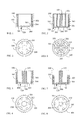
FIG. 1 is a cross sectional view showing the basic structure of the heat dissipater (100), according to the present invention. -
FIG. 2 is a top view ofFIG. 1 . -
FIG. 3 is a cross sectional view illustrating the cup-shaped structure formed in the heat dissipater(100) opposite to the installation location of the electric luminous body (200) being formed with a single annular cup-shaped inner recessed structure, according to the present invention. -
FIG. 4 is a top view ofFIG. 3 . -
FIG. 5 is a cross sectional view illustrating the cup-shaped structure formed in the heat dissipater(100) opposite to the installation location of the electric luminous body (200) being formed with a multiple annular cup-shaped inner recessed structure, according to the present invention. -
FIG. 6 is a top view ofFIG. 5 . -
FIG. 7 is a cross sectional view of the first embodiment of the present invention illustrating the cup-shaped structure formed in the heat dissipater (100) opposite to the installation location of the electric luminous body (200) being formed with a single annular cup-shaped inner recessed structure and a stepped structure having the higher central column (103) and the lower outer periphery. -
FIG. 8 is a top view ofFIG. 7 . -
FIG. 9 is another cross sectional view of the second embodiment of the present invention illustrating the cup-shaped structure formed in the heat dissipater (100) opposite to the installation location of the electric luminous body (200) being formed with a single annular cup-shaped inner recessed structure and a stepped structure having the lower central column (103) and the higher outer periphery. -
FIG. 10 is a top view ofFIG. 9 . -
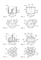
FIG. 11 is one another cross sectional view of the third embodiment of the present invention illustrating the cup-shaped structure formed in the heat dissipater (100) opposite to the installation location of the electric luminous body (200) being formed with a multiple annular cup-shaped inner recessed structure and a multiple stepped structure having the higher central column (103) and the lower multiple annular outer periphery. -
FIG. 12 is a top view ofFIG. 11 . -
FIG. 13 is a schematic lateral view of the first embodiment of the present invention illustrating the upper periphery of the cup-shaped structure formed in the heat dissipater (100) opposite to the installation location of the electric luminous body (200) being formed with a crown-like tooth notch (105) and formed with a central column (103). -
FIG. 14 is a top view ofFIG. 13 . -
FIG. 15 is another schematic lateral view of the second embodiment of the present invention illustrating the upper periphery of the cup-shaped structure formed in the heat dissipation member (100) opposite to the installation location of the electric-powered light emitting unit (200) being formed with multiple crown-like tooth notch (105) and a structure having the higher central column (103) and the lower outer periphery. -
FIG. 16 is a top view ofFIG. 15 . -
FIG. 17 is a schematic view illustrating the heat dissipater (100) opposite to the installation location of the electric luminous body (200) being installed with a conical column member and the cup-shaped structure being formed as a fork-shaped annular structure, according to the present invention. -
FIG. 18 is a top view ofFIG. 17 . -
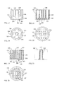
FIG. 19 is a cross sectional view illustrating the interior of the cup-shaped structure formed in the heat dissipater (100) opposite to the installation location of the electric luminous body (200) being installed with a multiple-plate type heat dissipation structure (107), according to the present invention. -
FIG. 20 is a top view ofFIG. 19 . -
FIG. 21 is a cross sectional view illustrating the interior of the cup-shaped structure formed in the heat dissipater (100) opposite to the installation location of the electric luminous body (200) being installed with a multiple-column type heat dissipation structure (108), according to one embodiment of the present invention. -
FIG. 22 is a top view ofFIG. 21 . -
FIG. 23 is a schematic structural view illustrating the central column (103) being composed as a tubular central column with the axially penetrating hole (113), according to the present invention. -
FIG. 24 is a schematic lateral view illustrating the top of the heat dissipater (100) opposite to the installation location of the electric luminous body (200) being additionally installed with a protection net (109), according to one embodiment of the present invention. -
FIG. 25 is a schematic lateral view illustrating the top of the heat dissipater (100) opposite to the installation location of the electric luminous body (200) being installed with a top cover (110), and formed with a ventilation port (112) and a support column (111) served for combining and supporting between the top cover (110) and the heat dissipater (100), according to one embodiment of the present invention. -
FIG. 26 is a schematic lateral view illustrating the support column (111) served for combining and supporting being installed between the top of the heat dissipater (100) opposite to the installation location of the electric luminous body (200) and the top cover (110), and the periphery of the ventilation port (112) being additionally installed with the protection net (109), according to one embodiment of the present invention. -
- 100: Heat dissipater
- 101: Annular surface of heat dissipater
- 103: Central column
- 105: Tooth notch
- 106: Fork-shaped annular structure
- 107: Multiple-plate type heat dissipation structure
- 108: Multiple-column type heat dissipation structure
- 109: Protection net
- 110: Top cover
- 111 : Support column
- 112 : Ventilation port
- 113 : Axially penetrating hole
- 120: Cup bottom surface
- 200: Electric luminous body
- 301: Flow guide hole annularly arranged at the bottom periphery
- 303: Radial flow guide hole
- 304: Inclined flow guide hole at bottom corner
- The present invention provides a novel cup-shaped heat dissipater having flow guide hole for meeting the heat dissipation requirement of an electric luminous body, e.g. the heat dissipation requirement of a light emitting diode (LED) which is adopted as the electric luminous body (200); the outer and/or inner surface of the cup-shaped heat dissipater (100) is served for accommodating the electric luminous body (200), so the heat generated by the electric luminous body (200) can be dissipated to the exterior from the surface of the heat dissipater (100), and further with the enlarged heat dissipation surface formed in the cup-shaped inner recessed structure of the heat dissipater (100) opposite to the installation location of the electric luminous body (200), the heat can also be directly dissipated through the larger heat dissipation area, furthermore, flow guide holes allowing airflow to pass are formed on the heat dissipater (100), the installation location of flow guide hole includes one or more than one of the followings: (a) annularly installing one or more flow guide holes annularly arranged at the bottom periphery (301), which are leaded to the cup-shaped inner recessed structure, at the periphery of the cup bottom surface (120) of the heat dissipater (100) where the electric luminous body (200) being installed, so with the characteristic of hot ascent/cold descent, the airflow near the cup bottom surface (120) of the heat dissipater (100) flows through the flow guide hole annularly arranged at the bottom periphery (301) and the cup-shaped inner recessed structure for dissipating heat to the exterior; (b) axially installing one or more axially penetrating holes (113) at the center of the cup bottom surface (120) or axially penetrating the central column (103), at the center of the cup bottom surface (120); (c) installing one or more radial flow guide holes (303) in the heat dissipater (100); (d) installing one or more inclined flow guide holes at bottom corner (304) at the annular corner formed between the annular heat dissipater bottom of the heat dissipater (100) and the cup bottom surface (120).
-
FIG. 1 is a cross sectional view showing the basic structure of the heat dissipater (100), according to the present invention; -
FIG. 2 is a top view ofFIG. 1 ;
As shown inFIG. 1 and FIG. 2 , it mainly consists of:- -heat dissipater (100): formed as a circular, oval or polygonal cup-shaped or cup-like structure, made of materials having great heat conductivity and heat dissipation property such as aluminum, copper and ceramic, integrally formed or assembled by plural pieces; including parallel or conical or reverse-conical cup body contours; the surface of one or both of the cup periphery and/or the inner annular surface of the heat dissipater (100) is formed as a planar or wavelike structure or formed as a structure having heat dissipation fins;
the outer and/or inner surface of the cup-shaped heat dissipater is served for accommodating the electric luminous body (200), and furthermore, flow guide holes allowing airflow to pass are formed on the heat dissipater (100), and the installation location of flow guide hole includes one or more than one of the followings: (a) annularly installing one or more flow guide holes annularly arranged at the bottom periphery (301), which are leaded to the cup-shaped inner recessed structure, at the periphery of the cup bottom surface (120) of the heat dissipater (100) where the electric luminous body (200) being installed; (b) axially installing one or more axially penetrating holes (113) at the center of the cup bottom surface (120); (c) installing one or more radial flow guide holes (303) in the heat dissipater (100); (d) installing one or more inclined flow guide holes at bottom corner (304) at the annular corner formed between the annular heat dissipater bottom of the heat dissipater (100) and the cup bottom surface (120).
- -heat dissipater (100): formed as a circular, oval or polygonal cup-shaped or cup-like structure, made of materials having great heat conductivity and heat dissipation property such as aluminum, copper and ceramic, integrally formed or assembled by plural pieces; including parallel or conical or reverse-conical cup body contours; the surface of one or both of the cup periphery and/or the inner annular surface of the heat dissipater (100) is formed as a planar or wavelike structure or formed as a structure having heat dissipation fins;
-
FIG. 3 is a cross sectional view illustrating the cup-shaped structure formed in the heat dissipater (100) opposite to the installation location of the electric luminous body (200) being formed with a single annular cup-shaped inner recessed structure, according to the present invention; -
FIG. 4 is a top view ofFIG. 3 ;
As shown inFIG. 3 and FIG. 4 , it mainly consists of:- -heat dissipater (100): formed as a circular, oval or polygonal cup-shaped or cup-like structure, made of materials having great heat conductivity and heat dissipation property such as aluminum, copper and ceramic, integrally formed or assembled by plural pieces; including parallel or conical or reverse-conical cup body contours; wherein one surface of the heat dissipater (100) is installed with the electric luminous body (200), and the other surface of the heat dissipater (100) is formed with the single cup-shaped inner recessed structure and a central column (103); the surface of one or both of the cup periphery and/or the inner annular surface of the heat dissipater (100) is formed as a planar or wavelike structure or formed as a structure having heat dissipation fins;
the outer and/or inner surface of the cup-shaped heat dissipater is served for accommodating the electric luminous body (200), and furthermore, flow guide holes allowing airflow to pass are formed on the heat dissipater (100), and the installation location of flow guide hole includes one or more than one of the followings: (a) annularly installing one or more flow guide holes annularly arranged at the bottom periphery (301), which are leaded to the cup-shaped inner recessed structure, at the periphery of the cup bottom surface (120) of the heat dissipater (100) where the electric luminous body (200) being installed; (b) axially installing one or more axially penetrating holes (113), which axially penetrate the central column (103) at the center of the cup bottom surface (120) (as shown inFIG. 23 ); (c) installing one or more radial flow guide holes (303) in the heat dissipater (100); (d) installing one or more inclined flow guide holes at bottom corner (304) at the annular corner formed between the annular heat dissipater bottom of the heat dissipater (100) and the cup bottom surface (120).
- -heat dissipater (100): formed as a circular, oval or polygonal cup-shaped or cup-like structure, made of materials having great heat conductivity and heat dissipation property such as aluminum, copper and ceramic, integrally formed or assembled by plural pieces; including parallel or conical or reverse-conical cup body contours; wherein one surface of the heat dissipater (100) is installed with the electric luminous body (200), and the other surface of the heat dissipater (100) is formed with the single cup-shaped inner recessed structure and a central column (103); the surface of one or both of the cup periphery and/or the inner annular surface of the heat dissipater (100) is formed as a planar or wavelike structure or formed as a structure having heat dissipation fins;
-
FIG. 5 is a cross sectional view illustrating the cup-shaped structure formed in the heat dissipater (100) opposite to the installation location of the electric luminous body (200) being formed with a multiple annular cup-shaped inner recessed structure, according to the present invention; -
FIG. 6 is a top view ofFIG. 5 ;
As shown inFIG. 5 and FIG. 6 , it mainly consists of:- -heat dissipater (100): formed as a circular, oval or polygonal cup-shaped or cup-like structure, made of materials having great heat conductivity and heat dissipation property such as aluminum, copper and ceramic, integrally formed or assembled by plural pieces; including parallel or conical or reverse-conical cup body contours; wherein one surface of the heat dissipater (100) is installed with the electric luminous body (200), the other surface of the heat dissipater (100) is formed with two or more cup-shaped inner recessed structures and the central column (103) and two or more layers of annular surfaces of heat dissipater (101); the surface of one or both of the cup periphery and/or the inner annular surface of the heat dissipater (100) is formed as a planar or wavelike structure or formed as a structure having heat dissipation fins;
the outer and/or inner surface of the cup-shaped heat dissipater is served for accommodating the electric luminous body (200), and furthermore, flow guide holes allowing airflow to pass are formed on the heat dissipater (100), and the installation location of flow guide hole includes one or more than one of the followings: (a) annularly installing one or more flow guide holes annularly arranged at the bottom periphery (301), which are leaded to the cup-shaped inner recessed structure, at the periphery of the cup bottom surface (120) of the heat dissipater (100) where the electric luminous body (200) being installed; (b) axially installing one or more axially penetrating holes (113), which axially penetrate the central column (103) at the center of the cup bottom surface (120) (as shown inFIG. 23 ); (c) installing one or more radial flow guide holes (303) in the heat dissipater (100); (d) installing one or more inclined flow guide holes at bottom corner (304) at the annular corner formed between the annular heat dissipater bottom of the heat dissipater (100) and the cup bottom surface (120).
- -heat dissipater (100): formed as a circular, oval or polygonal cup-shaped or cup-like structure, made of materials having great heat conductivity and heat dissipation property such as aluminum, copper and ceramic, integrally formed or assembled by plural pieces; including parallel or conical or reverse-conical cup body contours; wherein one surface of the heat dissipater (100) is installed with the electric luminous body (200), the other surface of the heat dissipater (100) is formed with two or more cup-shaped inner recessed structures and the central column (103) and two or more layers of annular surfaces of heat dissipater (101); the surface of one or both of the cup periphery and/or the inner annular surface of the heat dissipater (100) is formed as a planar or wavelike structure or formed as a structure having heat dissipation fins;
-
FIG. 7 is a cross sectional view of the first embodiment of the present invention illustrating the cup-shaped structure formed in the heat dissipater (100) opposite to the installation location of the electric luminous body (200) being formed with a single annular cup-shaped inner recessed structure and a stepped structure having the higher central column (103) and the lower outer periphery; -
FIG. 8 is a top view ofFIG. 7 ;
As shown inFIG. 7 and FIG. 8 , it mainly consists of:- -heat dissipater (100): formed as a circular, oval or polygonal cup-shaped or cup-like structure, made of materials having great heat conductivity and heat dissipation property such as aluminum, copper and ceramic, integrally formed or assembled by plural pieces; including parallel or conical or reverse-conical cup body contours, wherein one surface of the heat dissipater (100) is installed with the electric luminous body (200), the other surface of the heat dissipater (100) is formed with the single cup-shaped inner recessed structure and a higher central column (103), thereby forming a stepped structure having the higher central column (103) and the lower outer periphery; the surface of one or both of the cup periphery and/or the inner annular surface of the heat dissipater (100) is formed as a planar or wavelike structure or formed as a structure having heat dissipation fins;
the outer and/or inner surface of the cup-shaped heat dissipater is served for accommodating the electric luminous body (200), and furthermore, flow guide holes allowing airflow to pass are formed on the heat dissipater (100), and the installation location of flow guide hole includes one or more than one of the followings: (a) annularly installing one or more flow guide holes annularly arranged at the bottom periphery (301), which are leaded to the cup-shaped inner recessed structure, at the periphery of the cup bottom surface (120) of the heat dissipater (100) where the electric luminous body (200) being installed; (b) axially installing one or more axially penetrating holes (113), which axially penetrate the central column (103), at the center of the cup bottom surface (120) (as shown inFIG. 23 ); (c) installing one or more radial flow guide holes (303) in the heat dissipater (100); (d) installing one or more inclined flow guide holes at bottom corner (304) at the annular corner formed between the annular heat dissipater bottom of the heat dissipater (100) and the cup bottom surface (120).
- -heat dissipater (100): formed as a circular, oval or polygonal cup-shaped or cup-like structure, made of materials having great heat conductivity and heat dissipation property such as aluminum, copper and ceramic, integrally formed or assembled by plural pieces; including parallel or conical or reverse-conical cup body contours, wherein one surface of the heat dissipater (100) is installed with the electric luminous body (200), the other surface of the heat dissipater (100) is formed with the single cup-shaped inner recessed structure and a higher central column (103), thereby forming a stepped structure having the higher central column (103) and the lower outer periphery; the surface of one or both of the cup periphery and/or the inner annular surface of the heat dissipater (100) is formed as a planar or wavelike structure or formed as a structure having heat dissipation fins;
-
FIG. 9 is another cross sectional view of the second embodiment of the present invention illustrating the cup-shaped structure formed in the heat dissipater (100) opposite to the installation location of the electric luminous body (200) being formed with a single annular cup-shaped inner recessed structure and a stepped structure having the lower central column (103) and the higher outer periphery; -
FIG. 10 is a top view ofFIG. 9 ;
As shown inFIG. 9 and FIG. 10 , it mainly consists of:- -heat dissipater (100): formed as a circular, oval or polygonal cup-shaped or cup-like structure, made of materials having great heat conductivity and heat dissipation property such as aluminum, copper and ceramic, integrally formed or assembled by plural pieces; including parallel or conical or reverse-conical cup body contours, wherein one surface of the heat dissipater (100) is installed with the electric luminous body (200), the other surface of the heat dissipater (100) is formed with the single cup-shaped inner recessed structure and a lower central column (103), thereby forming a stepped structure having the lower central column (103) and the higher outer periphery; the surface of one or both of the cup periphery and/or the inner annular surface of the heat dissipater (100) is formed as a planar or wavelike structure or one or both of the inner periphery and the outer periphery is formed with a structure having heat dissipation fins;
the outer and/or inner surface of the cup-shaped heat dissipater is served for accommodating the electric luminous body (200), and furthermore, flow guide holes allowing airflow to pass are formed on the heat dissipater (100), and the installation location of flow guide hole includes one or more than one of the followings: (a) annularly installing one or more flow guide holes annularly arranged at the bottom periphery (301), which are leaded to the cup-shaped inner recessed structure, at the periphery of the cup bottom surface (120) of the heat dissipater (100) where the electric luminous body (200) being installed; (b) axially installing one or more axially penetrating holes (113), which axially penetrate the central column (103), at the center of the cup bottom surface (120) (as shown inFIG. 23 ); (c) installing one or more radial flow guide holes (303) in the heat dissipater (100); (d) installing one or more inclined flow guide holes at bottom corner (304) at the annular corner formed between the annular heat dissipater bottom of the heat dissipater (100) and the cup bottom surface (120).
- -heat dissipater (100): formed as a circular, oval or polygonal cup-shaped or cup-like structure, made of materials having great heat conductivity and heat dissipation property such as aluminum, copper and ceramic, integrally formed or assembled by plural pieces; including parallel or conical or reverse-conical cup body contours, wherein one surface of the heat dissipater (100) is installed with the electric luminous body (200), the other surface of the heat dissipater (100) is formed with the single cup-shaped inner recessed structure and a lower central column (103), thereby forming a stepped structure having the lower central column (103) and the higher outer periphery; the surface of one or both of the cup periphery and/or the inner annular surface of the heat dissipater (100) is formed as a planar or wavelike structure or one or both of the inner periphery and the outer periphery is formed with a structure having heat dissipation fins;
-
FIG. 11 is one another cross sectional view of the third embodiment of the present invention illustrating the cup-shaped structure formed in the heat dissipater (100) opposite to the installation location of the electric luminous body (200) being formed with a multiple annular cup-shaped inner recessed structure and a multiple stepped structure having the higher central column (103) and the lower multiple annular outer periphery; -
FIG. 12 is a top view ofFIG. 11 ;
As shown inFIG. 11 and FIG. 12 , it mainly consists of:- -heat dissipater (100): formed as a circular, oval or polygonal cup-shaped or cup-like structure, made of materials having great heat conductivity and heat dissipation property such as aluminum, copper and ceramic, integrally formed or assembled by plural pieces; including parallel or conical or reverse-conical cup body contours, wherein one surface of the heat dissipater (100) is installed with the electric luminous body (200), the other surface of the heat dissipater (100) is formed with two or more multiple annular cup-shaped inner recessed structures and a central column (103) and two or more layers of annular surfaces of heat dissipater (101), thereby forming a multiple stepped structure having the higher central column (103) and the lower multiple annular outer periphery; the surface of one or both of the cup periphery and/or the inner annular surface of the heat dissipater (100) is formed as a planar or wavelike structure or formed as a structure having heat dissipation fins;
the outer and/or inner surface of the cup-shaped heat dissipater is served for accommodating the electric luminous body (200), and furthermore, flow guide holes allowing airflow to pass are formed on the heat dissipater (100), and the installation location of flow guide hole includes one or more than one of the followings: (a) annularly installing one or more flow guide holes annularly arranged at the bottom periphery (301), which are leaded to the cup-shaped inner recessed structure, at the periphery of the cup bottom surface (120) of the heat dissipater (100) where the electric luminous body (200) being installed; (b) axially installing one or more axially penetrating holes (113), which axially penetrate the central column (103), at the center of the cup bottom surface (120) (as shown inFIG. 23 ); (c) installing one or more radial flow guide holes (303) in the heat dissipater (100); (d) installing one or more inclined flow guide holes at bottom corner (304) at the annular corner formed between the annular heat dissipater bottom of the heat dissipater (100) and the cup bottom surface (120);
the mentioned heat dissipater (100) further includes that the cup-shaped structure formed in the heat dissipater (100) opposite to the installation location of the electric luminous body (200) has two or more cup-shaped inner recessed structures and a central column (103) and two or more layers of annular surfaces of heat dissipater (101), thereby forming a multiple-stepped structure having the higher outer periphery.
- -heat dissipater (100): formed as a circular, oval or polygonal cup-shaped or cup-like structure, made of materials having great heat conductivity and heat dissipation property such as aluminum, copper and ceramic, integrally formed or assembled by plural pieces; including parallel or conical or reverse-conical cup body contours, wherein one surface of the heat dissipater (100) is installed with the electric luminous body (200), the other surface of the heat dissipater (100) is formed with two or more multiple annular cup-shaped inner recessed structures and a central column (103) and two or more layers of annular surfaces of heat dissipater (101), thereby forming a multiple stepped structure having the higher central column (103) and the lower multiple annular outer periphery; the surface of one or both of the cup periphery and/or the inner annular surface of the heat dissipater (100) is formed as a planar or wavelike structure or formed as a structure having heat dissipation fins;
-
FIG. 13 is a schematic lateral view of the first embodiment of the present invention illustrating the upper periphery of the cup-shaped structure formed in the heat dissipater (100) opposite to the installation location of the electric luminous body (200) being formed with a crown-like tooth notch (105) and formed with a central column (103); -
FIG. 14 is a top view ofFIG. 13 ;
As shown inFIG. 13 and FIG. 14 , it mainly consists of:- -heat dissipater (100): formed as a circular, oval or polygonal cup-shaped or cup-like structure, made of materials having great heat conductivity and heat dissipation property such as aluminum, copper and ceramic, integrally formed or assembled by plural pieces; including parallel or conical or reverse-conical cup body contours, wherein one surface of the heat dissipater (100) is installed with the electric luminous body (200), the other surface of the heat dissipater (100) is formed the cup-shaped inner recessed structure having an annular structure formed with crown-like tooth notch (105) at the upper periphery and a central column (103), thereby forming a structure of the central column (103) and the annular structure formed with the crown-like tooth notch (105) at the periphery being at the same or different height; the surface of one or both of the cup periphery and/or the inner annular surface of the heat dissipater (100) is formed as a planar or wavelike structure or formed as a structure having heat dissipation fins;
the outer and/or inner surface of the cup-shaped heat dissipater is served for accommodating the electric luminous body (200), and furthermore, flow guide holes allowing airflow to pass are formed on the heat dissipater (100), and the installation location of flow guide hole includes one or more than one of the followings: (a) annularly installing one or more flow guide holes annularly arranged at the bottom periphery (301), which are leaded to the cup-shaped inner recessed structure, at the periphery of the cup bottom surface (120) of the heat dissipater (100) where the electric luminous body (200) being installed; (b) axially installing one or more axially penetrating holes (113), which axially penetrate the central column (103), at the center of the cup bottom surface (120) (as shown inFIG. 23 ); (c) installing one or more radial flow guide holes (303) in the heat dissipater (100); (d) installing one or more inclined flow guide holes at bottom corner (304) at the annular corner formed between the annular heat dissipater bottom of the heat dissipater (100) and the cup bottom surface (120).
- -heat dissipater (100): formed as a circular, oval or polygonal cup-shaped or cup-like structure, made of materials having great heat conductivity and heat dissipation property such as aluminum, copper and ceramic, integrally formed or assembled by plural pieces; including parallel or conical or reverse-conical cup body contours, wherein one surface of the heat dissipater (100) is installed with the electric luminous body (200), the other surface of the heat dissipater (100) is formed the cup-shaped inner recessed structure having an annular structure formed with crown-like tooth notch (105) at the upper periphery and a central column (103), thereby forming a structure of the central column (103) and the annular structure formed with the crown-like tooth notch (105) at the periphery being at the same or different height; the surface of one or both of the cup periphery and/or the inner annular surface of the heat dissipater (100) is formed as a planar or wavelike structure or formed as a structure having heat dissipation fins;
-
FIG. 15 is another schematic lateral view of the second embodiment of the present invention illustrating the upper periphery of the cup-shaped structure formed in the heat dissipation member (100) opposite to the installation location of the electric-powered light emitting unit (200) being formed with multiple crown-like tooth notch (105) and a structure having the higher central column (103) and the lower outer periphery; -
FIG. 16 is a top view ofFIG. 15 ;
As shown inFIG. 15 and FIG. 16 , it mainly consists of:- -heat dissipater (100): formed as a circular, oval or polygonal cup-shaped or cup-like structure, made of materials having great heat conductivity and heat dissipation property such as aluminum, copper and ceramic, integrally formed or assembled by plural pieces; including parallel or conical or reverse-conical cup body contours, wherein one surface of the heat dissipater (100) is installed with the electric luminous body (200), the other surface of the heat dissipater (100) is formed with the cup-shaped inner recessed structure having the multiple crown-like tooth notch (105) at the upper periphery and a central column (103), thereby forming a multiple annular structure having the higher central column (103) and having the lower crown-like tooth notch (105) at the outer periphery; the surface of one or both of the cup periphery and/or the inner annular surface of the heat dissipater (100) is formed as a planar or wavelike structure or one or both of the inner periphery and the outer periphery is formed as a structure having heat dissipation fins;
the outer and/or inner surface of the cup-shaped heat dissipater is served for accommodating the electric luminous body (200), and furthermore, flow guide holes allowing airflow to pass are formed on the heat dissipater (100), and the installation location of flow guide hole includes one or more than one of the followings: (a) annularly installing one or more flow guide holes annularly arranged at the bottom periphery (301), which are leaded to the cup-shaped inner recessed structure, at the periphery of the cup bottom surface (120) of the heat dissipater (100) where the electric luminous body (200) being installed; (b) axially installing one or more axially penetrating holes (113), which axially penetrate the central column (103), at the center of the cup bottom surface (120) (as shown inFIG. 23 ); (c) installing one or more radial flow guide holes (303) in the heat dissipater (100); (d) installing one or more inclined flow guide holes at bottom corner (304) at the annular corner formed between the annular heat dissipater bottom of the heat dissipater (100) and the cup bottom surface (120);
the mentioned heat dissipater (100) further includes that the upper periphery of the cup-shaped structure formed in the heat dissipater (100) opposite to the installation location of the electric luminous body (200) has multiple crown-like tooth notches (105) and a central column (103), thereby forming a structure having the lower central column (103) and the higher multiple annular structure having the crown-like tooth notches (105) at the outer periphery;
the multiple annular structure of the mentioned multiple crown-like tooth notches (105) is defined as two or more layers.
- -heat dissipater (100): formed as a circular, oval or polygonal cup-shaped or cup-like structure, made of materials having great heat conductivity and heat dissipation property such as aluminum, copper and ceramic, integrally formed or assembled by plural pieces; including parallel or conical or reverse-conical cup body contours, wherein one surface of the heat dissipater (100) is installed with the electric luminous body (200), the other surface of the heat dissipater (100) is formed with the cup-shaped inner recessed structure having the multiple crown-like tooth notch (105) at the upper periphery and a central column (103), thereby forming a multiple annular structure having the higher central column (103) and having the lower crown-like tooth notch (105) at the outer periphery; the surface of one or both of the cup periphery and/or the inner annular surface of the heat dissipater (100) is formed as a planar or wavelike structure or one or both of the inner periphery and the outer periphery is formed as a structure having heat dissipation fins;
-
FIG. 17 is a schematic view illustrating the heat dissipater (100) opposite to the installation location of the electric luminous body (200) being installed with a conical column member and the cup-shaped structure being formed as a fork-shaped annular structure, according to the present invention; -
FIG. 18 is a top view ofFIG. 17 ;
As shown inFIG. 17 and FIG. 18 , it mainly consists of:- -heat dissipater (100): formed as a circular, oval or polygonal cup-shaped or cup-like structure, made of materials having great heat conductivity and heat dissipation property such as aluminum, copper and ceramic, integrally formed or assembled by plural pieces; including parallel or conical or reverse-conical cup body contours, wherein one surface of the heat dissipater (100) is installed with the electric luminous body (200), the other surface of the heat dissipater (100) is formed with the cup-shaped inner recessed structure having the fork-shaped annular structure (106) and the conical central column (103); the surface of one or both of the cup periphery and/or the inner annular surface of the heat dissipater (100) is formed as a planar or wavelike structure or formed as a structure having heat dissipation fins;
the outer and/or inner surface of the cup-shaped heat dissipater is served for accommodating the electric luminous body (200), and furthermore, flow guide holes allowing airflow to pass are formed on the heat dissipater (100), and the installation location of flow guide hole includes one or more than one of the followings: (a) annularly installing one or more flow guide holes annularly arranged at the bottom periphery (301), which are leaded to the cup-shaped inner recessed structure, at the periphery of the cup bottom surface (120) of the heat dissipater (100) where the electric luminous body (200) being installed; (b) axially installing one or more axially penetrating holes (113), which axially penetrate the central column (103), at the center of the cup bottom surface (120) (as shown inFIG. 23 ); (c) installing one or more inclined flow guide holes at bottom corner (304) at the annular corner formed between the annular heat dissipater bottom of the heat dissipater (100) and the cup bottom surface (120).
- -heat dissipater (100): formed as a circular, oval or polygonal cup-shaped or cup-like structure, made of materials having great heat conductivity and heat dissipation property such as aluminum, copper and ceramic, integrally formed or assembled by plural pieces; including parallel or conical or reverse-conical cup body contours, wherein one surface of the heat dissipater (100) is installed with the electric luminous body (200), the other surface of the heat dissipater (100) is formed with the cup-shaped inner recessed structure having the fork-shaped annular structure (106) and the conical central column (103); the surface of one or both of the cup periphery and/or the inner annular surface of the heat dissipater (100) is formed as a planar or wavelike structure or formed as a structure having heat dissipation fins;
-
FIG. 19 is a cross sectional view illustrating the interior of the cup-shaped structure formed in the heat dissipater (100) opposite to the installation location of the electric luminous body (200) being installed with a multiple-plate type heat dissipation structure (107), according to the present invention; -
FIG. 20 is a top view ofFIG. 19 ;
As shown inFIG. 19 and FIG. 20 , it mainly consists of:- -heat dissipater (100): formed as a circular, oval or polygonal cup-shaped or cup-like structure, made of materials having great heat conductivity and heat dissipation property such as aluminum, copper and ceramic, integrally formed or assembled by plural pieces; including parallel or conical or reverse-conical cup body contours, wherein one surface of the heat dissipater (100) is installed with the electric luminous body (200), the other surface of the heat dissipater (100) is formed with the cup-shaped inner recessed structure having the multiple-plate type heat dissipation structure (107) therein; the surface of one or both of the cup periphery and/or the inner annular surface of the heat dissipater (100) is formed as a planar or wavelike structure or formed as a structure having heat dissipation fins;
the outer and/or inner surface of the cup-shaped heat dissipater is served for accommodating the electric luminous body (200), and furthermore, flow guide holes allowing airflow to pass are formed on the heat dissipater (100), and the installation location of flow guide hole includes one or more than one of the followings: (a) annularly installing one or more flow guide holes annularly arranged at the bottom periphery (301), which are leaded to the cup-shaped inner recessed structure, at the periphery of the cup bottom surface (120) of the heat dissipater (100) where the electric luminous body (200) being installed; (b) axially installing one or more axially penetrating holes (113) at the center of the cup bottom surface (120) (as shown inFIG. 23 ); (c) installing one or more radial flow guide holes (303) in the heat dissipater (100); (d) installing one or more inclined flow guide holes at bottom corner (304) at the annular corner formed between the annular heat dissipater bottom of the heat dissipater (100) and the cup bottom surface (120).
- -heat dissipater (100): formed as a circular, oval or polygonal cup-shaped or cup-like structure, made of materials having great heat conductivity and heat dissipation property such as aluminum, copper and ceramic, integrally formed or assembled by plural pieces; including parallel or conical or reverse-conical cup body contours, wherein one surface of the heat dissipater (100) is installed with the electric luminous body (200), the other surface of the heat dissipater (100) is formed with the cup-shaped inner recessed structure having the multiple-plate type heat dissipation structure (107) therein; the surface of one or both of the cup periphery and/or the inner annular surface of the heat dissipater (100) is formed as a planar or wavelike structure or formed as a structure having heat dissipation fins;
-
FIG. 21 is a cross sectional view illustrating the interior of the cup-shaped structure formed in the heat dissipater (100) opposite to the installation location of the electric luminous body (200) being installed with a multiple-column type heat dissipation structure (108), according to one embodiment of the present invention; -
FIG. 22 is a top view ofFIG. 21 ;
As shown inFIG. 21 and FIG. 22 , it mainly consists of:- -heat dissipater (100): formed as a circular, oval or polygonal cup-shaped or cup-like structure, made of materials having great heat conductivity and heat dissipation property such as aluminum, copper and ceramic, integrally formed or assembled by plural pieces; including parallel or conical or reverse-conical cup body contours, wherein one surface of the heat dissipater (100) is installed with the electric luminous body (200), and the other surface of the heat dissipater (100) is formed with the cup-shaped inner recessed structure having the multiple-column type heat dissipation structure (108) therein; the surface of one or both of the cup periphery and/or the inner annular surface of the heat dissipater (100) is formed as a planar or wavelike structure or formed as a structure having heat dissipation fins;
the outer and/or inner surface of the cup-shaped heat dissipater is served for accommodating the electric luminous body (200), and furthermore, flow guide holes allowing airflow to pass are formed on the heat dissipater (100), and the installation location of flow guide hole includes one or more than one of the followings: (a) annularly installing one or more flow guide holes annularly arranged at the bottom periphery (301), which are leaded to the cup-shaped inner recessed structure, at the periphery of the cup bottom surface (120) of the heat dissipater (100) where the electric luminous body (200) being installed; (b) axially installing one or more axially penetrating holes (113) at the center of the cup bottom surface (120) (as shown inFIG. 23 ); (c) installing one or more radial flow guide holes (303) in the heat dissipater (100); (d) installing one or more inclined flow guide holes at bottom corner (304) at the annular corner formed between the annular heat dissipater bottom of the heat dissipater (100) and the cup bottom surface (120).
- -heat dissipater (100): formed as a circular, oval or polygonal cup-shaped or cup-like structure, made of materials having great heat conductivity and heat dissipation property such as aluminum, copper and ceramic, integrally formed or assembled by plural pieces; including parallel or conical or reverse-conical cup body contours, wherein one surface of the heat dissipater (100) is installed with the electric luminous body (200), and the other surface of the heat dissipater (100) is formed with the cup-shaped inner recessed structure having the multiple-column type heat dissipation structure (108) therein; the surface of one or both of the cup periphery and/or the inner annular surface of the heat dissipater (100) is formed as a planar or wavelike structure or formed as a structure having heat dissipation fins;
- According to the cup-shaped heat dissipater having flow guide hole annularly arranged at the bottom periphery and applied in electric luminous body, except being composed of a solid central column, the central column (103) can further be composed of a tubular central column;
-
FIG. 23 is a schematic structural view illustrating the central column (103) being composed as a tubular central column with the axially penetrating hole (113), according to the present invention;
As shown inFIG. 23 , the central column (103) of the present invention is composed of the tubular central column with the axially penetrating hole. -
FIG. 24 is a schematic lateral view illustrating the top of the heat dissipater (100) opposite to the installation location of the electric luminous body (200) being additionally installed with a protection net (109), according to one embodiment of the present invention;
As shown inFIG. 24 , according to one embodiment of the present invention, the top of the heat dissipater (100) opposite to the installation location of the electric luminous body (200) is additionally installed with the protection net (109). -
FIG. 25 is a schematic lateral view illustrating the top of the heat dissipater (100) opposite to the installation location of the electric luminous body (200) being installed with a top cover (110), and formed with a ventilation port (112) and a support column (111) served for combining and supporting between the top cover (110) and the heat dissipater (100), according to one embodiment of the present invention;
As shown inFIG. 25 , according to one embodiment of the present invention, the top of the heat dissipater (100) opposite to the installation location of the electric luminous body (200) being installed with the top cover (110), and formed with the ventilation port (112) and the support column (111) served for combining and supporting between the top cover (110) and the heat dissipater (100). -
FIG. 26 is a schematic lateral view illustrating the support column (111) served for combining and supporting being installed between the top of the heat dissipater (100) opposite to the installation location of the electric luminous body (200) and the top cover (110), and the periphery of the ventilation port (112) being additionally installed with the protection net (109), according to one embodiment of the present invention;
As shown inFIG. 26 , according to one embodiment of the present invention, the support column (111) served for combining and supporting is installed between the top of the heat dissipater (100) opposite to the installation location of the electric luminous body (200) and the top cover (110), and the periphery of the ventilation port (112) is additionally installed with the protection net (109).
The mentioned electric luminous body (200) according to the cup-shaped heat dissipater having flow guide hole annularly arranged at the bottom periphery and applied in electric luminous body can further include being composed of the electric luminous body and optical component and lampshade.
Claims (12)
- A cup-shaped heat dissipater having flow guide hole annularly arranged at the bottom periphery and applied in electric luminous body, which is a cup-shaped heat dissipater having flow guide hole, the outer and/or inner surface of the cup-shaped heat dissipater (100) is served for accommodating the electric luminous body (200), so the heat generated by the electric luminous body (200) can be dissipated to the exterior from the surface of the heat dissipater (100), and further with the enlarged heat dissipation surface formed in the cup-shaped inner recessed structure of the heat dissipater (100) opposite to the installation location of the electric luminous body (200), the heat can also be directly dissipated through the larger heat dissipation area, furthermore, flow guide holes allowing airflow to pass are formed on the heat dissipater (100), and it mainly consists of:- -heat dissipater (100): formed as a circular, oval or polygonal cup-shaped or cup-like structure, made of materials having great heat conductivity and heat dissipation property such as aluminum, copper and ceramic, integrally formed or assembled by plural pieces; including parallel or conical or reverse-conical cup body contours; the surface of one or both of the cup periphery and/or the inner annular surface of the heat dissipater (100) is formed as a planar or wavelike structure or formed as a structure having heat dissipation fins;
the outer and/or inner surface of the cup-shaped heat dissipater is served for accommodating the electric luminous body (200), and furthermore, flow guide holes allowing airflow to pass are formed on the heat dissipater (100), and the installation location of flow guide hole includes one or more than one of the followings: (a) annularly installing one or more flow guide holes annularly arranged at the bottom periphery (301), which are leaded to the cup-shaped inner recessed structure, at the periphery of the cup bottom surface (120) of the heat dissipater (100) where the electric luminous body (200) being installed; (b) axially installing one or more axially penetrating holes (113) at the center of the cup bottom surface (120); (c) installing one or more radial flow guide holes (303) in the heat dissipater (100); (d) installing one or more inclined flow guide holes at bottom corner (304) at the annular corner formed between the annular heat dissipater bottom of the heat dissipater (100) and the cup bottom surface (120). - A cup-shaped heat dissipater having flow guide hole annularly arranged at the bottom periphery and applied in electric luminous body as claimed in claim 1, wherein the cup-shaped structure formed in the heat dissipater (100) opposite to the installation location of the electric luminous body (200) is further formed with a single annular cup-shaped inner recessed structure and it mainly consists of:- -heat dissipater (100): formed as a circular, oval or polygonal cup-shaped or cup-like structure, made of materials having great heat conductivity and heat dissipation property such as aluminum, copper and ceramic, integrally formed or assembled by plural pieces; including parallel or conical or reverse-conical cup body contours; wherein one surface of the heat dissipater (100) is installed with the electric luminous body (200), the other surface of the heat dissipater (100) is formed with the single cup-shaped inner recessed structure and a central column (103); the surface of one or both of the cup periphery and/or the inner annular surface of the heat dissipater (100) is formed as a planar or wavelike structure or formed as a structure having heat dissipation fins;
the outer and/or inner surface of the cup-shaped heat dissipater is served for accommodating the electric luminous body (200), and furthermore, flow guide holes allowing airflow to pass are formed on the heat dissipater (100), and the installation location of flow guide hole includes one or more than one of the followings: (a) annularly installing one or more flow guide holes annularly arranged at the bottom periphery (301), which are leaded to the cup-shaped inner recessed structure, at the periphery of the cup bottom surface (120) of the heat dissipater (100) where the electric luminous body (200) being installed; (b) axially installing one or more axially penetrating holes (113), which axially penetrate the central column (103), at the center of the cup bottom surface (120); (c) installing one or more radial flow guide holes (303) in the heat dissipater (100); (d) installing one or more inclined flow guide holes at bottom corner (304) at the annular corner formed between the annular heat dissipater bottom of the heat dissipater (100) and the cup bottom surface (120). - A cup-shaped heat dissipater having flow guide hole annularly arranged at the bottom periphery and applied in electric luminous body as claimed in claim 2, wherein the cup-shaped structure formed in the heat dissipater (100) opposite to the installation location of the electric luminous body (200) is further formed with a multiple annular cup-shaped inner recessed structure, and it mainly consists of:- -heat dissipater (100): formed as a circular, oval or polygonal cup-shaped or cup-like structure, made of materials having great heat conductivity and heat dissipation property such as aluminum, copper and ceramic, integrally formed or assembled by plural pieces; including parallel or conical or reverse-conical cup body contours; wherein one surface of the heat dissipater (100) is installed with the electric luminous body (200), the other surface of the heat dissipater (100) is formed with two or more cup-shaped inner recessed structures and the central column (103) and two or more layers of annular surfaces of heat dissipater (101); the surface of one or both of the cup periphery and/or the inner annular surface of the heat dissipater (100) is formed as a planar or wavelike structure or formed as a structure having heat dissipation fins;
the outer and/or inner surface of the cup-shaped heat dissipater is served accommodating the electric luminous body (200), and furthermore, flow guide holes allowing airflow to pass are formed on the heat dissipater (100), and the installation location of flow guide hole includes one or more than one of the followings: (a) annularly installing one or more flow guide holes annularly arranged at the bottom periphery (301), which are leaded to the cup-shaped inner recessed structure, at the periphery of the cup bottom surface (120) of the heat dissipater (100) where the electric luminous body (200) being installed; (b) axially installing one or more axially penetrating holes (113), which axially penetrate the central column (103), at the center of the cup bottom surface (120); (c) installing one or more radial flow guide holes (303) in the heat dissipater (100); (d) installing one or more inclined flow guide holes at bottom corner (304) at the annular corner formed between the annular heat dissipater bottom of the heat dissipater (100) and the cup bottom surface (120). - A cup-shaped heat dissipater having flow guide hole annularly arranged at the bottom periphery and applied in electric luminous body as claimed in claim 2, wherein the cup-shaped structure formed in the heat dissipater (100) opposite to the installation location of the electric luminous body (200) is further formed with a single annular cup-shaped inner recessed structure and a stepped structure having the higher central column (103) and the lower outer periphery, and it mainly consists of:- -heat dissipater (100): formed as a circular, oval or polygonal cup-shaped or cup-like structure, made of materials having great heat conductivity and heat dissipation property such as aluminum, copper and ceramic, integrally formed or assembled by plural pieces; including parallel or conical or reverse-conical cup body contours, wherein one surface of the heat dissipater (100) is installed with the electric luminous body (200), the other surface of the heat dissipater (100) is formed with the single cup-shaped inner recessed structure and a higher central column (103), thereby forming a stepped structure having the higher central column (103) and the lower outer periphery; the surface of one or both of the cup periphery and/or the inner annular surface of the heat dissipater (100) is formed as a planar or wavelike structure or formed as a structure having heat dissipation fins;
the outer and/or inner surface of the cup-shaped heat dissipater is served for accommodating the electric luminous body (200), and furthermore, flow guide holes allowing airflow to pass are formed on the heat dissipater (100), and the installation location of flow guide hole includes one or more than one of the followings: (a) annularly installing one or more flow guide holes annularly arranged at the bottom periphery (301), which are leaded to the cup-shaped inner recessed structure, at the periphery of the cup bottom surface (120) of the heat dissipater (100) where the electric luminous body (200) being installed; (b) axially installing one or more axially penetrating holes (113), which axially penetrate the central column (103), at the center of the cup bottom surface (120); (c) installing one or more radial flow guide holes (303) in the heat dissipater (100); (d) installing one or more inclined flow guide holes at bottom corner (304) at the annular corner formed between the annular heat dissipater bottom of the heat dissipater (100) and the cup bottom surface (120). - A cup-shaped heat dissipater having flow guide hole annularly arranged at the bottom periphery and applied in electric luminous body as claimed in claim 2, wherein the cup-shaped structure formed in the heat dissipater (100) opposite to the installation location of the electric luminous body (200) is further formed with a single annular cup-shaped inner recessed structure and a stepped structure having the lower central column (103) and the higher outer periphery, and it mainly consists of:- -heat dissipater (100): formed as a circular, oval or polygonal cup-shaped or cup-like structure, made of materials having great heat conductivity and heat dissipation property such as aluminum, copper and ceramic, integrally formed or assembled by plural pieces; including parallel or conical or reverse-conical cup body contours, wherein one surface of the heat dissipater (100) is installed with the electric luminous body (200), the other surface of the heat dissipater (100) is formed with the single cup-shaped inner recessed structure and a lower central column (103), thereby forming a stepped structure having the lower central column (103) and the higher outer periphery; the surface of one or both of the cup periphery and/or the inner annular surface of the heat dissipater (100) is formed as a planar or wavelike structure or one or both of the inner periphery and the outer periphery is formed with a structure having heat dissipation fins;
the outer and/or inner surface of the cup-shaped heat dissipater is served for accommodating the electric luminous body (200), and furthermore, flow guide holes allowing airflow to pass are formed on the heat dissipater (100), and the installation location of flow guide hole includes one or more than one of the followings: (a) annularly installing one or more flow guide holes annularly arranged at the bottom periphery (301), which are leaded to the cup-shaped inner recessed structure, at the periphery of the cup bottom surface (120) of the heat dissipater (100) where the electric luminous body (200) being installed; (b) axially installing one or more axially penetrating holes (113), which axially penetrate the central column (103), at the center of the cup bottom surface (120); (c) installing one or more radial flow guide holes (303) in the heat dissipater (100); (d) installing one or more inclined flow guide holes at bottom corner (304) at the annular corner formed between the annular heat dissipater bottom of the heat dissipater (100) and the cup bottom surface (120). - A cup-shaped heat dissipater having flow guide hole annularly arranged at the bottom periphery and applied in electric luminous body as claimed in claim 3, wherein the cup-shaped structure formed in the heat dissipater (100) opposite to the installation location of the electric luminous body (200) is further formed with a multiple annular cup-shaped inner recessed structure and a multiple stepped structure having the higher central column (103) and the lower multiple annular outer periphery, and it mainly consists of:- -heat dissipater (100): formed as a circular, oval or polygonal cup-shaped or cup-like structure, made of materials having great heat conductivity and heat dissipation property such as aluminum, copper and ceramic, integrally formed or assembled by plural pieces; including parallel or conical or reverse-conical cup body contours, wherein one surface of the heat dissipater (100) is installed with the electric luminous body (200), the other surface of the heat dissipater (100) is formed with two or more multiple annular cup-shaped inner recessed structures and a central column (103) and two or more layers of annular surfaces of heat dissipater (101), thereby forming a multiple stepped structure having the higher central column (103) and the lower multiple annular outer periphery; the surface of one or both of the cup periphery and/or the inner annular surface of the heat dissipater (100) is formed as a planar or wavelike structure or formed as a structure having heat dissipation fins;
the outer and/or inner surface of the cup-shaped heat dissipater is served for accommodating the electric luminous body (200), and furthermore, flow guide holes allowing airflow to pass are formed on the heat dissipater (100), and the installation location of flow guide hole includes one or more than one of the followings: (a) annularly installing one or more flow guide holes annularly arranged at the bottom periphery (301), which are leaded to the cup-shaped inner recessed structure, at the periphery of the cup bottom surface (120) of the heat dissipater (100) where the electric luminous body (200) being installed; (b) axially installing one or more axially penetrating holes (113), which axially penetrate the central column (103), at the center of the cup bottom surface (120); (c) installing one or more radial flow guide holes (303) in the heat dissipater (100); (d) installing one or more inclined flow guide holes at bottom corner (304) at the annular corner formed between the annular heat dissipater bottom of the heat dissipater (100) and the cup bottom surface (120);
the mentioned heat dissipater (100) further includes that the cup-shaped structure formed in the heat dissipater (100) opposite to the installation location of the electric luminous body (200) has two or more cup-shaped inner recessed structures and a central column (103) and two or more layers of annular surfaces of heat dissipater (101), thereby forming a multiple-stepped structure having the higher outer periphery. - A cup-shaped heat dissipater having flow guide hole annularly arranged at the bottom periphery and applied in electric luminous body as claimed in claim 2, wherein the upper periphery of the cup-shaped structure formed in the heat dissipater (100) opposite to the installation location of the electric luminous body (200) is further formed with a crown-like tooth notch (105) and formed with a central column (103), and it mainly consists of:- -heat dissipater (100): formed as a circular, oval or polygonal cup-shaped or cup-like structure, made of materials having great heat conductivity and heat dissipation property such as aluminum, copper and ceramic, integrally formed or assembled by plural pieces; including parallel or conical or reverse-conical cup body contours, wherein one surface of the heat dissipater (100) is installed with the electric luminous body (200), the other surface of the heat dissipater (100) is formed the cup-shaped inner recessed structure having an annular structure formed with crown-like tooth notch (105) at the upper periphery and a central column (103), thereby forming a structure of the central column (103) and the annular structure formed with the crown-like tooth notch (105) at the periphery being at the same or different height; the surface of one or both of the cup periphery and/or the inner annular surface of the heat dissipater (100) is formed as a planar or wavelike structure or formed as a structure having heat dissipation fins;
the outer and/or inner surface of the cup-shaped heat dissipater is served for accommodating the electric luminous body (200), and furthermore, flow guide holes allowing airflow to pass are formed on the heat dissipater (100), and the installation location of flow guide hole includes one or more than one of the followings: (a) annularly installing one or more flow guide holes annularly arranged at the bottom periphery (301), which are leaded to the cup-shaped inner recessed structure, at the periphery of the cup bottom surface (120) of the heat dissipater (100) where the electric luminous body (200) being installed; (b) axially installing one or more axially penetrating holes (113), which axially penetrate the central column (103), at the center of the cup bottom surface (120); (c) installing one or more radial flow guide holes (303) in the heat dissipater (100); (d) installing one or more inclined flow guide holes at bottom corner (304) at the annular corner formed between the annular heat dissipater bottom of the heat dissipater (100) and the cup bottom surface (120). - A cup-shaped heat dissipater having flow guide hole annularly arranged at the bottom periphery and applied in electric luminous body as claimed in claim 3, wherein the upper periphery of the cup-shaped structure formed in the heat dissipation member (100) opposite to the installation location of the electric-powered light emitting unit (200) is further formed with multiple crown-like tooth notch (105) and a structure having the higher central column (103) and the lower outer periphery, and it mainly consists of:- -heat dissipater (100): formed as a circular, oval or polygonal cup-shaped or cup-like structure, made of materials having great heat conductivity and heat dissipation property such as aluminum, copper and ceramic, integrally formed or assembled by plural pieces; including parallel or conical or reverse-conical cup body contours, wherein one surface of the heat dissipater (100) is installed with the electric luminous body (200), the other surface of the heat dissipater (100) is formed with the cup-shaped inner recessed structure having the multiple crown-like tooth notch (105) at the upper periphery and a central column (103), thereby forming a multiple annular structure having the higher central column (103) and having the lower crown-like tooth notch (105) at the outer periphery; the surface of one or both of the cup periphery and/or the inner annular surface of the heat dissipater (100) is formed as a planar or wavelike structure or one or both of the inner periphery and the outer periphery is formed as a structure having heat dissipation fins;
the outer and/or inner surface of the cup-shaped heat dissipater is served for accommodating the electric luminous body (200), and furthermore, flow guide holes allowing airflow to pass are formed on the heat dissipater (100), and the installation location of flow guide hole includes one or more than one of the followings: (a) annularly installing one or more flow guide holes annularly arranged at the bottom periphery (301), which are leaded to the cup-shaped inner recessed structure, at the periphery of the cup bottom surface (120) of the heat dissipater (100) where the electric luminous body (200) being installed; (b) axially installing one or more axially penetrating holes (113), which axially penetrate the central column (103), at the center of the cup bottom surface (120); (c) installing one or more radial flow guide holes (303) in the heat dissipater (100); (d) installing one or more inclined flow guide holes at bottom corner (304) at the annular corner formed between the annular heat dissipater bottom of the heat dissipater (100) and the cup bottom surface (120);
the mentioned heat dissipater (100) further includes that the upper periphery of the cup-shaped structure formed in the heat dissipater (100) opposite to the installation location of the electric luminous body (200) has multiple crown-like tooth notches (105) and a central column (103), thereby forming a structure having the lower central column (103) and the higher multiple annular structure having the crown-like tooth notches (105) at the outer periphery;
the multiple annular structure of the mentioned multiple crown-like tooth notches (105) is defined as two or more layers. - A cup-shaped heat dissipater having flow guide hole annularly arranged at the bottom periphery and applied in electric luminous body as claimed in claim 2, wherein the heat dissipater (100) opposite to the installation location of the electric luminous body (200) is further installed with a conical column member and the cup-shaped structure being formed as a fork-shaped annular structure, and it mainly consists of:- -heat dissipater (100): formed as a circular, oval or polygonal cup-shaped or cup-like structure, made of materials having great heat conductivity and heat dissipation property such as aluminum, copper and ceramic, integrally formed or assembled by plural pieces; including parallel or conical or reverse-conical cup body contours, wherein one surface of the heat dissipater (100) is installed with the electric luminous body (200), the other surface of the heat dissipater (100) is formed with the cup-shaped inner recessed structure having the fork-shaped annular structure (106) and the conical central column (103); the surface of one or both of the cup periphery and/or the inner annular surface of the heat dissipater (100) is formed as a planar or wavelike structure or formed as a structure having heat dissipation fins;
the outer and/or inner surface of the cup-shaped heat dissipater is served for accommodating the electric luminous body (200), and furthermore, flow guide holes allowing airflow to pass are formed on the heat dissipater (100), and the installation location of flow guide hole includes one or more than one of the followings: (a) annularly installing one or more flow guide holes annularly arranged at the bottom periphery (301), which are leaded to the cup-shaped inner recessed structure, at the periphery of the cup bottom surface (120) of the heat dissipater (100) where the electric luminous body (200) being installed; (b) axially installing one or more axially penetrating holes (113), which axially penetrate the central column (103), at the center of the cup bottom surface (120); (c) installing one or more inclined flow guide holes at bottom corner (304) at the annular corner formed between the annular heat dissipater bottom of the heat dissipater (100) and the cup bottom surface (120). - A cup-shaped heat dissipater having flow guide hole annularly arranged at the bottom periphery and applied in electric luminous body as claimed in claim 1, wherein the interior of the cup-shaped structure formed in the heat dissipater (100) opposite to the installation location of the electric luminous body (200) is further installed with a multiple-plate type heat dissipation structure (107), and it mainly consists of:- -heat dissipater (100): formed as a circular, oval or polygonal cup-shaped or cup-like structure, made of materials having great heat conductivity and heat dissipation property such as aluminum, copper and ceramic, integrally formed or assembled by plural pieces; including parallel or conical or reverse-conical cup body contours, wherein one surface of the heat dissipater (100) is installed with the electric luminous body (200), the other surface of the heat dissipater (100) is formed with the cup-shaped inner recessed structure having the multiple-plate type heat dissipation structure (107) therein; the surface of one or both of the cup periphery and/or the inner annular surface of the heat dissipater (100) is formed as a planar or wavelike structure or formed as a structure having heat dissipation fins;
the outer and/or inner surface of the cup-shaped heat dissipater is served for accommodating the electric luminous body (200), and furthermore, flow guide holes allowing airflow to pass are formed on the heat dissipater (100), and the installation location of flow guide hole includes one or more than one of the followings: (a) annularly installing one or more flow guide holes annularly arranged at the bottom periphery (301), which are leaded to the cup-shaped inner recessed structure, at the periphery of the cup bottom surface (120) of the heat dissipater (100) where the electric luminous body (200) being installed; (b) axially installing one or more axially penetrating holes (113) at the center of the cup bottom surface (120); (c) installing one or more radial flow guide holes (303) in the heat dissipater (100); (d) installing one or more inclined flow guide holes at bottom corner (304) at the annular corner formed between the annular heat dissipater bottom of the heat dissipater (100) and the cup bottom surface (120). - A cup-shaped heat dissipater having flow guide hole annularly arranged at the bottom periphery and applied in electric luminous body as claimed in claim 1, the interior of the cup-shaped structure formed in the heat dissipater (100) opposite to the installation location of the electric luminous body (200) is further installed with a multiple-column type heat dissipation structure (108), and it mainly consists of:- -heat dissipater (100): formed as a circular, oval or polygonal cup-shaped or cup-like structure, made of materials having great heat conductivity and heat dissipation property such as aluminum, copper and ceramic, integrally formed or assembled by plural pieces; including parallel or conical or reverse-conical cup body contours, wherein one surface of the heat dissipater (100) is installed with the electric luminous body (200), and the other surface of the heat dissipater (100) is formed with the cup-shaped inner recessed structure having the multiple-column type heat dissipation structure (108) therein; the surface of one or both of the cup periphery and/or the inner annular surface of the heat dissipater (100) is formed as a planar or wavelike structure or formed as a structure having heat dissipation fins;
the outer and/or inner surface of the cup-shaped heat dissipater is served for accommodating the electric luminous body (200), and furthermore, flow guide holes allowing airflow to pass are formed on the heat dissipater (100), and the installation location of flow guide hole includes one or more than one of the followings: (a) annularly installing one or more flow guide holes annularly arranged at the bottom periphery (301), which are leaded to the cup-shaped inner recessed structure, at the periphery of the cup bottom surface (120) of the heat dissipater (100) where the electric luminous body (200) being installed; (b) axially installing one or more axially penetrating holes (113) at the center of the cup bottom surface (120); (c) installing one or more radial flow guide holes (303) in the heat dissipater (100); (d) installing one or more inclined flow guide holes at bottom corner (304) at the annular corner formed between the annular heat dissipater bottom of the heat dissipater (100) and the cup bottom surface (120). - A cup-shaped heat dissipater having flow guide hole annularly arranged at the bottom periphery and applied in electric luminous body as claimed in claim 1, wherein includes:(a) the top of the heat dissipater (100) opposite to the installation location of the electric luminous
body (200) is additionally installed with the protection net (109);(b) the top of the heat dissipater (100) opposite to the installation location of the electric luminous body (200) being installed with the top cover (110), and formed with the ventilation port (112) and the support column (111) served for combining and supporting between the top cover (110) and the heat dissipater (100);(c) (a) and (b) are both installed at the same time.
Applications Claiming Priority (1)
| Application Number | Priority Date | Filing Date | Title |
|---|---|---|---|
| US13/554,092 US9140439B2 (en) | 2012-07-20 | 2012-07-20 | Cup-shaped heat dissipater having flow guide hole annularly arranged at the bottom periphery and applied in electric luminous body |
Publications (1)
| Publication Number | Publication Date |
|---|---|
| EP2687776A1 true EP2687776A1 (en) | 2014-01-22 |
Family
ID=48794016
Family Applications (1)
| Application Number | Title | Priority Date | Filing Date |
|---|---|---|---|
| EP13177305.3A Withdrawn EP2687776A1 (en) | 2012-07-20 | 2013-07-19 | Cup-shaped heat dissipater having flow guide hole annularly arranged at the bottom periphery and applied in electric luminous body |
Country Status (5)
| Country | Link |
|---|---|
| US (1) | US9140439B2 (en) |
| EP (1) | EP2687776A1 (en) |
| CN (2) | CN103574556A (en) |
| CA (1) | CA2821235A1 (en) |
| TW (2) | TWM482166U (en) |
Families Citing this family (2)
| Publication number | Priority date | Publication date | Assignee | Title |
|---|---|---|---|---|
| CN111760201B (en) * | 2020-07-04 | 2022-02-15 | 黄艳民 | A kind of medical spectrum therapy instrument |
| CN113854796B (en) * | 2021-09-01 | 2022-11-18 | 江苏大学 | Heat preservation device with adjustable heat conduction rate |
Citations (11)
| Publication number | Priority date | Publication date | Assignee | Title |
|---|---|---|---|---|
| US20070279862A1 (en) * | 2006-06-06 | 2007-12-06 | Jia-Hao Li | Heat-Dissipating Structure For Lamp |
| EP1950491A1 (en) * | 2007-01-26 | 2008-07-30 | Piper Lux S.r.l. | LED spotlight |
| US20090237932A1 (en) * | 2008-03-18 | 2009-09-24 | Pan-Jit International Inc. | Led lighting device having heat convection and heat conduction effects and heat dissipating assembly therefor |
| US20100133578A1 (en) * | 2009-08-04 | 2010-06-03 | Cree Led Lighting Solutions, Inc. | Solid state lighting device with improved heatsink |
| US20100187963A1 (en) * | 2009-01-28 | 2010-07-29 | Guy Vaccaro | Heat Sink for Passive Cooling of a Lamp |
| US20100282446A1 (en) * | 2007-12-28 | 2010-11-11 | Sharp Kabushiki Kaisha | Heat dissipation device and lighting device |
| US20110110095A1 (en) * | 2009-10-09 | 2011-05-12 | Intematix Corporation | Solid-state lamps with passive cooling |
| US20110193463A1 (en) * | 2010-02-05 | 2011-08-11 | Futur-Tec (Hong Kong) Limited | Multi-component led lamp |
| DE102010031293A1 (en) * | 2010-07-13 | 2012-01-19 | Osram Gesellschaft mit beschränkter Haftung | Heat sink for a semiconductor lamp and semiconductor lamp |
| US20120161602A1 (en) * | 2010-12-27 | 2012-06-28 | Foxconn Technology Co., Ltd. | Led bulb |
| US20120176032A1 (en) * | 2011-01-11 | 2012-07-12 | Chu Wei-Chih | Led lamp with improved heat sink |
Family Cites Families (6)
| Publication number | Priority date | Publication date | Assignee | Title |
|---|---|---|---|---|
| US7909481B1 (en) * | 2009-10-06 | 2011-03-22 | IMG Lighting, Inc. | LED lighting device having improved cooling characteristics |
| CN201844380U (en) * | 2010-11-02 | 2011-05-25 | 林志泽 | Heat dissipation structure for LED lamps |
| CN201944611U (en) * | 2011-01-07 | 2011-08-24 | 惠州Tcl照明电器有限公司 | Automatic heat dissipating LED lamp cup |
| CN102221189B (en) * | 2011-06-11 | 2014-04-02 | 东莞勤上光电股份有限公司 | Vertical convection radiator and vertical convection radiating down lamp |
| CN202177077U (en) * | 2011-07-28 | 2012-03-28 | 广东聚科照明股份有限公司 | Upright column type LED (light emitting diode) radiator |
| CN202327758U (en) * | 2011-11-30 | 2012-07-11 | 海洋王(东莞)照明科技有限公司 | A kind of LED light source assembly |
-
2012
- 2012-07-20 US US13/554,092 patent/US9140439B2/en not_active Expired - Fee Related
-
2013
- 2013-07-18 CA CA2821235A patent/CA2821235A1/en not_active Abandoned
- 2013-07-18 TW TW102213576U patent/TWM482166U/en not_active IP Right Cessation
- 2013-07-18 TW TW102125715A patent/TW201411042A/en unknown
- 2013-07-19 EP EP13177305.3A patent/EP2687776A1/en not_active Withdrawn
- 2013-07-19 CN CN201310305787.8A patent/CN103574556A/en active Pending
- 2013-07-19 CN CN201320433350.8U patent/CN203595100U/en not_active Expired - Fee Related
Patent Citations (11)
| Publication number | Priority date | Publication date | Assignee | Title |
|---|---|---|---|---|
| US20070279862A1 (en) * | 2006-06-06 | 2007-12-06 | Jia-Hao Li | Heat-Dissipating Structure For Lamp |
| EP1950491A1 (en) * | 2007-01-26 | 2008-07-30 | Piper Lux S.r.l. | LED spotlight |
| US20100282446A1 (en) * | 2007-12-28 | 2010-11-11 | Sharp Kabushiki Kaisha | Heat dissipation device and lighting device |
| US20090237932A1 (en) * | 2008-03-18 | 2009-09-24 | Pan-Jit International Inc. | Led lighting device having heat convection and heat conduction effects and heat dissipating assembly therefor |
| US20100187963A1 (en) * | 2009-01-28 | 2010-07-29 | Guy Vaccaro | Heat Sink for Passive Cooling of a Lamp |
| US20100133578A1 (en) * | 2009-08-04 | 2010-06-03 | Cree Led Lighting Solutions, Inc. | Solid state lighting device with improved heatsink |
| US20110110095A1 (en) * | 2009-10-09 | 2011-05-12 | Intematix Corporation | Solid-state lamps with passive cooling |
| US20110193463A1 (en) * | 2010-02-05 | 2011-08-11 | Futur-Tec (Hong Kong) Limited | Multi-component led lamp |
| DE102010031293A1 (en) * | 2010-07-13 | 2012-01-19 | Osram Gesellschaft mit beschränkter Haftung | Heat sink for a semiconductor lamp and semiconductor lamp |
| US20120161602A1 (en) * | 2010-12-27 | 2012-06-28 | Foxconn Technology Co., Ltd. | Led bulb |
| US20120176032A1 (en) * | 2011-01-11 | 2012-07-12 | Chu Wei-Chih | Led lamp with improved heat sink |
Also Published As
| Publication number | Publication date |
|---|---|
| CN203595100U (en) | 2014-05-14 |
| US20140022799A1 (en) | 2014-01-23 |
| TW201411042A (en) | 2014-03-16 |
| CA2821235A1 (en) | 2014-01-20 |
| TWM482166U (en) | 2014-07-11 |
| US9140439B2 (en) | 2015-09-22 |
| CN103574556A (en) | 2014-02-12 |
Similar Documents
| Publication | Publication Date | Title |
|---|---|---|
| EP2687780A1 (en) | Cup-shaped heat dissipater having heat conductive rib and flow guide hole and applied in electric luminous body | |
| EP2687778A1 (en) | Heat dissipater having heat conductive rib with interval forming as flow guide hole and applied in electric luminous body | |
| US8227960B2 (en) | LED projector lamp with improved structure of radiation fins | |
| EP2461089A1 (en) | Illumination device with a lamp cap capable of dissipating heat and spreading light | |
| EP2837882A2 (en) | Electric luminous body having heat dissipater with axial and radial air aperture | |
| US8777462B2 (en) | Lamp structure with a heat dissipation space | |
| US20130163247A1 (en) | Lamp base and lamp having the same | |
| US9140439B2 (en) | Cup-shaped heat dissipater having flow guide hole annularly arranged at the bottom periphery and applied in electric luminous body | |
| US20140022802A1 (en) | Cup-shaped heat dissipater having flow guide hole annularly arranged at the bottom periphery and applied in electric luminous body | |
| EP2687777A1 (en) | Cup-shaped heat dissipater having heat conductive rib therein and applied in electric luminous body | |
| US20140233248A1 (en) | Cup-shaped heat dissipation member applicable in electric-powered light emitting unit | |
| US20130235597A1 (en) | Cup-shaped heat dissipation member applicable in electric-powered light emitting unit | |
| EP2687779A1 (en) | Cup-shaped heat dissipation member applicable in electric-powered light emitting unit | |
| US20140021850A1 (en) | Cup-shaped heat dissipater having heat conductive rib therein and applied in electric luminous body | |
| EP2639503A1 (en) | Cup-shaped heat dissipation member applicable in electric-powered light emitting unit | |
| JP3218914U (en) | Lighting tool heat dissipation device | |
| JP5921342B2 (en) | lighting equipment | |
| JP2012021698A (en) | Radiation fin and radiator |
Legal Events
| Date | Code | Title | Description |
|---|---|---|---|
| PUAI | Public reference made under article 153(3) epc to a published international application that has entered the european phase |
Free format text: ORIGINAL CODE: 0009012 |
|
| AK | Designated contracting states |
Kind code of ref document: A1 Designated state(s): AL AT BE BG CH CY CZ DE DK EE ES FI FR GB GR HR HU IE IS IT LI LT LU LV MC MK MT NL NO PL PT RO RS SE SI SK SM TR |
|
| AX | Request for extension of the european patent |
Extension state: BA ME |
|
| 17P | Request for examination filed |
Effective date: 20140722 |
|
| RBV | Designated contracting states (corrected) |
Designated state(s): AL AT BE BG CH CY CZ DE DK EE ES FI FR GB GR HR HU IE IS IT LI LT LU LV MC MK MT NL NO PL PT RO RS SE SI SK SM TR |
|
| 17Q | First examination report despatched |
Effective date: 20140926 |
|
| STAA | Information on the status of an ep patent application or granted ep patent |
Free format text: STATUS: THE APPLICATION IS DEEMED TO BE WITHDRAWN |
|
| 18D | Application deemed to be withdrawn |
Effective date: 20150207 |