EP2687770A1 - Machine lubricating device and oil filter - Google Patents
Machine lubricating device and oil filter Download PDFInfo
- Publication number
- EP2687770A1 EP2687770A1 EP11861449.4A EP11861449A EP2687770A1 EP 2687770 A1 EP2687770 A1 EP 2687770A1 EP 11861449 A EP11861449 A EP 11861449A EP 2687770 A1 EP2687770 A1 EP 2687770A1
- Authority
- EP
- European Patent Office
- Prior art keywords
- oil
- engine
- oil filter
- hydrotalcite
- lubrication apparatus
- Prior art date
- Legal status (The legal status is an assumption and is not a legal conclusion. Google has not performed a legal analysis and makes no representation as to the accuracy of the status listed.)
- Withdrawn
Links
- 230000001050 lubricating effect Effects 0.000 title 1
- 238000005461 lubrication Methods 0.000 claims abstract description 34
- 239000000126 substance Substances 0.000 claims abstract description 32
- 238000006243 chemical reaction Methods 0.000 claims abstract description 28
- 150000001875 compounds Chemical class 0.000 claims abstract description 26
- 238000002485 combustion reaction Methods 0.000 claims abstract description 16
- 230000015556 catabolic process Effects 0.000 claims description 35
- 238000006731 degradation reaction Methods 0.000 claims description 35
- 239000003921 oil Substances 0.000 description 186
- GDVKFRBCXAPAQJ-UHFFFAOYSA-A dialuminum;hexamagnesium;carbonate;hexadecahydroxide Chemical compound [OH-].[OH-].[OH-].[OH-].[OH-].[OH-].[OH-].[OH-].[OH-].[OH-].[OH-].[OH-].[OH-].[OH-].[OH-].[OH-].[Mg+2].[Mg+2].[Mg+2].[Mg+2].[Mg+2].[Mg+2].[Al+3].[Al+3].[O-]C([O-])=O GDVKFRBCXAPAQJ-UHFFFAOYSA-A 0.000 description 38
- 229960001545 hydrotalcite Drugs 0.000 description 38
- 229910001701 hydrotalcite Inorganic materials 0.000 description 38
- 239000003456 ion exchange resin Substances 0.000 description 28
- 229920003303 ion-exchange polymer Polymers 0.000 description 28
- NWUYHJFMYQTDRP-UHFFFAOYSA-N 1,2-bis(ethenyl)benzene;1-ethenyl-2-ethylbenzene;styrene Chemical compound C=CC1=CC=CC=C1.CCC1=CC=CC=C1C=C.C=CC1=CC=CC=C1C=C NWUYHJFMYQTDRP-UHFFFAOYSA-N 0.000 description 27
- 229910052751 metal Inorganic materials 0.000 description 22
- 239000002184 metal Substances 0.000 description 22
- 150000002500 ions Chemical class 0.000 description 16
- 239000007789 gas Substances 0.000 description 15
- 239000002245 particle Substances 0.000 description 9
- 239000002253 acid Substances 0.000 description 8
- 238000005342 ion exchange Methods 0.000 description 8
- 239000010802 sludge Substances 0.000 description 7
- -1 that is Substances 0.000 description 7
- 238000001914 filtration Methods 0.000 description 5
- 229910017604 nitric acid Inorganic materials 0.000 description 5
- XLYOFNOQVPJJNP-UHFFFAOYSA-N water Substances O XLYOFNOQVPJJNP-UHFFFAOYSA-N 0.000 description 5
- 238000001514 detection method Methods 0.000 description 3
- 230000000694 effects Effects 0.000 description 3
- 238000002474 experimental method Methods 0.000 description 3
- 239000000446 fuel Substances 0.000 description 3
- 239000010705 motor oil Substances 0.000 description 3
- 239000002243 precursor Substances 0.000 description 3
- QAOWNCQODCNURD-UHFFFAOYSA-L Sulfate Chemical compound [O-]S([O-])(=O)=O QAOWNCQODCNURD-UHFFFAOYSA-L 0.000 description 2
- QAOWNCQODCNURD-UHFFFAOYSA-N Sulfuric acid Chemical compound OS(O)(=O)=O QAOWNCQODCNURD-UHFFFAOYSA-N 0.000 description 2
- 229910052787 antimony Inorganic materials 0.000 description 2
- WATWJIUSRGPENY-UHFFFAOYSA-N antimony atom Chemical compound [Sb] WATWJIUSRGPENY-UHFFFAOYSA-N 0.000 description 2
- 238000010586 diagram Methods 0.000 description 2
- 229930195733 hydrocarbon Natural products 0.000 description 2
- 150000002430 hydrocarbons Chemical class 0.000 description 2
- 238000002347 injection Methods 0.000 description 2
- 239000007924 injection Substances 0.000 description 2
- 229910001410 inorganic ion Inorganic materials 0.000 description 2
- 229910001425 magnesium ion Inorganic materials 0.000 description 2
- 239000000463 material Substances 0.000 description 2
- BDAGIHXWWSANSR-UHFFFAOYSA-N methanoic acid Natural products OC=O BDAGIHXWWSANSR-UHFFFAOYSA-N 0.000 description 2
- 230000004048 modification Effects 0.000 description 2
- 238000012986 modification Methods 0.000 description 2
- 230000001629 suppression Effects 0.000 description 2
- 238000011144 upstream manufacturing Methods 0.000 description 2
- IVORCBKUUYGUOL-UHFFFAOYSA-N 1-ethynyl-2,4-dimethoxybenzene Chemical compound COC1=CC=C(C#C)C(OC)=C1 IVORCBKUUYGUOL-UHFFFAOYSA-N 0.000 description 1
- QTBSBXVTEAMEQO-UHFFFAOYSA-M Acetate Chemical compound CC([O-])=O QTBSBXVTEAMEQO-UHFFFAOYSA-M 0.000 description 1
- 239000004215 Carbon black (E152) Substances 0.000 description 1
- 229910020038 Mg6Al2 Inorganic materials 0.000 description 1
- GRYLNZFGIOXLOG-UHFFFAOYSA-N Nitric acid Chemical compound O[N+]([O-])=O GRYLNZFGIOXLOG-UHFFFAOYSA-N 0.000 description 1
- 229910021536 Zeolite Inorganic materials 0.000 description 1
- 238000005299 abrasion Methods 0.000 description 1
- 238000009825 accumulation Methods 0.000 description 1
- 150000001450 anions Chemical class 0.000 description 1
- 239000003054 catalyst Substances 0.000 description 1
- 230000008859 change Effects 0.000 description 1
- 238000004891 communication Methods 0.000 description 1
- 230000006835 compression Effects 0.000 description 1
- 238000007906 compression Methods 0.000 description 1
- 238000009833 condensation Methods 0.000 description 1
- 230000005494 condensation Effects 0.000 description 1
- 238000001816 cooling Methods 0.000 description 1
- 230000006866 deterioration Effects 0.000 description 1
- HNPSIPDUKPIQMN-UHFFFAOYSA-N dioxosilane;oxo(oxoalumanyloxy)alumane Chemical compound O=[Si]=O.O=[Al]O[Al]=O HNPSIPDUKPIQMN-UHFFFAOYSA-N 0.000 description 1
- 238000010828 elution Methods 0.000 description 1
- 238000005516 engineering process Methods 0.000 description 1
- 235000019253 formic acid Nutrition 0.000 description 1
- 238000009434 installation Methods 0.000 description 1
- JEIPFZHSYJVQDO-UHFFFAOYSA-N iron(III) oxide Inorganic materials O=[Fe]O[Fe]=O JEIPFZHSYJVQDO-UHFFFAOYSA-N 0.000 description 1
- 239000010687 lubricating oil Substances 0.000 description 1
- 238000000034 method Methods 0.000 description 1
- 239000000203 mixture Substances 0.000 description 1
- 230000008569 process Effects 0.000 description 1
- 238000000926 separation method Methods 0.000 description 1
- LLZRNZOLAXHGLL-UHFFFAOYSA-J titanic acid Chemical compound O[Ti](O)(O)O LLZRNZOLAXHGLL-UHFFFAOYSA-J 0.000 description 1
- JUWGUJSXVOBPHP-UHFFFAOYSA-B titanium(4+);tetraphosphate Chemical compound [Ti+4].[Ti+4].[Ti+4].[O-]P([O-])([O-])=O.[O-]P([O-])([O-])=O.[O-]P([O-])([O-])=O.[O-]P([O-])([O-])=O JUWGUJSXVOBPHP-UHFFFAOYSA-B 0.000 description 1
- 239000010457 zeolite Substances 0.000 description 1
- 229910000166 zirconium phosphate Inorganic materials 0.000 description 1
- LEHFSLREWWMLPU-UHFFFAOYSA-B zirconium(4+);tetraphosphate Chemical compound [Zr+4].[Zr+4].[Zr+4].[O-]P([O-])([O-])=O.[O-]P([O-])([O-])=O.[O-]P([O-])([O-])=O.[O-]P([O-])([O-])=O LEHFSLREWWMLPU-UHFFFAOYSA-B 0.000 description 1
Images



Classifications
-
- B—PERFORMING OPERATIONS; TRANSPORTING
- B01—PHYSICAL OR CHEMICAL PROCESSES OR APPARATUS IN GENERAL
- B01D—SEPARATION
- B01D35/00—Filtering devices having features not specifically covered by groups B01D24/00 - B01D33/00, or for applications not specifically covered by groups B01D24/00 - B01D33/00; Auxiliary devices for filtration; Filter housing constructions
- B01D35/005—Filters specially adapted for use in internal-combustion engine lubrication or fuel systems
-
- F—MECHANICAL ENGINEERING; LIGHTING; HEATING; WEAPONS; BLASTING
- F01—MACHINES OR ENGINES IN GENERAL; ENGINE PLANTS IN GENERAL; STEAM ENGINES
- F01M—LUBRICATING OF MACHINES OR ENGINES IN GENERAL; LUBRICATING INTERNAL COMBUSTION ENGINES; CRANKCASE VENTILATING
- F01M1/00—Pressure lubrication
- F01M1/10—Lubricating systems characterised by the provision therein of lubricant venting or purifying means, e.g. of filters
-
- B—PERFORMING OPERATIONS; TRANSPORTING
- B01—PHYSICAL OR CHEMICAL PROCESSES OR APPARATUS IN GENERAL
- B01J—CHEMICAL OR PHYSICAL PROCESSES, e.g. CATALYSIS OR COLLOID CHEMISTRY; THEIR RELEVANT APPARATUS
- B01J39/00—Cation exchange; Use of material as cation exchangers; Treatment of material for improving the cation exchange properties
- B01J39/08—Use of material as cation exchangers; Treatment of material for improving the cation exchange properties
- B01J39/10—Oxides or hydroxides
-
- B—PERFORMING OPERATIONS; TRANSPORTING
- B01—PHYSICAL OR CHEMICAL PROCESSES OR APPARATUS IN GENERAL
- B01J—CHEMICAL OR PHYSICAL PROCESSES, e.g. CATALYSIS OR COLLOID CHEMISTRY; THEIR RELEVANT APPARATUS
- B01J39/00—Cation exchange; Use of material as cation exchangers; Treatment of material for improving the cation exchange properties
- B01J39/08—Use of material as cation exchangers; Treatment of material for improving the cation exchange properties
- B01J39/14—Base exchange silicates, e.g. zeolites
-
- B—PERFORMING OPERATIONS; TRANSPORTING
- B01—PHYSICAL OR CHEMICAL PROCESSES OR APPARATUS IN GENERAL
- B01J—CHEMICAL OR PHYSICAL PROCESSES, e.g. CATALYSIS OR COLLOID CHEMISTRY; THEIR RELEVANT APPARATUS
- B01J39/00—Cation exchange; Use of material as cation exchangers; Treatment of material for improving the cation exchange properties
- B01J39/08—Use of material as cation exchangers; Treatment of material for improving the cation exchange properties
- B01J39/16—Organic material
-
- B—PERFORMING OPERATIONS; TRANSPORTING
- B01—PHYSICAL OR CHEMICAL PROCESSES OR APPARATUS IN GENERAL
- B01J—CHEMICAL OR PHYSICAL PROCESSES, e.g. CATALYSIS OR COLLOID CHEMISTRY; THEIR RELEVANT APPARATUS
- B01J41/00—Anion exchange; Use of material as anion exchangers; Treatment of material for improving the anion exchange properties
- B01J41/02—Processes using inorganic exchangers
-
- B—PERFORMING OPERATIONS; TRANSPORTING
- B01—PHYSICAL OR CHEMICAL PROCESSES OR APPARATUS IN GENERAL
- B01J—CHEMICAL OR PHYSICAL PROCESSES, e.g. CATALYSIS OR COLLOID CHEMISTRY; THEIR RELEVANT APPARATUS
- B01J41/00—Anion exchange; Use of material as anion exchangers; Treatment of material for improving the anion exchange properties
- B01J41/08—Use of material as anion exchangers; Treatment of material for improving the anion exchange properties
- B01J41/10—Inorganic material
-
- F—MECHANICAL ENGINEERING; LIGHTING; HEATING; WEAPONS; BLASTING
- F01—MACHINES OR ENGINES IN GENERAL; ENGINE PLANTS IN GENERAL; STEAM ENGINES
- F01M—LUBRICATING OF MACHINES OR ENGINES IN GENERAL; LUBRICATING INTERNAL COMBUSTION ENGINES; CRANKCASE VENTILATING
- F01M11/00—Component parts, details or accessories, not provided for in, or of interest apart from, groups F01M1/00 - F01M9/00
- F01M11/03—Mounting or connecting of lubricant purifying means relative to the machine or engine; Details of lubricant purifying means
-
- F—MECHANICAL ENGINEERING; LIGHTING; HEATING; WEAPONS; BLASTING
- F01—MACHINES OR ENGINES IN GENERAL; ENGINE PLANTS IN GENERAL; STEAM ENGINES
- F01M—LUBRICATING OF MACHINES OR ENGINES IN GENERAL; LUBRICATING INTERNAL COMBUSTION ENGINES; CRANKCASE VENTILATING
- F01M9/00—Lubrication means having pertinent characteristics not provided for in, or of interest apart from, groups F01M1/00 - F01M7/00
- F01M9/02—Lubrication means having pertinent characteristics not provided for in, or of interest apart from, groups F01M1/00 - F01M7/00 having means for introducing additives to lubricant
-
- F—MECHANICAL ENGINEERING; LIGHTING; HEATING; WEAPONS; BLASTING
- F01—MACHINES OR ENGINES IN GENERAL; ENGINE PLANTS IN GENERAL; STEAM ENGINES
- F01M—LUBRICATING OF MACHINES OR ENGINES IN GENERAL; LUBRICATING INTERNAL COMBUSTION ENGINES; CRANKCASE VENTILATING
- F01M1/00—Pressure lubrication
- F01M1/10—Lubricating systems characterised by the provision therein of lubricant venting or purifying means, e.g. of filters
- F01M2001/1007—Lubricating systems characterised by the provision therein of lubricant venting or purifying means, e.g. of filters characterised by the purification means combined with other functions
- F01M2001/1014—Lubricating systems characterised by the provision therein of lubricant venting or purifying means, e.g. of filters characterised by the purification means combined with other functions comprising supply of additives
Definitions
- the present invention relates to a lubrication apparatus to supply oil to one or more supply portions in a machine such as an internal combustion engine, and an oil filter that can be applied to the lubrication apparatus.
- An internal combustion engine is provided with a lubrication apparatus configured to supply oil to supply portions such as a sliding portion and the like therein.
- a lubrication apparatus configured to supply oil to supply portions such as a sliding portion and the like therein.
- oil filters can be used in such a lubrication apparatus.
- Patent Literature 1 discloses a filtering element for a bypass oil filter in an internal combustion engine. According to the description of Patent Literature 1, this filtering element includes a hydrotalcites compound that is expressed according to the following (1) formula. Mg x Al 2 (OH) 6+2x-2y (CO 3 ) y ⁇ mH 2 O (1), where x and y are integral numbers that meet a condition of 3 ⁇ x ⁇ 20 and 0 ⁇ y ⁇ 2, and m indicates an integral number.
- an object of the present invention is to, in a case of using hydrotalcites compounds in a lubrication apparatus in a machine such as an internal combustion engine, suppress degradation of oil due to the hydrotalcites compound.
- a first aspect of the present invention provides a lubrication apparatus in a machine comprising a hydrotalcites compound that is provided in an oil passage, and a reaction substance that is provided in the oil passage and has a function of trapping a metallic component separated from the hydrotalcites compound.
- the reaction substance preferably has a function of trapping a positive ion, which is separated from the hydrotalicites compound, as the metallic component.
- the lubrication apparatus in the machine according to the present invention further comprises an output means for outputting a signal corresponding to an amount of the metallic component in the oil, and a degradation determining means for determining degradation of the oil based upon the output of the output means.
- the lubrication apparatus in the machine according to the present invention can include an oil filter that is provided in the oil passage, wherein the oil filter may include the hydrotalcites compound and the reaction substance.
- the lubrication apparatus in the machine according to the present invention can include two oil filters that are provided in the oil passage, wherein one of the two oil filters may include at least the hydrotalcites compound, and the other of the two oil filters may include at least the reaction substance.
- the machine preferably is an internal combustion engine.
- a second aspect of the present invention provides an oil filter comprising a hydrotalcites compound that is provided in an oil passage, and a reaction substance that is provided in the oil passage and has a function of trapping a metallic component separated from the hydrotalcites compound.
- the reaction substance preferably has a function of trapping a positive ion, which is separated from the hydrotalcites compound, as the metallic component.
- Fig. 1 shows a schematic diagram of an internal combustion engine 10 (hereinafter, called an engine) to which the first embodiment is applied.
- an engine 10 is an engine of an in-line four-cylinder type, but an engine to which the present invention is applied may be an engine of not only any cylinder number and any cylinder arrangement type, but also a spark ignition type engine or a compression ignition type engine.
- the engine 10 includes a cylinder block 12 provided integrally with a crank case, a cylinder head 14, a head cover 16 for covering the cylinder head 14 from above, and an oil pan 18.
- a lubrication apparatus 26 in the engine 10 is configured to supply oil to one or supply portions in the engine 10.
- the one or more supply portions include herein a plurality of supply portions including a plurality of sliding portions in the engine 10.
- a part of the lubrication apparatus 26 is schematically illustrated in Fig. 1
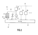
- a part of the lubrication apparatus 26 is further schematically illustrated in Fig. 2 .
- the engine 10 and the lubrication apparatus 26 will be explained with reference to Fig. 1 and Fig. 2 .
- the lubrication apparatus 26 has a strainer (not shown) and an oil pump 28, and oil that is reserved in the oil pan 18 as an oil reservoir section is pumped up (suctioned) by the oil pump 28 via the strainer.
- the pump 28 is configured to be mechanically driven by receiving power from a cam shaft or a crank shaft following an operation of the engine 10, and is provided with a relief valve 29 to release the oil to a side of the oil pan 18 at a high hydraulic pressure.
- the oil pumped up by the oil pump 28 as described above is supplied via an oil filter 30 to a plurality of portions 34a, 34b ... in the engine 10 through an oil passage 32 (including a plurality of oil paths corresponding to the respective supply portions) that is formed in the engine 10.
- the portions 34a, 34b ... include, for example, cam shaft journals, crank journals, connecting rods, pistons and the like.
- the lubricating oil that is, the oil supplied to the plurality of portions in this way finally returns back to the oil pan 18 by its self-weight.
- the oil is thus circulated in the lubrication apparatus 26.
- a space in which the oil can thus flow in the engine 10 is herein called "oil passage".
- An oil return passage 36 is formed in the cylinder block 12 and the cylinder head 14 in such a manner as to establish communication between an inside of the head cover 16 or an inside of the cylinder head 14 and an inside of the crank case, that is, an inside of the oil pan 18.
- the oil return passage 36 is a passage for returning (dropping), for example, the oil having finished the lubrication of a valve train from the cylinder head 14 toward the inside of the oil pan 18.
- an air passage 38 is formed to establish connection between the inside of the crank case, that is, the inside of the oil pan 18 and the inside of the head cover 16 or the inside of the cylinder head 14.
- the air passage 38 also has a function of upward moving the blow-by gas in the crank case toward the inside of the head cover 16.
- the oil return passage 36 and the air passage 38 can respectively function as oil passages, and can also function as air passages. It should be noted that the number of the oil return passage 36 and the number of the air passage 38 respectively may be set to any number.
- the blow-by gas means a gas that leaks out into the inside of the crank case from a gap between a piston ring of the piston and a cylinder bore of the cylinder block 12.
- This blow-by gas contains a great deal of hydrocarbons and water components. Therefore too many blow-by gases cause earlier degradation of the engine oil or rust of an internal part of the engine.
- the blow-by gas contains the hydrocarbon, it is not preferable environmentally to release the blow-by gas into an atmosphere as it is. Therefore the engine 10 has a known blow-by gas circulation device (not shown). The blow-by gas is introduced into the head cover 16, and thereafter is forcibly returned back to an intake system by using an intake negative pressure to be supplied into the combustion chamber.
- NOx, SOx, and water components are contained in the blow-by gas.
- heat from the engine is hard to be transmitted to the head cover 16 and the head cover 16 is exposed to outside air at an outer surface thereof to be cooled by cooling wind or the like, condensed water due to dew condensation or the like tends to be easily generated on the inner surface of the head cover 16. Therefore acid substances, for example, nitric acid and sulfuric acid tend to be easily generated particularly in the head cover 16 due to the reaction thereof.
- These acid substances can be mixed with the lubrication oil, that is, the engine oil to accelerate generation, adhesion, and accumulation of the sludge precursor and the sludge in the engine.
- the sludge can be generated due to degradation of oil, and can further cause the degradation of the oil. Therefore suppression of generation or the like of the sludge precursor and the sludge brings in suppression of degradation of the oil.
- an oil degradation suppressing apparatus 40 applied to the lubrication apparatus 26 in the engine 10 has an oil filter 42 for removing such acid substances, that is, acid components from the engine oil.
- the oil filter 42 as a filtering member is provided in a bypass passage 46 that is branched from a main oil passage 44 of the oil passage 32 to be communicated with the inside of the oil pan 18.
- the bypass passage 46 is included in the oil passage 32, and may be called a sub oil passage to the main oil passage 44 for supplying oil to the above-mentioned supply portions 34a, 34b... in the engine 10.
- the oil filter 42 and a part of the bypass passage 46 are drawn outside of an engine body 10'.
- the installation positions of the oil filter 42 and the like are not limited to the positions illustrated in Fig. 1 , and can be changed to various locations.
- the oil filter 42 and the like may be positioned to a portion making contact with an outside of each component in the engine body 10' , to a portion away from the outside thereof or to an inside of each component in the engine body 10'.
- the oil filter 42 is provided to be replaceable.
- the oil filter 42 is preferably positioned in a position of being easy for replacement. It should be noted that the oil filter 42 is replaceable at an appropriate time.
- a first member 48 and a second member 50 are serially arranged in the oil filter 42 in order from the upstream side.
- the oil degradation suppressing apparatus 40 is configured such that the oil can flow in the oil filter 42 by not only the pressure by the oil pump 28 but also by using its self-weight, wherein the first member 48 is positioned upwards in a vertical direction to the second member 50. Therefore the oil that flows into the oil filter 42 goes to the first member 48, the oil that passes through the first member 48 goes to the second member 50, and thereafter, the oil that passes through the second member 50 can flow into the oil pan 18 by its self-weight.
- the first member 48 in the oil filter 42 is configured to adsorb predetermined acid components in the oil.
- the first member 48 includes a support member, and a great number of (a plurality of) hydrotalcite particles supported or accommodated therein.
- hydrotalcite particles are supported in such a manner as to be sandwiched between filteringmembers as a part of the support member, and are further accommodated in a case member as a part of the support member.
- the support member of the case member and the like in the first member 48 is configured such that the oil can appropriately pass through them.
- the support member of the first member 48 may be a net-like bag body, a three-dimensional net-like structure, a porous structure, a cylindrical structure or the like, and a plurality of hydrotalcite particles can be trapped or held in at least one of an inside thereof and clearances thereof.
- one or more hydrotalcites that are supported by such a support member may be a single or a plurality of block bodies integrally solidified at least in the process before use.
- one or more hydrotalcites that are supported by such a support member may be formed in a shape other than the particle.
- the hydrotalcite as a first reaction substance provided in the first member 46 or included therein has a layered structure, and has the characteristic of taking in negative ions, that is, anions between layers of a skeleton portion configured to include metallic components as primary components.
- a hydrotalcite may have a function of taking in, that is, absorbing a new negative ion, and instead, releasing the negative ion that hasbeenheldbetweenlayerssofar. Therefore, the hydrotalcite is an ion exchange body (ion exchange material), and functions as the ion exchange body.
- the hydrotalcite has a function of adsorbing a predetermined ion, that is, an ion component in the oil, particularly an acid component (e.g.
- a nitric acid ion in the oil.
- the hydrotalcite is used for removing a nitric acid ion (NO 3 - ) that can be generated by NOx in the blow-by gas and water, and a sulfate ion (SO 4 2- ) that can be generated by SOx in the blow-by gas and water from the oil.
- the acid component desired to be removed from the oil by the hydrotalcite is not only the nitric acid ion (NO 3 - ) and the sulfate ion (SO 4 2- ) but also, for example, an acetate ion (CH 3 COO - ) that can be generated based upon the blow-by gas and similarly a formic acid ion (HCOO - ) that can be generated based upon the blow-by gas.
- the hydrotalcite in the first member 48 can have a function of adsorbing, that is, trapping at least one component selected from a group containing these ions or a group consisting of these ions.
- hydrotalcites compounds can be contained in the first member 48.
- hydrotalcite "Mg 6 Al 2 (OH)(CO 3 ) 16 “ (hereinafter, called "HT") made by Wako Pure Chemical Industries, Ltd. may be used.
- This hydrotalcite, that is, HT is a layered compound including layers of the skeleton portion configured to include Al and Mg as primary components, and negative ions interposed in a sandwich shape between the layers.
- the second member 50 in the oil filter 42 is configured to trap a predetermined component in the oil.
- the second member 50 includes a support member, and a great number of (a plurality of) positive ion exchange resin particles supported or accommodated therein.
- a great number of (a plurality of) positive ion exchange resin particles are accommodated in the case member as the support member.
- the case member of the second member 50 is configured such that the oil can appropriately pass through it.
- the support member of the second member 50 may be a net-like bag body, a three-dimensional net-like structure, a porous structure, a cylindrical structure or the like, and a plurality of positive ion exchange resin particles can be trapped or held in at least one of an inside thereof and clearances thereof.
- one or more positive ion exchange resins that are supported by such a support member may be a single or a plurality of block bodies, or may have various kinds of shapes other than the particle.
- the positive ion exchange resin as a second reaction substance provided in the second member 50 or included therein is an ion exchange body (ion exchange material).
- the positive ion exchange resin used herein has a function of trapping, that is, absorbing a predetermined positive ion (ion component).
- the positive ion exchange resin has a function of trapping a positive ion such as an Al ion (Al 3+ ) and a Mg ion (Mg 2+ ).
- an example of the ion exchange resin that may be used in the second member 50 includes an ion exchange resin of Diaion (registered trademark) series (for example, WK10 or WK11) made by Mitsubishi Chemical Co., Ltd.
- the hydrotalcite has the layer of the skeleton portion configured to include the metallic components as the primary component as described above, and has, for example, the characteristic that the metallic component such as Mg or Al in the layer of the skeleton portion tends to be easily eluted into oil.
- the hydrotalcite to be used is a particle substance having a diameter of approximately 5 to 30 ⁇ m, elution of the metallic component such as Al or Mg into oil tends to be easily generated.
- the metallic components such as Al and Mg that are separated from the hydrotalcite can have an influence on an oil addictive or oil itself to achieve an assisting catalyst function for accelerating the oil degradation. Therefore it is desired to remove the metallic components such as Al and Mg that are the predetermined components due to the hydrotalcite, from the oil or the oil passage 32.
- This metallic component such as Al or Mg can generally exist in the oil as a positive ion.
- the ion exchange resin in the second member 50 provided as described above has the function of trapping or absorbing a positive ion. Therefore Al and Mg that are separated from and due to the hydrotalcite of the first member 48 can be trapped by the positive ion exchange resin in the second member 50. Accordingly the oil degradation based upon the hydrotalcite use can be suppressed, and as a result, it is possible to enhance the effect of suppressing the oil deterioration due to the hydrotalcite.
- the lateral axis in Fig. 3 indicates a travel distance (km) of a vehicle equipped with the engine 10, and the vertical axis indicates a metal amount (mol) in the oil of the lubrication apparatus 26.
- the above-mentioned HT was used as the hydrotalcite, and the ion exchange resin of Diaion (registered trademark) series made by Mitsubishi Chemical Co., Ltd. was used as the positive ion exchange resin.
- a line L1 in Fig. 3 shows a relation between a travel distance and a metal amount in a case where the oil filter 42 is not provided, that is, in a case where the hydrotalcite and the positive ion exchange resin are not provided.
- a line L2 in Fig. 3 shows a relation between a travel distance and a metal amount in a case where the oil filter 42 with the second member 50 removed is provided, that is, in a case where only the hydrotalcite is provided in the oil passage.
- a line L3 in Fig. 3 shows a relation between a travel distance and a metal amount in a case where the oil filter 42 is provided, that is, in a case where both the hydrotalcite and the positive ion exchange resin are provided in the oil passage.
- the hydrotalcite was arranged in the oil passage, thereby increasing the metal amount in the oil. This is estimated because the metallic component such as Al or Mg was eluted into the oil from the hydrotalcite.
- the hydrotalcite and the reaction substance that is the positive ion exchange resin respectively are supported by members different from each other for separation.
- the present invention allows them to be combined or mixed for use.
- the first member 48 is arranged upward in the vertical direction of the second member 50.
- the oil filter 42 is formed as a cylindrical structure including an inner cylinder and an outer cylinder, wherein the hydrotalcite can be accommodated in one of the inner cylinder and the outer cylinder, and the reaction substance such as the positive ion exchange resin can be accommodated in the other cylinder.
- one member where the hydrotalcite is accommodated is preferably positioned upstream of the other member where the reaction substance such as the positive ion exchange resin is accommodated, but may be positioned downstream of the other member.
- the hydrotaocite and the reaction substance which is the ion exchange resin are incorporated in the single oil filter, but respectively may be accommodated in different filtering members. That is, two oil filters that are provided in the oil passage are used, wherein one of the two oil filters may include at least the hydrotalcites compound, and the other of the two oil filters may include the reaction substance, that is, the second reaction substance.
- the hydrotalcite and the second reaction substance may be arranged to be adjacent to each other, but may be arranged to be in a position far away from each other, for example, in different oil return passages.
- the oil that is circulated and supplied by the oil pump 28 is branched to an oil filter 30 that is a full flow filter and the oil filter 42 that is a bypass filter.
- the oil filter 42 including the hydrotalcite and the ion exchange resin may be provided in the oil passage 32 as a full flow filter.
- the oil filter 42 may be provided to be adjacent to the oil filter 30, or may be incorporated integrally with the oil filter 30.
- both or one of the two oil filters may be used as the full flow filter or the bypass filter.
- the positive ion exchange resin as the second reaction substance is included in the second member 50, but the second reaction substance to be used is not limited to the ion exchange resin, and various kinds of ion exchange bodies may be used as the second reaction substance.
- various kinds of inorganic ion exchange bodies may be used as the second reaction substance.
- the inorganic ion exchange body may include zeolite, crystalline antimony acid, aqueous pentoxide antimony, titanium phosphate, zirconium phosphate, titanium hydroxide, zirconium hydroxide, and the like.
- An engine 100 to which the second embodiment is applied is provided with the same configuration as that of the above-mentioned engine 10, and is further provided with an oil degradation detecting apparatus.
- an explanation will be made primarily of the oil degradation detecting apparatus.
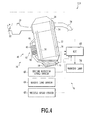
- the engine to which the second embodiment is applied will be explained with reference to Fig. 4 and Fig. 2 , and components identical to those already explained are referred to as identical codes, and the overlapping explanation thereof can be omitted.
- the above-mentioned modification and the like to the first embodiment can likewise be applied to the second embodiment.
- the engine 100 to which the second embodiment is applied is provided with an electronically controlled unit (ECU) 60 that substantially has functions of various kinds of control devices (control means) and various kinds of detecting devices (detecting means) in the engine 100.
- the ECU 60 is configured of a microcomputer including a CPU, a memory device including a ROM and a RAM, an A/D converter, an input interface, an output interface and the like.
- the input interface is connected electrically to various sensors including an engine rotation speed sensor 62 for detecting an engine rotation speed, an engine load sensor 64 for detecting an engine load, a vehicle speed sensor 66 and the like.
- a crank angle sensor may be used as the engine rotation speed sensor 62.
- an air flow meter, an accelerator opening degree sensor or the like may be used as the engine load sensor 64.
- the ECU 60 electrically outputs operation signals (drive signals) to a fuel injection valve, an actuator for the throttle valve 22 and the like from the output interface based upon output (detection signals) from these various sensors such that a smooth drive or operation of the engine 10 can be performed according to preset programs.
- this electronically controlled system for example, the ECU 60 and various kinds of sensors including the engine rotation speed sensor 62, the engine load sensor 64, the vehicle speed sensor 66 and the like are omitted in the explanation in the first embodiment, which are similarly provided also in the engine 10.
- the engine 100 in the second embodiment is further provided with the oil degradation detecting apparatus 70.
- the oil degradation suppressing apparatus 40 including the oil filter 42 to the lubrication apparatus 26 as described above, the degradation of the oil in the lubrication apparatus 26 can be suppressed.
- the oil filter 42 is desirably replaced at appropriate timing. The appropriate timing can be suitably determined by using the oil degradation detecting apparatus 70.
- the oil degradation detecting apparatus 70 includes a permittivity sensor 72 as an output means for outputting a signal in accordance with an amount of metallic components in the oil, and a degradation determining means for determining degradation of the oil based upon the output of the permittivity sensor 72.
- the permittivity sensor 72 is provided in the oil pan 18 in the oil passage 32 herein, but may be provided in the other location in the oil passage 32. It should be noted that various kinds of sensors may be used as the permittivity sensor 72, and, for example, commercial products made by BOSCH Co., commercial products made by Delphi Co. , commercial products made by Kittiwake Co., and the like may be adopted. It should be noted that a sensor other than the permittivity sensor may be used as the output means for outputting a signal in accordance with an amount of metallic components in the oil.
- An amount of metallic components of Al, Mg, Fe and the like in the oil has a proportional relation to the permittivity of oil. Therefore the output from the permittivity sensor 72 has a correlation with the amount of the metallic components in the oil, for example, a metal concentration. Therefore the degradation of the oil can be determined based upon the output from the permittivity sensor 72.
- An output signal from the permittivity sensor 72 is processed as described later by the ECU 60 to which the permittivity sensor 72 is electrically connected.
- the ECU 60 has a function of the degradation determining means for determining degradation of the oil based upon the output signal from the permittivity sensor 72.
- the ECU 60 can light up a warning lamp 74 in such a manner as to let a driver know about the degradation of the oil to prompt replacement of the oil filter 42.
- the warning lamp 74 may be provided on a front panel of a driver's seat or the like.
- Fig. 5 is a flow chart indicating a flow of the degradation determination of the oil.
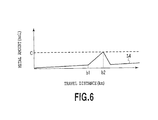
- Fig. 6 is a graph conceptually indicating the experiment result conducted for examining a relation between a travel distance (km) of a vehicle on which the engine 100 provided with the oil filter 42 is mounted and an amount of metallic components in the oil in the lubrication apparatus 26 of the engine 100, that is, a metal amount (mol).
- a value that is equivalent to the metal amount is detected.
- the permittivity is herein detected based upon an output signal from the permittivity sensor 72.
- the amount of the metallic components that is, the metal amount may further be calculated based upon the permittivity.
- the value that is equivalent to the metal amount may be the permittivity or the metal amount in this way, or may be the other value.
- a value of a voltage value, a current value or the like may be used as it is as the value that is equivalent to the metal amount.
- data, a calculation formula or the like for detecting the value that is equivalent to the metal amount is in advance stored in the memory device.
- step S503 it is determined whether or not the value detected at step S501, that is, the detection value is equal to or more than a threshold, that is, a predetermined value a.
- the threshold is in advance defined and stored in the memory device. In a case where the detection value is not equal to or more than the threshold a, at step S503 the negative determination is made.
- Fig. 6 indicates a change in a metal amount in the oil.
- the oil filter 42 sufficiently achieves its function, as already explained by referring to Fig. 3 , since the metal in the oil is trapped by the positive ion exchange resin in the second member 50, an increase in a metal amount can very gradually be generated.
Landscapes
- Chemical & Material Sciences (AREA)
- Engineering & Computer Science (AREA)
- Chemical Kinetics & Catalysis (AREA)
- Organic Chemistry (AREA)
- Mechanical Engineering (AREA)
- General Engineering & Computer Science (AREA)
- Inorganic Chemistry (AREA)
- Combustion & Propulsion (AREA)
- Lubrication Details And Ventilation Of Internal Combustion Engines (AREA)
- Treatment Of Liquids With Adsorbents In General (AREA)
- Filtering Materials (AREA)
- Solid-Sorbent Or Filter-Aiding Compositions (AREA)
Abstract
Description
- The present invention relates to a lubrication apparatus to supply oil to one or more supply portions in a machine such as an internal combustion engine, and an oil filter that can be applied to the lubrication apparatus.
- An internal combustion engine is provided with a lubrication apparatus configured to supply oil to supply portions such as a sliding portion and the like therein. Various kinds of oil filters can be used in such a lubrication apparatus.
-
Patent Literature 1 discloses a filtering element for a bypass oil filter in an internal combustion engine. According to the description ofPatent Literature 1, this filtering element includes a hydrotalcites compound that is expressed according to the following (1) formula.
MgxAl2(OH)6+2x-2y(CO3)y·mH2O (1),
where x and y are integral numbers that meet a condition of 3<x<20 and 0<y<2, and m indicates an integral number. - PTL 1: Japanese Patent Laid-Open No.
H03-296408(1991 - Incidentally in a case where the oil filter including the aforementioned hydrotalcites compound is used in the lubrication apparatus in the internal combustion engine, there is a possibility that, for example, Mg or Al is eluted into the oil from the hydrotalcites compound. Mg and Al can accelerate degradation of the oil, and therefore, any measure should preferably be taken.
- Therefore the present invention is made in view of the foregoing problem, and an object of the present invention is to, in a case of using hydrotalcites compounds in a lubrication apparatus in a machine such as an internal combustion engine, suppress degradation of oil due to the hydrotalcites compound.
- A first aspect of the present invention provides a lubrication apparatus in a machine comprising a hydrotalcites compound that is provided in an oil passage, and a reaction substance that is provided in the oil passage and has a function of trapping a metallic component separated from the hydrotalcites compound.
- The reaction substance preferably has a function of trapping a positive ion, which is separated from the hydrotalicites compound, as the metallic component.
- Preferably the lubrication apparatus in the machine according to the present invention further comprises an output means for outputting a signal corresponding to an amount of the metallic component in the oil, and a degradation determining means for determining degradation of the oil based upon the output of the output means.
- It should be noted that the lubrication apparatus in the machine according to the present invention can include an oil filter that is provided in the oil passage, wherein the oil filter may include the hydrotalcites compound and the reaction substance. Alternatively the lubrication apparatus in the machine according to the present invention can include two oil filters that are provided in the oil passage, wherein one of the two oil filters may include at least the hydrotalcites compound, and the other of the two oil filters may include at least the reaction substance.
- It should be noted that the machine preferably is an internal combustion engine.
- A second aspect of the present invention provides an oil filter comprising a hydrotalcites compound that is provided in an oil passage, and a reaction substance that is provided in the oil passage and has a function of trapping a metallic component separated from the hydrotalcites compound. In this case, the reaction substance preferably has a function of trapping a positive ion, which is separated from the hydrotalcites compound, as the metallic component.
- The above-mentioned, and other features and advantages of the present invention will become more apparent from the description of the following, exemplified embodiments made with reference to the accompanying drawings.
-
- [
Fig. 1] Fig. 1 is a schematic diagramof an internal combustion engine to which a first embodiment in the present invention is applied; - [
Fig. 2] Fig. 2 is a schematic diagram of a part of a lubrication apparatus in the internal combustion engine inFig. 1 ; - [
Fig. 3] Fig. 3 is a graph conceptually showing the experimental result in regard to the first embodiment; - [
Fig. 4] Fig. 4 is a schematic diagramof an internal combustion engine to which a second embodiment in the present invention is applied; - [
Fig. 5] Fig. 5 is a flow chart in regard to the second embodiment; and - [
Fig. 6] Fig. 6 is a graph conceptually showing the experimental result in regard to the second embodiment. Description of Embodiments - Hereinafter, an explanation will be made of embodiments according to the present invention with reference to the drawings. However, thereinafter the embodiments in each of which the present invention is applied to an internal combustion engine will be explained, but the present invention may be applied to other machines other than the internal combustion engine. First, a first embodiment will be explained.
-
Fig. 1 shows a schematic diagram of an internal combustion engine 10 (hereinafter, called an engine) to which the first embodiment is applied. Herein a vehicle is equipped with theengine 10. Theengine 10 is an engine of an in-line four-cylinder type, but an engine to which the present invention is applied may be an engine of not only any cylinder number and any cylinder arrangement type, but also a spark ignition type engine or a compression ignition type engine. - The
engine 10 includes acylinder block 12 provided integrally with a crank case, acylinder head 14, ahead cover 16 for covering thecylinder head 14 from above, and anoil pan 18. A mixture of air taken in via athrottle valve 22 in anintake passage 20 and fuel injected from a fuel injection valve burns in a combustion chamber, and an exhaust gas thereof is discharged via anexhaust passage 24. - A
lubrication apparatus 26 in theengine 10 is configured to supply oil to one or supply portions in theengine 10. The one or more supply portions include herein a plurality of supply portions including a plurality of sliding portions in theengine 10. A part of thelubrication apparatus 26 is schematically illustrated inFig. 1 , and a part of thelubrication apparatus 26 is further schematically illustrated inFig. 2 . Hereinafter, theengine 10 and thelubrication apparatus 26 will be explained with reference toFig. 1 andFig. 2 . - The
lubrication apparatus 26 has a strainer (not shown) and anoil pump 28, and oil that is reserved in theoil pan 18 as an oil reservoir section is pumped up (suctioned) by theoil pump 28 via the strainer. In this regard, however, thepump 28 is configured to be mechanically driven by receiving power from a cam shaft or a crank shaft following an operation of theengine 10, and is provided with arelief valve 29 to release the oil to a side of theoil pan 18 at a high hydraulic pressure. - The oil pumped up by the
oil pump 28 as described above is supplied via anoil filter 30 to a plurality ofportions engine 10 through an oil passage 32 (including a plurality of oil paths corresponding to the respective supply portions) that is formed in theengine 10. Theportions oil pan 18 by its self-weight. The oil is thus circulated in thelubrication apparatus 26. It should be noted that a space in which the oil can thus flow in theengine 10 is herein called "oil passage". - An
oil return passage 36 is formed in thecylinder block 12 and thecylinder head 14 in such a manner as to establish communication between an inside of thehead cover 16 or an inside of thecylinder head 14 and an inside of the crank case, that is, an inside of theoil pan 18. Theoil return passage 36 is a passage for returning (dropping), for example, the oil having finished the lubrication of a valve train from thecylinder head 14 toward the inside of theoil pan 18. In addition, anair passage 38 is formed to establish connection between the inside of the crank case, that is, the inside of theoil pan 18 and the inside of thehead cover 16 or the inside of thecylinder head 14. Theair passage 38 also has a function of upward moving the blow-by gas in the crank case toward the inside of thehead cover 16. In this regard, however, theoil return passage 36 and theair passage 38 can respectively function as oil passages, and can also function as air passages. It should be noted that the number of theoil return passage 36 and the number of theair passage 38 respectively may be set to any number. - Here, the blow-by gas means a gas that leaks out into the inside of the crank case from a gap between a piston ring of the piston and a cylinder bore of the
cylinder block 12. This blow-by gas contains a great deal of hydrocarbons and water components. Therefore too many blow-by gases cause earlier degradation of the engine oil or rust of an internal part of the engine. In addition, since the blow-by gas contains the hydrocarbon, it is not preferable environmentally to release the blow-by gas into an atmosphere as it is. Therefore theengine 10 has a known blow-by gas circulation device (not shown). The blow-by gas is introduced into thehead cover 16, and thereafter is forcibly returned back to an intake system by using an intake negative pressure to be supplied into the combustion chamber. - Incidentally, for example, NOx, SOx, and water components are contained in the blow-by gas. In addition, for example, since heat from the engine is hard to be transmitted to the
head cover 16 and thehead cover 16 is exposed to outside air at an outer surface thereof to be cooled by cooling wind or the like, condensed water due to dew condensation or the like tends to be easily generated on the inner surface of thehead cover 16. Therefore acid substances, for example, nitric acid and sulfuric acid tend to be easily generated particularly in thehead cover 16 due to the reaction thereof. These acid substances can be mixed with the lubrication oil, that is, the engine oil to accelerate generation, adhesion, and accumulation of the sludge precursor and the sludge in the engine. The sludge can be generated due to degradation of oil, and can further cause the degradation of the oil. Therefore suppression of generation or the like of the sludge precursor and the sludge brings in suppression of degradation of the oil. - Therefore an oil
degradation suppressing apparatus 40 applied to thelubrication apparatus 26 in theengine 10 has anoil filter 42 for removing such acid substances, that is, acid components from the engine oil. Theoil filter 42 as a filtering member is provided in abypass passage 46 that is branched from amain oil passage 44 of theoil passage 32 to be communicated with the inside of theoil pan 18. Thebypass passage 46 is included in theoil passage 32, and may be called a sub oil passage to themain oil passage 44 for supplying oil to the above-mentionedsupply portions engine 10. - In this regard, however, in
Fig. 1 , for illustrating a primary part of the oildegradation suppressing apparatus 40 including theoil filter 42 in an exaggerating manner, theoil filter 42 and a part of thebypass passage 46 are drawn outside of an engine body 10'. However, the installation positions of theoil filter 42 and the like are not limited to the positions illustrated inFig. 1 , and can be changed to various locations. For example, theoil filter 42 and the like may be positioned to a portion making contact with an outside of each component in the engine body 10' , to a portion away from the outside thereof or to an inside of each component in the engine body 10'. In this regard, however, in the present embodiment, theoil filter 42 is provided to be replaceable. In this case, theoil filter 42 is preferably positioned in a position of being easy for replacement. It should be noted that theoil filter 42 is replaceable at an appropriate time. - A
first member 48 and asecond member 50 are serially arranged in theoil filter 42 in order from the upstream side. Herein, the oildegradation suppressing apparatus 40 is configured such that the oil can flow in theoil filter 42 by not only the pressure by theoil pump 28 but also by using its self-weight, wherein thefirst member 48 is positioned upwards in a vertical direction to thesecond member 50. Therefore the oil that flows into theoil filter 42 goes to thefirst member 48, the oil that passes through thefirst member 48 goes to thesecond member 50, and thereafter, the oil that passes through thesecond member 50 can flow into theoil pan 18 by its self-weight. - The
first member 48 in theoil filter 42 is configured to adsorb predetermined acid components in the oil. Specifically thefirst member 48 includes a support member, and a great number of (a plurality of) hydrotalcite particles supported or accommodated therein. Herein in thefirst member 48, hydrotalcite particles are supported in such a manner as to be sandwiched between filteringmembers as a part of the support member, and are further accommodated in a case member as a part of the support member. It should be noted that the support member of the case member and the like in thefirst member 48 is configured such that the oil can appropriately pass through them. - It should be noted that the support member of the
first member 48 may be a net-like bag body, a three-dimensional net-like structure, a porous structure, a cylindrical structure or the like, and a plurality of hydrotalcite particles can be trapped or held in at least one of an inside thereof and clearances thereof. In addition, one or more hydrotalcites that are supported by such a support member may be a single or a plurality of block bodies integrally solidified at least in the process before use. In addition, one or more hydrotalcites that are supported by such a support member may be formed in a shape other than the particle. - The hydrotalcite as a first reaction substance provided in the
first member 46 or included therein has a layered structure, and has the characteristic of taking in negative ions, that is, anions between layers of a skeleton portion configured to include metallic components as primary components. Such a hydrotalcite may have a function of taking in, that is, absorbing a new negative ion, and instead, releasing the negative ion that hasbeenheldbetweenlayerssofar. Therefore, the hydrotalcite is an ion exchange body (ion exchange material), and functions as the ion exchange body. The hydrotalcite has a function of adsorbing a predetermined ion, that is, an ion component in the oil, particularly an acid component (e.g. a nitric acid ion) in the oil. Specifically the hydrotalcite is used for removing a nitric acid ion (NO3 -) that can be generated by NOx in the blow-by gas and water, and a sulfate ion (SO4 2-) that can be generated by SOx in the blow-by gas and water from the oil. It should be noted that the acid component desired to be removed from the oil by the hydrotalcite is not only the nitric acid ion (NO3 -) and the sulfate ion (SO4 2-) but also, for example, an acetate ion (CH3COO-) that can be generated based upon the blow-by gas and similarly a formic acid ion (HCOO-) that can be generated based upon the blow-by gas. The hydrotalcite in thefirst member 48 can have a function of adsorbing, that is, trapping at least one component selected from a group containing these ions or a group consisting of these ions. - In the
first member 48, various kinds of the hydrotalcites each having the aforementioned layered structure, that is, hydrotalcites compounds can be contained. For example, as the hydrotalcite, "Mg6Al2(OH)(CO3)16" (hereinafter, called "HT") made by Wako Pure Chemical Industries, Ltd. may be used. This hydrotalcite, that is, HT is a layered compound including layers of the skeleton portion configured to include Al and Mg as primary components, and negative ions interposed in a sandwich shape between the layers. - On the other hand, the
second member 50 in theoil filter 42 is configured to trap a predetermined component in the oil. Specifically thesecond member 50 includes a support member, and a great number of (a plurality of) positive ion exchange resin particles supported or accommodated therein. In thesecond member 50 herein, a great number of (a plurality of) positive ion exchange resin particles are accommodated in the case member as the support member. It should be noted that the case member of thesecond member 50 is configured such that the oil can appropriately pass through it. - It should be noted that the support member of the
second member 50 may be a net-like bag body, a three-dimensional net-like structure, a porous structure, a cylindrical structure or the like, and a plurality of positive ion exchange resin particles can be trapped or held in at least one of an inside thereof and clearances thereof. In addition, one or more positive ion exchange resins that are supported by such a support member may be a single or a plurality of block bodies, or may have various kinds of shapes other than the particle. - The positive ion exchange resin as a second reaction substance provided in the
second member 50 or included therein is an ion exchange body (ion exchange material). The positive ion exchange resin used herein has a function of trapping, that is, absorbing a predetermined positive ion (ion component). Specifically the positive ion exchange resin has a function of trapping a positive ion such as an Al ion (Al3+) and a Mg ion (Mg2+). It should be noted that an example of the ion exchange resin that may be used in thesecond member 50 includes an ion exchange resin of Diaion (registered trademark) series (for example, WK10 or WK11) made by Mitsubishi Chemical Co., Ltd. - Next, an explanation will be made of the operational effect of the oil
degradation suppressing apparatus 40 in thelubrication apparatus 26 of theengine 10 including the above-mentioned configuration. - When the oil supplied to the
oil filter 42 by the operation of thepump 28 driven following an operation of theengine 10 passes through thefirst member 48, predetermined components of the nitric acid ion and the like can be trapped by the hydrotalcite therein, which can be removed from the oil. Therefore, it is possible to suppress generation or the like of the sludge precursor and the sludge. - Besides, the hydrotalcite has the layer of the skeleton portion configured to include the metallic components as the primary component as described above, and has, for example, the characteristic that the metallic component such as Mg or Al in the layer of the skeleton portion tends to be easily eluted into oil. Particularly when the hydrotalcite to be used is a particle substance having a diameter of approximately 5 to 30µm, elution of the metallic component such as Al or Mg into oil tends to be easily generated. The metallic components such as Al and Mg that are separated from the hydrotalcite can have an influence on an oil addictive or oil itself to achieve an assisting catalyst function for accelerating the oil degradation. Therefore it is desired to remove the metallic components such as Al and Mg that are the predetermined components due to the hydrotalcite, from the oil or the
oil passage 32. - This metallic component such as Al or Mg can generally exist in the oil as a positive ion. In contrast, the ion exchange resin in the
second member 50 provided as described above, has the function of trapping or absorbing a positive ion. Therefore Al and Mg that are separated from and due to the hydrotalcite of thefirst member 48 can be trapped by the positive ion exchange resin in thesecond member 50. Accordingly the oil degradation based upon the hydrotalcite use can be suppressed, and as a result, it is possible to enhance the effect of suppressing the oil deterioration due to the hydrotalcite. - The effect when the
oil filter 42 as described above is provided in theoil passage 32 in thelubrication apparatus 26 of theengine 10 was examined by experiments. The result will be explained with reference toFig. 3 . The lateral axis inFig. 3 indicates a travel distance (km) of a vehicle equipped with theengine 10, and the vertical axis indicates a metal amount (mol) in the oil of thelubrication apparatus 26. It should be noted that in the experiment, the above-mentioned HT was used as the hydrotalcite, and the ion exchange resin of Diaion (registered trademark) series made by Mitsubishi Chemical Co., Ltd. was used as the positive ion exchange resin. - A line L1 in
Fig. 3 shows a relation between a travel distance and a metal amount in a case where theoil filter 42 is not provided, that is, in a case where the hydrotalcite and the positive ion exchange resin are not provided. A line L2 inFig. 3 shows a relation between a travel distance and a metal amount in a case where theoil filter 42 with thesecond member 50 removed is provided, that is, in a case where only the hydrotalcite is provided in the oil passage. Further, a line L3 inFig. 3 shows a relation between a travel distance and a metal amount in a case where theoil filter 42 is provided, that is, in a case where both the hydrotalcite and the positive ion exchange resin are provided in the oil passage. - As apparent from the line L2, the hydrotalcite was arranged in the oil passage, thereby increasing the metal amount in the oil. This is estimated because the metallic component such as Al or Mg was eluted into the oil from the hydrotalcite.
- On the other hand, when the positive ion exchange resin was arranged in the oil passage in addition to the hydrotalcite, an increase in a metal amount in the oil was largely suppressed, and particularly, was suppressed to be lower than an increase in a metal amount in a case where both the hydrotalcite and the positive ion exchange resin were not provided. This is estimated because the positive ion exchange resin trapped Al and Mg that were eluted from the hydrotalcite, and further, trapped also the metallic components generated from abrasion and the like in a sliding portion and the like of the
engine 10. - In this way, when the hydrotalcite is provided in the oil passage, a reaction substance, which has a function of trapping the predetermined metallic component as separated from the hydrotalcite, such as the positive ion exchange resin is provided in the oil passage together therewith, and thereby it is possible to sufficiently prevent or suppress the oil degradation due to the hydrotalcite.
- It should be noted that in the first embodiment, the hydrotalcite and the reaction substance that is the positive ion exchange resin respectively are supported by members different from each other for separation. In this regard, however, the present invention allows them to be combined or mixed for use.
- In addition, in the
oil filter 42 according to the above-mentioned embodiment, thefirst member 48 is arranged upward in the vertical direction of thesecond member 50. In this regard, however, theoil filter 42 is formed as a cylindrical structure including an inner cylinder and an outer cylinder, wherein the hydrotalcite can be accommodated in one of the inner cylinder and the outer cylinder, and the reaction substance such as the positive ion exchange resin can be accommodated in the other cylinder. It should be noted that one member where the hydrotalcite is accommodated is preferably positioned upstream of the other member where the reaction substance such as the positive ion exchange resin is accommodated, but may be positioned downstream of the other member. - In addition, in the above-mentioned embodiment, the hydrotaocite and the reaction substance which is the ion exchange resin are incorporated in the single oil filter, but respectively may be accommodated in different filtering members. That is, two oil filters that are provided in the oil passage are used, wherein one of the two oil filters may include at least the hydrotalcites compound, and the other of the two oil filters may include the reaction substance, that is, the second reaction substance. In addition, the hydrotalcite and the second reaction substance may be arranged to be adjacent to each other, but may be arranged to be in a position far away from each other, for example, in different oil return passages.
- In the above-mentioned embodiment, the oil that is circulated and supplied by the
oil pump 28 is branched to anoil filter 30 that is a full flow filter and theoil filter 42 that is a bypass filter. In this regard, however, theoil filter 42 including the hydrotalcite and the ion exchange resin may be provided in theoil passage 32 as a full flow filter. For example, theoil filter 42 may be provided to be adjacent to theoil filter 30, or may be incorporated integrally with theoil filter 30. In a case where the hydrotalcite and the ion exchange resin are respectively accommodated in the different filtering members to form the two oil filters, both or one of the two oil filters may be used as the full flow filter or the bypass filter. - It should be noted that in the above-mentioned embodiment, the positive ion exchange resin as the second reaction substance is included in the
second member 50, but the second reaction substance to be used is not limited to the ion exchange resin, and various kinds of ion exchange bodies may be used as the second reaction substance. For example, various kinds of inorganic ion exchange bodies may be used as the second reaction substance. Examples of the inorganic ion exchange body may include zeolite, crystalline antimony acid, aqueous pentoxide antimony, titanium phosphate, zirconium phosphate, titanium hydroxide, zirconium hydroxide, and the like. - Next, a second embodiment according to the present invention will be explained. An
engine 100 to which the second embodiment is applied is provided with the same configuration as that of the above-mentionedengine 10, and is further provided with an oil degradation detecting apparatus. Hereinafter, an explanation will be made primarily of the oil degradation detecting apparatus. It should be noted that hereinafter, the engine to which the second embodiment is appliedwill be explained with reference toFig. 4 andFig. 2 , and components identical to those already explained are referred to as identical codes, and the overlapping explanation thereof can be omitted. It should be noted that the above-mentioned modification and the like to the first embodiment can likewise be applied to the second embodiment. - The
engine 100 to which the second embodiment is applied is provided with an electronically controlled unit (ECU) 60 that substantially has functions of various kinds of control devices (control means) and various kinds of detecting devices (detecting means) in theengine 100. TheECU 60 is configured of a microcomputer including a CPU, a memory device including a ROM and a RAM, an A/D converter, an input interface, an output interface and the like. The input interface is connected electrically to various sensors including an enginerotation speed sensor 62 for detecting an engine rotation speed, anengine load sensor 64 for detecting an engine load, avehicle speed sensor 66 and the like. For example, a crank angle sensor may be used as the enginerotation speed sensor 62. In addition, an air flow meter, an accelerator opening degree sensor or the like may be used as theengine load sensor 64. TheECU 60 electrically outputs operation signals (drive signals) to a fuel injection valve, an actuator for thethrottle valve 22 and the like from the output interface based upon output (detection signals) from these various sensors such that a smooth drive or operation of theengine 10 can be performed according to preset programs. - It should be note that this electronically controlled system, for example, the
ECU 60 and various kinds of sensors including the enginerotation speed sensor 62, theengine load sensor 64, thevehicle speed sensor 66 and the like are omitted in the explanation in the first embodiment, which are similarly provided also in theengine 10. - The
engine 100 in the second embodiment is further provided with the oildegradation detecting apparatus 70. By applying the oildegradation suppressing apparatus 40 including theoil filter 42 to thelubrication apparatus 26 as described above, the degradation of the oil in thelubrication apparatus 26 can be suppressed. In this regard, however, since theoil filter 42 is gradually degraded in performance for its use, theoil filter 42 is desirably replaced at appropriate timing. The appropriate timing can be suitably determined by using the oildegradation detecting apparatus 70. - The oil
degradation detecting apparatus 70 includes apermittivity sensor 72 as an output means for outputting a signal in accordance with an amount of metallic components in the oil, and a degradation determining means for determining degradation of the oil based upon the output of thepermittivity sensor 72. Thepermittivity sensor 72 is provided in theoil pan 18 in theoil passage 32 herein, but may be provided in the other location in theoil passage 32. It should be noted that various kinds of sensors may be used as thepermittivity sensor 72, and, for example, commercial products made by BOSCH Co., commercial products made by Delphi Co. , commercial products made by Kittiwake Co., and the like may be adopted. It should be noted that a sensor other than the permittivity sensor may be used as the output means for outputting a signal in accordance with an amount of metallic components in the oil. - An amount of metallic components of Al, Mg, Fe and the like in the oil has a proportional relation to the permittivity of oil. Therefore the output from the
permittivity sensor 72 has a correlation with the amount of the metallic components in the oil, for example, a metal concentration. Therefore the degradation of the oil can be determined based upon the output from thepermittivity sensor 72. - An output signal from the
permittivity sensor 72 is processed as described later by theECU 60 to which thepermittivity sensor 72 is electrically connected. TheECU 60 has a function of the degradation determining means for determining degradation of the oil based upon the output signal from thepermittivity sensor 72. In addition, when theECU 60 determines that the oil is degraded, theECU 60 can light up a warninglamp 74 in such a manner as to let a driver know about the degradation of the oil to prompt replacement of theoil filter 42. The warninglamp 74 may be provided on a front panel of a driver's seat or the like. - Hereinafter, the degradation determination of the oil will be explained with reference to
Fig. 5 andFig. 6 .Fig. 5 is a flow chart indicating a flow of the degradation determination of the oil.Fig. 6 is a graph conceptually indicating the experiment result conducted for examining a relation between a travel distance (km) of a vehicle on which theengine 100 provided with theoil filter 42 is mounted and an amount of metallic components in the oil in thelubrication apparatus 26 of theengine 100, that is, a metal amount (mol). - At step S501 a value that is equivalent to the metal amount is detected. Specifically the permittivity is herein detected based upon an output signal from the
permittivity sensor 72. It should be noted that the amount of the metallic components, that is, the metal amount may further be calculated based upon the permittivity. The value that is equivalent to the metal amount may be the permittivity or the metal amount in this way, or may be the other value. For example, a value of a voltage value, a current value or the like may be used as it is as the value that is equivalent to the metal amount. It should be noted that data, a calculation formula or the like for detecting the value that is equivalent to the metal amount is in advance stored in the memory device. - At step S503 it is determined whether or not the value detected at step S501, that is, the detection value is equal to or more than a threshold, that is, a predetermined value a. The threshold is in advance defined and stored in the memory device. In a case where the detection value is not equal to or more than the threshold a, at step S503 the negative determination is made.
- Here, by referring to
Fig. 6, Fig. 6 indicates a change in a metal amount in the oil. When theoil filter 42 sufficiently achieves its function, as already explained by referring toFig. 3 , since the metal in the oil is trapped by the positive ion exchange resin in thesecond member 50, an increase in a metal amount can very gradually be generated. - However, when the travel distance of a vehicle reaches b1 and the
oil filter 42 can not achieve its function sufficiently, that is, when the lifetime of theoil filter 42 comes to an end, an increase speed of the metal amount in the oil increases. In addition, when the travel distance of a vehicle reaches b2 and the permittivity detected at step S501 reaches the threshold a that is determined considering this degradation lifetime of theoil filter 42, that is, when the metal amount in the oil reaches a metal amount c (seeFig. 6 ) that is equivalent to the threshold a that is determined considering this degradation lifetime of theoil filter 42, at step S503 the positive determination is made. As a result, at step S505 the warninglamp 74 lights up. Therefore the driver or the like can recognize the degradation of theoil filter 42 at an appropriate time to replace the oil filter by a new oil filter. - When the
oil filter 42 is replaced by the new oil filter, as understood based upon a range where the travel distance inFig. 6 exceeds b2, as a result that the function of theoil filter 42 is achieved, the metal amount in the oil is rapidly reduced to some degree, and after that, is very gradually increased. - The present invention is not limited to the aforementioned embodiments only, and the present invention can include all modifications and application examples, and its equivalents encompassed in a concept of the present invention defined in claims. Therefore the present invention should not be interpreted in a limiting manner, and can be applied to any other technology within the scope of the concept in the present invention.
Claims (8)
- A lubrication apparatus in a machine comprising:a hydrotalcites compound that is provided in an oil passage; anda reaction substance that is provided in the oil passage and has a function of trapping a metallic component separated from the hydrotalcites compound.
- A lubrication apparatus in a machine according to claim 1, wherein
the reaction substance has a function of trapping a positive ion, which is separated from the hydrotalicites compound, as the metallic component. - A lubrication apparatus in a machine according to claim 1 or 2, further comprising:an output means for outputting a signal corresponding to an amount of the metallic component in the oil; anda degradation determining means for determining degradation of the oil based upon the output of the output means.
- A lubrication apparatus in a machine according to any one of claims 1 to 3, comprising:an oil filter that is provided in the oil passage, whereinthe oil filter includes the hydrotalcites compound and the reaction substance.
- A lubrication apparatus in a machine according to any one of claims 1 to 3, comprising:two oil filters that are provided in the oil passage, whereinone of the two oil filters includes at least the hydrotalcites compound, andthe other of the two oil filters includes at least the reaction substance.
- A lubrication apparatus in a machine according to any one of claims 1 to 5, wherein
the machine is an internal combustion engine. - An oil filter comprising:a hydrotalcites compound that is provided in an oil passage; anda reaction substance that is provided in the oil passage and has a function of trapping a metallic component separated from the hydrotalcites compound.
- An oil filter according to claim 7, wherein
the reaction substance has a function of trapping a positive ion, which is separated from the hydrotalcites compound, as the metallic component.
Applications Claiming Priority (1)
| Application Number | Priority Date | Filing Date | Title |
|---|---|---|---|
| PCT/JP2011/001636 WO2012127519A1 (en) | 2011-03-18 | 2011-03-18 | Machine lubricating device and oil filter |
Publications (2)
| Publication Number | Publication Date |
|---|---|
| EP2687770A1 true EP2687770A1 (en) | 2014-01-22 |
| EP2687770A4 EP2687770A4 (en) | 2014-09-03 |
Family
ID=46878726
Family Applications (1)
| Application Number | Title | Priority Date | Filing Date |
|---|---|---|---|
| EP11861449.4A Withdrawn EP2687770A4 (en) | 2011-03-18 | 2011-03-18 | MACHINE LUBRICATION DEVICE, AND OIL FILTER |
Country Status (5)
| Country | Link |
|---|---|
| US (1) | US20140001108A1 (en) |
| EP (1) | EP2687770A4 (en) |
| JP (1) | JP5668840B2 (en) |
| CN (1) | CN103443525A (en) |
| WO (1) | WO2012127519A1 (en) |
Cited By (2)
| Publication number | Priority date | Publication date | Assignee | Title |
|---|---|---|---|---|
| DE102014218690A1 (en) | 2014-09-17 | 2016-03-31 | Volkswagen Ag | Filter device for cleaning a flowable lubricant and machine with such a filter device |
| WO2020193963A1 (en) * | 2019-03-22 | 2020-10-01 | Castrol Limited | Devices, systems and methods for the treatment of lubricating fluids |
Families Citing this family (8)
| Publication number | Priority date | Publication date | Assignee | Title |
|---|---|---|---|---|
| SE536057C2 (en) * | 2011-08-25 | 2013-04-16 | Scania Cv Ab | Device comprising cation exchanger for reducing the acidity of engine oil and engine with such device |
| JP5639615B2 (en) * | 2011-11-07 | 2014-12-10 | トヨタ紡織株式会社 | Oil deterioration control device |
| US8965625B2 (en) * | 2012-02-01 | 2015-02-24 | Afton Chemical Corporation | System and method for extending a lubricant discard interval |
| JP6197760B2 (en) * | 2014-07-23 | 2017-09-20 | トヨタ自動車株式会社 | Oil deterioration suppressing device for internal combustion engine |
| CN107476846A (en) * | 2017-09-01 | 2017-12-15 | 河南柴油机重工有限责任公司 | A kind of gas engine oil-cleaning system |
| CN111677846B (en) * | 2020-01-21 | 2023-03-14 | 太原理工大学 | Mining scraper conveyor reduction gear lubricating oil quality monitoring sensor |
| CN116220860B (en) * | 2023-02-11 | 2025-07-01 | 山东方能毅装备科技有限公司 | A metal particle detection device for engine lubrication system |
| JP2025017764A (en) * | 2023-07-25 | 2025-02-06 | 株式会社小松製作所 | Oil property diagnosis system for working machine and oil property diagnosis method for working machine |
Family Cites Families (17)
| Publication number | Priority date | Publication date | Assignee | Title |
|---|---|---|---|---|
| JP3020007B2 (en) * | 1990-04-17 | 2000-03-15 | 東洋濾紙株式会社 | ▲ filter material for bypass oil filter for internal combustion engine |
| JP2519657Y2 (en) * | 1990-07-20 | 1996-12-11 | 三菱自動車工業株式会社 | Lubricant deterioration detector |
| JPH06159032A (en) * | 1992-11-20 | 1994-06-07 | Mitsubishi Motors Corp | Replacement deciding device of oil filter |
| US5661117B1 (en) * | 1995-04-14 | 2000-08-29 | Peter Dufresne | Regeneration of phosphate ester lubricating fluids |
| US6024880A (en) * | 1996-02-26 | 2000-02-15 | Ciora, Jr.; Richard J. | Refining of used oils using membrane- and adsorption-based processes |
| FR2763330B1 (en) * | 1997-05-15 | 1999-07-30 | Atochem Elf Sa | PROCESS FOR THE PURIFICATION OF NEAR ANHYDROUS ORGANIC LIQUIDS |
| WO2005012194A1 (en) * | 2003-01-28 | 2005-02-10 | The University Of Wyoming Research Corporation D/B/A Western Research Institute | Charge-based water filtration systems |
| JP4167914B2 (en) * | 2003-03-07 | 2008-10-22 | 日本板硝子株式会社 | Ion-exchange functional membrane |
| JP2004269981A (en) * | 2003-03-10 | 2004-09-30 | Daido Steel Co Ltd | Manufacturing method of steel bars |
| US8016125B2 (en) * | 2005-05-20 | 2011-09-13 | Lutek, Llc | Materials, filters, and systems for immobilizing combustion by-products and controlling lubricant viscosity |
| JP4786594B2 (en) * | 2006-05-17 | 2011-10-05 | 花王株式会社 | Method for producing ester for lubricating oil |
| US20090001023A1 (en) * | 2007-05-14 | 2009-01-01 | Dufresne Peter E | Process for removing soluble and insoluble oxidation by-products from non-polar lubricating and hydraulic fluids |
| EP2218504A4 (en) * | 2007-11-20 | 2012-11-28 | Japan Dev & Construction | METHOD FOR REPLACING HYDROTALCITE TYPE SUBSTANCE INTERLAYER IONS, REGENERATION METHOD, AND APPARATUS FOR REPLACING ICE INTERLAYER IONS |
| US20110089114A1 (en) * | 2009-04-16 | 2011-04-21 | Livingstone Gregory J | Process for absorbing and adsorbing oil degradation products from lubricating oils |
| KR101951399B1 (en) * | 2010-11-22 | 2019-02-22 | 더루우브리졸코오포레이션 | Method for monitoring the condition of a fluid |
| CN103477040B (en) * | 2011-03-18 | 2015-04-01 | 丰田自动车株式会社 | Oil deterioration suppressing device for internal combustion engines |
| JP5542289B2 (en) * | 2012-01-23 | 2014-07-09 | トヨタ自動車株式会社 | Oil additive and oil filter |
-
2011
- 2011-03-18 CN CN2011800693334A patent/CN103443525A/en active Pending
- 2011-03-18 JP JP2013505607A patent/JP5668840B2/en not_active Expired - Fee Related
- 2011-03-18 US US14/004,481 patent/US20140001108A1/en not_active Abandoned
- 2011-03-18 EP EP11861449.4A patent/EP2687770A4/en not_active Withdrawn
- 2011-03-18 WO PCT/JP2011/001636 patent/WO2012127519A1/en not_active Ceased
Cited By (2)
| Publication number | Priority date | Publication date | Assignee | Title |
|---|---|---|---|---|
| DE102014218690A1 (en) | 2014-09-17 | 2016-03-31 | Volkswagen Ag | Filter device for cleaning a flowable lubricant and machine with such a filter device |
| WO2020193963A1 (en) * | 2019-03-22 | 2020-10-01 | Castrol Limited | Devices, systems and methods for the treatment of lubricating fluids |
Also Published As
| Publication number | Publication date |
|---|---|
| JPWO2012127519A1 (en) | 2014-07-24 |
| EP2687770A4 (en) | 2014-09-03 |
| CN103443525A (en) | 2013-12-11 |
| JP5668840B2 (en) | 2015-02-12 |
| WO2012127519A1 (en) | 2012-09-27 |
| US20140001108A1 (en) | 2014-01-02 |
Similar Documents
| Publication | Publication Date | Title |
|---|---|---|
| EP2687770A1 (en) | Machine lubricating device and oil filter | |
| EP1402169B1 (en) | Motor vehicle comprising an activated carbon filter and method for regenerating an activated carbon filter | |
| US8499750B2 (en) | Oil mist separator for internal combustion engine | |
| CN106246298A (en) | For reducing the system and method for particulate emissions | |
| CN101531183B (en) | Brake system for engine-operated vehicle and controlling method thereof | |
| EP2902610A1 (en) | Leak diagnosis device for evaporated fuel processing system | |
| EP1900912B1 (en) | Oil level detection system of internal combustion engine | |
| JP2008215214A (en) | Blow-by gas reduction device and internal combustion engine equipped with the blow-by gas reduction device | |
| US20040219075A1 (en) | System for minimizing the impact of poisoning of automotive exhaust aftertreatment systems | |
| WO2002049912A1 (en) | Marine wet exhaust system | |
| DE102008062339B4 (en) | System and method for controlling fuel vapor | |
| EP2687686B1 (en) | Oil deterioration suppressing device for internal combustion engines | |
| WO2013057768A1 (en) | Oil deterioration determination device for internal combustion engine | |
| US10746067B2 (en) | Methods and systems for regenerating a particle filter | |
| US8772208B2 (en) | Additive agent, oil filter and lubricating device for machine | |
| Jocanović et al. | Diesel fuel filtration problems with modern common rail injection systems | |
| JP5299790B2 (en) | Engine lubrication equipment | |
| US7779620B2 (en) | Air-fuel ratio feedback control device | |
| JP5545248B2 (en) | Internal combustion engine | |
| WO2012140699A1 (en) | Lubricating device for machine | |
| CN221547070U (en) | Lubrication system and vehicle | |
| CN102345510A (en) | Contamination detection in fuel system | |
| JP2007224736A (en) | Blow-by gas reduction device | |
| ЧЛАНЦИ | Diesel fuel filtration problems with modern common rail injection systems | |
| WO2017164166A1 (en) | Straddle-type vehicle |
Legal Events
| Date | Code | Title | Description |
|---|---|---|---|
| PUAI | Public reference made under article 153(3) epc to a published international application that has entered the european phase |
Free format text: ORIGINAL CODE: 0009012 |
|
| 17P | Request for examination filed |
Effective date: 20130911 |
|
| AK | Designated contracting states |
Kind code of ref document: A1 Designated state(s): AL AT BE BG CH CY CZ DE DK EE ES FI FR GB GR HR HU IE IS IT LI LT LU LV MC MK MT NL NO PL PT RO RS SE SI SK SM TR |
|
| DAX | Request for extension of the european patent (deleted) | ||
| A4 | Supplementary search report drawn up and despatched |
Effective date: 20140731 |
|
| RIC1 | Information provided on ipc code assigned before grant |
Ipc: B01J 41/04 20060101ALI20140725BHEP Ipc: B01J 39/04 20060101ALI20140725BHEP Ipc: B01J 41/08 20060101ALI20140725BHEP Ipc: F01M 11/03 20060101ALI20140725BHEP Ipc: F16N 39/06 20060101AFI20140725BHEP |
|
| GRAP | Despatch of communication of intention to grant a patent |
Free format text: ORIGINAL CODE: EPIDOSNIGR1 |
|
| INTG | Intention to grant announced |
Effective date: 20160222 |
|
| STAA | Information on the status of an ep patent application or granted ep patent |
Free format text: STATUS: THE APPLICATION IS DEEMED TO BE WITHDRAWN |
|
| 18D | Application deemed to be withdrawn |
Effective date: 20160705 |