EP2687407A1 - Apparatus and method for localizing sound image for vehicle's driver - Google Patents
Apparatus and method for localizing sound image for vehicle's driver Download PDFInfo
- Publication number
- EP2687407A1 EP2687407A1 EP13176317.9A EP13176317A EP2687407A1 EP 2687407 A1 EP2687407 A1 EP 2687407A1 EP 13176317 A EP13176317 A EP 13176317A EP 2687407 A1 EP2687407 A1 EP 2687407A1
- Authority
- EP
- European Patent Office
- Prior art keywords
- vehicle
- gaze point
- driver
- sound image
- acoustic apparatus
- Prior art date
- Legal status (The legal status is an assumption and is not a legal conclusion. Google has not performed a legal analysis and makes no representation as to the accuracy of the status listed.)
- Granted
Links
Images





Classifications
-
- H—ELECTRICITY
- H04—ELECTRIC COMMUNICATION TECHNIQUE
- H04S—STEREOPHONIC SYSTEMS
- H04S7/00—Indicating arrangements; Control arrangements, e.g. balance control
- H04S7/30—Control circuits for electronic adaptation of the sound field
- H04S7/302—Electronic adaptation of stereophonic sound system to listener position or orientation
- H04S7/303—Tracking of listener position or orientation
-
- B—PERFORMING OPERATIONS; TRANSPORTING
- B60—VEHICLES IN GENERAL
- B60Q—ARRANGEMENT OF SIGNALLING OR LIGHTING DEVICES, THE MOUNTING OR SUPPORTING THEREOF OR CIRCUITS THEREFOR, FOR VEHICLES IN GENERAL
- B60Q9/00—Arrangement or adaptation of signal devices not provided for in one of main groups B60Q1/00 - B60Q7/00, e.g. haptic signalling
-
- H—ELECTRICITY
- H04—ELECTRIC COMMUNICATION TECHNIQUE
- H04R—LOUDSPEAKERS, MICROPHONES, GRAMOPHONE PICK-UPS OR LIKE ACOUSTIC ELECTROMECHANICAL TRANSDUCERS; ELECTRIC HEARING AIDS; PUBLIC ADDRESS SYSTEMS
- H04R2499/00—Aspects covered by H04R or H04S not otherwise provided for in their subgroups
- H04R2499/10—General applications
- H04R2499/13—Acoustic transducers and sound field adaptation in vehicles
-
- H—ELECTRICITY
- H04—ELECTRIC COMMUNICATION TECHNIQUE
- H04S—STEREOPHONIC SYSTEMS
- H04S2400/00—Details of stereophonic systems covered by H04S but not provided for in its groups
- H04S2400/11—Positioning of individual sound objects, e.g. moving airplane, within a sound field
Definitions
- R-speaker 35 and L-speaker 37 are disposed at the right side of the driver's seat and the left side of the driver's seat in the passenger compartment respectively.
- the sound image generated by the R-speaker 35 and the L-speaker 37 is localized to a gaze point by using a transfer function corresponding to the gaze point which is described later. In other words, the driver feels the sound image as if the sound is coming from the direction towards the gaze point with a distance therebetween.
- the process calculates an absolute value of a change rate of an eccentric angle w (eccentric angle change rate) to be the visual momentum.
- the eccentric angle change rate is represented as the following equation where running speed of vehicle is V, distance to the lattice point L is R, yaw rate is y and the change rate of the head-rotation-angle is A.
- the running speed of the vehicle V used in the equation and the yaw rate y are values estimated at the above-described step 5.
- an amount of change in the direction of the observation point of the driver when the on-vehicle acoustic apparatus 1 is mounted on the own vehicle i.e., A curve
- the amount of change when the on-vehicle acoustic apparatus 1 is not mounted on the own vehicle i.e., B curve
- the gaze point i.e., X curve
- the on-vehicle acoustic apparatus 1 calculates the curvature of the road on which the own vehicle exists at the present time. Further, at the above-described step 5, the on-vehicle acoustic apparatus 1 estimates the running state (running speed V, yaw rate y) of the own vehicle at the present time. In this case, the yaw rate y can be estimated by using the gyro sensor 21 of the on-vehicle sensor system 5.
Landscapes
- Engineering & Computer Science (AREA)
- Physics & Mathematics (AREA)
- Acoustics & Sound (AREA)
- Signal Processing (AREA)
- Human Computer Interaction (AREA)
- Mechanical Engineering (AREA)
- Traffic Control Systems (AREA)
- Fittings On The Vehicle Exterior For Carrying Loads, And Devices For Holding Or Mounting Articles (AREA)
- Stereophonic System (AREA)
Abstract
Description
- The present disclosure relates to an apparatus and a method for localizing a sound image for vehicle's driver.
- Conventionally, as a vehicle control, a technique that avoids a lane departure when the vehicle is going to depart from the traffic lane has been proposed. For example, Japanese Patent Number
3945488 - Regarding the technique in the above-described patent document, when any dangers concerning the own vehicle such as lane-departure takes place, it is possible to detect the danger and warn the driver after the danger took place. However, according to the technique of the patent document, the driver cannot be warned in advance, to drive the vehicle so as to prevent occurrence of dangers.
- The embodiment provides an on-vehicle acoustic apparatus and a program executed in the on-vehicle acoustic apparatus, which appropriately leads the driving operation operated by the driver.
- According to the present disclosure, an acoustic apparatus (1) mounted on a vehicle driven by a driver includes: acquiring means (9) for acquiring a gaze point at which the driver gazes while driving the vehicle, the gaze point reflecting parameters including a location of the vehicle, a running state of the vehicle and a running environment of the vehicle; generation means (13) for generating a sound image in the vehicle; and localization means (11, 13) for localizing the sound image to be at the gaze point.
- The acoustic apparatus mounted on the vehicle according to the present disclosure controls the sound image in the passenger compartment to be localized at the gaze point (In other words, the driver feels as if the sound came from the direction of the gaze point with a distance away therefrom). Generally, since persons including the driver pays attention instinctively to the direction where the sound is coming from, the driver pays attention to the direction towards the gaze point when the acoustic apparatus is employed. As a result, the observation point of the driver can be led to an appropriate direction when driving the own vehicle.
- In the accompanying drawings:
-
Fig. 1 is a block diagram showing an overall configuration of an on-vehicle acoustic apparatus; -
Fig. 2 is a block diagram showing a configuration of an audio system; -
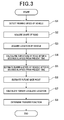
Fig. 3 is a flowchart showing a processing executed by the on-vehicle acoustic apparatus; -
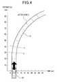
Fig. 4 is an explanatory diagram showing a lattice point L defined on theroad 41 ahead of the own vehicle; -
Fig. 5 is an explanatory diagram showing a spherical surface model of the retina; -
Fig. 6 is an explanatory diagram showing an example of the gaze point; -
Fig. 7 is an explanatory diagram showing an example of the gaze point; -
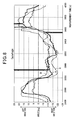
Fig. 8 is a graph showing an experiment result concerning a direction of the observation point of the driver; -
Fig. 9 is a graph showing an experiment result concerning an acceleration factor of a vehicle equipped with the on-vehicle acoustic apparatus; -
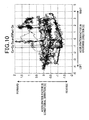
Fig. 10 is a graph showing an experiment result concerning an acceleration factor of a vehicle without the on-vehicle acoustic apparatus; and -
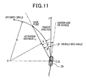
Fig. 11 is an explanatory diagram showing a method of estimating the gaze point by using look-ahead gaze point model. - With reference to the drawings, embodiments according to the present disclosure are described as follows.
- With reference to
Figs. 1 and2 , hereinafter is described a configuration of the on-vehicle acoustic apparatus 1 (acoustic apparatus). The on-vehicleacoustic apparatus 1 is an on-vehicle system which is mounted on a vehicle (hereinafter referred to own vehicle). The on-vehicleacoustic apparatus 1 includes anenvironmental recognition system 3, an on-vehicle sensor system 5, a future vehicle behavior estimation system 7 (first estimator), a future gaze point estimation system (acquiring means, second estimator) 9, a three-dimensional sound acoustic system (localization means, audio processor) 11, an audio system (localization means, generation means, audio system) 13. - The environmental recognition system 3 (recognition device) includes well-known
navigation system 15, acamera 17 capable of taking images around the own vehicle. Thenavigation system 15 includes map information (including road information) and GPS (Global Positioning System) function so that the location of the own vehicle on the road can be identified. - The on-vehicle sensor system 5 (sensor device) includes a
wheel speed sensor 19, agyro sensor 21. Therefore, the on-vehicle sensor system 5 can detect running speed V of the own vehicle by using thewheel speed sensor 19 and yaw rate y of the own vehicle by using thegyro sensor 21. - The future vehicle behavior estimation system 7 (first estimator), the future gaze point estimation system 9 (second estimator) and the three-dimensional sound acoustic system 11 (audio processor) are constituted by well-known computers (CPU: central processing unit and its peripheral circuits) and execute a processing (i.e., computer program) which is described later. The future vehicle
behavior estimation system 7, the future gazepoint estimation system 9 and the three-dimensional soundacoustic system 11 includes amemory unit 7a, amemory unit 9a and amemory unit 11a respectively and the computer program that executes the processing described later is stored in these memory units. - As shown in
Fig. 2 . theaudio system 13 includes a plurality ofsound source audio system 13 operates in response to sound data, SD, transmitted from the three-dimensional soundacoustic system 11. - The sound
source selection unit 29 selects one sound source used for sound image generation from among the plurality ofsound sources filter 31 performs filtering on the sound source data of the sound source selected by the soundsource selection unit 29, based on a transfer function. The sound source data after the filtering is outputted to the R-speaker 35. The L-filter 33 performs filtering on the sound source data of the sound source selected by the soundsource selection unit 29, based on a transfer function. The sound source data after the filtering is outputted to the L-speaker 37. It is noted that the sound image is a virtual sound source where the human ears sense the sound with a distance and a direction thereof. The location of the sound image can be controlled by using a well-known method (sound image localization which is described later). Specifically, as shown inFig. 1 , the driver P recognizes the sound image based on the sound transmitted from the R-speaker 35 and the L-speaker 37. - The transfer functions at the L-
filter 33 and the R-speaker 35 can be determined with a method which is described later. These transfer functions are used for a well-known technique, sound image localization. Specifically, the sound image localization is a Head-Related Transfer Function (i.e., HRTF) which represents transfer characteristics of sound transferred from the virtual source (according to the present disclosure, gaze point (described later) is employed) to the tympanum of the listener. The R-filter 31 and the L-filter 33 performs an inverse filtering process based on the transaural method to drive the speaker output. - R-
speaker 35 and L-speaker 37 are disposed at the right side of the driver's seat and the left side of the driver's seat in the passenger compartment respectively. The sound image generated by the R-speaker 35 and the L-speaker 37 is localized to a gaze point by using a transfer function corresponding to the gaze point which is described later. In other words, the driver feels the sound image as if the sound is coming from the direction towards the gaze point with a distance therebetween. - With reference to
Figs. 3 to 7 , processing executed by the on-vehicleacoustic apparatus 1 is described as follows. The on-vehicleacoustic apparatus 1 repeatedly executes the processing with a predetermined period. At thestep 1 as shown inFig. 3 , the on-vehicle sensor system 5 detects the running speed V of the own vehicle by using thewheel speed sensor 19. - At
step 2, theenvironmental recognition system 3 acquires the shape of the road in front of the own vehicle by using thenavigation system 15. Atstep 3, theenvironmental recognition system 3 acquires the location of the own vehicle (location of the own vehicle on the road of which shape is acquired at the step 2) by using thenavigation system 15. - At
step 4, the future vehiclebehavior estimation system 7 calculates a curvature of the road at which the own vehicle is running after N seconds (N is real number larger than 0) elapsed from the present time. In other words, the future vehiclebehavior estimation system 7 calculates by using the location of the own vehicle acquired at thestep 3, the location of the own vehicle on the road of which shape is acquired at thestep 2 at a time after the own vehicle runs for N seconds at the running speed V acquired at thestep 1 and calculates the curvature of the road at the calculated location. The curvature of the road is one of examples of the running environment of the vehicle. - At
step 5, the future vehiclebehavior estimation system 7 estimates the running state of the own vehicle (running speed V, yaw rate y) after N seconds elapse from the present time by using the curvature calculated at thestep 4. It is assumed that the running speed of the vehicle after N seconds elapsed from the present time is the same as the running speed at the present time. The yaw rate y at a time N seconds after the present time is produced by using the calculated curvature and the running speed V as described above. Atstep 6, the future gazepoint estimation system 9 estimates the gaze point after N seconds elapsed from the present time (i.e., future gaze point). It is noted that the gaze point can be calculated by a method disclosed by Japanese Patent No.4735676 - First, as shown in
Fig. 4 , the future gazepoint estimation system 9 virtually sets a plurality of lattice points L after N seconds from the present time, with constant intervals on theroad 41 ahead of theown vehicle 39 and acquires locations of the respective lattice points L and distances with respect to the location of theown vehicle 39 at a time after N seconds from the present time. The locations of the respective lattice points L and the distances can be acquired by using the map information included in thenavigation system 15. - Next, the process estimates a change rate A of a head-rotation-angle of the driver at a time when the N seconds laps from the present time. The head-rotation-angle is defined as an angle of the motion of the driver's head in the horizontal direction. The change rate A of the head-rotation-angle can be estimated from the curvature of the road calculated at the above-described
step 4. Subsequently, with respect to theown vehicle 39 at a time N seconds from the present time, momentum of the respective lattice points L (hereinafter referred to visual momentum) is calculated when the respective lattice points L are mapped onto the spherical surface model of the retina.Fig. 5 is a diagram showing a spherical surface model of the retina. The spherical surface model of the retina is that the retina of the driver is modeled as a spherical surface and the position of an object on the spherical surface model of the retina corresponds to a position of the object in the coordinate of the retina (retina coordinate). - Assuming the azimuth of the object is θ and the angle of elevation is ϕ, location of any one of lattice points L on the spherical surface model of the retina with respect to the own vehicle at a time N seconds from the present time is represented as (θ, ϕ). Then, the process calculates an absolute value of a change rate of an eccentric angle w (eccentric angle change rate) to be the visual momentum. The eccentric angle change rate is represented as the following equation where running speed of vehicle is V, distance to the lattice point L is R, yaw rate is y and the change rate of the head-rotation-angle is A. The running speed of the vehicle V used in the equation and the yaw rate y are values estimated at the above-described
step 5. Also, the change rate of the head-rotation-angle A used in the following equation is a change rate of the head-rotation-angle at a time N seconds later than the present time.
- The gaze point at a time N seconds from the present time is defined such that the change rate of an eccentric angle regarding the respective lattice points L are calculated and the lattice point L of which absolute value of the change rate of the eccentric angle becomes minimum is set as the gaze point at a time N seconds from the present time. For example, the gaze point is illustrated in
Figs. 6 to 7 . Since the change rate of the eccentric angle is calculated by using the spherical surface model of the retina, the change rate of the eccentric angle indicates visual momentum of the lattice point L on the road. Also, it is apparent psychologically and empirically that the driver tends to look at the minimum point of the visual momentum while driving the own vehicle. Further, it is estimated that the driver looks somewhere on the road when driving the own vehicle. Therefore, the lattice point L of which the absolute value of the change rate of the eccentric angle (visual momentum) becomes a minimum is set as the gaze point. - The above-described gaze point is estimated based on parameters at a time N seconds from the present time including the location of the
own vehicle 39, the running state of the own vehicle (running speed V, yaw rate y) and the running environment of the vehicle (the curvature of the road). In other words, these parameters including the location, the running state and the running environment are reflected to the gaze point. Atstep 7, the future gazepoint estimation system 9 converts, the location of the gaze point at a time N seconds from the present time acquired at thestep 6, to be a location with respect to the three dimensional orthogonal coordinate system. The converted location with respect to the three dimensional orthogonal coordinate system is defined as a target localized location. The gaze point and the target localization location are different in the coordinate system, however, the location themselves are identical. - At
step 8, the three-dimensional soundacoustic system 11 determines a transfer function used for the R-filter 31 and a transfer function used for L-filter 33 in response to the target localized location acquired at thestep 7. Theaudio system 13 stores in advance a plurality of transfer functions each corresponding to respective target localized locations and selects a transfer function based on the target localized location acquired at thestep 7. - The sound image generated by the
audio system 13 by using the transfer function determined by thestep 8 localizes to the target localized location acquired at thestep 7. In other words, the driver feels as if the sound generated by theaudio system 13 came from the direction towards the target localized location with a distance away therefrom. The sound image can be generated continuously while the vehicle is driven by the driver or, can be generated when a predetermined condition is met. It is noted that theaudio system 13 preferably generates the sound image before N seconds elapses from the present time. - The advantages of the on-vehicle
acoustic apparatus 1 are described as follows. - (1) The on-vehicle
acoustic apparatus 1 controls the sound image in the passenger compartment to be localized at the gaze point (In other words, the driver feel as if the sound came from the direction towards the gaze point with a distance away therefrom). Generally, since persons including the driver pay attention instinctively to the direction where the sound is coming from, the driver pays attention to the direction towards the gaze point when the on-vehicleacoustic apparatus 1 is employed. As a result, observation point of the driver can be led to an appropriate direction when driving the own vehicle. - (2) The on-vehicle
acoustic apparatus 1 controls the sound image to be localized to a future gaze point (gaze point after N seconds elapses from the present time). Hence, the observation point of the driver can be led in advance to a direction to be recognized in the future. Assuming the on-vehicleacoustic apparatus 1 estimates the gaze point so that a time lag occurs in the processing for sound image to be localized to the gaze point, the time lag can be cancelled. - (3) In the on-vehicle
acoustic apparatus 1, the user can select sound source among a plurality of sound sources whereby user's observation point can be led to an appropriate direction effectively. - The followings are a confirmation test for advantages of the on-vehicle
acoustic apparatus 1. - The same driver drives the own vehicle in the same test course with/without the on-vehicle
acoustic apparatus 1 and the direction of the observation point of the driver is continuously measured. Moreover, an acceleration factor at longitudinal direction of the own vehicle and an acceleration factor at crosswise direction of the own vehicle are continuously measured. -
Fig. 8 is a graph showing a change in a direction of the observation point of the driver while driving the own vehicle. The vertical axis ofFig. 8 represents a direction (angle) of the observation point of the driver when the exact front direction of the own vehicle is defined as 0 degree and the horizontal axis ofFig. 8 represents the measurement time. The A curve represents a change in a direction of the observation point of the driver when the on-vehicleacoustic apparatus 1 is mounted on the own vehicle. The B curve represents a change in a direction of the observation point of the driver when the on-vehicleacoustic apparatus 1 is not mounted on the own vehicle. The X curve represents a change in a direction of the gaze point. - As a result, an amount of change in the direction of the observation point of the driver when the on-vehicle
acoustic apparatus 1 is mounted on the own vehicle (i.e., A curve) is larger than the amount of change when the on-vehicleacoustic apparatus 1 is not mounted on the own vehicle (i.e., B curve) and represents similar characteristics of the gaze point (i.e., X curve). This means that the observation point of the driver is led to the gaze point when the on-vehicleacoustic apparatus 1 is mounted on the own vehicle. As a result, for example, when the own vehicle is running on a curved road, the observation point of the driver is brought to a point further along the curved section of the curved road. -
Fig. 9 is a graph showing a trend of an acceleration factor at longitudinal direction of the own vehicle (vertical axis) and a trend of an acceleration factor at crosswise direction of the own vehicle (horizontal axis), when the on-vehicleacoustic apparatus 1 is mounted on the own vehicle. Further,Fig. 10 is a graph showing a trend of an acceleration factor at longitudinal direction of the own vehicle and a trend of an acceleration factor at crosswise direction of the own vehicle, when the on-vehicleacoustic apparatus 1 is not mounted on the own vehicle. Comparing the trends as shown inFigs. 9 and10 , the behavior of the acceleration factors as shown inFig. 9 are continuously smoother than in theFig. 10 . Meanwhile, in the behavior as shown inFig. 10 , direction of the acceleration factor or an amount of the acceleration factor changes rapidly. According to the above-described results, the on-vehicleacoustic apparatus 1 can appropriately lead the driving operation of the driver. - The configuration and advantages of the on-vehicle
acoustic apparatus 1 according to the second embodiment is the same as the one of the first embodiment. Hence, configurations identical to that of the first embodiment are labeled with the same reference numbers and explanation thereof is omitted. In the first embodiment, the on-vehicleacoustic apparatus 1 estimates a gaze point in which the location of the own vehicle, the running state of the own vehicle and the running environment of the own vehicle at a time when N seconds elapse from the present time are reflected. In the second embodiment, the on-vehicleacoustic apparatus 1 alternatively estimates a gaze point that reflects parameters at a time when the own vehicle reaches at a location with a predetermined distance away from the present location, including the location of the own vehicle, the running state of the own vehicle and the running environment of the own vehicle. In this case, at thestep 4, the future vehiclebehavior estimation system 7 calculates a curvature of the road at a location with a predetermined distance away from the present location. At thestep 5, the future vehiclebehavior estimation system 7 estimates the running state of the own vehicle (running speed V, yaw rate y) at the curvature estimated at thestep 4. Moreover, at step6, the future gazepoint estimation system 9 virtually sets lattice points with constant intervals on theroad 41 ahead of the own vehicle at a location with predetermined distance away from the present location and estimates the gaze point. According to the on-vehicleacoustic apparatus 1 of the second embodiment, similar effects of the one in the first embodiment can be obtained. - The configuration and advantages of the on-vehicle
acoustic apparatus 1 according to the third embodiment is the same as the one of the first embodiment or the second embodiment. In the third embodiment, estimating method of the gaze point is different from that of the first embodiment and the second embodiment. - According to the third embodiment, the gaze point is estimated by using a look-ahead gaze point model. With reference to
Fig. 11 , the look-ahead gaze point model is described as follows.Fig. 11 shows a situation where theown vehicle 39 exists on the road of which curvature is R, after N seconds elapse from the present time. The specified circuit in theFig. 11 is a circle of which curvature is R corresponding to the road, being exist closely to theown vehicle 39. It is noted that tangent direction of the specified circle and the center axis of the vehicle (center line of the vehicle which is in parallel to the longitudinal direction thereof) make a vehicle skid angle β. An attention distance L2 is defined as a product of a margin time and the running speed of the own vehicle. A point on the circumference of the specified circle being exist with the attention distance L2 away from the center of the vehicle is defined as a gaze point. This gaze point also reflects a location of the vehicle, a running state of the own vehicle (running speed V, yaw rate y) and the running environment of the own vehicle (curvature of the road). - According to the on-vehicle
acoustic apparatus 1 of the third embodiment, similar advantages of the one in the first embodiment or the second embodiment can be obtained. - The configuration and the advantages of the on-vehicle
acoustic apparatus 1 of the fourth embodiment are similar to that of first embodiment. However, unlike the future gaze point described in the first embodiment, according to the fourth embodiment, the gaze point is estimated at the present time and the sound image is localized to the gaze point. - In this case, at the above-described
step 4, the on-vehicleacoustic apparatus 1 calculates the curvature of the road on which the own vehicle exists at the present time. Further, at the above-describedstep 5, the on-vehicleacoustic apparatus 1 estimates the running state (running speed V, yaw rate y) of the own vehicle at the present time. In this case, the yaw rate y can be estimated by using thegyro sensor 21 of the on-vehicle sensor system 5. - Furthermore, at the above-described
step 6, the future gazepoint estimation system 9 virtually sets lattice points with constant intervals on theroad 41 ahead of the own vehicle at the present time and estimates the gaze point. - According to the on-vehicle
acoustic apparatus 1 of the fourth embodiment, observation point of the driver can be led to an appropriate direction when driving the own vehicle as well. The present disclosure is not limited to those embodiments described above, and may include various types of modifications within the technical scope of the present disclosure. - For example, the gaze point can be estimated with other method as far as the gaze point reflects the location of the own vehicle, the running state of the own vehicle and the running environment of the vehicle. Even in this case, the gaze point should preferably be at a location where the driver should pay attention while driving the own vehicle.
- The running environment of the own vehicle used for determining the gaze point is not limited to the curvature of the road. For example, the running environment includes locations of other vehicles, running direction of other vehicles, running speed of other vehicle, a condition of the road (e.g. an obstacle on the road, an icy road, a puddle on the road, road covered with snow, cracks in the road, uneven road features etc.), weather conditions including rain, snow, fog and temperature and brightness outside the own vehicle.
Claims (8)
- An acoustic apparatus (1) mounted on a vehicle driven by a driver comprising:acquiring means (9) for acquiring a gaze point at which the driver gazes while driving the vehicle, the gaze point reflecting parameters including a location of the vehicle, a running state of the vehicle and a running environment of the vehicle;generation means (13) for generating a sound image in the vehicle; andlocalization means (11, 13) for localizing the sound image to be at the gaze point.
- The acoustic apparatus according to claim 1, wherein the acquiring means is adapted to acquire a future gaze point existing at a future time and localize the sound image to be at the future gaze point.
- The acoustic apparatus according to claim 2, wherein the future gaze point reflects the parameters at a time delayed by a predetermined period from a time when the gaze point is acquired.
- The acoustic apparatus according to claim 2, wherein the future gaze point reflects the parameters at a time when the vehicle reaches a location a predetermined distance away from a location where the gaze point was acquired.
- The acoustic apparatus according to any one of claims 1 to 4, wherein the acoustic apparatus further includes selecting means (29) for selecting a sound source used for the sound image from among a plurality of sound sources (23, 25, 27).
- A method for controlling a sound image in a vehicle driven by a driver, comprising steps of:acquiring (9) a gaze point at which the driver gazes while driving the vehicle, the gaze point reflecting parameters including a location of the vehicle, a running state of the vehicle and a running environment of the vehicle;generating (13) the sound image in the vehicle; andlocalizing (11, 13) the sound image to be at the gaze point.
- The method according to claim 6, wherein the acquiring step is adapted to acquire a future gaze point existing at a future time and localize the sound image to be at the future gaze point.
- The method according to claim 7, wherein the future gaze point reflects the parameters at a time delayed by a predetermined period from a time when the gaze point is acquired.
Applications Claiming Priority (1)
| Application Number | Priority Date | Filing Date | Title |
|---|---|---|---|
| JP2012160640A JP5664603B2 (en) | 2012-07-19 | 2012-07-19 | On-vehicle acoustic device and program |
Publications (2)
| Publication Number | Publication Date |
|---|---|
| EP2687407A1 true EP2687407A1 (en) | 2014-01-22 |
| EP2687407B1 EP2687407B1 (en) | 2017-07-05 |
Family
ID=48832751
Family Applications (1)
| Application Number | Title | Priority Date | Filing Date |
|---|---|---|---|
| EP13176317.9A Not-in-force EP2687407B1 (en) | 2012-07-19 | 2013-07-12 | Apparatus and method for localizing sound image for vehicle's driver |
Country Status (4)
| Country | Link |
|---|---|
| US (1) | US9451380B2 (en) |
| EP (1) | EP2687407B1 (en) |
| JP (1) | JP5664603B2 (en) |
| CN (1) | CN103568992B (en) |
Cited By (2)
| Publication number | Priority date | Publication date | Assignee | Title |
|---|---|---|---|---|
| CN109445597A (en) * | 2018-11-06 | 2019-03-08 | 北京七鑫易维信息技术有限公司 | A kind of operation indicating method, apparatus and terminal applied to terminal |
| WO2019175273A1 (en) * | 2018-03-14 | 2019-09-19 | Sony Corporation | Electronic device, method and computer program |
Families Citing this family (13)
| Publication number | Priority date | Publication date | Assignee | Title |
|---|---|---|---|---|
| JP5838962B2 (en) * | 2012-12-27 | 2016-01-06 | 株式会社デンソー | Sound image localization apparatus and program |
| JP5668765B2 (en) | 2013-01-11 | 2015-02-12 | 株式会社デンソー | In-vehicle acoustic device |
| JP6470041B2 (en) * | 2014-12-26 | 2019-02-13 | 株式会社東芝 | Navigation device, navigation method and program |
| CN108885830B (en) * | 2016-03-30 | 2021-03-16 | 三菱电机株式会社 | Notification control device and notification control method |
| JP6465058B2 (en) * | 2016-03-31 | 2019-02-06 | マツダ株式会社 | Sound effect generator for vehicles |
| US10979843B2 (en) | 2016-04-08 | 2021-04-13 | Qualcomm Incorporated | Spatialized audio output based on predicted position data |
| KR101905993B1 (en) * | 2016-10-31 | 2018-10-10 | 현대자동차주식회사 | Interior parts for vehicle and method for manufacturing the same |
| JP7015860B2 (en) | 2020-03-31 | 2022-02-03 | 本田技研工業株式会社 | vehicle |
| JP7013515B2 (en) | 2020-03-31 | 2022-01-31 | 本田技研工業株式会社 | vehicle |
| JP7013513B2 (en) | 2020-03-31 | 2022-01-31 | 本田技研工業株式会社 | vehicle |
| DE102020110974B3 (en) * | 2020-04-22 | 2021-05-20 | Dr. Ing. H.C. F. Porsche Aktiengesellschaft | Method for simulating a noise in a motor vehicle and motor vehicle |
| CN112101461B (en) * | 2020-09-16 | 2022-02-25 | 北京邮电大学 | An Audible Method of UAV Reconnaissance Visual Information Based on HRTF-PSO-FCM |
| KR20230090051A (en) | 2021-12-14 | 2023-06-21 | 현대자동차주식회사 | Apparatus and method for controlling vehicle sound |
Citations (8)
| Publication number | Priority date | Publication date | Assignee | Title |
|---|---|---|---|---|
| JPH097100A (en) * | 1995-06-19 | 1997-01-10 | Honda Motor Co Ltd | Driver gaze point prediction device and vehicle driving support system using the device |
| DE19801205A1 (en) * | 1997-01-24 | 1998-07-30 | Volkswagen Ag | Acoustic obstacle warning arrangement for motor vehicle |
| EP1033557A2 (en) * | 1999-03-04 | 2000-09-06 | Sony Corporation | Navigation apparatus |
| US20050270146A1 (en) * | 2004-06-07 | 2005-12-08 | Denso Corporation | Information processing system |
| JP3945488B2 (en) | 2004-02-24 | 2007-07-18 | 日産自動車株式会社 | Lane departure prevention device |
| JP2008084219A (en) * | 2006-09-28 | 2008-04-10 | Aisin Seiki Co Ltd | Forward curve alarm device |
| JP2008129734A (en) * | 2006-11-17 | 2008-06-05 | Calsonic Kansei Corp | Solid sound image warning device |
| EP2154593A2 (en) * | 2008-08-06 | 2010-02-17 | Denso Corporation | Apparatus for travel support |
Family Cites Families (18)
| Publication number | Priority date | Publication date | Assignee | Title |
|---|---|---|---|---|
| JP2689792B2 (en) | 1991-10-30 | 1997-12-10 | 日産自動車株式会社 | Three-dimensional sound field alarm device |
| JPH07159190A (en) * | 1993-12-09 | 1995-06-23 | Zanabui Informatics:Kk | Sound device totallizing system on vehicle |
| WO2002096718A1 (en) * | 2001-05-28 | 2002-12-05 | Mitsubishi Denki Kabushiki Kaisha | Apparatus for supporting drive |
| JP3846229B2 (en) | 2001-06-14 | 2006-11-15 | 日産自動車株式会社 | Lane departure warning device |
| JP4205442B2 (en) | 2003-01-16 | 2009-01-07 | 本田技研工業株式会社 | Steering device |
| US6859144B2 (en) * | 2003-02-05 | 2005-02-22 | Delphi Technologies, Inc. | Vehicle situation alert system with eye gaze controlled alert signal generation |
| JP4547985B2 (en) * | 2004-05-18 | 2010-09-22 | 日産自動車株式会社 | Driver perception control device |
| JP2006019908A (en) * | 2004-06-30 | 2006-01-19 | Denso Corp | Notification sound output device for vehicle and program |
| JP4321450B2 (en) * | 2004-07-26 | 2009-08-26 | 株式会社デンソー | Visual recognition support device |
| EP1961622B1 (en) * | 2005-12-12 | 2018-06-13 | Panasonic Intellectual Property Corporation of America | Safety-travel assistance device |
| US8054201B2 (en) | 2008-03-19 | 2011-11-08 | Mazda Motor Corporation | Surroundings monitoring device for vehicle |
| JP2009231938A (en) * | 2008-03-19 | 2009-10-08 | Mazda Motor Corp | Surrounding monitoring device for vehicle |
| JP4557054B2 (en) | 2008-06-20 | 2010-10-06 | 株式会社デンソー | In-vehicle stereophonic device |
| US8212659B2 (en) * | 2008-09-05 | 2012-07-03 | Mazda Motor Corporation | Driving assist device for vehicle |
| JP5217950B2 (en) * | 2008-11-20 | 2013-06-19 | トヨタ自動車株式会社 | Driving assistance device |
| US8564502B2 (en) * | 2009-04-02 | 2013-10-22 | GM Global Technology Operations LLC | Distortion and perspective correction of vector projection display |
| US8384532B2 (en) * | 2009-04-02 | 2013-02-26 | GM Global Technology Operations LLC | Lane of travel on windshield head-up display |
| JP5327025B2 (en) * | 2009-12-03 | 2013-10-30 | アイシン・エィ・ダブリュ株式会社 | Vehicle travel guidance device, vehicle travel guidance method, and computer program |
-
2012
- 2012-07-19 JP JP2012160640A patent/JP5664603B2/en not_active Expired - Fee Related
-
2013
- 2013-07-12 EP EP13176317.9A patent/EP2687407B1/en not_active Not-in-force
- 2013-07-18 US US13/944,925 patent/US9451380B2/en not_active Expired - Fee Related
- 2013-07-19 CN CN201310306224.0A patent/CN103568992B/en not_active Expired - Fee Related
Patent Citations (9)
| Publication number | Priority date | Publication date | Assignee | Title |
|---|---|---|---|---|
| JPH097100A (en) * | 1995-06-19 | 1997-01-10 | Honda Motor Co Ltd | Driver gaze point prediction device and vehicle driving support system using the device |
| DE19801205A1 (en) * | 1997-01-24 | 1998-07-30 | Volkswagen Ag | Acoustic obstacle warning arrangement for motor vehicle |
| EP1033557A2 (en) * | 1999-03-04 | 2000-09-06 | Sony Corporation | Navigation apparatus |
| JP3945488B2 (en) | 2004-02-24 | 2007-07-18 | 日産自動車株式会社 | Lane departure prevention device |
| US20050270146A1 (en) * | 2004-06-07 | 2005-12-08 | Denso Corporation | Information processing system |
| JP2008084219A (en) * | 2006-09-28 | 2008-04-10 | Aisin Seiki Co Ltd | Forward curve alarm device |
| JP2008129734A (en) * | 2006-11-17 | 2008-06-05 | Calsonic Kansei Corp | Solid sound image warning device |
| EP2154593A2 (en) * | 2008-08-06 | 2010-02-17 | Denso Corporation | Apparatus for travel support |
| JP4735676B2 (en) | 2008-08-06 | 2011-07-27 | 株式会社デンソー | Driving support device |
Cited By (4)
| Publication number | Priority date | Publication date | Assignee | Title |
|---|---|---|---|---|
| WO2019175273A1 (en) * | 2018-03-14 | 2019-09-19 | Sony Corporation | Electronic device, method and computer program |
| US11457328B2 (en) | 2018-03-14 | 2022-09-27 | Sony Corporation | Electronic device, method and computer program |
| US12075231B2 (en) | 2018-03-14 | 2024-08-27 | Sony Group Corporation | Electronic device, method and computer program |
| CN109445597A (en) * | 2018-11-06 | 2019-03-08 | 北京七鑫易维信息技术有限公司 | A kind of operation indicating method, apparatus and terminal applied to terminal |
Also Published As
| Publication number | Publication date |
|---|---|
| JP2014021770A (en) | 2014-02-03 |
| JP5664603B2 (en) | 2015-02-04 |
| CN103568992B (en) | 2017-03-01 |
| US20140023211A1 (en) | 2014-01-23 |
| EP2687407B1 (en) | 2017-07-05 |
| US9451380B2 (en) | 2016-09-20 |
| CN103568992A (en) | 2014-02-12 |
Similar Documents
| Publication | Publication Date | Title |
|---|---|---|
| US9451380B2 (en) | Apparatus and method for localizing sound image for vehicle's driver | |
| US11794788B2 (en) | Automatic driving system | |
| US9527441B2 (en) | Vehicle control apparatus | |
| US8965037B2 (en) | Visual input of vehicle operator | |
| JP6638701B2 (en) | Driving awareness estimation device | |
| US9308917B2 (en) | Driver assistance apparatus capable of performing distance detection and vehicle including the same | |
| JP2018185673A (en) | Driving support device and driving support program | |
| US20220253065A1 (en) | Information processing apparatus, information processing method, and information processing program | |
| WO2019131116A1 (en) | Information processing device, moving device and method, and program | |
| JP7156924B2 (en) | Lane boundary setting device, lane boundary setting method | |
| US11008012B2 (en) | Driving consciousness estimation device | |
| KR102644324B1 (en) | Autonomous driving apparatus and method | |
| WO2022158272A1 (en) | Processing method, processing system, processing program, and processing device | |
| JP7263962B2 (en) | VEHICLE DISPLAY CONTROL DEVICE AND VEHICLE DISPLAY CONTROL METHOD | |
| JP2023175206A (en) | Driving support devices, driving support methods, and programs | |
| US20260061999A1 (en) | Driving assistance system, driving assistance device, driving assistance method, and program | |
| JP7358958B2 (en) | Driving awareness estimation device | |
| WO2024252912A1 (en) | Information processing device, information processing method, and information processing system | |
| JP2025037722A (en) | Driving assistance system, driving assistance program, and driving assistance method | |
| JP2025125309A (en) | Driver state estimation device |
Legal Events
| Date | Code | Title | Description |
|---|---|---|---|
| PUAI | Public reference made under article 153(3) epc to a published international application that has entered the european phase |
Free format text: ORIGINAL CODE: 0009012 |
|
| AK | Designated contracting states |
Kind code of ref document: A1 Designated state(s): AL AT BE BG CH CY CZ DE DK EE ES FI FR GB GR HR HU IE IS IT LI LT LU LV MC MK MT NL NO PL PT RO RS SE SI SK SM TR |
|
| AX | Request for extension of the european patent |
Extension state: BA ME |
|
| 17P | Request for examination filed |
Effective date: 20140714 |
|
| RBV | Designated contracting states (corrected) |
Designated state(s): AL AT BE BG CH CY CZ DE DK EE ES FI FR GB GR HR HU IE IS IT LI LT LU LV MC MK MT NL NO PL PT RO RS SE SI SK SM TR |
|
| RIC1 | Information provided on ipc code assigned before grant |
Ipc: G08G 1/0962 20060101ALI20160613BHEP Ipc: B60Q 9/00 20060101AFI20160613BHEP Ipc: G08G 1/16 20060101ALI20160613BHEP |
|
| 17Q | First examination report despatched |
Effective date: 20160627 |
|
| GRAP | Despatch of communication of intention to grant a patent |
Free format text: ORIGINAL CODE: EPIDOSNIGR1 |
|
| INTG | Intention to grant announced |
Effective date: 20161208 |
|
| GRAS | Grant fee paid |
Free format text: ORIGINAL CODE: EPIDOSNIGR3 |
|
| RAP1 | Party data changed (applicant data changed or rights of an application transferred) |
Owner name: DENSO CORPORATION |
|
| RIN1 | Information on inventor provided before grant (corrected) |
Inventor name: TOTSUKA, SEIJI Inventor name: KUDOU, KENJI Inventor name: INOU, HIROSHI |
|
| GRAA | (expected) grant |
Free format text: ORIGINAL CODE: 0009210 |
|
| AK | Designated contracting states |
Kind code of ref document: B1 Designated state(s): AL AT BE BG CH CY CZ DE DK EE ES FI FR GB GR HR HU IE IS IT LI LT LU LV MC MK MT NL NO PL PT RO RS SE SI SK SM TR |
|
| REG | Reference to a national code |
Ref country code: GB Ref legal event code: FG4D |
|
| REG | Reference to a national code |
Ref country code: CH Ref legal event code: EP |
|
| REG | Reference to a national code |
Ref country code: AT Ref legal event code: REF Ref document number: 906350 Country of ref document: AT Kind code of ref document: T Effective date: 20170715 |
|
| REG | Reference to a national code |
Ref country code: FR Ref legal event code: PLFP Year of fee payment: 5 |
|
| REG | Reference to a national code |
Ref country code: IE Ref legal event code: FG4D |
|
| REG | Reference to a national code |
Ref country code: DE Ref legal event code: R096 Ref document number: 602013023057 Country of ref document: DE |
|
| REG | Reference to a national code |
Ref country code: DE Ref legal event code: R084 Ref document number: 602013023057 Country of ref document: DE |
|
| REG | Reference to a national code |
Ref country code: NL Ref legal event code: MP Effective date: 20170705 |
|
| REG | Reference to a national code |
Ref country code: AT Ref legal event code: MK05 Ref document number: 906350 Country of ref document: AT Kind code of ref document: T Effective date: 20170705 |
|
| REG | Reference to a national code |
Ref country code: LT Ref legal event code: MG4D |
|
| PG25 | Lapsed in a contracting state [announced via postgrant information from national office to epo] |
Ref country code: AT Free format text: LAPSE BECAUSE OF FAILURE TO SUBMIT A TRANSLATION OF THE DESCRIPTION OR TO PAY THE FEE WITHIN THE PRESCRIBED TIME-LIMIT Effective date: 20170705 Ref country code: NL Free format text: LAPSE BECAUSE OF FAILURE TO SUBMIT A TRANSLATION OF THE DESCRIPTION OR TO PAY THE FEE WITHIN THE PRESCRIBED TIME-LIMIT Effective date: 20170705 Ref country code: FI Free format text: LAPSE BECAUSE OF FAILURE TO SUBMIT A TRANSLATION OF THE DESCRIPTION OR TO PAY THE FEE WITHIN THE PRESCRIBED TIME-LIMIT Effective date: 20170705 Ref country code: HR Free format text: LAPSE BECAUSE OF FAILURE TO SUBMIT A TRANSLATION OF THE DESCRIPTION OR TO PAY THE FEE WITHIN THE PRESCRIBED TIME-LIMIT Effective date: 20170705 Ref country code: SE Free format text: LAPSE BECAUSE OF FAILURE TO SUBMIT A TRANSLATION OF THE DESCRIPTION OR TO PAY THE FEE WITHIN THE PRESCRIBED TIME-LIMIT Effective date: 20170705 Ref country code: LT Free format text: LAPSE BECAUSE OF FAILURE TO SUBMIT A TRANSLATION OF THE DESCRIPTION OR TO PAY THE FEE WITHIN THE PRESCRIBED TIME-LIMIT Effective date: 20170705 Ref country code: NO Free format text: LAPSE BECAUSE OF FAILURE TO SUBMIT A TRANSLATION OF THE DESCRIPTION OR TO PAY THE FEE WITHIN THE PRESCRIBED TIME-LIMIT Effective date: 20171005 |
|
| PG25 | Lapsed in a contracting state [announced via postgrant information from national office to epo] |
Ref country code: BG Free format text: LAPSE BECAUSE OF FAILURE TO SUBMIT A TRANSLATION OF THE DESCRIPTION OR TO PAY THE FEE WITHIN THE PRESCRIBED TIME-LIMIT Effective date: 20171005 Ref country code: ES Free format text: LAPSE BECAUSE OF FAILURE TO SUBMIT A TRANSLATION OF THE DESCRIPTION OR TO PAY THE FEE WITHIN THE PRESCRIBED TIME-LIMIT Effective date: 20170705 Ref country code: GR Free format text: LAPSE BECAUSE OF FAILURE TO SUBMIT A TRANSLATION OF THE DESCRIPTION OR TO PAY THE FEE WITHIN THE PRESCRIBED TIME-LIMIT Effective date: 20171006 Ref country code: IS Free format text: LAPSE BECAUSE OF FAILURE TO SUBMIT A TRANSLATION OF THE DESCRIPTION OR TO PAY THE FEE WITHIN THE PRESCRIBED TIME-LIMIT Effective date: 20171105 Ref country code: RS Free format text: LAPSE BECAUSE OF FAILURE TO SUBMIT A TRANSLATION OF THE DESCRIPTION OR TO PAY THE FEE WITHIN THE PRESCRIBED TIME-LIMIT Effective date: 20170705 Ref country code: PL Free format text: LAPSE BECAUSE OF FAILURE TO SUBMIT A TRANSLATION OF THE DESCRIPTION OR TO PAY THE FEE WITHIN THE PRESCRIBED TIME-LIMIT Effective date: 20170705 Ref country code: LV Free format text: LAPSE BECAUSE OF FAILURE TO SUBMIT A TRANSLATION OF THE DESCRIPTION OR TO PAY THE FEE WITHIN THE PRESCRIBED TIME-LIMIT Effective date: 20170705 |
|
| REG | Reference to a national code |
Ref country code: CH Ref legal event code: PL |
|
| REG | Reference to a national code |
Ref country code: DE Ref legal event code: R097 Ref document number: 602013023057 Country of ref document: DE |
|
| REG | Reference to a national code |
Ref country code: IE Ref legal event code: MM4A |
|
| PG25 | Lapsed in a contracting state [announced via postgrant information from national office to epo] |
Ref country code: DK Free format text: LAPSE BECAUSE OF FAILURE TO SUBMIT A TRANSLATION OF THE DESCRIPTION OR TO PAY THE FEE WITHIN THE PRESCRIBED TIME-LIMIT Effective date: 20170705 Ref country code: RO Free format text: LAPSE BECAUSE OF FAILURE TO SUBMIT A TRANSLATION OF THE DESCRIPTION OR TO PAY THE FEE WITHIN THE PRESCRIBED TIME-LIMIT Effective date: 20170705 Ref country code: CH Free format text: LAPSE BECAUSE OF NON-PAYMENT OF DUE FEES Effective date: 20170731 Ref country code: CZ Free format text: LAPSE BECAUSE OF FAILURE TO SUBMIT A TRANSLATION OF THE DESCRIPTION OR TO PAY THE FEE WITHIN THE PRESCRIBED TIME-LIMIT Effective date: 20170705 Ref country code: LI Free format text: LAPSE BECAUSE OF NON-PAYMENT OF DUE FEES Effective date: 20170731 Ref country code: MC Free format text: LAPSE BECAUSE OF FAILURE TO SUBMIT A TRANSLATION OF THE DESCRIPTION OR TO PAY THE FEE WITHIN THE PRESCRIBED TIME-LIMIT Effective date: 20170705 Ref country code: IE Free format text: LAPSE BECAUSE OF NON-PAYMENT OF DUE FEES Effective date: 20170712 |
|
| PLBE | No opposition filed within time limit |
Free format text: ORIGINAL CODE: 0009261 |
|
| STAA | Information on the status of an ep patent application or granted ep patent |
Free format text: STATUS: NO OPPOSITION FILED WITHIN TIME LIMIT |
|
| PG25 | Lapsed in a contracting state [announced via postgrant information from national office to epo] |
Ref country code: SM Free format text: LAPSE BECAUSE OF FAILURE TO SUBMIT A TRANSLATION OF THE DESCRIPTION OR TO PAY THE FEE WITHIN THE PRESCRIBED TIME-LIMIT Effective date: 20170705 Ref country code: SK Free format text: LAPSE BECAUSE OF FAILURE TO SUBMIT A TRANSLATION OF THE DESCRIPTION OR TO PAY THE FEE WITHIN THE PRESCRIBED TIME-LIMIT Effective date: 20170705 Ref country code: EE Free format text: LAPSE BECAUSE OF FAILURE TO SUBMIT A TRANSLATION OF THE DESCRIPTION OR TO PAY THE FEE WITHIN THE PRESCRIBED TIME-LIMIT Effective date: 20170705 Ref country code: IT Free format text: LAPSE BECAUSE OF FAILURE TO SUBMIT A TRANSLATION OF THE DESCRIPTION OR TO PAY THE FEE WITHIN THE PRESCRIBED TIME-LIMIT Effective date: 20170705 |
|
| 26N | No opposition filed |
Effective date: 20180406 |
|
| REG | Reference to a national code |
Ref country code: BE Ref legal event code: MM Effective date: 20170731 |
|
| GBPC | Gb: european patent ceased through non-payment of renewal fee |
Effective date: 20171005 |
|
| PG25 | Lapsed in a contracting state [announced via postgrant information from national office to epo] |
Ref country code: LU Free format text: LAPSE BECAUSE OF NON-PAYMENT OF DUE FEES Effective date: 20170712 |
|
| REG | Reference to a national code |
Ref country code: FR Ref legal event code: PLFP Year of fee payment: 6 |
|
| PG25 | Lapsed in a contracting state [announced via postgrant information from national office to epo] |
Ref country code: GB Free format text: LAPSE BECAUSE OF NON-PAYMENT OF DUE FEES Effective date: 20171005 |
|
| PG25 | Lapsed in a contracting state [announced via postgrant information from national office to epo] |
Ref country code: BE Free format text: LAPSE BECAUSE OF NON-PAYMENT OF DUE FEES Effective date: 20170731 Ref country code: SI Free format text: LAPSE BECAUSE OF FAILURE TO SUBMIT A TRANSLATION OF THE DESCRIPTION OR TO PAY THE FEE WITHIN THE PRESCRIBED TIME-LIMIT Effective date: 20170705 |
|
| PG25 | Lapsed in a contracting state [announced via postgrant information from national office to epo] |
Ref country code: MT Free format text: LAPSE BECAUSE OF NON-PAYMENT OF DUE FEES Effective date: 20170712 |
|
| PG25 | Lapsed in a contracting state [announced via postgrant information from national office to epo] |
Ref country code: HU Free format text: LAPSE BECAUSE OF FAILURE TO SUBMIT A TRANSLATION OF THE DESCRIPTION OR TO PAY THE FEE WITHIN THE PRESCRIBED TIME-LIMIT; INVALID AB INITIO Effective date: 20130712 |
|
| PG25 | Lapsed in a contracting state [announced via postgrant information from national office to epo] |
Ref country code: CY Free format text: LAPSE BECAUSE OF NON-PAYMENT OF DUE FEES Effective date: 20170705 |
|
| PG25 | Lapsed in a contracting state [announced via postgrant information from national office to epo] |
Ref country code: MK Free format text: LAPSE BECAUSE OF FAILURE TO SUBMIT A TRANSLATION OF THE DESCRIPTION OR TO PAY THE FEE WITHIN THE PRESCRIBED TIME-LIMIT Effective date: 20170705 |
|
| PG25 | Lapsed in a contracting state [announced via postgrant information from national office to epo] |
Ref country code: TR Free format text: LAPSE BECAUSE OF FAILURE TO SUBMIT A TRANSLATION OF THE DESCRIPTION OR TO PAY THE FEE WITHIN THE PRESCRIBED TIME-LIMIT Effective date: 20170705 |
|
| PG25 | Lapsed in a contracting state [announced via postgrant information from national office to epo] |
Ref country code: PT Free format text: LAPSE BECAUSE OF FAILURE TO SUBMIT A TRANSLATION OF THE DESCRIPTION OR TO PAY THE FEE WITHIN THE PRESCRIBED TIME-LIMIT Effective date: 20170705 |
|
| PG25 | Lapsed in a contracting state [announced via postgrant information from national office to epo] |
Ref country code: AL Free format text: LAPSE BECAUSE OF FAILURE TO SUBMIT A TRANSLATION OF THE DESCRIPTION OR TO PAY THE FEE WITHIN THE PRESCRIBED TIME-LIMIT Effective date: 20170705 |
|
| PGFP | Annual fee paid to national office [announced via postgrant information from national office to epo] |
Ref country code: DE Payment date: 20200721 Year of fee payment: 8 Ref country code: FR Payment date: 20200723 Year of fee payment: 8 |
|
| REG | Reference to a national code |
Ref country code: DE Ref legal event code: R119 Ref document number: 602013023057 Country of ref document: DE |
|
| PG25 | Lapsed in a contracting state [announced via postgrant information from national office to epo] |
Ref country code: DE Free format text: LAPSE BECAUSE OF NON-PAYMENT OF DUE FEES Effective date: 20220201 |
|
| PG25 | Lapsed in a contracting state [announced via postgrant information from national office to epo] |
Ref country code: FR Free format text: LAPSE BECAUSE OF NON-PAYMENT OF DUE FEES Effective date: 20210731 |