EP2687357A1 - Method and system for producing fiber composite components - Google Patents
Method and system for producing fiber composite components Download PDFInfo
- Publication number
- EP2687357A1 EP2687357A1 EP12176588.7A EP12176588A EP2687357A1 EP 2687357 A1 EP2687357 A1 EP 2687357A1 EP 12176588 A EP12176588 A EP 12176588A EP 2687357 A1 EP2687357 A1 EP 2687357A1
- Authority
- EP
- European Patent Office
- Prior art keywords
- cavities
- openings
- molding tool
- matrix material
- semi
- Prior art date
- Legal status (The legal status is an assumption and is not a legal conclusion. Google has not performed a legal analysis and makes no representation as to the accuracy of the status listed.)
- Granted
Links
Images



Classifications
-
- B—PERFORMING OPERATIONS; TRANSPORTING
- B29—WORKING OF PLASTICS; WORKING OF SUBSTANCES IN A PLASTIC STATE IN GENERAL
- B29C—SHAPING OR JOINING OF PLASTICS; SHAPING OF MATERIAL IN A PLASTIC STATE, NOT OTHERWISE PROVIDED FOR; AFTER-TREATMENT OF THE SHAPED PRODUCTS, e.g. REPAIRING
- B29C70/00—Shaping composites, i.e. plastics material comprising reinforcements, fillers or preformed parts, e.g. inserts
- B29C70/04—Shaping composites, i.e. plastics material comprising reinforcements, fillers or preformed parts, e.g. inserts comprising reinforcements only, e.g. self-reinforcing plastics
- B29C70/28—Shaping operations therefor
- B29C70/54—Component parts, details or accessories; Auxiliary operations, e.g. feeding or storage of prepregs or SMC after impregnation or during ageing
- B29C70/546—Measures for feeding or distributing the matrix material in the reinforcing structure
- B29C70/548—Measures for feeding or distributing the matrix material in the reinforcing structure using distribution constructions, e.g. channels incorporated in or associated with the mould
-
- B—PERFORMING OPERATIONS; TRANSPORTING
- B29—WORKING OF PLASTICS; WORKING OF SUBSTANCES IN A PLASTIC STATE IN GENERAL
- B29C—SHAPING OR JOINING OF PLASTICS; SHAPING OF MATERIAL IN A PLASTIC STATE, NOT OTHERWISE PROVIDED FOR; AFTER-TREATMENT OF THE SHAPED PRODUCTS, e.g. REPAIRING
- B29C70/00—Shaping composites, i.e. plastics material comprising reinforcements, fillers or preformed parts, e.g. inserts
- B29C70/04—Shaping composites, i.e. plastics material comprising reinforcements, fillers or preformed parts, e.g. inserts comprising reinforcements only, e.g. self-reinforcing plastics
- B29C70/28—Shaping operations therefor
- B29C70/40—Shaping or impregnating by compression not applied
- B29C70/42—Shaping or impregnating by compression not applied for producing articles of definite length, i.e. discrete articles
- B29C70/44—Shaping or impregnating by compression not applied for producing articles of definite length, i.e. discrete articles using isostatic pressure, e.g. pressure difference-moulding, vacuum bag-moulding, autoclave-moulding or expanding rubber-moulding
- B29C70/443—Shaping or impregnating by compression not applied for producing articles of definite length, i.e. discrete articles using isostatic pressure, e.g. pressure difference-moulding, vacuum bag-moulding, autoclave-moulding or expanding rubber-moulding and impregnating by vacuum or injection
Definitions
- the present invention relates to a method and system for producing a fiber composite component, particularly for an aerofoil structure or a fuselage structure of an aircraft.
- Integrated Flowing Aid To reduce the amount of auxiliary materials required during fabrication of such fiber composite components, the concept of a so-called "Integrated Flowing Aid” was developed, as is described in German patent application DE 10 2007 013 987 A1 .
- the "Integrated Flowing Aid” concept involves the use of a molding tool having a plurality of grooves or channels for feeding or distributing matrix material to a semi-finished fiber product supported by the molding tool. This concept has demonstrated a number of drawbacks, however. To ensure proper de-molding (molding tool removal) and cleaning, for example, the whole tooling surface has to be treated with release agents, and especially the resin channels need extensive attention to ensure that de-molding is effective. Otherwise, all of the channels tend to remain filled with cured resin and are not usable in a second molding operation.
- the invention provides a method of producing a fiber composite component, comprising the steps of:
- the molding tool is provided with a film that is preferably substantially impermeable to the matrix material.
- the method includes the step of: forming or lining the plurality of cavities or openings in the molding tool with the film, and the step of expelling the matrix material includes releasing the film from the cavities or openings.
- the film is resilient and the step of forming or lining the cavities or openings in the molding tool with the film includes holding the film in a stretched or tensioned state.
- the step of releasing the film from the cavities or openings typically comprises releasing the film from this stretched or tensioned state.
- the step of forming or lining the cavities or openings in the molding tool includes drawing the film against a surface of the molding tool, especially under a vacuum or negative pressure.
- the cavities or openings are preferably provided in said surface of the molding tool; for example, in the form of grooves or channels for conveying matrix material to the semi-finished fiber product.
- the film may simply be held or pressed against the surface of the molding tool under the pressure of the matrix material introduced into the tool.
- the step of releasing the resilient film from the cavities or openings may therefore separate the film from the surface of the molding tool.
- This step of releasing the resilient film from the cavities or openings may include removing a vacuum or applying fluid pressure between the molding tool surface and the film to press or force the film out of the cavities or openings towards the semi-finished fiber product.
- the method involves the use of a film layer in a significantly different manner to that known from the prior art.
- the film is impermeable to the matrix material and either forms a lining in the grooves or channels, or it forms the grooves or channels themselves.
- the film separates or isolates an upper surface of the molding tool from the semi-finished fiber product to be impregnated with matrix, such that the matrix material flows over the film and does not directly contact that surface of the molding tool.
- the film may be tensioned or stretched by applying a vacuum to draw the film tautly over a surface of the molding tool base, and this includes into the grooves or channels for conveying the matrix material to the semi-finished fiber product.
- the vacuum can be terminated.
- the film is then released from its stretched or tensioned state lining or forming the grooves or channels and is allowed to return to a less-tensioned state. Accordingly, release or removal of the resilient film after feeding the matrix material to the semi-finished fiber product not only acts to force remaining matrix material out of the grooves or channels and into that fiber product, but also ensures that the component fabricated separates readily from the molding tool.
- the film By using a film in this way, the film imparts a very smooth surface finish to the molding tool, including in the grooves or channels for conveying the matrix resin. This provides for smooth component surfaces and very good molding tool removal or de-molding without the need for machining the molding tool surfaces to high tolerances or for applying excessive amounts of release agent.
- the conventional release films described in DE 10 2007 013 987 A1 do not necessarily need to be used, which also reduces the amount of auxiliary materials required.
- the step of expelling the matrix material comprises introducing a displacement member into each of the respective cavities or openings to displace or dispel the remaining matrix material from those cavities or openings. At least a portion of the remaining matrix material can be thereby pressed or forced into the semi-finished fiber product to be impregnated with the matrix.
- the step or act of introducing the displacement members into the respective cavities or openings may essentially close those cavities or openings to isolate the semi-finished fiber product therefrom.
- the displacement members have a shape or form that substantially corresponds to a shape or form of the cavities or openings.
- the displacement member could include a deformable body (e.g.
- the cavities or openings are typically formed in a surface of the molding tool and are preferably in the form of grooves or channels.
- the method involves the use of displacement members both for expelling the remaining matrix material from the respective cavities or openings and also for separating or isolating the semi-finished product or the component produced from those cavities or openings when the delivery of the matrix material is finished.
- the invention provides a method of producing a fiber composite component, comprising the steps of:
- the step of modifying the surface of the molding tool to at least partially eliminate or close the cavities or openings is preferably designed to provide a smooth and/or substantially continuous surface at the semi-finished fiber product after it has been impregnated with matrix material, such that the cavities or openings (e.g. grooves or channels) do not negatively impact upon the form or structure of the fiber composite component produced during curing.
- the cavities or openings e.g. grooves or channels
- the molding tool is provided with a film that is preferably substantially impermeable to the matrix material.
- the method includes the step of: forming or lining the plurality of cavities or openings in the molding tool with the film, and the step of modifying the surface of the molding tool may include releasing the film from the cavities or openings.
- the step of forming or lining the cavities or openings in the molding tool may include drawing the film against a surface of the molding tool, especially under a vacuum or negative pressure, and the step of releasing the film may therefore separate the film from the surface of the molding tool and thereby close or eliminate the cavities or openings.
- the step of releasing the film from the cavities or openings may include removing a vacuum or applying fluid pressure between the molding tool surface and the film to press or force the film out of the cavities or openings towards the semi-finished fiber product.
- a molding tool in the method and system of the invention may form a closed mold (e.g. a RTM process) or an open mold (e.g. a VPA process), as described and shown in DE 10 2007 013 987 A1 and US 2008/0044506 A1 , the entire contents of which are incorporated herein by reference.
- the step of modifying the surface of the molding tool includes introducing a member into each of the respective cavities or openings to close or cover those cavities or openings.
- each member preferably presents a surface to the semi-finished fiber product which complements the surface of the molding tool, such that the surface of the molding tool is then substantially smooth or continuous over the semi-finished fiber product.
- the invention provides a molding tool system for producing fiber composite components, the molding tool system comprising:
- the arrangement is configured to force at least a portion of the matrix material remaining in the cavities or openings into the semi-finished fiber product supported on the molding tool.
- the system is able to use the available matrix material more effectively and with less wastage. Furthermore, problems associated with remnants of the matrix material adhering to the cavities or openings after curing can be substantially avoided.
- the arrangement comprises a film which is substantially impermeable to the matrix material and which forms or lines the plurality of cavities or openings in the molding tool.
- the film may be resilient or elastic and is arranged to form or line the cavities or openings in a stretched or tensioned state.
- the film may be arranged to extend across a surface of the molding tool, i.e. beneath the semi-finished product located on the molding tool, and may be drawn against said surface, preferably via a vacuum or an under pressure. In this way, by releasing the film from that stretched or tensioned state, the film is preferably adapted to force at least some of the matrix material remaining in the cavities or openings into the semi-finished fiber product.
- a highly smooth finish can be provided by the film over the surfaces of the molding tool, including the grooves or channels. This provides for smooth component surfaces and very good mold removal or de-molding, without the need for machining those surfaces to high tolerances.
- permeable release films described in DE 10 2007 013 987 A1 need not necessarily be used, reducing the auxiliary materials required.
- the arrangement includes a number of displacement members that are respectively insertable into the plurality of cavities or openings to displace or dispel the remaining matrix material from the cavities or openings.
- the displacement members may be configured to substantially close the cavities or openings for isolating the impregnated semi-finished fiber product therefrom.
- each of the displacement members preferably has a shape or form that substantially corresponds to a shape or form of the cavity or opening into which it is introduced or inserted. In this way, the displacement members can expel substantially all of the remaining matrix material in a respective cavity or opening.
- the cavities or openings are formed as grooves or channels in a surface of the molding tool.
- a width of the grooves or channels will preferably lie in the range of 0.1 mm to 10 mm.
- at least one of a density per unit area, a width, a depth, an arrangement, an orientation, a routing and a cross-sectional form of the grooves or channels is adapted to a predetermined impregnating property of the semi-finished fiber product.
- the grooves or channels are provided with a first density per unit area in a first region of the surface and the grooves are provided with a second density per unit area in a second region of the surface.
- the grooves or channels are inclined at an angle in relation to lines joining an inlet and an outlet in a third region of the surface, the angle being in a range from 0° to 90°.
- the grooves or channels may have a first width in a fourth region of the surface and a second width in a fifth region of the surface, the first width being greater than the second width.
- the molding tool system comprises an inlet for feeding the matrix to the semi-finished fiber product and an outlet for carrying away the matrix material.
- the inlet and the outlet are preferably arranged in different planes, as in DE 10 2007 013.987 A1 and US 2008/0044506 A1 .
- an advantage of the invention is a reduction of the amount of matrix material or resin needed for the molding or infusion process. Additional advantages of the invention include an increase in the repeatability of the molding or infusion process and a decrease in the error rate.
- the invention provides a molding tool system for producing fiber composite components, the molding tool system comprising:
- the arrangement may comprise a film which is substantially impermeable to the matrix material and which forms or lines the plurality of cavities or openings in the molding tool.
- the film forms and/or lines the plurality of cavities or openings in a stretched or tensioned state, and the film is adapted to force at least some of the matrix material remaining in the cavities or openings into the semi-finished fiber product when the film is released from the stretched or tensioned state.
- the film may be resilient or elastic and may be arranged to form or line the cavities or openings in a stretched or tensioned state.
- the film may extend across a surface of the molding tool, i.e.
- the film may be adapted to modify the surface of the molding tool to partially, or even entirely, eliminate, cover or close the cavities or openings, and thus present a continuous and/or smooth surface for the curing of the impregnated semi-finished fiber product.
- the arrangement includes a number of insertion members that are respectively insertable into the cavities or openings to substantially cover or close those cavities or openings. That is, the insertion members may be configured to substantially cover or close the cavities or openings for isolating the impregnated semi-finished fiber product therefrom, thus to present a continuous and/or smooth surface during curing of the impregnated semi-finished fiber product.
- each member may have a shape or form that substantially corresponds to a shape or form of the respective cavity or opening.
- the invention provides an aerofoil structure or a fuselage structure of an aircraft comprising at least one fiber composite component fabricated with a molding tool system or a method of the invention as described above with respect to any one of the embodiments.
- the molding tool system 1 naturally includes a molding tool 2 upon which a semi-finished fiber product 3 is supported.
- the molding tool 2 of the system 1 in this example comprises a base 4, which is preferably formed of metal, but may also be formed of a plastic, a ceramic or another suitable material.
- An upper surface 5 of the base 4 at least partially defines a shape of the component to be produced by impregnating the semi-finished fiber product 3 with a liquid matrix material, typically resin, then curing same.
- Grooves or channels 6 are formed in the upper surface 5 of the molding tool base 4 and are configured to convey or feed or distribute the matrix material more or less uniformly over an area covered by the semi-finished fiber product 3.
- the cross-section of each groove or channel 6 is semi-cylindrical, but it may also be any other desired form.
- the width of each groove or channel 6 preferably lies in the range of 0.1 mm to 10 mm, while the depth of each groove or channel 6 may be of the same order of magnitude. It will be noted that the size and shape of the grooves or channels 6 can be chosen to influence throughput of the matrix resin. Two or more of the grooves or channels 6 may also differ in cross-section, geometry, width, and/or arrangement over at least a part of their length or over their entire length.
- the semi-finished fiber product 3 is arranged and supported on the molding tool 2 so as to follow the contours or profile of the surface 5.
- the semi-finished fiber product 3 may, for example, comprise a laid, woven or knitted fabric, non-woven fabric, loose fibers, and/or a sandwich-like structure (e.g. with a preform core) as a preform stack.
- a thickness of the semi-finished fiber product 3 may also vary over the upper surface 5.
- a peel ply and/or a release film 7 may optionally also be arranged between the upper surface 5 of the molding tool base 4 and the semi-finished fiber product 3, though this peel ply 7 is unnecessary with the present invention, as will be apparent from the following description.
- a flexible and resilient film 8 with resin release properties e.g. a plasma treated TPE film
- the air between the upper surface 5 and the resilient film 8 is then evacuated by a pump (not shown) so that the film 8 is sucked onto or drawn against the upper surface 5 and fully conforms to the contours of the molding tool base 4, including the grooves or channels 6 such that the film 8 forms a lining in each of those grooves or channels 6.
- the resilient film 8 is thereby elastically deformed into a tensioned or stretched state over the molding tool 2, as shown in Fig. 1 .
- the semi-finished fiber product 3 i.e. preform stack with optional peel ply or release film 7) is then placed on top of the film 8 such that it is supported on the molding tool 2 and the entire construction is packed in an airtight manner by means of a vacuum bagging films 10 and sealing strips 11.
- a vacuum bagging films 10 and sealing strips 11 In this regard, it can be expedient to use a double-walled vacuum film 10, as shown in FIG. 1 .
- other types of vacuum bagging that are necessary for different processes are also possible (e.g. for introducing membranes in vacuum-assisted processing (VAP) or where the inlet and outlet are identical with single line injection (SLI)).
- VAP vacuum-assisted processing
- SLI single line injection
- An inlet 13 is connected to a reservoir (not shown) of liquid matrix material, e.g. resin.
- the resin matrix material is drawn into the bagging formed by vacuum films 10 by virtue of the pressure gradient created by pumping connections 12.
- the matrix resin flows over the film 8 on the upper surface 5 of the molding tool base 4 of the system 1, and through the semi-finished fiber product or preform stack 3.
- the grooves or channels 6 act to feed or convey the matrix resin uniformly to the semi-finished fiber product 3.
- evacuation occurs over the whole surface or outer mold line of the semi-finished fiber product, which may then be thoroughly impregnated with the matrix resin. Excess resin is usually not present, though if it were, is able to be carried away at an outlet 14 together with any air via the pump connections 12.
- the inlet 13 and/or the outlet 14 may be incorporated in the base 4 of the molding tool 2. Alternatively, it is possible to provide them as conventional tubular or local ports which are packed underneath the vacuum film 10, as shown in Fig. 1 .
- the inlet 13 and the outlet 14 are preferably arranged in different planes, and preferably also on different sides of the semi-finished fiber product 3.
- the introduction or influx of resin matrix material via the inlet 13 can be stopped.
- the vacuum between the resilient film 8 and the molding tool base 4 can then be removed or terminated, which causes the film 8 to relax from its stretched or tensioned state to re-assume an essentially flat condition or configuration.
- the film 8 is released and, due to both its elastic properties and the vacuum under the bagging 10, the film 8 starts to move out of the grooves or channels 6 towards the preform 3. Accordingly, the film 8 and the matrix resin it carries, is forced out of the grooves or channels 6 under the combined action of its own elasticity or resilience and the vacuum from the bagging 10.
- the film 8 lifts or forces the remaining matrix resin out of the grooves or channels 6 and into the semi-finished fiber product 3.
- the upper surface 5 of the base 4, including grooves or channels 6, is entirely free of resin material and the resin that was held in the channels 6 is now uniformly distributed towards the component being molded.
- the now flattened film 8 provides a highly smooth surface for curing of the resin.
- the separate release layer or peel ply 7 becomes unnecessary and can be omitted. After curing, therefore, the resilient film 8 can be readily released from the component and generates a high quality and very smooth surface.
- An upper release layer or peel ply 15 between the preform stack 3 and the vacuum bagging film 10 does remain desirable, however.
- FIG. 2 a cross-sectional view of a molding tool system 1 according to another embodiment is shown.
- no resilient film 8 is present, although it may optionally be employed in conjunction with the other features to be described.
- Each of the channels or grooves 6 formed in the upper surface 5 of the molding tool 2 in this embodiment has a dove-tailed shape in longitudinal cross-section and includes a respective slider member 16 (of which only 3 are shown).
- Each slider member 16 has a shape or cross-section which fits snugly within its corresponding groove or channel 6 and is sized to be slidably insertable therein.
- Each of the slider members 16 may be actuated for sliding movement in a respective groove or channel 6 by air-pressure (pneumatically), hydraulically, thermal expansion, by shape memory materials, by servo or even by hand.
- the slider members 16 Before conveying or infusion feeding the liquid matrix resin to the system 1, the slider members 16 are drawn back to open the grooves or channels 6 to resin flow. In this way, grooves or channels 6 serve to convey or distribute the liquid matrix resin to the semi-finished fiber product or preform stack 3 in the manner described above. Upon completing an infusion of the matrix resin, however, the slider members 16 are reinserted into the channels 6. By doing so, matrix resin that remains in the grooves or channels 6 can be pushed out or expelled therefrom and is forced, at least partially, into the semi-finished fiber product or preform stack 3.
- the slider members 16 also generates an even or flat upper surface 5 on the molding tool 2 again, and after curing, this can further simplify removal or de-molding of the newly fabricated component from the tool 2.
- this technique can be combined with the flexible film 8 described above with reference to Fig. 1 . That is, the slider members 16 could be used in combination with the film 8 the dove-tail channels 6.
- FIG. 3 of the drawings a cross-sectional view of a molding tool system 1 of a further embodiment is shown.
- This embodiment again employs a flexible or resilient film 8, but without grooves or channels 6 formed in a base 4 of the molding tool 2. Rather, upper surface 5 of the molding tool base 4 in this embodiment merely follows the contours or profile desired in the molded component. Instead, therefore, cavities or channels 6' for resin transport are generated by an interaction between the film 8 and one or more element 17, such as a fabric or fleece, placed on and the upper surface 5 of the tool 2 under the film 8. After the film 8 is arranged flat and taut over the surface 5 and sealed at its edges 9, a vacuum is applied between the film 8 and upper surface 5 of the tool base 4 as before.
- element 17 such as a fabric or fleece
- the film 8 follows close to the structure of the fabric or fleece (represented here as discrete elements 17) between the film 8 and tool base 4 and generates the resin channels 6' desired for conveying the matrix resin. After infusion, the vacuum is released and the structure disappears because the film 8 resumes its taut, flat configuration and any matrix resin material remaining in those cavities or channels 6' is forced into the semi-finished fiber product or preform 3.
- the curing and de-molding of the component produced then follows the same as for the molding tool system 1 described with reference to Fig. 1 .
- the first box I represents the step of providing a molding tool 2 for supporting a semi-finished fiber product or preform 3 thereon, the molding tool 2 having a plurality of cavities or openings in the form of grooves or channels 6 for feeding or conveying matrix material to the semi-finished fiber product or preform 3.
- the second box II represents the step of feeding or conveying matrix material to the semi-finished fiber product or preform 3 supported on the molding tool 2 via the plurality of grooves or channels 6.
- the third box III represents the step of expelling any matrix material remaining from the grooves or channels 6 upon conclusion of the feeding step, especially by forcing at least a portion of the matrix material remaining in those grooves or channels 6 into the semi-finished fiber product 3.
- the third box III may thus represent either one or both of: releasing the resilient film 8 from its stretched or tensioned state and/or inserting slider members 16 into the grooves or channels 6.
- the fourth box IV represents the steps of curing the semi-finished fiber product or preform 3 after it has been impregnated with the liquid matrix material to form the fiber composite component, and subsequently removing (i.e. de-molding) that component from the molding tool 2.
- an aircraft 20 which includes one or more of the fiber composite components produced via a method and molding tool system 1 of the invention described in detail above with reference to Figs. 1 to 4 is shown schematically in Fig. 5 .
- the one or more fiber composite components are incorporated in a structure of a fuselage 21, wings 22, tail 23 and/or horizontal stabilizers 24 of the aircraft 20.
- the terms “comprise”, “comprising”, “include”, “including”, “contain”, “containing”, “have”, “having”, and any variations thereof, are intended to be understood in an inclusive (i.e. non-exclusive) sense, such that the process, method, device, apparatus or system described herein is not limited to those features or parts or elements or steps recited but may include other elements, features, parts or steps not expressly listed or inherent to such process, method, article, or apparatus.
- the terms “a” and “an” used herein are intended to be understood as meaning one or more unless explicitly stated otherwise.
- the terms “first”, “second”, “third”, etc. are used merely as labels, and are not intended to impose numerical requirements on or to establish a certain ranking of importance of their objects.
Landscapes
- Chemical & Material Sciences (AREA)
- Engineering & Computer Science (AREA)
- Composite Materials (AREA)
- Mechanical Engineering (AREA)
- Casting Or Compression Moulding Of Plastics Or The Like (AREA)
- Moulding By Coating Moulds (AREA)
- Moulds For Moulding Plastics Or The Like (AREA)
Abstract
Description
- The present invention relates to a method and system for producing a fiber composite component, particularly for an aerofoil structure or a fuselage structure of an aircraft.
- To reduce the amount of auxiliary materials required during fabrication of such fiber composite components, the concept of a so-called "Integrated Flowing Aid" was developed, as is described in German
patent application DE 10 2007 013 987 A1 . The "Integrated Flowing Aid" concept involves the use of a molding tool having a plurality of grooves or channels for feeding or distributing matrix material to a semi-finished fiber product supported by the molding tool. This concept has demonstrated a number of drawbacks, however. To ensure proper de-molding (molding tool removal) and cleaning, for example, the whole tooling surface has to be treated with release agents, and especially the resin channels need extensive attention to ensure that de-molding is effective. Otherwise, all of the channels tend to remain filled with cured resin and are not usable in a second molding operation. - Even when the treatment of the tooling surface with release agents is performed properly, a layer of peel ply is still required between the tooling and the preform to remove resin parts formed by the resin channels. This, in turn, leads to a comparatively rough component surface. As a result of poorly designed resin channels, marks can occur on the component and inside the component the marks may form unwanted undulations in the reinforcing fibers. Also, as a result of the channels, a greater amount of resin is needed for each molding infusion or operation than would be necessary without the channels.
- In addition to the above issues, a precise machining of the resin channels is required to produce a high quality surface finish, as a rough surface on the tooling can generate a high level of adhesion of cured resin to the tooling and result in blocked channels and/or the application of higher forces for de-molding which, in turn, can potentially damage the part or component produced.
- It is therefore an object of the present invention to provide a new and improved method and system for producing a fiber composite component, especially for an aerofoil structure or a fuselage structure of an aircraft, which addresses one or more of the drawbacks described above.
- In accordance with this invention, methods of producing a fiber composite component as recited in
claim claims - According to one aspect, therefore, the invention provides a method of producing a fiber composite component, comprising the steps of:
- providing a molding tool for supporting a semi-finished fiber product thereon, wherein the molding tool provides a plurality of cavities or openings for feeding or distributing matrix material to the semi-finished fiber product;
- feeding matrix material to the semi-finished fiber product supported on the molding tool via the plurality of cavities or openings; and
- expelling remaining matrix material from the cavities or openings upon conclusion of the feeding step. This step of expelling the matrix material that remains in the cavities or openings is desirably performed by forcing at least part of that remaining matrix material from the cavities or openings into the semi-finished fiber product.
- In a preferred embodiment, the molding tool is provided with a film that is preferably substantially impermeable to the matrix material. The method includes the step of: forming or lining the plurality of cavities or openings in the molding tool with the film, and the step of expelling the matrix material includes releasing the film from the cavities or openings. In a particularly preferred embodiment, the film is resilient and the step of forming or lining the cavities or openings in the molding tool with the film includes holding the film in a stretched or tensioned state. Thus, the step of releasing the film from the cavities or openings typically comprises releasing the film from this stretched or tensioned state.
- In a preferred embodiment, the step of forming or lining the cavities or openings in the molding tool includes drawing the film against a surface of the molding tool, especially under a vacuum or negative pressure. In this regard, the cavities or openings are preferably provided in said surface of the molding tool; for example, in the form of grooves or channels for conveying matrix material to the semi-finished fiber product. Instead of applying a vacuum, the film may simply be held or pressed against the surface of the molding tool under the pressure of the matrix material introduced into the tool. The step of releasing the resilient film from the cavities or openings may therefore separate the film from the surface of the molding tool. This step of releasing the resilient film from the cavities or openings may include removing a vacuum or applying fluid pressure between the molding tool surface and the film to press or force the film out of the cavities or openings towards the semi-finished fiber product.
- In this solution, therefore, the method involves the use of a film layer in a significantly different manner to that known from the prior art. Specifically, the film is impermeable to the matrix material and either forms a lining in the grooves or channels, or it forms the grooves or channels themselves. In this way, the film separates or isolates an upper surface of the molding tool from the semi-finished fiber product to be impregnated with matrix, such that the matrix material flows over the film and does not directly contact that surface of the molding tool. The film may be tensioned or stretched by applying a vacuum to draw the film tautly over a surface of the molding tool base, and this includes into the grooves or channels for conveying the matrix material to the semi-finished fiber product. Thus, upon concluding feeding of the matrix material, the vacuum can be terminated. The film is then released from its stretched or tensioned state lining or forming the grooves or channels and is allowed to return to a less-tensioned state. Accordingly, release or removal of the resilient film after feeding the matrix material to the semi-finished fiber product not only acts to force remaining matrix material out of the grooves or channels and into that fiber product, but also ensures that the component fabricated separates readily from the molding tool.
- By using a film in this way, the film imparts a very smooth surface finish to the molding tool, including in the grooves or channels for conveying the matrix resin. This provides for smooth component surfaces and very good molding tool removal or de-molding without the need for machining the molding tool surfaces to high tolerances or for applying excessive amounts of release agent. In addition, the conventional release films described in
DE 10 2007 013 987 A1 - In a preferred embodiment, the step of expelling the matrix material comprises introducing a displacement member into each of the respective cavities or openings to displace or dispel the remaining matrix material from those cavities or openings. At least a portion of the remaining matrix material can be thereby pressed or forced into the semi-finished fiber product to be impregnated with the matrix. The step or act of introducing the displacement members into the respective cavities or openings may essentially close those cavities or openings to isolate the semi-finished fiber product therefrom. In an especially preferred embodiment, the displacement members have a shape or form that substantially corresponds to a shape or form of the cavities or openings. For example, the displacement member could include a deformable body (e.g. expandable body) inside a respective cavity or opening, which can be deformed or expanded to displace the matrix material and to cover or close that cavity or opening. As above, the cavities or openings are typically formed in a surface of the molding tool and are preferably in the form of grooves or channels. The entire content of
DE 10 2007 013 987 A1US 2008/0044506 A1 are incorporated herein by reference, whereby arrangements and variations of the grooves or channels in the molding tool are apparent therefrom. - In this solution, therefore, the method involves the use of displacement members both for expelling the remaining matrix material from the respective cavities or openings and also for separating or isolating the semi-finished product or the component produced from those cavities or openings when the delivery of the matrix material is finished.
- According to another aspect, the invention provides a method of producing a fiber composite component, comprising the steps of:
- providing a molding tool that supports the semi-finished fiber product on a surface having a plurality of cavities or openings for feeding or distributing matrix material to the semi-finished fiber product;
- feeding matrix material to the semi-finished fiber product supported on the molding tool via the plurality of cavities or openings; and
- modifying said surface of the molding tool to at least partially eliminate, cover or close said cavities or openings upon conclusion of the feeding step.
- In this aspect, therefore, the step of modifying the surface of the molding tool to at least partially eliminate or close the cavities or openings is preferably designed to provide a smooth and/or substantially continuous surface at the semi-finished fiber product after it has been impregnated with matrix material, such that the cavities or openings (e.g. grooves or channels) do not negatively impact upon the form or structure of the fiber composite component produced during curing.
- In a preferred embodiment, the molding tool is provided with a film that is preferably substantially impermeable to the matrix material. The method includes the step of: forming or lining the plurality of cavities or openings in the molding tool with the film, and the step of modifying the surface of the molding tool may include releasing the film from the cavities or openings. As noted above, the step of forming or lining the cavities or openings in the molding tool may include drawing the film against a surface of the molding tool, especially under a vacuum or negative pressure, and the step of releasing the film may therefore separate the film from the surface of the molding tool and thereby close or eliminate the cavities or openings. The step of releasing the film from the cavities or openings may include removing a vacuum or applying fluid pressure between the molding tool surface and the film to press or force the film out of the cavities or openings towards the semi-finished fiber product. It will be noted that a molding tool in the method and system of the invention may form a closed mold (e.g. a RTM process) or an open mold (e.g. a VPA process), as described and shown in
DE 10 2007 013 987 A1US 2008/0044506 A1 , the entire contents of which are incorporated herein by reference. - In another embodiment, the step of modifying the surface of the molding tool includes introducing a member into each of the respective cavities or openings to close or cover those cavities or openings. In this regard, each member preferably presents a surface to the semi-finished fiber product which complements the surface of the molding tool, such that the surface of the molding tool is then substantially smooth or continuous over the semi-finished fiber product.
- According to another aspect, the invention provides a molding tool system for producing fiber composite components, the molding tool system comprising:
- a molding tool for supporting a semi-finished fiber product, wherein the molding tool provides a plurality of cavities or openings for conveying or feeding matrix material to the semi-finished fiber product supported thereon; and
- an arrangement configured to expel the matrix material remaining in the cavities or openings upon conclusion of feeding of the matrix material.
- In a preferred embodiment, the arrangement is configured to force at least a portion of the matrix material remaining in the cavities or openings into the semi-finished fiber product supported on the molding tool. By expelling the remaining matrix material from the cavities or openings and forcing at least some of it, and preferably all of it, into the fiber product supported on the molding tool, the system is able to use the available matrix material more effectively and with less wastage. Furthermore, problems associated with remnants of the matrix material adhering to the cavities or openings after curing can be substantially avoided.
- In a preferred embodiment, the arrangement comprises a film which is substantially impermeable to the matrix material and which forms or lines the plurality of cavities or openings in the molding tool. In this regard, the film may be resilient or elastic and is arranged to form or line the cavities or openings in a stretched or tensioned state. In particular, the film may be arranged to extend across a surface of the molding tool, i.e. beneath the semi-finished product located on the molding tool, and may be drawn against said surface, preferably via a vacuum or an under pressure. In this way, by releasing the film from that stretched or tensioned state, the film is preferably adapted to force at least some of the matrix material remaining in the cavities or openings into the semi-finished fiber product.
- As discussed above, by using a film in this manner, a highly smooth finish can be provided by the film over the surfaces of the molding tool, including the grooves or channels. This provides for smooth component surfaces and very good mold removal or de-molding, without the need for machining those surfaces to high tolerances. In addition, permeable release films described in
DE 10 2007 013 987 A1 - In a preferred embodiment, the arrangement includes a number of displacement members that are respectively insertable into the plurality of cavities or openings to displace or dispel the remaining matrix material from the cavities or openings. The displacement members may be configured to substantially close the cavities or openings for isolating the impregnated semi-finished fiber product therefrom. Furthermore, each of the displacement members preferably has a shape or form that substantially corresponds to a shape or form of the cavity or opening into which it is introduced or inserted. In this way, the displacement members can expel substantially all of the remaining matrix material in a respective cavity or opening.
- In a preferred embodiment of this invention, the cavities or openings are formed as grooves or channels in a surface of the molding tool. A width of the grooves or channels will preferably lie in the range of 0.1 mm to 10 mm. Preferably, at least one of a density per unit area, a width, a depth, an arrangement, an orientation, a routing and a cross-sectional form of the grooves or channels is adapted to a predetermined impregnating property of the semi-finished fiber product. In one embodiment, for example, the grooves or channels are provided with a first density per unit area in a first region of the surface and the grooves are provided with a second density per unit area in a second region of the surface. In a further embodiment, the grooves or channels are inclined at an angle in relation to lines joining an inlet and an outlet in a third region of the surface, the angle being in a range from 0° to 90°. Further, the grooves or channels may have a first width in a fourth region of the surface and a second width in a fifth region of the surface, the first width being greater than the second width. In this regard, the entire content of
DE 10 2007 013 987 A1US 2008/0044506 A1 are incorporated herein by reference, such that arrangements and variations of the grooves or channels in the molding tool are apparent therefrom. - In a preferred embodiment, the molding tool system comprises an inlet for feeding the matrix to the semi-finished fiber product and an outlet for carrying away the matrix material. The inlet and the outlet are preferably arranged in different planes, as in
DE 10 2007 013.987 A1US 2008/0044506 A1 . - As already mentioned above, an advantage of the invention is a reduction of the amount of matrix material or resin needed for the molding or infusion process. Additional advantages of the invention include an increase in the repeatability of the molding or infusion process and a decrease in the error rate.
- According to still a further aspect, the invention provides a molding tool system for producing fiber composite components, the molding tool system comprising:
- a molding tool to support a semi-finished fiber product on a surface having a plurality of cavities or openings for feeding or distributing matrix material to the semi-finished fiber product supported thereon; and
- an arrangement configured to modify said surface of the molding tool to at least partially eliminate, cover, or close the cavities or openings upon conclusion of feeding of the matrix material.
- As noted already, in a preferred embodiment the arrangement may comprise a film which is substantially impermeable to the matrix material and which forms or lines the plurality of cavities or openings in the molding tool. Preferably, the film forms and/or lines the plurality of cavities or openings in a stretched or tensioned state, and the film is adapted to force at least some of the matrix material remaining in the cavities or openings into the semi-finished fiber product when the film is released from the stretched or tensioned state. In this regard, the film may be resilient or elastic and may be arranged to form or line the cavities or openings in a stretched or tensioned state. In particular, the film may extend across a surface of the molding tool, i.e. beneath the semi-finished product located on the molding tool, and may be drawn against said surface, preferably via a vacuum or an under pressure. In this way, by releasing the film from that stretched or tensioned state, the film may be adapted to modify the surface of the molding tool to partially, or even entirely, eliminate, cover or close the cavities or openings, and thus present a continuous and/or smooth surface for the curing of the impregnated semi-finished fiber product.
- In another embodiment, the arrangement includes a number of insertion members that are respectively insertable into the cavities or openings to substantially cover or close those cavities or openings. That is, the insertion members may be configured to substantially cover or close the cavities or openings for isolating the impregnated semi-finished fiber product therefrom, thus to present a continuous and/or smooth surface during curing of the impregnated semi-finished fiber product. In this regard, each member may have a shape or form that substantially corresponds to a shape or form of the respective cavity or opening.
- According to yet another aspect, the invention provides an aerofoil structure or a fuselage structure of an aircraft comprising at least one fiber composite component fabricated with a molding tool system or a method of the invention as described above with respect to any one of the embodiments.
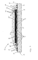
- For a more complete understanding of the invention and the advantages thereof, exemplary embodiments of the invention are explained in more detail in the following description with reference to the accompanying drawing figures, in which like reference characters designate like parts and in which:
- Fig. 1
- is a schematic cross-sectional view of a molding tool system according to a first embodiment of the invention supporting a semi-finished fiber product;
- Fig. 2
- is a schematic cross-sectional view of a molding tool system according to a second embodiment of the invention supporting a semi-finished fiber product;
- Fig. 3
- is a schematic cross-sectional view of a molding tool system according to a third embodiment of the invention supporting a semi-finished fiber product;
- Fig. 4
- is a flow diagram which schematically represents a method according to an embodiment of the invention; and
- Fig. 5
- shows an aircraft according to an embodiment of the invention.
- The accompanying drawings are included to provide a further understanding of the present invention and are incorporated in and constitute a part of this specification. The drawings illustrate particular embodiments of the invention and together with the description serve to explain the principles of the invention. Other embodiments of the invention and many of the attendant advantages of the invention will be readily appreciated as they become better understood with reference to the following detailed description.
- It will be appreciated that common and well understood elements that may be useful or necessary in a commercially feasible embodiment are not necessarily depicted in order to facilitate a less abstracted view of the embodiments. The elements of the drawings are not necessarily illustrated to scale relative to each other. It will further be appreciated that certain actions and/or steps in an embodiment of a method may be described or depicted in a particular order of occurrences while those skilled in the art will understand that such specificity with respect to sequence is not actually required. It will also be understood that the terms and expressions used in the present specification have the ordinary meaning as it accorded to such terms and expressions with respect to their corresponding respective areas of inquiry and study, except where specific meanings have otherwise been set forth herein.
- With reference to
Fig. 1 of the drawings, a cross-sectional view of amolding tool system 1 according to an embodiment of the invention is shown. Themolding tool system 1 naturally includes amolding tool 2 upon which asemi-finished fiber product 3 is supported. Themolding tool 2 of thesystem 1 in this example comprises abase 4, which is preferably formed of metal, but may also be formed of a plastic, a ceramic or another suitable material. Anupper surface 5 of thebase 4 at least partially defines a shape of the component to be produced by impregnating thesemi-finished fiber product 3 with a liquid matrix material, typically resin, then curing same. Grooves orchannels 6 are formed in theupper surface 5 of themolding tool base 4 and are configured to convey or feed or distribute the matrix material more or less uniformly over an area covered by thesemi-finished fiber product 3. In this example the cross-section of each groove orchannel 6 is semi-cylindrical, but it may also be any other desired form. The width of each groove orchannel 6 preferably lies in the range of 0.1 mm to 10 mm, while the depth of each groove orchannel 6 may be of the same order of magnitude. It will be noted that the size and shape of the grooves orchannels 6 can be chosen to influence throughput of the matrix resin. Two or more of the grooves orchannels 6 may also differ in cross-section, geometry, width, and/or arrangement over at least a part of their length or over their entire length. - The
semi-finished fiber product 3 is arranged and supported on themolding tool 2 so as to follow the contours or profile of thesurface 5. Thesemi-finished fiber product 3 may, for example, comprise a laid, woven or knitted fabric, non-woven fabric, loose fibers, and/or a sandwich-like structure (e.g. with a preform core) as a preform stack. A thickness of thesemi-finished fiber product 3 may also vary over theupper surface 5. A peel ply and/or a release film 7 may optionally also be arranged between theupper surface 5 of themolding tool base 4 and thesemi-finished fiber product 3, though this peel ply 7 is unnecessary with the present invention, as will be apparent from the following description. - Before the semi-finished fiber product 3 (with optional peel ply 7) is placed on the
molding tool base 4, a flexible andresilient film 8 with resin release properties (e.g. a plasma treated TPE film) is placed and drawn tautly over theupper surface 5 and is sealed to thebase 4 at itsedges 9. The air between theupper surface 5 and theresilient film 8 is then evacuated by a pump (not shown) so that thefilm 8 is sucked onto or drawn against theupper surface 5 and fully conforms to the contours of themolding tool base 4, including the grooves orchannels 6 such that thefilm 8 forms a lining in each of those grooves orchannels 6. Theresilient film 8 is thereby elastically deformed into a tensioned or stretched state over themolding tool 2, as shown inFig. 1 . - The semi-finished fiber product 3 (i.e. preform stack with optional peel ply or release film 7) is then placed on top of the
film 8 such that it is supported on themolding tool 2 and the entire construction is packed in an airtight manner by means of avacuum bagging films 10 and sealing strips 11. In this regard, it can be expedient to use a double-walled vacuum film 10, as shown inFIG. 1 . In principle, other types of vacuum bagging that are necessary for different processes are also possible (e.g. for introducing membranes in vacuum-assisted processing (VAP) or where the inlet and outlet are identical with single line injection (SLI)). The air enclosed under thevacuum films 10 is then extracted or evacuated by a pump via one ormore connection 12. - An
inlet 13 is connected to a reservoir (not shown) of liquid matrix material, e.g. resin. The resin matrix material is drawn into the bagging formed byvacuum films 10 by virtue of the pressure gradient created by pumpingconnections 12. The matrix resin flows over thefilm 8 on theupper surface 5 of themolding tool base 4 of thesystem 1, and through the semi-finished fiber product or preformstack 3. In so doing, the grooves orchannels 6 act to feed or convey the matrix resin uniformly to thesemi-finished fiber product 3. If using a VAP process, evacuation occurs over the whole surface or outer mold line of the semi-finished fiber product, which may then be thoroughly impregnated with the matrix resin. Excess resin is usually not present, though if it were, is able to be carried away at anoutlet 14 together with any air via thepump connections 12. - The
inlet 13 and/or theoutlet 14 may be incorporated in thebase 4 of themolding tool 2. Alternatively, it is possible to provide them as conventional tubular or local ports which are packed underneath thevacuum film 10, as shown inFig. 1 . Theinlet 13 and theoutlet 14 are preferably arranged in different planes, and preferably also on different sides of thesemi-finished fiber product 3. - Once a sufficient amount of matrix resin has been fed to the
preform stack 3, the introduction or influx of resin matrix material via theinlet 13 can be stopped. The vacuum between theresilient film 8 and themolding tool base 4 can then be removed or terminated, which causes thefilm 8 to relax from its stretched or tensioned state to re-assume an essentially flat condition or configuration. Thus, thefilm 8 is released and, due to both its elastic properties and the vacuum under the bagging 10, thefilm 8 starts to move out of the grooves orchannels 6 towards thepreform 3. Accordingly, thefilm 8 and the matrix resin it carries, is forced out of the grooves orchannels 6 under the combined action of its own elasticity or resilience and the vacuum from the bagging 10. In so doing thefilm 8 lifts or forces the remaining matrix resin out of the grooves orchannels 6 and into thesemi-finished fiber product 3. As theflattening film 8 is impermeable to the matrix resin, theupper surface 5 of thebase 4, including grooves orchannels 6, is entirely free of resin material and the resin that was held in thechannels 6 is now uniformly distributed towards the component being molded. Furthermore, the now flattenedfilm 8 provides a highly smooth surface for curing of the resin. Also, due to the very good release properties of thefilm 8, the separate release layer or peel ply 7 becomes unnecessary and can be omitted. After curing, therefore, theresilient film 8 can be readily released from the component and generates a high quality and very smooth surface. An upper release layer or peel ply 15 between thepreform stack 3 and thevacuum bagging film 10 does remain desirable, however. - With reference now to drawing
Fig. 2 , a cross-sectional view of amolding tool system 1 according to another embodiment is shown. In this embodiment, noresilient film 8 is present, although it may optionally be employed in conjunction with the other features to be described. Each of the channels orgrooves 6 formed in theupper surface 5 of themolding tool 2 in this embodiment has a dove-tailed shape in longitudinal cross-section and includes a respective slider member 16 (of which only 3 are shown). Eachslider member 16 has a shape or cross-section which fits snugly within its corresponding groove orchannel 6 and is sized to be slidably insertable therein. Each of theslider members 16 may be actuated for sliding movement in a respective groove orchannel 6 by air-pressure (pneumatically), hydraulically, thermal expansion, by shape memory materials, by servo or even by hand. - Before conveying or infusion feeding the liquid matrix resin to the
system 1, theslider members 16 are drawn back to open the grooves orchannels 6 to resin flow. In this way, grooves orchannels 6 serve to convey or distribute the liquid matrix resin to the semi-finished fiber product or preformstack 3 in the manner described above. Upon completing an infusion of the matrix resin, however, theslider members 16 are reinserted into thechannels 6. By doing so, matrix resin that remains in the grooves orchannels 6 can be pushed out or expelled therefrom and is forced, at least partially, into the semi-finished fiber product or preformstack 3. At the same time, insertion theslider members 16 also generates an even or flatupper surface 5 on themolding tool 2 again, and after curing, this can further simplify removal or de-molding of the newly fabricated component from thetool 2. To reduce the effort associated with application of release agents to theupper surface 5 and theslider members 16, this technique can be combined with theflexible film 8 described above with reference toFig. 1 . That is, theslider members 16 could be used in combination with thefilm 8 the dove-tail channels 6. - Referring now to
Fig. 3 of the drawings, a cross-sectional view of amolding tool system 1 of a further embodiment is shown. This embodiment again employs a flexible orresilient film 8, but without grooves orchannels 6 formed in abase 4 of themolding tool 2. Rather,upper surface 5 of themolding tool base 4 in this embodiment merely follows the contours or profile desired in the molded component. Instead, therefore, cavities or channels 6' for resin transport are generated by an interaction between thefilm 8 and one ormore element 17, such as a fabric or fleece, placed on and theupper surface 5 of thetool 2 under thefilm 8. After thefilm 8 is arranged flat and taut over thesurface 5 and sealed at itsedges 9, a vacuum is applied between thefilm 8 andupper surface 5 of thetool base 4 as before. Due to the properties of the film, thefilm 8 follows close to the structure of the fabric or fleece (represented here as discrete elements 17) between thefilm 8 andtool base 4 and generates the resin channels 6' desired for conveying the matrix resin. After infusion, the vacuum is released and the structure disappears because thefilm 8 resumes its taut, flat configuration and any matrix resin material remaining in those cavities or channels 6' is forced into the semi-finished fiber product orpreform 3. The curing and de-molding of the component produced then follows the same as for themolding tool system 1 described with reference toFig. 1 . - With reference now to
Fig. 4 of the drawings, an example of a method of producing a fiber composite component according to the invention is illustrated schematically, with the numbered boxes I to IV of the diagram representing steps of the method. The first box I represents the step of providing amolding tool 2 for supporting a semi-finished fiber product orpreform 3 thereon, themolding tool 2 having a plurality of cavities or openings in the form of grooves orchannels 6 for feeding or conveying matrix material to the semi-finished fiber product orpreform 3. The second box II represents the step of feeding or conveying matrix material to the semi-finished fiber product orpreform 3 supported on themolding tool 2 via the plurality of grooves orchannels 6. The third box III represents the step of expelling any matrix material remaining from the grooves orchannels 6 upon conclusion of the feeding step, especially by forcing at least a portion of the matrix material remaining in those grooves orchannels 6 into thesemi-finished fiber product 3. The third box III may thus represent either one or both of: releasing theresilient film 8 from its stretched or tensioned state and/or insertingslider members 16 into the grooves orchannels 6. The fourth box IV represents the steps of curing the semi-finished fiber product orpreform 3 after it has been impregnated with the liquid matrix material to form the fiber composite component, and subsequently removing (i.e. de-molding) that component from themolding tool 2. - Finally, an
aircraft 20 which includes one or more of the fiber composite components produced via a method andmolding tool system 1 of the invention described in detail above with reference toFigs. 1 to 4 is shown schematically inFig. 5 . The one or more fiber composite components are incorporated in a structure of afuselage 21,wings 22,tail 23 and/orhorizontal stabilizers 24 of theaircraft 20. - Although specific embodiments of the invention have been illustrated and described herein, it will be appreciated by those of ordinary skill in the art that a variety of alternate and/or equivalent implementations exist. It should be appreciated that the exemplary embodiment or exemplary embodiments are only examples, and are not intended to limit the scope, applicability, or configuration in any way. Rather, the foregoing summary and detailed description will provide those skilled in the art with a convenient road map for implementing at least one exemplary embodiment, it being understood that various changes may be made in the function and arrangement of elements described in an exemplary embodiment without departing from the scope as set forth in the appended claims and their legal equivalents. Generally, this application is intended to cover any adaptations or variations of the specific embodiments discussed herein.
- In this document, the terms "comprise", "comprising", "include", "including", "contain", "containing", "have", "having", and any variations thereof, are intended to be understood in an inclusive (i.e. non-exclusive) sense, such that the process, method, device, apparatus or system described herein is not limited to those features or parts or elements or steps recited but may include other elements, features, parts or steps not expressly listed or inherent to such process, method, article, or apparatus. Furthermore, the terms "a" and "an" used herein are intended to be understood as meaning one or more unless explicitly stated otherwise. Moreover, the terms "first", "second", "third", etc. are used merely as labels, and are not intended to impose numerical requirements on or to establish a certain ranking of importance of their objects.
-
- 1
- molding tool system
- 2
- molding tool
- 3
- semi-finished fiber product or preform stack
- 4
- molding tool base
- 5
- upper surface of base
- 6
- groove or channel
- 6'
- groove or channel
- 7
- release film or peel ply
- 8
- resilient film
- 9
- sealed edge of resilient film
- 10
- vacuum bagging film
- 11
- sealing strip
- 12
- vacuum pump connection
- 13
- matrix resin inlet
- 14
- matrix resin outlet
- 15
- release film or peel ply
- 16
- slider member
- 17
- element
- 20
- aircraft
- 21
- fuselage
- 22
- wing
- 23
- tail
- 24
- horizontal stabilizer
Claims (15)
- A method of producing a fiber composite component, the method comprising the steps of:providing a molding tool (2) for supporting a semi-finished fiber product (3) thereon, wherein the molding tool provides a plurality of cavities or openings (6, 6') for feeding or conveying matrix material to the semi-finished fiber product (3);feeding matrix material to the semi-finished fiber product supported on the molding tool via the plurality of cavities or openings (6, 6'); andexpelling matrix material remaining in the cavities or openings (6, 6') upon conclusion of the feeding step.
- A method according to claim 1, wherein the expelling step comprises forcing at least a portion of the matrix material remaining in the cavities or openings (6, 6') into the semi-finished fiber product (3).
- A method according to claim 2, wherein the molding tool includes a film (8) that is substantially impermeable to the matrix material, wherein the method includes the step of forming or lining the plurality of cavities or openings (6, 6') in the molding tool (2) with the film (8), and wherein the step of expelling the matrix material includes releasing the film (8) from the cavities or openings (6, 6').
- A method according to claim 3, wherein the step of forming or lining the plurality of cavities or openings (6, 6') in the molding tool with the film (8) comprises holding the film (8) onto or against a surface (5) of the molding tool (2) in a tensioned or stretched state, especially via a vacuum or negative pressure.
- A method according to claim 4, wherein releasing the film from the cavities or openings comprises releasing the film from said stretched or tensioned state.
- A method according to claim 1 or 2, wherein the step of expelling the matrix material comprises introducing a member (16) into each of the respective cavities or openings (6, 6') to displace or dispel the remaining matrix material from the cavities or openings (6, 6').
- A method according to claim 6, wherein the step of introducing the displacement members into the respective cavities or openings essentially closes the cavities or openings to isolate the fiber product therefrom, and/or wherein the displacement members (16) have a shape or form that substantially corresponds to a shape or form of the cavities or openings.
- A method of producing a fiber composite component, the method comprising the steps of:providing a molding tool that supports the semi-finished fiber product on a surface having a plurality of cavities or openings for feeding or distributing matrix material to the semi-finished fiber product;feeding matrix material to the semi-finished fiber product supported on the molding tool via the plurality of cavities or openings; andmodifying said surface of the molding tool to at least partially eliminate, cover, or close said cavities or openings upon conclusion of the feeding step.
- A method according to claim 8, wherein the molding tool is provided with a film substantially impermeable to the matrix material, wherein the method includes the step of forming or lining the plurality of cavities or openings in the molding tool with said film, and wherein the step of modifying the surface of the molding tool includes removing the film from the cavities or openings.
- A method according to any one of claims 1 to 9, wherein the cavities or openings are formed in a surface of the molding tool and are in the form of grooves or channels.
- A molding tool system for producing fiber composite components, the system comprising:a molding tool (2) for supporting a semi-finished fiber product (3), wherein the molding tool (2) provides a plurality of cavities or openings (6, 6') for feeding or conveying matrix material to the semi-finished fiber product (3) supported thereon; andan arrangement (8, 16) configured to expel matrix material remaining in the cavities or openings (6, 6') upon conclusion of feeding of the matrix material.
- A system according to claim 11, wherein the arrangement is configured to force at least a portion of the matrix material remaining in the cavities or openings into the semi-finished fiber product (3) supported on the molding tool.
- A system according to claim 11 or claim 12, wherein the arrangement comprises a film (8) which is substantially impermeable to the matrix material and which forms or lines the cavities or openings (6, 6') in the molding tool 2); and/or wherein the arrangement comprises a plurality of members (16) which are respectively insertable into the plurality of cavities or openings to displace or dispel the remaining matrix material from the cavities or openings.
- A molding tool system (1) for producing fiber composite components, comprising:a molding tool (2) for supporting a semi-finished fiber product (3) on a surface (5) having a plurality of cavities or openings (6, 6') for feeding or conveying matrix material to the semi-finished fiber product supported thereon; andan arrangement (8, 16) configured to modify said surface of the molding tool (2) to at least partially eliminate, cover, or close the cavities or openings (6) upon conclusion of feeding of the matrix material.
- A system according to any of claims 11 to 14, wherein the cavities or openings (6, 6') are formed as grooves or channels in a surface of the molding tool (2).
Priority Applications (1)
| Application Number | Priority Date | Filing Date | Title |
|---|---|---|---|
| EP20120176588 EP2687357B1 (en) | 2012-07-16 | 2012-07-16 | Method and system for producing fiber composite components |
Applications Claiming Priority (1)
| Application Number | Priority Date | Filing Date | Title |
|---|---|---|---|
| EP20120176588 EP2687357B1 (en) | 2012-07-16 | 2012-07-16 | Method and system for producing fiber composite components |
Publications (2)
| Publication Number | Publication Date |
|---|---|
| EP2687357A1 true EP2687357A1 (en) | 2014-01-22 |
| EP2687357B1 EP2687357B1 (en) | 2014-12-24 |
Family
ID=46516591
Family Applications (1)
| Application Number | Title | Priority Date | Filing Date |
|---|---|---|---|
| EP20120176588 Active EP2687357B1 (en) | 2012-07-16 | 2012-07-16 | Method and system for producing fiber composite components |
Country Status (1)
| Country | Link |
|---|---|
| EP (1) | EP2687357B1 (en) |
Cited By (3)
| Publication number | Priority date | Publication date | Assignee | Title |
|---|---|---|---|---|
| US20190152170A1 (en) * | 2017-11-21 | 2019-05-23 | The Boeing Company | Apparatus and method for manufacturing liquid molded composites using a discrete network of tool surface resin distribution grooves |
| WO2020239778A1 (en) * | 2019-05-31 | 2020-12-03 | Airbus Operations Gmbh | Device and method |
| CN113490583A (en) * | 2019-03-27 | 2021-10-08 | 赛峰飞机发动机公司 | Tool for preforming a fiber preform and method for preforming a fiber preform |
Families Citing this family (1)
| Publication number | Priority date | Publication date | Assignee | Title |
|---|---|---|---|---|
| CN106945304A (en) * | 2017-04-05 | 2017-07-14 | 东莞市精海机械设备有限公司 | A method for forming, processing and coating composite materials |
Citations (4)
| Publication number | Priority date | Publication date | Assignee | Title |
|---|---|---|---|---|
| US20020146529A1 (en) * | 1995-03-28 | 2002-10-10 | Lang Eric J. | Channel assisted resin transfer molding |
| US6558590B1 (en) * | 1999-03-18 | 2003-05-06 | David H. Stewart | Method and machine for manufacturing molded structures using zoned pressure molding |
| US6586054B2 (en) * | 2001-04-24 | 2003-07-01 | The United States Of America As Represented By The Secretary Of The Army | Apparatus and method for selectively distributing and controlling a means for impregnation of fibrous articles |
| US20080044506A1 (en) | 2006-08-17 | 2008-02-21 | Airbus Deutschland Gmbh | Tool for the production of fiber composite components |
-
2012
- 2012-07-16 EP EP20120176588 patent/EP2687357B1/en active Active
Patent Citations (5)
| Publication number | Priority date | Publication date | Assignee | Title |
|---|---|---|---|---|
| US20020146529A1 (en) * | 1995-03-28 | 2002-10-10 | Lang Eric J. | Channel assisted resin transfer molding |
| US6558590B1 (en) * | 1999-03-18 | 2003-05-06 | David H. Stewart | Method and machine for manufacturing molded structures using zoned pressure molding |
| US6586054B2 (en) * | 2001-04-24 | 2003-07-01 | The United States Of America As Represented By The Secretary Of The Army | Apparatus and method for selectively distributing and controlling a means for impregnation of fibrous articles |
| US20080044506A1 (en) | 2006-08-17 | 2008-02-21 | Airbus Deutschland Gmbh | Tool for the production of fiber composite components |
| DE102007013987A1 (en) | 2006-08-17 | 2008-02-21 | Airbus Deutschland Gmbh | Molding surface used when making fibrous composite components in aerospace industry, includes diversity of groove types for supply of impregnation material to fibrous blank |
Cited By (5)
| Publication number | Priority date | Publication date | Assignee | Title |
|---|---|---|---|---|
| US20190152170A1 (en) * | 2017-11-21 | 2019-05-23 | The Boeing Company | Apparatus and method for manufacturing liquid molded composites using a discrete network of tool surface resin distribution grooves |
| US10759124B2 (en) * | 2017-11-21 | 2020-09-01 | The Boeing Company | Apparatus and method for manufacturing liquid molded composites using a discrete network of tool surface resin distribution grooves |
| CN113490583A (en) * | 2019-03-27 | 2021-10-08 | 赛峰飞机发动机公司 | Tool for preforming a fiber preform and method for preforming a fiber preform |
| WO2020239778A1 (en) * | 2019-05-31 | 2020-12-03 | Airbus Operations Gmbh | Device and method |
| US11780120B2 (en) | 2019-05-31 | 2023-10-10 | Airbus Operations Gmbh | Device and method |
Also Published As
| Publication number | Publication date |
|---|---|
| EP2687357B1 (en) | 2014-12-24 |
Similar Documents
| Publication | Publication Date | Title |
|---|---|---|
| CN101124079B (en) | Method and device for producing fibre composite moulded bodies by means of vacuum infusion | |
| CN101754849B (en) | Method of using a formable core block for a resin impregnation process | |
| US10807321B2 (en) | Apparatus and method for infiltration of fiber material with resin for the production of a fiber composite component | |
| US9868237B2 (en) | Mold for producing fiber-reinforced components | |
| US6586054B2 (en) | Apparatus and method for selectively distributing and controlling a means for impregnation of fibrous articles | |
| US9205602B2 (en) | Method for producing fiber-reinforced plastic | |
| EP2346674B1 (en) | Reusable infusion bag | |
| CN103958163B (en) | For the manufacture of equipment and the method for parts | |
| EP2681037B1 (en) | Method for producing a fibre composite component | |
| CN1193870C (en) | Method and device for manufacturing fiber-reinforced components by injection molding | |
| CN105555510B (en) | Method of forming composite member and components therefor | |
| JP4903232B2 (en) | Method and apparatus for providing a polymer for use in a vacuum injection method | |
| DK2647492T3 (en) | Resinstrømelement to a vacuum assisted resinoverførselsstøbeproces | |
| US6656411B1 (en) | Grooved core pattern for optimum resin distribution | |
| EP2687357B1 (en) | Method and system for producing fiber composite components | |
| US7189345B2 (en) | Method for vacuum assisted resin transfer molding | |
| US20010009313A1 (en) | Grooved mold apparatus and process for forming fiber reinforced composite structures | |
| US20080044506A1 (en) | Tool for the production of fiber composite components | |
| US20150115501A1 (en) | Process for producing plastic moulded pieces | |
| EP3124220B1 (en) | A method of moulding a composite article and mould | |
| CN110834419A (en) | Device and method for producing a component | |
| CN101300125B (en) | Method for producing laminates by infusion of resin | |
| JP6048967B2 (en) | Manufacturing method and manufacturing apparatus for fiber-reinforced plastic molded body, and elevator wall | |
| CN105522763B (en) | The manufacture method and FRP sandwich structural bodies of FRP sandwich structural bodies | |
| EP3495122A1 (en) | Apparatus and method for manufacturing molded composites using a discrete network of tool surface resin distribution grooves |
Legal Events
| Date | Code | Title | Description |
|---|---|---|---|
| PUAI | Public reference made under article 153(3) epc to a published international application that has entered the european phase |
Free format text: ORIGINAL CODE: 0009012 |
|
| AK | Designated contracting states |
Kind code of ref document: A1 Designated state(s): AL AT BE BG CH CY CZ DE DK EE ES FI FR GB GR HR HU IE IS IT LI LT LU LV MC MK MT NL NO PL PT RO RS SE SI SK SM TR |
|
| AX | Request for extension of the european patent |
Extension state: BA ME |
|
| 17P | Request for examination filed |
Effective date: 20140423 |
|
| RBV | Designated contracting states (corrected) |
Designated state(s): AL AT BE BG CH CY CZ DE DK EE ES FI FR GB GR HR HU IE IS IT LI LT LU LV MC MK MT NL NO PL PT RO RS SE SI SK SM TR |
|
| 17Q | First examination report despatched |
Effective date: 20140519 |
|
| GRAP | Despatch of communication of intention to grant a patent |
Free format text: ORIGINAL CODE: EPIDOSNIGR1 |
|
| INTG | Intention to grant announced |
Effective date: 20140917 |
|
| GRAS | Grant fee paid |
Free format text: ORIGINAL CODE: EPIDOSNIGR3 |
|
| GRAA | (expected) grant |
Free format text: ORIGINAL CODE: 0009210 |
|
| AK | Designated contracting states |
Kind code of ref document: B1 Designated state(s): AL AT BE BG CH CY CZ DE DK EE ES FI FR GB GR HR HU IE IS IT LI LT LU LV MC MK MT NL NO PL PT RO RS SE SI SK SM TR |
|
| REG | Reference to a national code |
Ref country code: GB Ref legal event code: FG4D |
|
| REG | Reference to a national code |
Ref country code: CH Ref legal event code: EP |
|
| REG | Reference to a national code |
Ref country code: IE Ref legal event code: FG4D |
|
| REG | Reference to a national code |
Ref country code: AT Ref legal event code: REF Ref document number: 702912 Country of ref document: AT Kind code of ref document: T Effective date: 20150115 |
|
| REG | Reference to a national code |
Ref country code: DE Ref legal event code: R096 Ref document number: 602012004467 Country of ref document: DE Effective date: 20150219 |
|
| REG | Reference to a national code |
Ref country code: NL Ref legal event code: VDEP Effective date: 20141224 |
|
| PG25 | Lapsed in a contracting state [announced via postgrant information from national office to epo] |
Ref country code: LT Free format text: LAPSE BECAUSE OF FAILURE TO SUBMIT A TRANSLATION OF THE DESCRIPTION OR TO PAY THE FEE WITHIN THE PRESCRIBED TIME-LIMIT Effective date: 20141224 Ref country code: FI Free format text: LAPSE BECAUSE OF FAILURE TO SUBMIT A TRANSLATION OF THE DESCRIPTION OR TO PAY THE FEE WITHIN THE PRESCRIBED TIME-LIMIT Effective date: 20141224 Ref country code: NO Free format text: LAPSE BECAUSE OF FAILURE TO SUBMIT A TRANSLATION OF THE DESCRIPTION OR TO PAY THE FEE WITHIN THE PRESCRIBED TIME-LIMIT Effective date: 20150324 |
|
| REG | Reference to a national code |
Ref country code: LT Ref legal event code: MG4D |
|
| PG25 | Lapsed in a contracting state [announced via postgrant information from national office to epo] |
Ref country code: HR Free format text: LAPSE BECAUSE OF FAILURE TO SUBMIT A TRANSLATION OF THE DESCRIPTION OR TO PAY THE FEE WITHIN THE PRESCRIBED TIME-LIMIT Effective date: 20141224 Ref country code: GR Free format text: LAPSE BECAUSE OF FAILURE TO SUBMIT A TRANSLATION OF THE DESCRIPTION OR TO PAY THE FEE WITHIN THE PRESCRIBED TIME-LIMIT Effective date: 20150325 Ref country code: RS Free format text: LAPSE BECAUSE OF FAILURE TO SUBMIT A TRANSLATION OF THE DESCRIPTION OR TO PAY THE FEE WITHIN THE PRESCRIBED TIME-LIMIT Effective date: 20141224 Ref country code: SE Free format text: LAPSE BECAUSE OF FAILURE TO SUBMIT A TRANSLATION OF THE DESCRIPTION OR TO PAY THE FEE WITHIN THE PRESCRIBED TIME-LIMIT Effective date: 20141224 Ref country code: LV Free format text: LAPSE BECAUSE OF FAILURE TO SUBMIT A TRANSLATION OF THE DESCRIPTION OR TO PAY THE FEE WITHIN THE PRESCRIBED TIME-LIMIT Effective date: 20141224 |
|
| REG | Reference to a national code |
Ref country code: AT Ref legal event code: MK05 Ref document number: 702912 Country of ref document: AT Kind code of ref document: T Effective date: 20141224 |
|
| REG | Reference to a national code |
Ref country code: FR Ref legal event code: PLFP Year of fee payment: 4 |
|
| PG25 | Lapsed in a contracting state [announced via postgrant information from national office to epo] |
Ref country code: NL Free format text: LAPSE BECAUSE OF FAILURE TO SUBMIT A TRANSLATION OF THE DESCRIPTION OR TO PAY THE FEE WITHIN THE PRESCRIBED TIME-LIMIT Effective date: 20141224 |
|
| PG25 | Lapsed in a contracting state [announced via postgrant information from national office to epo] |
Ref country code: CZ Free format text: LAPSE BECAUSE OF FAILURE TO SUBMIT A TRANSLATION OF THE DESCRIPTION OR TO PAY THE FEE WITHIN THE PRESCRIBED TIME-LIMIT Effective date: 20141224 Ref country code: EE Free format text: LAPSE BECAUSE OF FAILURE TO SUBMIT A TRANSLATION OF THE DESCRIPTION OR TO PAY THE FEE WITHIN THE PRESCRIBED TIME-LIMIT Effective date: 20141224 Ref country code: SK Free format text: LAPSE BECAUSE OF FAILURE TO SUBMIT A TRANSLATION OF THE DESCRIPTION OR TO PAY THE FEE WITHIN THE PRESCRIBED TIME-LIMIT Effective date: 20141224 Ref country code: RO Free format text: LAPSE BECAUSE OF FAILURE TO SUBMIT A TRANSLATION OF THE DESCRIPTION OR TO PAY THE FEE WITHIN THE PRESCRIBED TIME-LIMIT Effective date: 20141224 Ref country code: ES Free format text: LAPSE BECAUSE OF FAILURE TO SUBMIT A TRANSLATION OF THE DESCRIPTION OR TO PAY THE FEE WITHIN THE PRESCRIBED TIME-LIMIT Effective date: 20141224 |
|
| PG25 | Lapsed in a contracting state [announced via postgrant information from national office to epo] |
Ref country code: AT Free format text: LAPSE BECAUSE OF FAILURE TO SUBMIT A TRANSLATION OF THE DESCRIPTION OR TO PAY THE FEE WITHIN THE PRESCRIBED TIME-LIMIT Effective date: 20141224 Ref country code: IS Free format text: LAPSE BECAUSE OF FAILURE TO SUBMIT A TRANSLATION OF THE DESCRIPTION OR TO PAY THE FEE WITHIN THE PRESCRIBED TIME-LIMIT Effective date: 20150424 Ref country code: PL Free format text: LAPSE BECAUSE OF FAILURE TO SUBMIT A TRANSLATION OF THE DESCRIPTION OR TO PAY THE FEE WITHIN THE PRESCRIBED TIME-LIMIT Effective date: 20141224 |
|
| REG | Reference to a national code |
Ref country code: DE Ref legal event code: R097 Ref document number: 602012004467 Country of ref document: DE |
|
| PG25 | Lapsed in a contracting state [announced via postgrant information from national office to epo] |
Ref country code: DK Free format text: LAPSE BECAUSE OF FAILURE TO SUBMIT A TRANSLATION OF THE DESCRIPTION OR TO PAY THE FEE WITHIN THE PRESCRIBED TIME-LIMIT Effective date: 20141224 |
|
| PLBE | No opposition filed within time limit |
Free format text: ORIGINAL CODE: 0009261 |
|
| STAA | Information on the status of an ep patent application or granted ep patent |
Free format text: STATUS: NO OPPOSITION FILED WITHIN TIME LIMIT |
|
| 26N | No opposition filed |
Effective date: 20150925 |
|
| PG25 | Lapsed in a contracting state [announced via postgrant information from national office to epo] |
Ref country code: IT Free format text: LAPSE BECAUSE OF FAILURE TO SUBMIT A TRANSLATION OF THE DESCRIPTION OR TO PAY THE FEE WITHIN THE PRESCRIBED TIME-LIMIT Effective date: 20141224 |
|
| PG25 | Lapsed in a contracting state [announced via postgrant information from national office to epo] |
Ref country code: MC Free format text: LAPSE BECAUSE OF FAILURE TO SUBMIT A TRANSLATION OF THE DESCRIPTION OR TO PAY THE FEE WITHIN THE PRESCRIBED TIME-LIMIT Effective date: 20141224 Ref country code: SI Free format text: LAPSE BECAUSE OF FAILURE TO SUBMIT A TRANSLATION OF THE DESCRIPTION OR TO PAY THE FEE WITHIN THE PRESCRIBED TIME-LIMIT Effective date: 20141224 |
|
| REG | Reference to a national code |
Ref country code: CH Ref legal event code: PL |
|
| PG25 | Lapsed in a contracting state [announced via postgrant information from national office to epo] |
Ref country code: LU Free format text: LAPSE BECAUSE OF FAILURE TO SUBMIT A TRANSLATION OF THE DESCRIPTION OR TO PAY THE FEE WITHIN THE PRESCRIBED TIME-LIMIT Effective date: 20150716 |
|
| REG | Reference to a national code |
Ref country code: IE Ref legal event code: MM4A |
|
| PG25 | Lapsed in a contracting state [announced via postgrant information from national office to epo] |
Ref country code: CH Free format text: LAPSE BECAUSE OF NON-PAYMENT OF DUE FEES Effective date: 20150731 Ref country code: LI Free format text: LAPSE BECAUSE OF NON-PAYMENT OF DUE FEES Effective date: 20150731 |
|
| PG25 | Lapsed in a contracting state [announced via postgrant information from national office to epo] |
Ref country code: BE Free format text: LAPSE BECAUSE OF FAILURE TO SUBMIT A TRANSLATION OF THE DESCRIPTION OR TO PAY THE FEE WITHIN THE PRESCRIBED TIME-LIMIT Effective date: 20141224 |
|
| REG | Reference to a national code |
Ref country code: FR Ref legal event code: PLFP Year of fee payment: 5 |
|
| PG25 | Lapsed in a contracting state [announced via postgrant information from national office to epo] |
Ref country code: IE Free format text: LAPSE BECAUSE OF NON-PAYMENT OF DUE FEES Effective date: 20150716 |
|
| PGFP | Annual fee paid to national office [announced via postgrant information from national office to epo] |
Ref country code: GB Payment date: 20160721 Year of fee payment: 5 |
|
| PG25 | Lapsed in a contracting state [announced via postgrant information from national office to epo] |
Ref country code: MT Free format text: LAPSE BECAUSE OF FAILURE TO SUBMIT A TRANSLATION OF THE DESCRIPTION OR TO PAY THE FEE WITHIN THE PRESCRIBED TIME-LIMIT Effective date: 20141224 |
|
| PG25 | Lapsed in a contracting state [announced via postgrant information from national office to epo] |
Ref country code: SM Free format text: LAPSE BECAUSE OF FAILURE TO SUBMIT A TRANSLATION OF THE DESCRIPTION OR TO PAY THE FEE WITHIN THE PRESCRIBED TIME-LIMIT Effective date: 20141224 Ref country code: HU Free format text: LAPSE BECAUSE OF FAILURE TO SUBMIT A TRANSLATION OF THE DESCRIPTION OR TO PAY THE FEE WITHIN THE PRESCRIBED TIME-LIMIT; INVALID AB INITIO Effective date: 20120716 Ref country code: BG Free format text: LAPSE BECAUSE OF FAILURE TO SUBMIT A TRANSLATION OF THE DESCRIPTION OR TO PAY THE FEE WITHIN THE PRESCRIBED TIME-LIMIT Effective date: 20141224 |
|
| PG25 | Lapsed in a contracting state [announced via postgrant information from national office to epo] |
Ref country code: CY Free format text: LAPSE BECAUSE OF FAILURE TO SUBMIT A TRANSLATION OF THE DESCRIPTION OR TO PAY THE FEE WITHIN THE PRESCRIBED TIME-LIMIT Effective date: 20141224 |
|
| REG | Reference to a national code |
Ref country code: FR Ref legal event code: PLFP Year of fee payment: 6 |
|
| GBPC | Gb: european patent ceased through non-payment of renewal fee |
Effective date: 20170716 |
|
| PG25 | Lapsed in a contracting state [announced via postgrant information from national office to epo] |
Ref country code: GB Free format text: LAPSE BECAUSE OF NON-PAYMENT OF DUE FEES Effective date: 20170716 |
|
| PG25 | Lapsed in a contracting state [announced via postgrant information from national office to epo] |
Ref country code: MK Free format text: LAPSE BECAUSE OF FAILURE TO SUBMIT A TRANSLATION OF THE DESCRIPTION OR TO PAY THE FEE WITHIN THE PRESCRIBED TIME-LIMIT Effective date: 20141224 Ref country code: TR Free format text: LAPSE BECAUSE OF FAILURE TO SUBMIT A TRANSLATION OF THE DESCRIPTION OR TO PAY THE FEE WITHIN THE PRESCRIBED TIME-LIMIT Effective date: 20141224 |
|
| REG | Reference to a national code |
Ref country code: FR Ref legal event code: PLFP Year of fee payment: 7 |
|
| PG25 | Lapsed in a contracting state [announced via postgrant information from national office to epo] |
Ref country code: PT Free format text: LAPSE BECAUSE OF FAILURE TO SUBMIT A TRANSLATION OF THE DESCRIPTION OR TO PAY THE FEE WITHIN THE PRESCRIBED TIME-LIMIT Effective date: 20141224 |
|
| PG25 | Lapsed in a contracting state [announced via postgrant information from national office to epo] |
Ref country code: AL Free format text: LAPSE BECAUSE OF FAILURE TO SUBMIT A TRANSLATION OF THE DESCRIPTION OR TO PAY THE FEE WITHIN THE PRESCRIBED TIME-LIMIT Effective date: 20141224 |
|
| PGFP | Annual fee paid to national office [announced via postgrant information from national office to epo] |
Ref country code: DE Payment date: 20250722 Year of fee payment: 14 |
|
| PGFP | Annual fee paid to national office [announced via postgrant information from national office to epo] |
Ref country code: FR Payment date: 20250725 Year of fee payment: 14 |