EP2687171A1 - Polyaxial bone anchoring device - Google Patents
Polyaxial bone anchoring device Download PDFInfo
- Publication number
- EP2687171A1 EP2687171A1 EP12176959.0A EP12176959A EP2687171A1 EP 2687171 A1 EP2687171 A1 EP 2687171A1 EP 12176959 A EP12176959 A EP 12176959A EP 2687171 A1 EP2687171 A1 EP 2687171A1
- Authority
- EP
- European Patent Office
- Prior art keywords
- receiving part
- bone anchoring
- head
- anchoring device
- pressure element
- Prior art date
- Legal status (The legal status is an assumption and is not a legal conclusion. Google has not performed a legal analysis and makes no representation as to the accuracy of the status listed.)
- Granted
Links
Images



Classifications
-
- A—HUMAN NECESSITIES
- A61—MEDICAL OR VETERINARY SCIENCE; HYGIENE
- A61B—DIAGNOSIS; SURGERY; IDENTIFICATION
- A61B17/00—Surgical instruments, devices or methods
- A61B17/56—Surgical instruments or methods for treatment of bones or joints; Devices specially adapted therefor
- A61B17/58—Surgical instruments or methods for treatment of bones or joints; Devices specially adapted therefor for osteosynthesis, e.g. bone plates, screws or setting implements
- A61B17/68—Internal fixation devices, including fasteners and spinal fixators, even if a part thereof projects from the skin
- A61B17/70—Spinal positioners or stabilisers, e.g. stabilisers comprising fluid filler in an implant
- A61B17/7001—Screws or hooks combined with longitudinal elements which do not contact vertebrae
- A61B17/7032—Screws or hooks with U-shaped head or back through which longitudinal rods pass
-
- A—HUMAN NECESSITIES
- A61—MEDICAL OR VETERINARY SCIENCE; HYGIENE
- A61B—DIAGNOSIS; SURGERY; IDENTIFICATION
- A61B17/00—Surgical instruments, devices or methods
- A61B17/56—Surgical instruments or methods for treatment of bones or joints; Devices specially adapted therefor
- A61B17/58—Surgical instruments or methods for treatment of bones or joints; Devices specially adapted therefor for osteosynthesis, e.g. bone plates, screws or setting implements
- A61B17/68—Internal fixation devices, including fasteners and spinal fixators, even if a part thereof projects from the skin
- A61B17/70—Spinal positioners or stabilisers, e.g. stabilisers comprising fluid filler in an implant
- A61B17/7001—Screws or hooks combined with longitudinal elements which do not contact vertebrae
- A61B17/7035—Screws or hooks, wherein a rod-clamping part and a bone-anchoring part can pivot relative to each other
- A61B17/7037—Screws or hooks, wherein a rod-clamping part and a bone-anchoring part can pivot relative to each other wherein pivoting is blocked when the rod is clamped
-
- A—HUMAN NECESSITIES
- A61—MEDICAL OR VETERINARY SCIENCE; HYGIENE
- A61B—DIAGNOSIS; SURGERY; IDENTIFICATION
- A61B17/00—Surgical instruments, devices or methods
- A61B17/56—Surgical instruments or methods for treatment of bones or joints; Devices specially adapted therefor
- A61B17/58—Surgical instruments or methods for treatment of bones or joints; Devices specially adapted therefor for osteosynthesis, e.g. bone plates, screws or setting implements
- A61B17/68—Internal fixation devices, including fasteners and spinal fixators, even if a part thereof projects from the skin
- A61B17/70—Spinal positioners or stabilisers, e.g. stabilisers comprising fluid filler in an implant
- A61B17/7001—Screws or hooks combined with longitudinal elements which do not contact vertebrae
- A61B17/7035—Screws or hooks, wherein a rod-clamping part and a bone-anchoring part can pivot relative to each other
-
- A—HUMAN NECESSITIES
- A61—MEDICAL OR VETERINARY SCIENCE; HYGIENE
- A61B—DIAGNOSIS; SURGERY; IDENTIFICATION
- A61B17/00—Surgical instruments, devices or methods
- A61B17/56—Surgical instruments or methods for treatment of bones or joints; Devices specially adapted therefor
- A61B17/58—Surgical instruments or methods for treatment of bones or joints; Devices specially adapted therefor for osteosynthesis, e.g. bone plates, screws or setting implements
- A61B17/68—Internal fixation devices, including fasteners and spinal fixators, even if a part thereof projects from the skin
- A61B17/70—Spinal positioners or stabilisers, e.g. stabilisers comprising fluid filler in an implant
- A61B17/7049—Connectors, not bearing on the vertebrae, for linking longitudinal elements together
-
- A—HUMAN NECESSITIES
- A61—MEDICAL OR VETERINARY SCIENCE; HYGIENE
- A61B—DIAGNOSIS; SURGERY; IDENTIFICATION
- A61B17/00—Surgical instruments, devices or methods
- A61B17/56—Surgical instruments or methods for treatment of bones or joints; Devices specially adapted therefor
- A61B17/58—Surgical instruments or methods for treatment of bones or joints; Devices specially adapted therefor for osteosynthesis, e.g. bone plates, screws or setting implements
- A61B17/68—Internal fixation devices, including fasteners and spinal fixators, even if a part thereof projects from the skin
- A61B2017/681—Alignment, compression, or distraction mechanisms
-
- A—HUMAN NECESSITIES
- A61—MEDICAL OR VETERINARY SCIENCE; HYGIENE
- A61B—DIAGNOSIS; SURGERY; IDENTIFICATION
- A61B17/00—Surgical instruments, devices or methods
- A61B17/56—Surgical instruments or methods for treatment of bones or joints; Devices specially adapted therefor
- A61B17/58—Surgical instruments or methods for treatment of bones or joints; Devices specially adapted therefor for osteosynthesis, e.g. bone plates, screws or setting implements
- A61B17/68—Internal fixation devices, including fasteners and spinal fixators, even if a part thereof projects from the skin
- A61B17/84—Fasteners therefor or fasteners being internal fixation devices
- A61B17/86—Pins or screws or threaded wires; nuts therefor
- A61B17/8665—Nuts
- A61B2017/867—Nuts with integral locking or clamping means
- A61B2017/8675—Nuts with integral locking or clamping means clamping effect due to tapering, e.g. conical thread
-
- A—HUMAN NECESSITIES
- A61—MEDICAL OR VETERINARY SCIENCE; HYGIENE
- A61F—FILTERS IMPLANTABLE INTO BLOOD VESSELS; PROSTHESES; DEVICES PROVIDING PATENCY TO, OR PREVENTING COLLAPSING OF, TUBULAR STRUCTURES OF THE BODY, e.g. STENTS; ORTHOPAEDIC, NURSING OR CONTRACEPTIVE DEVICES; FOMENTATION; TREATMENT OR PROTECTION OF EYES OR EARS; BANDAGES, DRESSINGS OR ABSORBENT PADS; FIRST-AID KITS
- A61F2/00—Filters implantable into blood vessels; Prostheses, i.e. artificial substitutes or replacements for parts of the body; Appliances for connecting them with the body; Devices providing patency to, or preventing collapsing of, tubular structures of the body, e.g. stents
- A61F2/02—Prostheses implantable into the body
- A61F2/30—Joints
- A61F2002/30001—Additional features of subject-matter classified in A61F2/28, A61F2/30 and subgroups thereof
- A61F2002/30316—The prosthesis having different structural features at different locations within the same prosthesis; Connections between prosthetic parts; Special structural features of bone or joint prostheses not otherwise provided for
- A61F2002/30329—Connections or couplings between prosthetic parts, e.g. between modular parts; Connecting elements
- A61F2002/30476—Connections or couplings between prosthetic parts, e.g. between modular parts; Connecting elements locked by an additional locking mechanism
- A61F2002/30495—Connections or couplings between prosthetic parts, e.g. between modular parts; Connecting elements locked by an additional locking mechanism using a locking ring
Definitions
- the invention relates to a polyaxial bone anchoring device that includes a bone anchoring element with a head and a shank and a receiving part for coupling the bone anchoring element to a rod.
- a pressure element is provided that comprises flexible sections each having an inclined surface portion that cooperates with a corresponding inclined surface portion provided at the receiving part in a configuration in which the flexible sections are flexed to hold the head in an angular position with low friction before the head is locked.
- US 2010/0234902 A1 describes a receiving part for receiving a rod for coupling the rod to a bone anchoring element.
- the receiving part includes an accommodation space for accommodating a head of a bone anchoring element and a pressure element arranged at least partially in the accommodation space.
- the pressure element has two upstanding resilient fingers and the receiving part comprises two pins to secure the pressure element in the receiving part.
- the pins form an abutment for the fingers of the pressure element when the pressure element is in a position beneath the pins and the resilient fingers assume their unflexed condition. In this configuration the pressure element exerts a pre-stress or pre-load onto the head that provides a friction fit of the head in the receiving part.
- the polyaxial bone anchoring device comprises a pressure element that is designed to achieve a friction fit of the head in the receiving part with a low frictional force. This improves the handling of the device during surgery because the receiving part can be pivoted relative to the bone anchoring element by applying a force, for example manually, to the receiving part to align it with the rod to be inserted.
- the head and the pressure element can be balanced in such a way that a defined pre-load is exerted onto the head. Furthermore, the pre-load exerted via the pressure element onto the head is reproducible, i.e. does not depend on exact dimensions and exact relative positions of the pressure element and the receiving part.
- the polyaxial bone anchoring device can be designed as a polyaxial bone anchoring device with an enlarged pivot angle of the anchoring element relative to the receiving part.
- the head of the bone anchoring element is seated in a sleeve-like insert piece that is rotatably and pivotably accommodated in the receiving part.
- the chain of tolerances includes also the sleeve-like insert piece.
- a polyaxial bone anchoring device includes a bone anchoring element 1 in the form of a bone screw having a shank 2 with a threaded portion and a head 3.
- the head 3 typically has a spherically-shaped outer surface portion and a recess 3a at its free end for engagement with a driver or another tool.
- the head 3 may be held in a receiving part 4 that couples the bone anchoring element 1 to a stabilization rod 100.
- a sleeve-like insert piece 5 providing a seat for the head 3 and a pressure element 6 for exerting pressure onto the head 3 are arranged.
- a fixation element in the form of, for example, a fixation screw 7 is provided for securing and fixing the rod 100 in the receiving part 4.
- the receiving part 4 has a top end 4a and a bottom end 4b, a central axis C and a coaxial bore 8 extending from the top end 4a in the direction of the bottom end 4b. Adjacent to the top end 4a, a substantially U-shaped recess 9 is provided that forms a channel for receiving the rod 100. By means of the recess 9, two free legs are formed which are provided with an internal thread 10 for cooperating with the fixation screw 7.
- the coaxial bore 8 opens into an accommodation space 11 provided in a lower part of the receiving part, e.g. nearer to the bottom end 4b.
- the accommodation space 11 has a lower opening 12 at the bottom end 4b of the receiving part.
- the accommodation space 11 further includes a seat portion 13 near the bottom end 4b of the receiving part in which the sleeve-like insert piece 5 may be seated.
- the seat portion 13 has a spherical shape in order to provide a socket for a ball and socket joint that is formed by the sleeve-like insert piece 5 and the receiving part 4. It should be noted that the seat portion 13 can also be tapered, or can have various other shapes that can be used to realize a ball and socket joint.
- An inner diameter of the lower opening 12 is smaller than an inner diameter of other portions of the accommodation space 11.
- an inner diameter of the coaxial bore 8 can vary such that the coaxial bore 8 may have different portions with different diameters.
- the receiving part has in the inner wall of the coaxial bore and the accommodation space 11 two recesses 14a, 14b.
- the recesses 14a, 14b are aligned with the U-shaped recess 9 and extend from a bottom of the U-shaped recess 9 into the accommodation space 11.
- the size of the recesses 14a, 14b is such that the sleeve-like insert piece can be introduced from the top end 4a in a 90° tilted position, i.e. the width of the recesses 14a, 14b are greater than the height of the sleeve-like insert piece 5 in its axial direction.
- the recesses 14a, 14b extend into the accommodation space 11 to such an extent the tilting of the insert piece into the seat 13 is possible.
- the receiving part 4 comprises a conically shaped cutout 15 that extends in circumferential direction and is provided in both legs of the receiving part 4.
- the cutout 15 is located at an axial position with respect to the central axis C that is between the accommodation space 11 and the internal thread 10.
- the orientation of the conical cutout 15 is such that the cutout 15 widens in a direction towards the bottom end 4b, thereby providing on each leg a conically inclined surface portion 15a, 15b including an angle of inclination ⁇ with the central axis C.
- the angle of inclination ⁇ may be, for example, approximately 25° ( Fig. 11b ) or at least less than 70°.
- a base surface 15c of the conical cutout may be oriented perpendicular to the central axis C.
- a maximum depth of the cutout 15 in a radial direction may be larger the inner diameter of the bore 8.
- an undercut portion 16 may be provided with an internal diameter that is larger than the inner diameter of the upper edge of the conical cutout 15.
- the sleeve-like insert piece 5 is shown in particular in Figs. 1 and 6 .
- the sleeve-insert piece 5 has an upper edge 5a and a lower edge 5b. Between the upper edge 5a and the lower edge 5b, a sleeve-like insert piece 5 may have a spherically-shaped outer surface portion 51. A largest outer diameter of the sleeve-like insert piece is greater than the inner diameter of the lower opening 12 of the receiving part 4. Hence, the sleeve-like insert piece 5 cannot escape through the lower opening 12 when it is seated in the receiving part 4.
- the dimension or shape of the outer spherical surface portion 51 corresponds to that of the spherically-shaped seat portion 13 in the receiving part 4 in such a way that the sleeve-like insert piece 5 can pivot and rotate in the receiving part 4 when the insert piece 5 is seated in the seat portion 13.
- the lower edge 5b projects out of a lower opening 12 as can be seen in Fig. 11a .
- the sleeve-like insert piece 5 is pivoted or angled in the receiving part, at least a portion of the lower edge 5b still projects out of the lower opening 12.
- the sleeve-insert piece 5 is hollow and has a central portion 52 that is spherically-shaped with a radius corresponding to a radius of the spherically-shaped outer surface portion of the head 3 of the bone anchoring element 1.
- a lower end of the central portion 52 forms a shoulder 53, an inner diameter of the shoulder 53 is smaller than a largest outer diameter of the spherical head 3, so that the head 3 can rotate and pivot in the central spherical portion 52 of the sleeve-like insert piece 5, similar to a ball and socket joint.
- a tapered portion 54 is provided that tapers outward to allow angulation of the bone anchoring element 1 until the shank 2 comes into contact with the lower edge 5b.
- a tapered portion 55 is provided which also tapers outward.
- An inner diameter of tapered portion 55 and of a transition between the tapered portion 55 and the spherical central portion 52 are greater than the largest outer diameter of the head 3, so that the head 3 can be inserted from the upper edge 5a.
- a height of the sleeve-like insert piece 5 in an axial direction is less than a height of the head 3 in an axial direction, such that when the head 3 is inserted into the sleeve-like insert piece 5, a portion of the spherical outer surface of the head 3 still projects from the upper edge 5a of the sleeve-like insert piece 5.
- the pressure element 6 comprises a main body with a first cylindrical portion 61 with a first outer diameter and a second cylindrical portion 62 with a second outer diameter that is smaller than the first outer diameter.
- the first cylindrical portion 61 defines an upper surface 6a and the second cylindrical portion 62 defines a lower edge 6b.
- a spherical recess 63 is provided adjacent to the lower portion 6b.
- the recess 63 is sized such that it matches the shape of the spherical portion of the head 3.
- a coaxial through hole 64 extends from the upper surface 6a into the recess 63 to allow the access with a tool to engage the recess 4 in the head 3 of the bone anchoring element 1.
- a shallow substantially cylinder segment-shaped recess 65 may be provided for guiding the rod.
- the pressure element further comprises flexible sections in the form of two upstanding resilient fingers 66a, 66b extending from the upper surface 6a upwards.
- the outer wall of the resilient fingers 66a, 66b is adjacent to the top surface 6a substantially flush with the outer surface of the first cylindrical portion 61.
- the inner surface of the resilient fingers 66a, 66b is slightly concave in a portion adjacent to the upper surface 6a and substantially straight in a portion adjacent to the free end of the fingers.
- the fingers 66a, 66b each comprise an outwardly extending portion 67a, 67b, respectively, including a top surface 68a, 68b that extends substantially perpendicular to the central axis C and an outer conically inclined surface portion 69a, 69b wherein the cone widens towards the lower edge 6b.
- the angle of inclination of the inclined surface portion 69a, 69b with the central axis C is substantially 25°. It can be smaller than the angle of inclination ⁇ of the inclined surface portions 15a, 15b of the receiving part or can be substantially the same.
- the outwardly extending portion 67a, 67b further comprises a downwardly facing surface 70a, 70b with an inclination opposite to the inclination of the inclined surface portion 69a, 69b that facilitates the insertion of the pressure element into the receiving part 4.
- the dimensions of the pressure element 6 are such that the first outer diameter of the first cylindrical portion 61 is only slightly smaller than the inner diameter of the coaxial bore 8 so that the pressure element can slide along the inner wall of the coaxial bore 8.
- the thickness of the resilient fingers 66a, 66b in a radial direction is smallest at a position at substantially the middle between the top surface 68a, 68b of the fingers and the top surface 6a of the first cylindrical portion 61.
- the resilient fingers 66a, 66b are flexible towards the central axis C in such a manner that they can be slightly bent towards each other as shown in Fig. 10 .
- the height of the resilient fingers 66a, 66b is such that the inclined surface portion 69a, 69b engages an upper portion of the inclined surface portion 15a, 15b of the conical cutout 15, respectively, as shown in Fig. 11a .
- the bone anchoring device as a whole or in parts, is made of a bio-compatible material, such as a bio-compatible metal, for example titanium or stainless steel, a bio-compatible alloy such as Nitinol, or of bio-compatible plastic materials, such as for example, polyetheretherketone (PEEK).
- a bio-compatible material such as a bio-compatible metal, for example titanium or stainless steel, a bio-compatible alloy such as Nitinol, or of bio-compatible plastic materials, such as for example, polyetheretherketone (PEEK).
- PEEK polyetheretherketone
- the polyaxial bone anchoring device may be pre-assembled.
- the steps of assembling the anchoring device are described.
- the sleeve-like insert piece 5 may be introduced from the top end 4a into the receiving part 4 in such a manner that the sleeve-like insert piece is tilted by 90° and then introduced into the receiving part so that it extends into recesses 14a, 14b and thereafter is tilted to assume its position in the seat portion 13.
- the bone anchoring element may be inserted so that the head 3 is seated in the spherical central portion 52 of the sleeve-like insert piece 5.
- the pressure element is inserted from the top end 4a with an orientation such that the resilient fingers are arranged in the U-shaped recess. Then, the pressure element is rotated so that its shallow recess 65 is aligned with the U-shaped recess 9 of the receiving part.
- the resilient fingers 66a, 66b are moved into the conical cutout 15. When the inclined portions 69a, 69b of the resilient fingers engage the inclined surface portion 15a, 15b of the cutout 15, the fingers are slightly bent inward. Because in this configuration, the resilient fingers 66a, 66b tend to move apart from each other, a counterforce is generated when the inclined surface portion 69a, 69b contacts the inclined surface portion 15a of the cutout, respectively, as shown in Fig. 11a .
- the inclined surface portion 69a, 69b can move along the inclined surface portion 15a, 15b when the pressure element is moved downward.
- the dimensional tolerances between the head, the sleeve-like insert piece and the pressure element can be balanced by appropriate positioning of the pressure element 6. Therefore, a reproducible, low friction force acting onto the head is generated.
- the pressure element may additionally be secured against escaping through the top end 4a.
- the securing can be achieved by crimping (not shown). This may prevent that the pressure element 6 is pushed out through the top end 4a because the elastic deformation of the fingers and the generated low friction force may not be sufficient to hold the pressure element in the receiving part in the pre-assembled state.
- the pre-assembled polyaxial bone anchoring device is inserted into a bone or a vertebra.
- at least two bone anchoring devices are used and connected with the rod 100.
- the receiving parts are aligned by rotating and/or pivoting them with respect to the bone anchoring elements.
- the pre-load exerted onto the head can be overcome by manually rotating and/or pivoting the receiving part. Because of the low friction between the head and the pressure element, the anchoring device is convenient to handle.
- the polyaxial bone anchoring device has an enlarged range of angulation that can be achieved at any position within 360° of the receiving part 4 with respect to the bone anchoring element 1.
- the shank 2 of the bone anchoring element 1 comes into contact with the lower edge 5b of the sleeve-like insert piece, the sleeve-like insert piece 5 is also pivoted with the bone anchoring element 1.
- the shank 2 may push the insert piece 5 until the shank 2 abuts against the edge of the lower opening 12 of the receiving part 4.
- the maximum pivot angle that can be achieved depends on the dimensions of the sleeve-like insert piece 5, the receiving part 4 and the bone anchoring element 1, but is typically equal to or greater than 45° measured from a straight or zero angle position between the receiving part 4 and the bone anchoring element 1.
- the rod 100 is inserted into the channel and then the fixation screw 7 is inserted and tightened. Thereby, the pressure element is moved downward slightly and presses the head 3 into the seat and the sleeve-like insert piece into the seat portion 13. The inner screw 7 is inserted and tightened and the pressure element and the rod are locked.
- a polyaxial bone anchoring device will be described with reference to Figs. 12 to 18b . Parts and portions which are the same or similar to those of the first embodiment are designated with the same reference numerals, and the descriptions thereof are not repeated.
- the bone anchoring device of the second embodiment differs from the bone anchoring device of the first embodiment by the construction of the receiving part and the pressure element. All other parts may be identical or similar to those of the first embodiment.
- the receiving part 4' has an undercut portion 16' but no conical cutout.
- two opposed transverse bores 20a, 20b extend fully through the wall of the receiving part and open into the undercut portion 16'.
- the bores 20a, 20b may have an enlarged section 21a, 21b with a greater diameter adjacent to the outside.
- Two pins 30a, 30b with a head portion 31a, 31b may be arranged in the bores 20a, 20b such that the head portions 31a, 31b rest in the enlarged portions 21 a, 21 b as depicted in Fig. 18a . When the pins are inserted, they may form a part of the receiving part.
- the free end of the pins that extends into the inside of the receiving part has an inclined surface portion 32a, 32b, respectively.
- the inclined surface portions 32a, 32b may be flat, i.e. not conical when compared to the first embodiment.
- the arrangement of the pins 30a, 30b is such that the distance between the pins along the inclined surface portions 32a, 32b increases towards the bottom end 4b when the pins are inserted into the bores.
- the angle of inclination is approximately 50° or less measured with respect to the central axis C.
- the pins extend to such a length into the inside of the receiving part that the corresponding inclined surface portions 69a, 69b of the pressure element can press against the inclined surface portions 32a, 32b.
- the pressure element 6' has resilient fingers 66a', 66b' the outer surface of which is not flush with the outer surface of the first cylindrical portion 61 but is offset from the outer surface of the first cylindrical portion. Hence, when the pressure element 6' is inserted into the receiving part, there is a space 17 between the inner wall of the coaxial bore 8 and the outside of the resilient fingers 66a', 66b'.
- the inclined surface portions 69a', 69b' of the fingers are flat in this embodiment.
- the resilient fingers 66a', 66b' are flexible towards the central axis C as shown in Fig. 17 .
- the pressure element 6' When the pressure element 6' is inserted into the receiving part 4' that has the pins 30a, 30b mounted into the bores 20a, 20b, the inclined surface portions 69a, 69b come into engagement with the inclined surface portions 32a, 32b of the pins and the resilient fingers are slightly bent inward. In this configuration, the pressure element 6' exerts a preload onto the head 3 that holds the head 3 in the sleeve-like insert piece and in the seat portion 13 with a low friction force.
- the inclined surface portions 69a, 69b slide along the inclined surface portions 32a, 32b of the pins, respectively.
- the outermost edge of the resilient fingers can extend into the space 17 when it is no longer in contact with the inclined surface portion 32a, 32b.
- Modifications of the embodiments described may also be made. For example, more than two resilient fingers may be present. In the second embodiment, more than two pins may be present according to the number of resilient fingers. In a further modification, only one single flexible section may be provided on the pressure element.
- the lower portion of the pressure element may be designed differently.
- the sleeve-like insert piece may be omitted. In this case, the accommodation space of the receiving part may be smaller and the head may be seated directly in the seat portion of the receiving part.
- the receiving part may be constructed so as to allow the insertion of the bone anchoring element from the bottom end. Also, the pressure element may be constructed so as to allow the insertion into the receiving part from the bottom end.
- the inclined surface portions need not to be conically-shaped as in the first embodiment or flat as in the second embodiment. they may have any shape which allows to generate a downward force.
- anchoring elements For the bone anchoring element, various different kinds of anchoring elements can be used and combined with the receiving part. These anchoring elements may be, for example, screws with different length, screws with different diameters, cannulated screws, screws with different thread forms, nails, hooks etc.
- the head and the shaft may also be separate parts that are connectable to each other.
- a two part locking device may be used with an outer locking device that acts onto the pressure element only and an inner locking device that presses onto the rod.
- the inner surface portion of the pressure element may have any other shape that is suitable to exert pressure onto the head.
Landscapes
- Health & Medical Sciences (AREA)
- Orthopedic Medicine & Surgery (AREA)
- Life Sciences & Earth Sciences (AREA)
- Neurology (AREA)
- Surgery (AREA)
- Heart & Thoracic Surgery (AREA)
- Engineering & Computer Science (AREA)
- Biomedical Technology (AREA)
- Nuclear Medicine, Radiotherapy & Molecular Imaging (AREA)
- Medical Informatics (AREA)
- Molecular Biology (AREA)
- Animal Behavior & Ethology (AREA)
- General Health & Medical Sciences (AREA)
- Public Health (AREA)
- Veterinary Medicine (AREA)
- Surgical Instruments (AREA)
Abstract
a bone anchoring element (1) comprising a head (3) and a shank (2);
a receiving part (4, 4') for receiving a rod (100) for coupling the rod to the bone anchoring element, the receiving part comprising a first end (4a), an opposite second end (4b) and a central axis (C) extending through the first end and the second end, and
a channel (9) for receiving the rod and an accommodation space (11) for receiving the head;
a pressure element (6, 6') arranged in the receiving part and configured to exert pressure onto the head;
wherein the pressure element (6) comprises flexible sections (66a, 66b) facing away from the head (3), characterized in that the flexible sections (66a, 66b) comprise an inclined surface portion (69a, 69b) with respect to the central axis (C) that cooperates with an inclined surface portion (15a, 15b) of the receiving part (4) such as to hold the pressure element (6) in a position in which it exerts a pre-load onto the head before the head is locked.
Description
- The invention relates to a polyaxial bone anchoring device that includes a bone anchoring element with a head and a shank and a receiving part for coupling the bone anchoring element to a rod. In the receiving part, a pressure element is provided that comprises flexible sections each having an inclined surface portion that cooperates with a corresponding inclined surface portion provided at the receiving part in a configuration in which the flexible sections are flexed to hold the head in an angular position with low friction before the head is locked.
-
US 2010/0234902 A1 describes a receiving part for receiving a rod for coupling the rod to a bone anchoring element. The receiving part includes an accommodation space for accommodating a head of a bone anchoring element and a pressure element arranged at least partially in the accommodation space. In one embodiment, the pressure element has two upstanding resilient fingers and the receiving part comprises two pins to secure the pressure element in the receiving part. The pins form an abutment for the fingers of the pressure element when the pressure element is in a position beneath the pins and the resilient fingers assume their unflexed condition. In this configuration the pressure element exerts a pre-stress or pre-load onto the head that provides a friction fit of the head in the receiving part. - It is the object of the invention to provide an improved polyaxial bone anchoring device with a friction fit of the head in the receiving part by exerting a pre-load onto the head with a pressure element.
- The object is solved by a polyaxial bone anchoring device according to
claim 1. Further developments are given in the dependent claims. - The polyaxial bone anchoring device comprises a pressure element that is designed to achieve a friction fit of the head in the receiving part with a low frictional force. This improves the handling of the device during surgery because the receiving part can be pivoted relative to the bone anchoring element by applying a force, for example manually, to the receiving part to align it with the rod to be inserted.
- Because the inclined surface portion of the pressure element and the corresponding inclined surface portion of the receiving part are in contact with each other when the pressure element moves downward, a chain of tolerances between the receiving part, the head and the pressure element can be balanced in such a way that a defined pre-load is exerted onto the head. Furthermore, the pre-load exerted via the pressure element onto the head is reproducible, i.e. does not depend on exact dimensions and exact relative positions of the pressure element and the receiving part.
- The polyaxial bone anchoring device can be designed as a polyaxial bone anchoring device with an enlarged pivot angle of the anchoring element relative to the receiving part. In this case, the head of the bone anchoring element is seated in a sleeve-like insert piece that is rotatably and pivotably accommodated in the receiving part. With such a configuration, the chain of tolerances includes also the sleeve-like insert piece.
- To achieve the friction fit of the head with a low frictional force, additional elements compared to known polyaxial bone anchoring devices are not necessary.
- Further features and advantages of the invention will become apparent from the description of embodiments using the accompanying drawings.
- In the drawings:
- Fig. 1
- shows a perspective exploded view of a polyaxial bone anchoring device with a spinal rod according to a first embodiment.
- Fig. 2
- shows a perspective view of the bone anchoring device of
Fig. 1 in an assembled state. - Fig. 3
- shows a perspective view from the bottom of the receiving part of the polyaxial bone anchoring device according to the first embodiment.
- Fig. 4
- shows a top view of the receiving part of
Fig. 3 . - Fig. 5
- shows a cross-sectional view of the receiving part along line A-A in
Fig. 4 . - Fig. 6
- shows an enlarged cross-sectional view of a portion of a sleeve-like insert piece of the polyaxial bone anchoring device according to the first embodiment.
- Fig. 7
- shows a perspective view from the top of a pressure element of the polyaxial bone anchoring device according to the first embodiment.
- Fig. 8
- shows a perspective view from the bottom of the pressure element of
Fig. 7 . - Fig. 9
- show a cross-sectional view of the pressure element, wherein the section has been taken in a plane containing the central axis and extending through the middle of resilient fingers of the pressure element in a first, unflexed configuration.
- Fig. 10
- shows a cross-sectional view of the pressure element in a second, flexed configuration.
- Fig. 11a
- shows a cross-sectional view of the polyaxial bone anchoring device in an assembled state without inserted rod, the section taken along line A-A in
Fig. 4 with respect to the receiving part. - Fig. 11b
- shows an enlarged cross-sectional view of a portion of
Fig. 11a . - Fig. 12
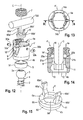
- shows a perspective exploded view of the polyaxial bone anchoring device with a spinal rod according to a second embodiment.
- Fig. 13
- shows a top view of the receiving part according to the second embodiment.
- Fig. 14
- shows a cross-sectional view of the receiving part along line B-B in
Fig. 13 . - Fig. 15
- shows a perspective view of the pressure element of the polyaxial bone anchoring device according to the second embodiment.
- Fig. 16
- shows a cross-sectional view of the pressure element in a first, unflexed configuration, wherein the section has been taken in a plane containing the central axis and extending through the middle of the resilient fingers of the pressure element.
- Fig. 17
- shows a cross-sectional view of the pressure element in a second, flexed configuration.
- Fig. 18a
- shows a cross-sectional view of the polyaxial bone anchoring device according to the second embodiment without an inserted rod, wherein the section has been taken along line B-B in
Fig. 13 with respect to the receiving part. - Fig. 18b
- shows an enlarged cross-sectional view of a portion of
Fig. 18a . - As shown in
Figs. 1 and 2 , a polyaxial bone anchoring device according to a first embodiment includes abone anchoring element 1 in the form of a bone screw having ashank 2 with a threaded portion and ahead 3. Thehead 3 typically has a spherically-shaped outer surface portion and arecess 3a at its free end for engagement with a driver or another tool. Thehead 3 may be held in a receivingpart 4 that couples thebone anchoring element 1 to astabilization rod 100. In the receivingpart 4, a sleeve-like insert piece 5 providing a seat for thehead 3 and apressure element 6 for exerting pressure onto thehead 3 are arranged. Furthermore, a fixation element in the form of, for example, afixation screw 7 is provided for securing and fixing therod 100 in the receivingpart 4. - Referring in particular to
Figs. 3 to 5 , the receivingpart 4 has atop end 4a and abottom end 4b, a central axis C and acoaxial bore 8 extending from thetop end 4a in the direction of thebottom end 4b. Adjacent to thetop end 4a, a substantiallyU-shaped recess 9 is provided that forms a channel for receiving therod 100. By means of therecess 9, two free legs are formed which are provided with aninternal thread 10 for cooperating with thefixation screw 7. - The
coaxial bore 8 opens into anaccommodation space 11 provided in a lower part of the receiving part, e.g. nearer to thebottom end 4b. Theaccommodation space 11 has alower opening 12 at thebottom end 4b of the receiving part. Theaccommodation space 11 further includes aseat portion 13 near thebottom end 4b of the receiving part in which the sleeve-like insert piece 5 may be seated. Theseat portion 13 has a spherical shape in order to provide a socket for a ball and socket joint that is formed by the sleeve-like insert piece 5 and the receivingpart 4. It should be noted that theseat portion 13 can also be tapered, or can have various other shapes that can be used to realize a ball and socket joint. An inner diameter of thelower opening 12 is smaller than an inner diameter of other portions of theaccommodation space 11. It shall also be noted that an inner diameter of thecoaxial bore 8 can vary such that thecoaxial bore 8 may have different portions with different diameters. - In order to allow the sleeve-
like insert piece 5 to be introduced from thetop end 4a, the receiving part has in the inner wall of the coaxial bore and theaccommodation space 11 tworecesses recesses U-shaped recess 9 and extend from a bottom of theU-shaped recess 9 into theaccommodation space 11. The size of therecesses top end 4a in a 90° tilted position, i.e. the width of therecesses like insert piece 5 in its axial direction. Therecesses accommodation space 11 to such an extent the tilting of the insert piece into theseat 13 is possible. - As can be seen in particular in
Figs. 1 and5 , the receivingpart 4 comprises a conically shapedcutout 15 that extends in circumferential direction and is provided in both legs of the receivingpart 4. Thecutout 15 is located at an axial position with respect to the central axis C that is between theaccommodation space 11 and theinternal thread 10. The orientation of theconical cutout 15 is such that thecutout 15 widens in a direction towards thebottom end 4b, thereby providing on each leg a conicallyinclined surface portion 15a, 15b including an angle of inclination α with the central axis C. The angle of inclination α may be, for example, approximately 25° (Fig. 11b ) or at least less than 70°. Abase surface 15c of the conical cutout may be oriented perpendicular to the central axis C. A maximum depth of thecutout 15 in a radial direction may be larger the inner diameter of thebore 8. Between the portion with theinternal thread 10 and theconical cutout 15 an undercutportion 16 may be provided with an internal diameter that is larger than the inner diameter of the upper edge of theconical cutout 15. - The sleeve-
like insert piece 5 is shown in particular inFigs. 1 and6 . The sleeve-insert piece 5 has anupper edge 5a and alower edge 5b. Between theupper edge 5a and thelower edge 5b, a sleeve-like insert piece 5 may have a spherically-shapedouter surface portion 51. A largest outer diameter of the sleeve-like insert piece is greater than the inner diameter of thelower opening 12 of the receivingpart 4. Hence, the sleeve-like insert piece 5 cannot escape through thelower opening 12 when it is seated in the receivingpart 4. The dimension or shape of the outerspherical surface portion 51 corresponds to that of the spherically-shapedseat portion 13 in the receivingpart 4 in such a way that the sleeve-like insert piece 5 can pivot and rotate in the receivingpart 4 when theinsert piece 5 is seated in theseat portion 13. When the sleeve-like insert piece 5 rests in theseat portion 13 in a coaxial configuration such that its center axis 5c is coaxial with the center axis C of the receivingpart 4, thelower edge 5b projects out of alower opening 12 as can be seen inFig. 11a . When the sleeve-like insert piece 5 is pivoted or angled in the receiving part, at least a portion of thelower edge 5b still projects out of thelower opening 12. - The sleeve-
insert piece 5 is hollow and has acentral portion 52 that is spherically-shaped with a radius corresponding to a radius of the spherically-shaped outer surface portion of thehead 3 of thebone anchoring element 1. A lower end of thecentral portion 52 forms ashoulder 53, an inner diameter of theshoulder 53 is smaller than a largest outer diameter of thespherical head 3, so that thehead 3 can rotate and pivot in the centralspherical portion 52 of the sleeve-like insert piece 5, similar to a ball and socket joint. Between theshoulder 53 and thelower edge 5b, a taperedportion 54 is provided that tapers outward to allow angulation of thebone anchoring element 1 until theshank 2 comes into contact with thelower edge 5b. Between the sphericalcentral portion 52 and theupper edge 5a, a taperedportion 55 is provided which also tapers outward. An inner diameter of taperedportion 55 and of a transition between the taperedportion 55 and the sphericalcentral portion 52 are greater than the largest outer diameter of thehead 3, so that thehead 3 can be inserted from theupper edge 5a. A height of the sleeve-like insert piece 5 in an axial direction is less than a height of thehead 3 in an axial direction, such that when thehead 3 is inserted into the sleeve-like insert piece 5, a portion of the spherical outer surface of thehead 3 still projects from theupper edge 5a of the sleeve-like insert piece 5. - Referring to
Figs. 7 and 8 , thepressure element 6 comprises a main body with a firstcylindrical portion 61 with a first outer diameter and a secondcylindrical portion 62 with a second outer diameter that is smaller than the first outer diameter. The firstcylindrical portion 61 defines anupper surface 6a and the secondcylindrical portion 62 defines alower edge 6b. Aspherical recess 63 is provided adjacent to thelower portion 6b. Therecess 63 is sized such that it matches the shape of the spherical portion of thehead 3. Furthermore, a coaxial throughhole 64 extends from theupper surface 6a into therecess 63 to allow the access with a tool to engage therecess 4 in thehead 3 of thebone anchoring element 1. In theupper surface 6a, a shallow substantially cylinder segment-shapedrecess 65 may be provided for guiding the rod. - The pressure element further comprises flexible sections in the form of two upstanding
resilient fingers upper surface 6a upwards. As shown in detail inFig. 9 , the outer wall of theresilient fingers top surface 6a substantially flush with the outer surface of the firstcylindrical portion 61. The inner surface of theresilient fingers upper surface 6a and substantially straight in a portion adjacent to the free end of the fingers. At their free ends, thefingers portion top surface inclined surface portion lower edge 6b. The angle of inclination of theinclined surface portion inclined surface portions 15a, 15b of the receiving part or can be substantially the same. The outwardly extendingportion surface inclined surface portion part 4. The dimensions of thepressure element 6 are such that the first outer diameter of the firstcylindrical portion 61 is only slightly smaller than the inner diameter of thecoaxial bore 8 so that the pressure element can slide along the inner wall of thecoaxial bore 8. - As can be seen in the cross-sectional view in
Fig. 9 , the thickness of theresilient fingers top surface top surface 6a of the firstcylindrical portion 61. Theresilient fingers Fig. 10 . - When the
head 3 with the sleeve-like insert piece 5 is inserted into the receiving part and seated in theseat portion 13 and thepressure element 6 is inserted, the height of theresilient fingers inclined surface portion inclined surface portion 15a, 15b of theconical cutout 15, respectively, as shown inFig. 11a . - The bone anchoring device, as a whole or in parts, is made of a bio-compatible material, such as a bio-compatible metal, for example titanium or stainless steel, a bio-compatible alloy such as Nitinol, or of bio-compatible plastic materials, such as for example, polyetheretherketone (PEEK). The parts may be of the same material or of different material.
- The polyaxial bone anchoring device may be pre-assembled. In the following, the steps of assembling the anchoring device are described. First, the sleeve-
like insert piece 5 may be introduced from thetop end 4a into the receivingpart 4 in such a manner that the sleeve-like insert piece is tilted by 90° and then introduced into the receiving part so that it extends intorecesses seat portion 13. Then the bone anchoring element may be inserted so that thehead 3 is seated in the sphericalcentral portion 52 of the sleeve-like insert piece 5. - Thereafter, the pressure element is inserted from the
top end 4a with an orientation such that the resilient fingers are arranged in the U-shaped recess. Then, the pressure element is rotated so that itsshallow recess 65 is aligned with theU-shaped recess 9 of the receiving part. Theresilient fingers conical cutout 15. When theinclined portions inclined surface portion 15a, 15b of thecutout 15, the fingers are slightly bent inward. Because in this configuration, theresilient fingers inclined surface portion Fig. 11a . By the elastic deformation of theresilient fingers pressure element 6 onto thehead 3 as depicted inFigs. 11a and 11b . Hence, a pre-load is applied to thehead 3 that holds thehead 3 with a low friction force. - Because the surface area of the
inclined surface portion 15a, 15b of theconical cutout 15 is greater than the surface area of theinclined surface portion inclined surface portion inclined surface portion 15a, 15b when the pressure element is moved downward. By means of this, the dimensional tolerances between the head, the sleeve-like insert piece and the pressure element can be balanced by appropriate positioning of thepressure element 6. Therefore, a reproducible, low friction force acting onto the head is generated. - The pressure element may additionally be secured against escaping through the
top end 4a. For example, the securing can be achieved by crimping (not shown). This may prevent that thepressure element 6 is pushed out through thetop end 4a because the elastic deformation of the fingers and the generated low friction force may not be sufficient to hold the pressure element in the receiving part in the pre-assembled state. - In use, the pre-assembled polyaxial bone anchoring device is inserted into a bone or a vertebra. Typically, at least two bone anchoring devices are used and connected with the
rod 100. The receiving parts are aligned by rotating and/or pivoting them with respect to the bone anchoring elements. The pre-load exerted onto the head can be overcome by manually rotating and/or pivoting the receiving part. Because of the low friction between the head and the pressure element, the anchoring device is convenient to handle. - Because the sleeve-
like insert piece 5 is rotatable and pivotable within the receivingpart 4, the polyaxial bone anchoring device has an enlarged range of angulation that can be achieved at any position within 360° of the receivingpart 4 with respect to thebone anchoring element 1. - When the receiving
part 4 is pivoted with respect to thebone anchoring element 1, theshank 2 of thebone anchoring element 1 comes into contact with thelower edge 5b of the sleeve-like insert piece, the sleeve-like insert piece 5 is also pivoted with thebone anchoring element 1. Theshank 2 may push theinsert piece 5 until theshank 2 abuts against the edge of thelower opening 12 of the receivingpart 4. The maximum pivot angle that can be achieved depends on the dimensions of the sleeve-like insert piece 5, the receivingpart 4 and thebone anchoring element 1, but is typically equal to or greater than 45° measured from a straight or zero angle position between the receivingpart 4 and thebone anchoring element 1. - After alignment of the receiving parts, the
rod 100 is inserted into the channel and then thefixation screw 7 is inserted and tightened. Thereby, the pressure element is moved downward slightly and presses thehead 3 into the seat and the sleeve-like insert piece into theseat portion 13. Theinner screw 7 is inserted and tightened and the pressure element and the rod are locked. - A polyaxial bone anchoring device according to a second embodiment will be described with reference to
Figs. 12 to 18b . Parts and portions which are the same or similar to those of the first embodiment are designated with the same reference numerals, and the descriptions thereof are not repeated. The bone anchoring device of the second embodiment differs from the bone anchoring device of the first embodiment by the construction of the receiving part and the pressure element. All other parts may be identical or similar to those of the first embodiment. - As shown in
Figs. 12 to 14 , the receiving part 4' has an undercut portion 16' but no conical cutout. At the lower end of the undercut portion 16' two opposedtransverse bores bores enlarged section pins head portion bores head portions enlarged portions Fig. 18a . When the pins are inserted, they may form a part of the receiving part. The free end of the pins that extends into the inside of the receiving part has aninclined surface portion inclined surface portions pins inclined surface portions bottom end 4b when the pins are inserted into the bores. The angle of inclination is approximately 50° or less measured with respect to the central axis C. The pins extend to such a length into the inside of the receiving part that the correspondinginclined surface portions inclined surface portions - The
pressure element 6' hasresilient fingers 66a', 66b' the outer surface of which is not flush with the outer surface of the firstcylindrical portion 61 but is offset from the outer surface of the first cylindrical portion. Hence, when thepressure element 6' is inserted into the receiving part, there is aspace 17 between the inner wall of thecoaxial bore 8 and the outside of theresilient fingers 66a', 66b'. Theinclined surface portions 69a', 69b' of the fingers are flat in this embodiment. - The
resilient fingers 66a', 66b' are flexible towards the central axis C as shown inFig. 17 . When thepressure element 6' is inserted into the receiving part 4' that has thepins bores inclined surface portions inclined surface portions pressure element 6' exerts a preload onto thehead 3 that holds thehead 3 in the sleeve-like insert piece and in theseat portion 13 with a low friction force. When thepressure element 6' is further pressed down onto the head during tightening of the fixation screw, theinclined surface portions inclined surface portions space 17 when it is no longer in contact with theinclined surface portion - Modifications of the embodiments described may also be made. For example, more than two resilient fingers may be present. In the second embodiment, more than two pins may be present according to the number of resilient fingers. In a further modification, only one single flexible section may be provided on the pressure element. The lower portion of the pressure element may be designed differently. The sleeve-like insert piece may be omitted. In this case, the accommodation space of the receiving part may be smaller and the head may be seated directly in the seat portion of the receiving part. The receiving part may be constructed so as to allow the insertion of the bone anchoring element from the bottom end. Also, the pressure element may be constructed so as to allow the insertion into the receiving part from the bottom end.
- Furthermore, the inclined surface portions need not to be conically-shaped as in the first embodiment or flat as in the second embodiment. they may have any shape which allows to generate a downward force.
- For the bone anchoring element, various different kinds of anchoring elements can be used and combined with the receiving part. These anchoring elements may be, for example, screws with different length, screws with different diameters, cannulated screws, screws with different thread forms, nails, hooks etc. For some anchoring elements, the head and the shaft may also be separate parts that are connectable to each other.
- Other kinds of locking devices including outer nuts, outer caps, bayonet locking devices, or others are also possible. Also, a two part locking device may be used with an outer locking device that acts onto the pressure element only and an inner locking device that presses onto the rod. The inner surface portion of the pressure element may have any other shape that is suitable to exert pressure onto the head.
- It shall also be noted that portions of the different described embodiments can also be combined with each other in various different combinations.
Claims (17)
- Polyaxial bone anchoring device including
a bone anchoring element (1) comprising a head (3) and a shank (2);
a receiving part (4, 4') for receiving a rod (100) for coupling the rod to the bone anchoring element, the receiving part comprising a first end (4a), an opposite second end (4b) and a central axis (C) extending through the first end and the second end, and
a channel (9) for receiving the rod and an accommodation space (11) for receiving the head;
a pressure element (6, 6') arranged in the receiving part and configured to exert pressure onto the head;
wherein the pressure element (6, 6') comprises at least one flexible section (66a, 66b; 66a', 66b'), characterized in that the at least one flexible section (66a, 66b; 66a', 66b') comprises an inclined surface portion (69a, 69b; 69a', 69b') with respect to the central axis (C) that cooperates with an inclined surface portion (15a, 15b; 32a, 32b) of the receiving part (4, 4') such as to hold the pressure element (6, 6') in a position in which it exerts a pre-load onto the head before the head is locked. - The polyaxial bone anchoring device of claim 1, wherein the at least one flexible section (66a, 66b; 66a', 66b') is formed by at least one upstanding resilient finger (66a, 66b; 66a', 66b').
- The polyaxial bone anchoring device of claim 1 or 2, wherein the at least one flexible section (66a, 66b; 66a', 66b') is configured to flex towards the central axis (C) of the receiving part.
- The polyaxial bone anchoring device of one of claims 1 to 3, wherein the inclined surface portion (69a, 69b; 69a', 69b') of the at least one flexible section (66a, 66b; 66a', 66b') of the pressure element and the corresponding inclined surface portion (15a, 15b; 32a, 32b) of the receiving part engage when the flexible section (66a, 66b; 66a', 66b') of the pressure element are in a flexed configuration.
- The polyaxial bone anchoring device of one of claims 1 to 4, wherein the inclined surface portion (69a, 69b; 69a', 69b') of the flexible section and the corresponding inclined surface portion (15a, 15b; 32a, 32b) of the (4, 4') receiving part remain in engagement when the pressure element (6, 6') is moved towards the head (3).
- The polyaxial bone anchoring device of one of claims 1 to 5, wherein an angle of inclination (α) of the inclined surface portion (15a, 15b; 32a, 32b) of the receiving part (4, 4') with respect to the central axis (C) is such that by engagement of the inclined surface portion (69a, 69b; 69a', 69b') of the flexible section of the pressure element and the inclined surface portion (15a, 15b; 32a, 32b) of the receiving part a force is generated onto the pressure element that is directed towards the head.
- The polyaxial bone anchoring device of one of claims 1 to 6, wherein an angle of inclination (α) of the inclined surface portion of the receiving part (15a, 15b; 32a, 32b) is approximately less than approximately 70°, preferably around 25°.
- The polyaxial bone anchoring device of one of claims 1 to 7, wherein an angle of inclination of the inclined surface portion (69a, 69b; 69a', 69b') of the flexible sections is smaller than or the same as an angle of inclination (α) of the inclined surface portion (15a, 15b; 32a, 32b) of the receiving part with respect to the central axis (C).
- The polyaxial bone anchoring device of one of claims 1 to 8, wherein two flexible sections (66a, 66b; 66a', 66b') are provided on the pressure element that are configured to enclose the rod (100) therebetween.
- The polyaxial bone anchoring device of one of claims 1 to 9, wherein the receiving part (4, 4') comprises a coaxial bore (8) for accommodating the pressure element (6, 6') and wherein the inclined surface portion (15a, 15b) of the receiving part (4) is provided by a conically-shaped recess (15) formed in the inner wall of the receiving part.
- The polyaxial bone anchoring device of one of claims 1 to 10, wherein the inclined surface portion (32a, 32b) of the receiving part is provided by pins (30a, 30b) extending through the wall of the receiving part (4').
- The polyaxial bone anchoring device of claim 11, wherein a surface (32a, 32b) of the pins (30a, 30b) that is oriented towards the central axis (C) is tapered.
- The polyaxial bone anchoring device of one of claims 1 to 12, wherein the pressure element (6, 6') is secured against escaping through the first end (4a) of the receiving part (4, 4'), preferably by a securing device.
- The polyaxial bone anchoring device of one of claims 1 to 13, wherein the head (3) is seated in a sleeve-like insert piece (5) that is accommodated in the accommodation space (11) and prevents the head from escaping through an opening (12) at the second end (4b) of the receiving part (4, 4').
- The polyaxial bone anchoring device of one of claims 1 to 14, wherein a locking device (7) is provided that is configured to directly or indirectly exert pressure onto the pressure element (6, 6') to lock the head with respect to the receiving part (4, 4').
- The polyaxial bone anchoring device of claim 14 or 15, wherein the sleeve like insert piece (5) is configured to rotate and pivot in the accommodation space (11).
- The polyaxial bone anchoring device of one of claims 1 to 16, wherein the flexible sections (66a, 66b; 66a', 66b') are located on a side of the pressure element that is opposite to the side that faces the head (3).
Priority Applications (14)
| Application Number | Priority Date | Filing Date | Title |
|---|---|---|---|
| ES12176959.0T ES2539388T3 (en) | 2012-07-18 | 2012-07-18 | Polyaxial bone anchoring device |
| EP20120176959 EP2687171B1 (en) | 2012-07-18 | 2012-07-18 | Polyaxial bone anchoring device |
| CN201310300711.6A CN103565504B (en) | 2012-07-18 | 2013-07-15 | Polyaxial bone anchoring device |
| TW102125132A TW201406340A (en) | 2012-07-18 | 2013-07-15 | Multi-axis bone fixation device |
| JP2013147396A JP6076216B2 (en) | 2012-07-18 | 2013-07-16 | Polyaxial bone anchoring device |
| KR1020130083840A KR20140011274A (en) | 2012-07-18 | 2013-07-16 | Polyaxial bone anchoring device |
| EP13176835.0A EP2687172B1 (en) | 2012-07-18 | 2013-07-17 | Polyaxial bone anchoring device |
| US13/944,328 US9241737B2 (en) | 2012-07-18 | 2013-07-17 | Polyaxial bone anchoring device |
| ES13176835.0T ES2536731T3 (en) | 2012-07-18 | 2013-07-17 | Polyaxial bone anchoring device |
| US14/987,504 US10076362B2 (en) | 2012-07-18 | 2016-01-04 | Polyaxial bone anchoring device |
| US16/113,277 US11129647B2 (en) | 2012-07-18 | 2018-08-27 | Polyaxial bone anchoring device |
| US17/412,013 US11963698B2 (en) | 2012-07-18 | 2021-08-25 | Polyaxial bone anchoring device |
| US18/631,974 US12599415B2 (en) | 2012-07-18 | 2024-04-10 | Polyaxial bone anchoring device |
| US19/556,328 US20260191566A1 (en) | 2012-07-18 | 2026-03-04 | Polyaxial bone anchoring device |
Applications Claiming Priority (1)
| Application Number | Priority Date | Filing Date | Title |
|---|---|---|---|
| EP20120176959 EP2687171B1 (en) | 2012-07-18 | 2012-07-18 | Polyaxial bone anchoring device |
Publications (2)
| Publication Number | Publication Date |
|---|---|
| EP2687171A1 true EP2687171A1 (en) | 2014-01-22 |
| EP2687171B1 EP2687171B1 (en) | 2015-04-22 |
Family
ID=46548287
Family Applications (2)
| Application Number | Title | Priority Date | Filing Date |
|---|---|---|---|
| EP20120176959 Active EP2687171B1 (en) | 2012-07-18 | 2012-07-18 | Polyaxial bone anchoring device |
| EP13176835.0A Active EP2687172B1 (en) | 2012-07-18 | 2013-07-17 | Polyaxial bone anchoring device |
Family Applications After (1)
| Application Number | Title | Priority Date | Filing Date |
|---|---|---|---|
| EP13176835.0A Active EP2687172B1 (en) | 2012-07-18 | 2013-07-17 | Polyaxial bone anchoring device |
Country Status (7)
| Country | Link |
|---|---|
| US (6) | US9241737B2 (en) |
| EP (2) | EP2687171B1 (en) |
| JP (1) | JP6076216B2 (en) |
| KR (1) | KR20140011274A (en) |
| CN (1) | CN103565504B (en) |
| ES (2) | ES2539388T3 (en) |
| TW (1) | TW201406340A (en) |
Cited By (5)
| Publication number | Priority date | Publication date | Assignee | Title |
|---|---|---|---|---|
| US10159519B2 (en) | 2014-08-11 | 2018-12-25 | Biedermann Technologies Gmbh & Co. Kg | Polyaxial bone anchoring device |
| US10675061B2 (en) | 2016-02-26 | 2020-06-09 | Medos International Sarl | Polyaxial bone fixation element |
| US11026730B2 (en) | 2017-05-10 | 2021-06-08 | Medos International Sarl | Bone anchors with drag features and related methods |
| US12171467B2 (en) | 2021-07-01 | 2024-12-24 | Biedermann Technologies Gmbh & Co. Kg | Bone anchoring device |
| US12310631B2 (en) | 2021-03-05 | 2025-05-27 | Medos International Sárl | Multi-feature polyaxial screw |
Families Citing this family (47)
| Publication number | Priority date | Publication date | Assignee | Title |
|---|---|---|---|---|
| US8814911B2 (en) | 2003-06-18 | 2014-08-26 | Roger P. Jackson | Polyaxial bone screw with cam connection and lock and release insert |
| US8444681B2 (en) | 2009-06-15 | 2013-05-21 | Roger P. Jackson | Polyaxial bone anchor with pop-on shank, friction fit retainer and winged insert |
| US9980753B2 (en) * | 2009-06-15 | 2018-05-29 | Roger P Jackson | pivotal anchor with snap-in-place insert having rotation blocking extensions |
| US8007522B2 (en) | 2008-02-04 | 2011-08-30 | Depuy Spine, Inc. | Methods for correction of spinal deformities |
| JP2012529969A (en) * | 2008-08-01 | 2012-11-29 | ロジャー・ピー・ジャクソン | Longitudinal connecting member with tensioning cord with sleeve |
| CN103917181A (en) | 2009-06-15 | 2014-07-09 | 罗杰.P.杰克逊 | Polyaxial Bone Anchor Including Sleeve Stem and Friction Fit Retainer with Low Profile Edge Lock |
| US11229457B2 (en) | 2009-06-15 | 2022-01-25 | Roger P. Jackson | Pivotal bone anchor assembly with insert tool deployment |
| US12383311B2 (en) | 2010-05-14 | 2025-08-12 | Roger P. Jackson | Pivotal bone anchor assembly and method for use thereof |
| WO2012128825A1 (en) * | 2011-03-24 | 2012-09-27 | Jackson Roger P | Polyaxial bone anchor with compound articulation and pop-on shank |
| US9993269B2 (en) * | 2011-07-15 | 2018-06-12 | Globus Medical, Inc. | Orthopedic fixation devices and methods of installation thereof |
| ES2418604T3 (en) * | 2011-08-18 | 2013-08-14 | Biedermann Technologies Gmbh & Co. Kg | Polyaxial bone anchoring device |
| US8911479B2 (en) | 2012-01-10 | 2014-12-16 | Roger P. Jackson | Multi-start closures for open implants |
| EP2674123B1 (en) | 2012-06-11 | 2018-03-21 | Biedermann Technologies GmbH & Co. KG | Polyaxial bone anchoring device |
| ES2539388T3 (en) | 2012-07-18 | 2015-06-30 | Biedermann Technologies Gmbh & Co. Kg | Polyaxial bone anchoring device |
| US9782204B2 (en) | 2012-09-28 | 2017-10-10 | Medos International Sarl | Bone anchor assemblies |
| US9775660B2 (en) | 2013-03-14 | 2017-10-03 | DePuy Synthes Products, Inc. | Bottom-loading bone anchor assemblies and methods |
| US9259247B2 (en) | 2013-03-14 | 2016-02-16 | Medos International Sarl | Locking compression members for use with bone anchor assemblies and methods |
| US10342582B2 (en) | 2013-03-14 | 2019-07-09 | DePuy Synthes Products, Inc. | Bone anchor assemblies and methods with improved locking |
| US9724145B2 (en) | 2013-03-14 | 2017-08-08 | Medos International Sarl | Bone anchor assemblies with multiple component bottom loading bone anchors |
| US20140277153A1 (en) | 2013-03-14 | 2014-09-18 | DePuy Synthes Products, LLC | Bone Anchor Assemblies and Methods With Improved Locking |
| US20140276895A1 (en) | 2013-03-15 | 2014-09-18 | Roger P. Jackson | Tower tool for minimally invasive surgery |
| US9498255B2 (en) * | 2013-12-31 | 2016-11-22 | Blackstone Medical, Inc. | Translational pedicle screw systems |
| US10064658B2 (en) | 2014-06-04 | 2018-09-04 | Roger P. Jackson | Polyaxial bone anchor with insert guides |
| US10543021B2 (en) | 2014-10-21 | 2020-01-28 | Roger P. Jackson | Pivotal bone anchor assembly having an open ring positioner for a retainer |
| US11219471B2 (en) * | 2014-10-21 | 2022-01-11 | Roger P. Jackson | Pivotal bone anchor receiver having an insert with post-placement tool deployment |
| EP3031415B1 (en) * | 2014-12-10 | 2018-10-31 | Biedermann Technologies GmbH & Co. KG | Coupling assembly and polyaxial bone anchoring device comprising the same |
| EP3158957B1 (en) | 2015-10-21 | 2020-02-12 | Biedermann Technologies GmbH & Co. KG | Coupling device for coupling a bone anchor to a rod and bone anchoring device with such a coupling device |
| EP3184063B1 (en) * | 2015-12-21 | 2019-07-10 | Biedermann Technologies GmbH & Co. KG | Polyaxial bone anchoring device |
| US10610265B1 (en) | 2017-07-31 | 2020-04-07 | K2M, Inc. | Polyaxial bone screw with increased angulation |
| US11311314B2 (en) | 2018-07-31 | 2022-04-26 | GetSet Surgical SA | Spinal surgery systems and methods |
| US11596449B2 (en) | 2018-09-13 | 2023-03-07 | Roger P. Jackson | Pivotal bone anchor assembly with modular receiver and universal shank head |
| US11234738B2 (en) | 2018-11-16 | 2022-02-01 | Roger P. Jackson | Pivotal bone anchor assembly having a deployable collet insert with internal pressure ring |
| USD926978S1 (en) | 2019-06-07 | 2021-08-03 | GetSet Surgical SA | Surgical instrument handle |
| USD896384S1 (en) | 2019-06-07 | 2020-09-15 | GetSet Surgical SA | Spinal fusion cage |
| USD927687S1 (en) | 2019-06-07 | 2021-08-10 | GetSet Surgical SA | Surgical instrument handle |
| USD926312S1 (en) | 2019-06-07 | 2021-07-27 | GetSet Surgical SA | Surgical instrument handle |
| EP3785649B1 (en) * | 2019-08-30 | 2022-08-03 | Biedermann Technologies GmbH & Co. KG | Bone anchoring device |
| WO2021061970A1 (en) * | 2019-09-24 | 2021-04-01 | Corelink, Llc | Polyaxial bone screw |
| WO2021127251A1 (en) | 2019-12-17 | 2021-06-24 | Jackson Roger P | Bone anchor assembly with closed ring retainer and internal snap ring |
| WO2022184797A1 (en) | 2021-03-05 | 2022-09-09 | Medos International Sarl | Selectively locking polyaxial screw |
| US11751915B2 (en) | 2021-07-09 | 2023-09-12 | Roger P. Jackson | Modular spinal fixation system with bottom-loaded universal shank heads |
| US12544113B2 (en) * | 2021-11-11 | 2026-02-10 | Orthofix Us Llc | Friction-fit implantable devices and assemblies |
| US12053209B2 (en) | 2022-01-18 | 2024-08-06 | Roger P. Jackson | Spinal fixation systems with modular receiver and ring retainer sub-assemblies for connecting with universal shank heads |
| US12414801B2 (en) | 2022-11-03 | 2025-09-16 | Roger P. Jackson | Spinal fixation system with modular receiver sub-assemblies for connecting with bi-spherical universal shank heads |
| US12471962B2 (en) | 2023-02-22 | 2025-11-18 | Nexxt Spine, LLC | Modular bone screw fixation system |
| US20250366891A1 (en) * | 2024-05-28 | 2025-12-04 | Orthofix Us Llc | Friction-fit modular polyaxial screw assemblies |
| EP4763111A1 (en) * | 2024-12-23 | 2026-06-24 | Biedermann Technologies GmbH & Co. KG | Coupling device for coupling a rod to a bone anchoring element |
Citations (2)
| Publication number | Priority date | Publication date | Assignee | Title |
|---|---|---|---|---|
| WO2009038697A1 (en) * | 2007-09-17 | 2009-03-26 | Jackson Roger P | Polyaxial bone anchor assembly with one-piece closure, pressure insert and plastic elongate member |
| EP2221012A1 (en) * | 2009-02-20 | 2010-08-25 | Biedermann Motech GmbH & Co. KG | Receiving part for receiving a rod for coupling the rod to a bone anchoring element and a bone anchoring device with such a receiving part |
Family Cites Families (103)
| Publication number | Priority date | Publication date | Assignee | Title |
|---|---|---|---|---|
| DE3669826D1 (en) | 1985-10-02 | 1990-05-03 | Ciba Geigy Ag | PROTECTION OF CROP PLANTS FROM PLANT- AND SEED-BASED PLANT DISEASES BY SEED TREATMENT WITH MICRO-ORGANISM CULTURES. |
| DE4425357C2 (en) | 1994-07-18 | 1996-07-04 | Harms Juergen | Anchoring element |
| DE19509332C1 (en) | 1995-03-15 | 1996-08-14 | Harms Juergen | Anchoring element |
| US5728098A (en) | 1996-11-07 | 1998-03-17 | Sdgi Holdings, Inc. | Multi-angle bone screw assembly using shape-memory technology |
| US6010503A (en) | 1998-04-03 | 2000-01-04 | Spinal Innovations, Llc | Locking mechanism |
| US6254602B1 (en) | 1999-05-28 | 2001-07-03 | Sdgi Holdings, Inc. | Advanced coupling device using shape-memory technology |
| DE19936286C2 (en) | 1999-08-02 | 2002-01-17 | Lutz Biedermann | bone screw |
| US6554834B1 (en) | 1999-10-07 | 2003-04-29 | Stryker Spine | Slotted head pedicle screw assembly |
| DE10157969C1 (en) | 2001-11-27 | 2003-02-06 | Biedermann Motech Gmbh | Element used in spinal and accident surgery comprises a shaft joined to a holding element having a U-shaped recess with two free arms having an internal thread with flanks lying at right angles to the central axis of the holding element |
| DE10157814B4 (en) | 2001-11-27 | 2004-12-02 | Biedermann Motech Gmbh | Closure device for securing a rod-shaped element in a holding element connected to a shaft |
| DE10164323C1 (en) * | 2001-12-28 | 2003-06-18 | Biedermann Motech Gmbh | Bone screw has holder element joined to shaft and possessing two free arms , with inner screw, slot, external nut, cavity and shoulder cooperating with attachment |
| US6837889B2 (en) | 2002-03-01 | 2005-01-04 | Endius Incorporated | Apparatus for connecting a longitudinal member to a bone portion |
| US7842073B2 (en) | 2002-04-18 | 2010-11-30 | Aesculap Ii, Inc. | Screw and rod fixation assembly and device |
| US6740086B2 (en) | 2002-04-18 | 2004-05-25 | Spinal Innovations, Llc | Screw and rod fixation assembly and device |
| US6829359B2 (en) | 2002-10-08 | 2004-12-07 | Arilg Electronics Co, Llc | Multispeaker sound imaging system |
| FR2847152B1 (en) | 2002-11-19 | 2005-02-18 | Eurosurgical | VERTEBRAL ANCHORING DEVICE AND ITS LOCKING DEVICE ON A POLY AXIAL SCREW |
| US6716214B1 (en) | 2003-06-18 | 2004-04-06 | Roger P. Jackson | Polyaxial bone screw with spline capture connection |
| US7377923B2 (en) | 2003-05-22 | 2008-05-27 | Alphatec Spine, Inc. | Variable angle spinal screw assembly |
| US7776067B2 (en) | 2005-05-27 | 2010-08-17 | Jackson Roger P | Polyaxial bone screw with shank articulation pressure insert and method |
| US7322981B2 (en) | 2003-08-28 | 2008-01-29 | Jackson Roger P | Polyaxial bone screw with split retainer ring |
| US8814911B2 (en) | 2003-06-18 | 2014-08-26 | Roger P. Jackson | Polyaxial bone screw with cam connection and lock and release insert |
| US7087057B2 (en) | 2003-06-27 | 2006-08-08 | Depuy Acromed, Inc. | Polyaxial bone screw |
| US7291151B2 (en) | 2003-07-25 | 2007-11-06 | Traiber, S.A. | Vertebral fixation device for the treatment of spondylolisthesis |
| AU2004266737B2 (en) | 2003-08-20 | 2010-05-13 | Warsaw Orthopedic, Inc. | Multi-axial orthopedic device and system, e.g. for spinal surgery |
| US7179261B2 (en) | 2003-12-16 | 2007-02-20 | Depuy Spine, Inc. | Percutaneous access devices and bone anchor assemblies |
| US8152810B2 (en) | 2004-11-23 | 2012-04-10 | Jackson Roger P | Spinal fixation tool set and method |
| EP1570794A1 (en) | 2004-03-04 | 2005-09-07 | U & I Corporation | Bone fixation apparatus, method and tool for assembling the same |
| US7503924B2 (en) | 2004-04-08 | 2009-03-17 | Globus Medical, Inc. | Polyaxial screw |
| US7857834B2 (en) * | 2004-06-14 | 2010-12-28 | Zimmer Spine, Inc. | Spinal implant fixation assembly |
| US8267969B2 (en) * | 2004-10-20 | 2012-09-18 | Exactech, Inc. | Screw systems and methods for use in stabilization of bone structures |
| US7604655B2 (en) | 2004-10-25 | 2009-10-20 | X-Spine Systems, Inc. | Bone fixation system and method for using the same |
| AU2005299617B2 (en) * | 2004-10-25 | 2010-10-28 | X-Spine Systems, Inc. | Pedicle screw systems and methods |
| US7691129B2 (en) | 2004-10-27 | 2010-04-06 | Felix Brent A | Spinal stabilizing system |
| US8308782B2 (en) * | 2004-11-23 | 2012-11-13 | Jackson Roger P | Bone anchors with longitudinal connecting member engaging inserts and closures for fixation and optional angulation |
| US9980753B2 (en) * | 2009-06-15 | 2018-05-29 | Roger P Jackson | pivotal anchor with snap-in-place insert having rotation blocking extensions |
| US7875065B2 (en) * | 2004-11-23 | 2011-01-25 | Jackson Roger P | Polyaxial bone screw with multi-part shank retainer and pressure insert |
| US7951172B2 (en) * | 2005-03-04 | 2011-05-31 | Depuy Spine Sarl | Constrained motion bone screw assembly |
| CA2605775C (en) | 2005-04-25 | 2013-08-13 | Synthes (U.S.A.) | Bone anchor with locking cap and method of spinal fixation |
| DE102005021879B4 (en) | 2005-05-04 | 2007-04-12 | Aesculap Ag & Co. Kg | Orthopedic anchoring element and osteosynthesis device |
| US8100947B2 (en) | 2005-05-25 | 2012-01-24 | K2M, Inc. | Low profile pedicle screw and rod assembly |
| EP1743584B1 (en) | 2005-07-12 | 2007-09-12 | BIEDERMANN MOTECH GmbH | Bone anchoring device |
| US7648565B2 (en) | 2005-07-13 | 2010-01-19 | Parker-Hannifin Corporation | Filter element |
| US8100916B2 (en) | 2005-07-21 | 2012-01-24 | Depuy Spine, Inc. | Instrument for inserting, adjusting and removing a surgical implant |
| US7909830B2 (en) | 2005-08-25 | 2011-03-22 | Synthes Usa, Llc | Methods of spinal fixation and instrumentation |
| US8100946B2 (en) | 2005-11-21 | 2012-01-24 | Synthes Usa, Llc | Polyaxial bone anchors with increased angulation |
| CN101500515A (en) | 2006-03-22 | 2009-08-05 | 先锋外科技术公司 | Low top bone fixation system and method for using the same |
| ES2318603T3 (en) | 2006-03-31 | 2009-05-01 | Biedermann Motech Gmbh | FIXING SYSTEM TO INSURE A ROD IN A RECEPTION PART INTENDED TO BE USED IN VERTEBRAL OR TRAUMATOLOGICAL SURGERY, BEAR ANCHORAGE DEVICE THAT INCLUDES SUCH ASSOCIATED FIXING AND TOOL SYSTEM. |
| ZA200808411B (en) | 2006-04-11 | 2009-12-30 | Synthes Gmbh | Minimally invasive fixation system |
| BRPI0621728A2 (en) | 2006-06-05 | 2012-10-16 | Traiber S L | vertebral fixation device and tool for mounting the same |
| US7922748B2 (en) * | 2006-06-16 | 2011-04-12 | Zimmer Spine, Inc. | Removable polyaxial housing for a pedicle screw |
| WO2008008511A2 (en) * | 2006-07-14 | 2008-01-17 | Laszlo Garamszegi | Pedicle screw assembly with inclined surface seat |
| WO2008022268A2 (en) | 2006-08-16 | 2008-02-21 | Pioneer Surgical Technology, Inc. | Spinal rod anchor device and method |
| BRPI0716665A2 (en) | 2006-08-17 | 2013-12-10 | Synthes Gmbh | DRIVER TO INSERT A BONE SCREW |
| US8016862B2 (en) | 2006-09-27 | 2011-09-13 | Innovasis, Inc. | Spinal stabilizing system |
| US8167910B2 (en) | 2006-10-16 | 2012-05-01 | Innovative Delta Technology Llc | Bone screw and associated assembly and methods of use thereof |
| US7699876B2 (en) | 2006-11-08 | 2010-04-20 | Ebi, Llc | Multi-axial bone fixation apparatus |
| ES2395948T3 (en) | 2006-12-22 | 2013-02-18 | Biedermann Technologies Gmbh & Co. Kg | Bone anchoring device |
| US20080200918A1 (en) | 2007-02-12 | 2008-08-21 | James Spitler | Pedicle screw driver |
| US8197517B1 (en) * | 2007-05-08 | 2012-06-12 | Theken Spine, Llc | Frictional polyaxial screw assembly |
| US7947065B2 (en) * | 2008-11-14 | 2011-05-24 | Ortho Innovations, Llc | Locking polyaxial ball and socket fastener |
| CA2692772A1 (en) | 2007-07-20 | 2009-01-29 | Synthes Usa, Llc | Polyaxial bone fixation element |
| US20100160980A1 (en) | 2007-07-26 | 2010-06-24 | Biotechni America Spine Group, Inc. | Spinal fixation assembly |
| DE102007042953B4 (en) | 2007-08-30 | 2015-01-22 | Aesculap Ag | Orthopedic retention system |
| DE102007042959B4 (en) | 2007-08-30 | 2011-03-31 | Aesculap Ag | Surgical retaining screw |
| US8398683B2 (en) * | 2007-10-23 | 2013-03-19 | Pioneer Surgical Technology, Inc. | Rod coupling assembly and methods for bone fixation |
| US8998958B2 (en) | 2007-12-20 | 2015-04-07 | Aesculap Implant Systems, Llc | Locking device introducer instrument |
| US9579126B2 (en) | 2008-02-02 | 2017-02-28 | Globus Medical, Inc. | Spinal rod link reducer |
| US8007522B2 (en) * | 2008-02-04 | 2011-08-30 | Depuy Spine, Inc. | Methods for correction of spinal deformities |
| WO2009124196A2 (en) * | 2008-04-03 | 2009-10-08 | Life Spine, Inc. | Top loading polyaxial spine screw assembly with one step lockup |
| EP2111811B1 (en) | 2008-04-22 | 2011-06-15 | BIEDERMANN MOTECH GmbH | Instrument for assembling a bone anchoring device |
| US8123785B2 (en) | 2008-05-08 | 2012-02-28 | Aesculap Implant Systems, Llc | Minimally invasive spinal stabilization system |
| JP2012529969A (en) | 2008-08-01 | 2012-11-29 | ロジャー・ピー・ジャクソン | Longitudinal connecting member with tensioning cord with sleeve |
| US9603629B2 (en) | 2008-09-09 | 2017-03-28 | Intelligent Implant Systems Llc | Polyaxial screw assembly |
| ES2392362T3 (en) * | 2008-10-08 | 2012-12-10 | Biedermann Technologies Gmbh & Co. Kg | Bone anchoring device and stabilization device for bone parts or vertebrae |
| US8506601B2 (en) * | 2008-10-14 | 2013-08-13 | Pioneer Surgical Technology, Inc. | Low profile dual locking fixation system and offset anchor member |
| JP2010099293A (en) * | 2008-10-24 | 2010-05-06 | Japan Medical Materials Corp | Bone anchor unit for vertebral column fixation and method for manufacturing the same |
| JP2012508038A (en) | 2008-11-03 | 2012-04-05 | ジンテス ゲゼルシャフト ミット ベシュレンクテル ハフツング | Single plane bone fixation assembly |
| US8246665B2 (en) | 2008-12-22 | 2012-08-21 | Life Spine, Inc. | Posterior cervical cross connector assemblies |
| US8241341B2 (en) * | 2009-03-20 | 2012-08-14 | Spinal Usa, Inc. | Pedicle screws and methods of using the same |
| US8998959B2 (en) | 2009-06-15 | 2015-04-07 | Roger P Jackson | Polyaxial bone anchors with pop-on shank, fully constrained friction fit retainer and lock and release insert |
| EP2727546A3 (en) | 2009-08-20 | 2014-07-30 | Biedermann Technologies GmbH & Co. KG | Bone anchoring device, tool and method for assembling the same and tool for use with the same |
| EP2485654B1 (en) * | 2009-10-05 | 2021-05-05 | Jackson P. Roger | Polyaxial bone anchor with non-pivotable retainer and pop-on shank, some with friction fit |
| CN102686174A (en) | 2009-11-18 | 2012-09-19 | 斯恩蒂斯有限公司 | Variable offset spine fixation system and method |
| WO2011069000A2 (en) | 2009-12-02 | 2011-06-09 | Spartek Medical, Inc. | Low profile spinal prosthesis incorporating a bone anchor having a deflectable post and a compound spinal rod |
| EP2679179B1 (en) * | 2009-12-21 | 2018-03-07 | Biedermann Technologies GmbH & Co. KG | Bone anchoring device |
| ES2394774T3 (en) * | 2010-05-05 | 2013-02-05 | Biedermann Technologies Gmbh & Co. Kg | Receiver piece intended to receive a bar for coupling with an anchoring element for bone, anchoring device for bone and method and tool for mounting it |
| US12383311B2 (en) * | 2010-05-14 | 2025-08-12 | Roger P. Jackson | Pivotal bone anchor assembly and method for use thereof |
| US8882817B2 (en) | 2010-08-20 | 2014-11-11 | K2M, Inc. | Spinal fixation system |
| US9393049B2 (en) | 2010-08-20 | 2016-07-19 | K2M, Inc. | Spinal fixation system |
| US8491641B2 (en) | 2010-09-28 | 2013-07-23 | Spinofix, Inc. | Pedicle screws and dynamic adaptors |
| EP2457527B1 (en) | 2010-11-24 | 2014-04-16 | Biedermann Technologies GmbH & Co. KG | Polyaxial bone anchoring device with enlarged pivot angle |
| JP2014507970A (en) | 2010-12-29 | 2014-04-03 | ロジャー・ピー・ジャクソン | A polyaxial bone anchor having an open flat retainer, pop-on shank, and friction fit insert |
| US9060812B2 (en) | 2011-03-29 | 2015-06-23 | Alphatec Spine, Inc. | Screw assembly with deformable bushing |
| US8888827B2 (en) | 2011-07-15 | 2014-11-18 | Globus Medical, Inc. | Orthopedic fixation devices and methods of installation thereof |
| EP2620112B1 (en) * | 2012-01-30 | 2014-11-12 | Biedermann Technologies GmbH & Co. KG | Bone anchoring device |
| JP2013208740A (en) * | 2012-03-30 | 2013-10-10 | Brother Industries Ltd | Ink cartridge |
| EP2674123B1 (en) | 2012-06-11 | 2018-03-21 | Biedermann Technologies GmbH & Co. KG | Polyaxial bone anchoring device |
| ES2539388T3 (en) | 2012-07-18 | 2015-06-30 | Biedermann Technologies Gmbh & Co. Kg | Polyaxial bone anchoring device |
| US9763702B2 (en) * | 2012-11-16 | 2017-09-19 | DePuy Synthes Products, Inc. | Bone fixation assembly |
| EP2764840B1 (en) * | 2013-02-11 | 2017-05-03 | Biedermann Technologies GmbH & Co. KG | Coupling assembly for coupling a rod to a bone anchoring element and bone anchoring device with such a coupling assembly |
| US8979898B2 (en) | 2013-02-20 | 2015-03-17 | K2M, Inc. | Iliosacral polyaxial screw |
| EP2829243B1 (en) | 2013-07-24 | 2016-11-02 | Biedermann Technologies GmbH & Co. KG | Coupling assembly for coupling a rod to a bone anchoring element, kit of such a coupling assembly different rod receiving elements and bone anchoring device |
| EP2985001B1 (en) | 2014-08-11 | 2017-04-19 | Biedermann Technologies GmbH & Co. KG | Polyaxial bone anchoring device |
-
2012
- 2012-07-18 ES ES12176959.0T patent/ES2539388T3/en active Active
- 2012-07-18 EP EP20120176959 patent/EP2687171B1/en active Active
-
2013
- 2013-07-15 TW TW102125132A patent/TW201406340A/en unknown
- 2013-07-15 CN CN201310300711.6A patent/CN103565504B/en not_active Expired - Fee Related
- 2013-07-16 JP JP2013147396A patent/JP6076216B2/en not_active Expired - Fee Related
- 2013-07-16 KR KR1020130083840A patent/KR20140011274A/en not_active Ceased
- 2013-07-17 ES ES13176835.0T patent/ES2536731T3/en active Active
- 2013-07-17 US US13/944,328 patent/US9241737B2/en active Active
- 2013-07-17 EP EP13176835.0A patent/EP2687172B1/en active Active
-
2016
- 2016-01-04 US US14/987,504 patent/US10076362B2/en active Active
-
2018
- 2018-08-27 US US16/113,277 patent/US11129647B2/en active Active
-
2021
- 2021-08-25 US US17/412,013 patent/US11963698B2/en active Active
-
2024
- 2024-04-10 US US18/631,974 patent/US12599415B2/en active Active
-
2026
- 2026-03-04 US US19/556,328 patent/US20260191566A1/en active Pending
Patent Citations (3)
| Publication number | Priority date | Publication date | Assignee | Title |
|---|---|---|---|---|
| WO2009038697A1 (en) * | 2007-09-17 | 2009-03-26 | Jackson Roger P | Polyaxial bone anchor assembly with one-piece closure, pressure insert and plastic elongate member |
| EP2221012A1 (en) * | 2009-02-20 | 2010-08-25 | Biedermann Motech GmbH & Co. KG | Receiving part for receiving a rod for coupling the rod to a bone anchoring element and a bone anchoring device with such a receiving part |
| US20100234902A1 (en) | 2009-02-20 | 2010-09-16 | Lutz Biedermann | Receiving part for receiving a rod for coupling the rod to a bone anchoring element and a bone anchoring device with such a receiving part |
Cited By (12)
| Publication number | Priority date | Publication date | Assignee | Title |
|---|---|---|---|---|
| US10159519B2 (en) | 2014-08-11 | 2018-12-25 | Biedermann Technologies Gmbh & Co. Kg | Polyaxial bone anchoring device |
| US10864030B2 (en) | 2014-08-11 | 2020-12-15 | Biedermann Technologies Gmbh & Co. Kg | Polyaxial bone anchoring device |
| US11576708B2 (en) | 2014-08-11 | 2023-02-14 | Biedermann Technologies Gmbh & Co. Kg | Polyaxial bone anchoring device |
| US12564431B2 (en) | 2014-08-11 | 2026-03-03 | Biedermann Technologies Gmbh & Co. Kg | Polyaxial bone anchoring device |
| US10675061B2 (en) | 2016-02-26 | 2020-06-09 | Medos International Sarl | Polyaxial bone fixation element |
| US11547449B2 (en) | 2016-02-26 | 2023-01-10 | Medos International Sarl | Polyaxial bone fixation element |
| US12396758B2 (en) | 2016-02-26 | 2025-08-26 | Medos International Sarl | Polyaxial bone fixation element |
| US11026730B2 (en) | 2017-05-10 | 2021-06-08 | Medos International Sarl | Bone anchors with drag features and related methods |
| US12310631B2 (en) | 2021-03-05 | 2025-05-27 | Medos International Sárl | Multi-feature polyaxial screw |
| US12364515B2 (en) | 2021-03-05 | 2025-07-22 | Medos International Sàrl | Multi-feature polyaxial screw |
| US12171467B2 (en) | 2021-07-01 | 2024-12-24 | Biedermann Technologies Gmbh & Co. Kg | Bone anchoring device |
| US12661154B2 (en) | 2021-07-01 | 2026-06-23 | Biedermann Technologies Gmbh & Co. Kg | Bone anchoring device |
Also Published As
| Publication number | Publication date |
|---|---|
| US20190053829A1 (en) | 2019-02-21 |
| US20260191566A1 (en) | 2026-07-09 |
| JP2014018664A (en) | 2014-02-03 |
| US12599415B2 (en) | 2026-04-14 |
| EP2687172A1 (en) | 2014-01-22 |
| US20220039838A1 (en) | 2022-02-10 |
| US20160192966A1 (en) | 2016-07-07 |
| CN103565504B (en) | 2017-07-28 |
| US11129647B2 (en) | 2021-09-28 |
| US9241737B2 (en) | 2016-01-26 |
| US10076362B2 (en) | 2018-09-18 |
| TW201406340A (en) | 2014-02-16 |
| JP6076216B2 (en) | 2017-02-08 |
| US20140025119A1 (en) | 2014-01-23 |
| KR20140011274A (en) | 2014-01-28 |
| EP2687171B1 (en) | 2015-04-22 |
| US11963698B2 (en) | 2024-04-23 |
| ES2539388T3 (en) | 2015-06-30 |
| US20240341818A1 (en) | 2024-10-17 |
| CN103565504A (en) | 2014-02-12 |
| EP2687172B1 (en) | 2015-03-11 |
| ES2536731T3 (en) | 2015-05-28 |
Similar Documents
| Publication | Publication Date | Title |
|---|---|---|
| EP2687171B1 (en) | Polyaxial bone anchoring device | |
| US20240277381A1 (en) | Polyaxial bone anchoring device with enlarged pivot angle | |
| EP2606841B1 (en) | Polyaxial bone anchoring device | |
| US9333011B2 (en) | Polyaxial bone anchoring device | |
| US20220133361A1 (en) | Polyaxial bone anchoring device | |
| EP2604204B1 (en) | Monoplanar bone anchoring device with selectable pivot plane | |
| EP2609883A1 (en) | A receiving part for receiving a rod for coupling the rod to a bone anchoring element | |
| EP2468198A1 (en) | Bone anchoring device | |
| EP2559390A1 (en) | Polyaxial bone anchoring device with enlarged pivot angle |
Legal Events
| Date | Code | Title | Description |
|---|---|---|---|
| PUAI | Public reference made under article 153(3) epc to a published international application that has entered the european phase |
Free format text: ORIGINAL CODE: 0009012 |
|
| AK | Designated contracting states |
Kind code of ref document: A1 Designated state(s): AL AT BE BG CH CY CZ DE DK EE ES FI FR GB GR HR HU IE IS IT LI LT LU LV MC MK MT NL NO PL PT RO RS SE SI SK SM TR |
|
| AX | Request for extension of the european patent |
Extension state: BA ME |
|
| 17P | Request for examination filed |
Effective date: 20140722 |
|
| RBV | Designated contracting states (corrected) |
Designated state(s): AL AT BE BG CH CY CZ DE DK EE ES FI FR GB GR HR HU IE IS IT LI LT LU LV MC MK MT NL NO PL PT RO RS SE SI SK SM TR |
|
| GRAP | Despatch of communication of intention to grant a patent |
Free format text: ORIGINAL CODE: EPIDOSNIGR1 |
|
| INTG | Intention to grant announced |
Effective date: 20141103 |
|
| GRAS | Grant fee paid |
Free format text: ORIGINAL CODE: EPIDOSNIGR3 |
|
| GRAA | (expected) grant |
Free format text: ORIGINAL CODE: 0009210 |
|
| AK | Designated contracting states |
Kind code of ref document: B1 Designated state(s): AL AT BE BG CH CY CZ DE DK EE ES FI FR GB GR HR HU IE IS IT LI LT LU LV MC MK MT NL NO PL PT RO RS SE SI SK SM TR |
|
| REG | Reference to a national code |
Ref country code: GB Ref legal event code: FG4D |
|
| REG | Reference to a national code |
Ref country code: CH Ref legal event code: EP |
|
| REG | Reference to a national code |
Ref country code: AT Ref legal event code: REF Ref document number: 722713 Country of ref document: AT Kind code of ref document: T Effective date: 20150515 Ref country code: CH Ref legal event code: NV Representative=s name: NOVAGRAAF INTERNATIONAL SA, CH |
|
| REG | Reference to a national code |
Ref country code: IE Ref legal event code: FG4D |
|
| REG | Reference to a national code |
Ref country code: DE Ref legal event code: R096 Ref document number: 602012006819 Country of ref document: DE Effective date: 20150603 |
|
| REG | Reference to a national code |
Ref country code: ES Ref legal event code: FG2A Ref document number: 2539388 Country of ref document: ES Kind code of ref document: T3 Effective date: 20150630 |
|
| REG | Reference to a national code |
Ref country code: NL Ref legal event code: VDEP Effective date: 20150422 |
|
| REG | Reference to a national code |
Ref country code: AT Ref legal event code: MK05 Ref document number: 722713 Country of ref document: AT Kind code of ref document: T Effective date: 20150422 |
|
| REG | Reference to a national code |
Ref country code: LT Ref legal event code: MG4D |
|
| PG25 | Lapsed in a contracting state [announced via postgrant information from national office to epo] |
Ref country code: NL Free format text: LAPSE BECAUSE OF FAILURE TO SUBMIT A TRANSLATION OF THE DESCRIPTION OR TO PAY THE FEE WITHIN THE PRESCRIBED TIME-LIMIT Effective date: 20150422 |
|
| PG25 | Lapsed in a contracting state [announced via postgrant information from national office to epo] |
Ref country code: HR Free format text: LAPSE BECAUSE OF FAILURE TO SUBMIT A TRANSLATION OF THE DESCRIPTION OR TO PAY THE FEE WITHIN THE PRESCRIBED TIME-LIMIT Effective date: 20150422 Ref country code: FI Free format text: LAPSE BECAUSE OF FAILURE TO SUBMIT A TRANSLATION OF THE DESCRIPTION OR TO PAY THE FEE WITHIN THE PRESCRIBED TIME-LIMIT Effective date: 20150422 Ref country code: NO Free format text: LAPSE BECAUSE OF FAILURE TO SUBMIT A TRANSLATION OF THE DESCRIPTION OR TO PAY THE FEE WITHIN THE PRESCRIBED TIME-LIMIT Effective date: 20150722 Ref country code: LT Free format text: LAPSE BECAUSE OF FAILURE TO SUBMIT A TRANSLATION OF THE DESCRIPTION OR TO PAY THE FEE WITHIN THE PRESCRIBED TIME-LIMIT Effective date: 20150422 Ref country code: PT Free format text: LAPSE BECAUSE OF FAILURE TO SUBMIT A TRANSLATION OF THE DESCRIPTION OR TO PAY THE FEE WITHIN THE PRESCRIBED TIME-LIMIT Effective date: 20150824 |
|
| PG25 | Lapsed in a contracting state [announced via postgrant information from national office to epo] |
Ref country code: AT Free format text: LAPSE BECAUSE OF FAILURE TO SUBMIT A TRANSLATION OF THE DESCRIPTION OR TO PAY THE FEE WITHIN THE PRESCRIBED TIME-LIMIT Effective date: 20150422 Ref country code: GR Free format text: LAPSE BECAUSE OF FAILURE TO SUBMIT A TRANSLATION OF THE DESCRIPTION OR TO PAY THE FEE WITHIN THE PRESCRIBED TIME-LIMIT Effective date: 20150723 Ref country code: RS Free format text: LAPSE BECAUSE OF FAILURE TO SUBMIT A TRANSLATION OF THE DESCRIPTION OR TO PAY THE FEE WITHIN THE PRESCRIBED TIME-LIMIT Effective date: 20150422 Ref country code: IS Free format text: LAPSE BECAUSE OF FAILURE TO SUBMIT A TRANSLATION OF THE DESCRIPTION OR TO PAY THE FEE WITHIN THE PRESCRIBED TIME-LIMIT Effective date: 20150822 Ref country code: LV Free format text: LAPSE BECAUSE OF FAILURE TO SUBMIT A TRANSLATION OF THE DESCRIPTION OR TO PAY THE FEE WITHIN THE PRESCRIBED TIME-LIMIT Effective date: 20150422 |
|
| REG | Reference to a national code |
Ref country code: DE Ref legal event code: R097 Ref document number: 602012006819 Country of ref document: DE |
|
| PG25 | Lapsed in a contracting state [announced via postgrant information from national office to epo] |
Ref country code: EE Free format text: LAPSE BECAUSE OF FAILURE TO SUBMIT A TRANSLATION OF THE DESCRIPTION OR TO PAY THE FEE WITHIN THE PRESCRIBED TIME-LIMIT Effective date: 20150422 Ref country code: DK Free format text: LAPSE BECAUSE OF FAILURE TO SUBMIT A TRANSLATION OF THE DESCRIPTION OR TO PAY THE FEE WITHIN THE PRESCRIBED TIME-LIMIT Effective date: 20150422 |
|
| PLBE | No opposition filed within time limit |
Free format text: ORIGINAL CODE: 0009261 |
|
| STAA | Information on the status of an ep patent application or granted ep patent |
Free format text: STATUS: NO OPPOSITION FILED WITHIN TIME LIMIT |
|
| PG25 | Lapsed in a contracting state [announced via postgrant information from national office to epo] |
Ref country code: SK Free format text: LAPSE BECAUSE OF FAILURE TO SUBMIT A TRANSLATION OF THE DESCRIPTION OR TO PAY THE FEE WITHIN THE PRESCRIBED TIME-LIMIT Effective date: 20150422 Ref country code: MC Free format text: LAPSE BECAUSE OF FAILURE TO SUBMIT A TRANSLATION OF THE DESCRIPTION OR TO PAY THE FEE WITHIN THE PRESCRIBED TIME-LIMIT Effective date: 20150422 Ref country code: RO Free format text: LAPSE BECAUSE OF NON-PAYMENT OF DUE FEES Effective date: 20150422 Ref country code: PL Free format text: LAPSE BECAUSE OF FAILURE TO SUBMIT A TRANSLATION OF THE DESCRIPTION OR TO PAY THE FEE WITHIN THE PRESCRIBED TIME-LIMIT Effective date: 20150422 Ref country code: CZ Free format text: LAPSE BECAUSE OF FAILURE TO SUBMIT A TRANSLATION OF THE DESCRIPTION OR TO PAY THE FEE WITHIN THE PRESCRIBED TIME-LIMIT Effective date: 20150422 |
|
| 26N | No opposition filed |
Effective date: 20160125 |
|
| PG25 | Lapsed in a contracting state [announced via postgrant information from national office to epo] |
Ref country code: LU Free format text: LAPSE BECAUSE OF FAILURE TO SUBMIT A TRANSLATION OF THE DESCRIPTION OR TO PAY THE FEE WITHIN THE PRESCRIBED TIME-LIMIT Effective date: 20150718 |
|
| REG | Reference to a national code |
Ref country code: IE Ref legal event code: MM4A |
|
| PG25 | Lapsed in a contracting state [announced via postgrant information from national office to epo] |
Ref country code: SI Free format text: LAPSE BECAUSE OF FAILURE TO SUBMIT A TRANSLATION OF THE DESCRIPTION OR TO PAY THE FEE WITHIN THE PRESCRIBED TIME-LIMIT Effective date: 20150422 |
|
| REG | Reference to a national code |
Ref country code: FR Ref legal event code: PLFP Year of fee payment: 5 |
|
| PG25 | Lapsed in a contracting state [announced via postgrant information from national office to epo] |
Ref country code: IE Free format text: LAPSE BECAUSE OF NON-PAYMENT OF DUE FEES Effective date: 20150718 |
|
| PG25 | Lapsed in a contracting state [announced via postgrant information from national office to epo] |
Ref country code: BE Free format text: LAPSE BECAUSE OF FAILURE TO SUBMIT A TRANSLATION OF THE DESCRIPTION OR TO PAY THE FEE WITHIN THE PRESCRIBED TIME-LIMIT Effective date: 20150422 |
|
| PGFP | Annual fee paid to national office [announced via postgrant information from national office to epo] |
Ref country code: IT Payment date: 20160728 Year of fee payment: 5 |
|
| PGFP | Annual fee paid to national office [announced via postgrant information from national office to epo] |
Ref country code: FR Payment date: 20160722 Year of fee payment: 5 |
|
| PGFP | Annual fee paid to national office [announced via postgrant information from national office to epo] |
Ref country code: ES Payment date: 20160722 Year of fee payment: 5 |
|
| PG25 | Lapsed in a contracting state [announced via postgrant information from national office to epo] |
Ref country code: MT Free format text: LAPSE BECAUSE OF FAILURE TO SUBMIT A TRANSLATION OF THE DESCRIPTION OR TO PAY THE FEE WITHIN THE PRESCRIBED TIME-LIMIT Effective date: 20150422 |
|
| PG25 | Lapsed in a contracting state [announced via postgrant information from national office to epo] |
Ref country code: HU Free format text: LAPSE BECAUSE OF FAILURE TO SUBMIT A TRANSLATION OF THE DESCRIPTION OR TO PAY THE FEE WITHIN THE PRESCRIBED TIME-LIMIT; INVALID AB INITIO Effective date: 20120718 Ref country code: SM Free format text: LAPSE BECAUSE OF FAILURE TO SUBMIT A TRANSLATION OF THE DESCRIPTION OR TO PAY THE FEE WITHIN THE PRESCRIBED TIME-LIMIT Effective date: 20150422 Ref country code: BG Free format text: LAPSE BECAUSE OF FAILURE TO SUBMIT A TRANSLATION OF THE DESCRIPTION OR TO PAY THE FEE WITHIN THE PRESCRIBED TIME-LIMIT Effective date: 20150422 |
|
| PG25 | Lapsed in a contracting state [announced via postgrant information from national office to epo] |
Ref country code: SE Free format text: LAPSE BECAUSE OF FAILURE TO SUBMIT A TRANSLATION OF THE DESCRIPTION OR TO PAY THE FEE WITHIN THE PRESCRIBED TIME-LIMIT Effective date: 20150422 Ref country code: CY Free format text: LAPSE BECAUSE OF FAILURE TO SUBMIT A TRANSLATION OF THE DESCRIPTION OR TO PAY THE FEE WITHIN THE PRESCRIBED TIME-LIMIT Effective date: 20150422 |
|
| REG | Reference to a national code |
Ref country code: FR Ref legal event code: ST Effective date: 20180330 |
|
| PG25 | Lapsed in a contracting state [announced via postgrant information from national office to epo] |
Ref country code: FR Free format text: LAPSE BECAUSE OF NON-PAYMENT OF DUE FEES Effective date: 20170731 |
|
| PG25 | Lapsed in a contracting state [announced via postgrant information from national office to epo] |
Ref country code: TR Free format text: LAPSE BECAUSE OF FAILURE TO SUBMIT A TRANSLATION OF THE DESCRIPTION OR TO PAY THE FEE WITHIN THE PRESCRIBED TIME-LIMIT Effective date: 20150422 Ref country code: MK Free format text: LAPSE BECAUSE OF FAILURE TO SUBMIT A TRANSLATION OF THE DESCRIPTION OR TO PAY THE FEE WITHIN THE PRESCRIBED TIME-LIMIT Effective date: 20150422 |
|
| PG25 | Lapsed in a contracting state [announced via postgrant information from national office to epo] |
Ref country code: IT Free format text: LAPSE BECAUSE OF NON-PAYMENT OF DUE FEES Effective date: 20170718 |
|
| REG | Reference to a national code |
Ref country code: ES Ref legal event code: FD2A Effective date: 20181025 |
|
| PG25 | Lapsed in a contracting state [announced via postgrant information from national office to epo] |
Ref country code: AL Free format text: LAPSE BECAUSE OF FAILURE TO SUBMIT A TRANSLATION OF THE DESCRIPTION OR TO PAY THE FEE WITHIN THE PRESCRIBED TIME-LIMIT Effective date: 20150422 |
|
| PG25 | Lapsed in a contracting state [announced via postgrant information from national office to epo] |
Ref country code: ES Free format text: LAPSE BECAUSE OF NON-PAYMENT OF DUE FEES Effective date: 20170719 |
|
| P01 | Opt-out of the competence of the unified patent court (upc) registered |
Effective date: 20230525 |
|
| PGFP | Annual fee paid to national office [announced via postgrant information from national office to epo] |
Ref country code: DE Payment date: 20250729 Year of fee payment: 14 |
|
| PGFP | Annual fee paid to national office [announced via postgrant information from national office to epo] |
Ref country code: GB Payment date: 20250701 Year of fee payment: 14 |
|
| PGFP | Annual fee paid to national office [announced via postgrant information from national office to epo] |
Ref country code: CH Payment date: 20250801 Year of fee payment: 14 |
|
| REG | Reference to a national code |
Ref country code: CH Ref legal event code: U11 Free format text: ST27 STATUS EVENT CODE: U-0-0-U10-U11 (AS PROVIDED BY THE NATIONAL OFFICE) Effective date: 20260801 |