EP2685786B1 - Lighting device - Google Patents
Lighting device Download PDFInfo
- Publication number
- EP2685786B1 EP2685786B1 EP13173318.0A EP13173318A EP2685786B1 EP 2685786 B1 EP2685786 B1 EP 2685786B1 EP 13173318 A EP13173318 A EP 13173318A EP 2685786 B1 EP2685786 B1 EP 2685786B1
- Authority
- EP
- European Patent Office
- Prior art keywords
- unit
- light
- output
- wavelength band
- lighting device
- Prior art date
- Legal status (The legal status is an assumption and is not a legal conclusion. Google has not performed a legal analysis and makes no representation as to the accuracy of the status listed.)
- Active
Links
Images



Classifications
-
- H—ELECTRICITY
- H05—ELECTRIC TECHNIQUES NOT OTHERWISE PROVIDED FOR
- H05B—ELECTRIC HEATING; ELECTRIC LIGHT SOURCES NOT OTHERWISE PROVIDED FOR; CIRCUIT ARRANGEMENTS FOR ELECTRIC LIGHT SOURCES, IN GENERAL
- H05B45/00—Circuit arrangements for operating light-emitting diodes [LED]
- H05B45/20—Controlling the colour of the light
- H05B45/24—Controlling the colour of the light using electrical feedback from LEDs or from LED modules
Definitions
- the present invention relates to a lighting device.
- Japanese Utility Model No. 3159820 describes an example of a lighting device including a main power supply and a backup power supply. When the supply of power from the main power supply to a light source is interrupted, the light source is supplied with power from the backup power supply.
- the lighting device of Japanese Utility Model No. 3159820 further includes a main light source and a backup light source.
- the backup light source is formed by an LED.
- the low power consumption backup (LED) light source is used so that the backup power supply, which is a rechargeable battery (battery cell), may be used for a relatively long time.
- a white LED (20) is for emitting illumination light entirely to exterior, and comprises a first LED element (4) and a second LED element (5) which have mutually different emission wavelengths, and a sealing member (10) including a fluorescent material (8) which is excited to emit yellow light (sy) and for sealing at least the first LED element, the first LED element (4) being a long wave length-blue LED element for emitting blue light (sb1) of a long wave length in which a peak wave length is in the range of 470 nm to 490 nm, the second LED element being a red LED element for emitting red light (sr).
- US 2010/264432 A1 shows a light emitting device that comprises two light-emitting diode (LED) groups, a group of luminophor layers, and an input terminal.
- the first LED group includes at least one blue LED emitting light having a dominant wavelength in a range between 400 nm and 480 nm
- the second LED group includes at least one red-orange LED emitting light having a dominant wavelength in a range between 610 nm and 630 nm.
- the group of luminophor layers which are selected from one of silicates, nitrides, and nitrogen oxides, are positioned above the first LED group and partially converts the light emitted by the first LED group into light having a dominant wavelength in a range between 500 nm and 555 nm.
- the input terminal is connected to the two LED groups for providing desired electric energy thereto.
- US 2011/0084616 A1 relates to a solid state lighting apparatus which includes a plurality of light emitting diodes, a sensor configured to output a sensor signal indicative of at least one operating condition of the solid state lighting apparatus, and a control circuit coupled to the sensor.
- the control circuit is configured to temporarily interrupt electrical current to ones of the plurality of light emitting diodes at respective intervals responsive to the sensor signal indicating that the operating condition does not meet a desired operating threshold to provide a visible indicator thereof in light emitted by the apparatus.
- EP 1 160 883 A2 shows an LED lamp which includes blue and red LEDs and a phosphor.
- the blue LED produces an emission at a wavelength falling within a blue wavelength range.
- the red LED produces an emission at a wavelength falling within a red wavelength range.
- the phosphor is photoexcited by the emission of the blue LED to exhibit a luminescence having an emission spectrum in an intermediate wavelength range between the blue and red wavelength ranges.
- Japanese Laid-Open Patent Publication No. 2005-11812 discloses a lighting device that uses three LED light sources having different wavelengths and executes spectral control to generate light in accordance with a mesopic vision environment. Further, the lighting device of Japanese Laid-Open Patent Publication No. 2005-11812 uses LED light sources, and thus, consumes less power than fluorescent lamps and incandescent light bulbs.
- Such a lighting device uses three types of LED light sources having different wavelengths to improve visibility under a mesopic vision environment.
- the LED light sources increase the number of components.
- a lighting device 10 according to one embodiment of the present invention will now be described with reference to the drawings.
- the lighting device 10 of the present embodiment includes an illumination unit 11 and an activation circuit 12.
- the illumination unit 11 externally emits light, and the activation circuit 12 controls the activation of the illumination unit 11.
- the illumination unit 11 includes two LED light sources 21 and 22 and a fluorescent body 23.
- the LED light sources 21 and 22 emit different types of blue light.
- the fluorescent body 23 covers a light emitting surface of the LED light source 22. Further, the fluorescent body 23 emits yellow light when excited upon absorption of light from the LED light source 22.
- the LED light source 21 emits a short wavelength light
- the fluorescent body 23 and the LED light source 22 emit a long wavelength light.
- the activation circuit 12 of the lighting device 10 includes a main activation circuit unit 31, a backup activation circuit unit 32, a switch circuit unit 33, an activation detection unit 34, a charge unit 35, a power unit 36, a switch 37, an output varying unit 38, and a time control unit 39.
- the main activation circuit unit 31 is electrically connected to an AC power supply D.
- the switch circuit unit 33 electrically connects the main activation circuit unit 31 to the two LED light sources 21 and 22 of the illumination unit 11.
- the two LED light sources 21 and 22 are supplied with power from the AC power supply D through the main activation circuit unit 31 and the switch circuit unit 33. This allows for activation of the two LED light sources 21 and 22.
- the main activation circuit unit 31 and the AC power supply D form a main power supply unit.
- the backup activation circuit unit 32 is electrically connected to the charge unit 35.
- the output varying unit 38 and the switch circuit unit 33 connect the backup activation circuit unit 32 to the LED light source 21 of the illumination unit 11.
- the charge unit 35 is electrically connected to the power unit 36.
- the switch 37 which may be turned on and off, electrically connects the power unit 36 to the AC power supply D. When the switch 37 is turned on, the charge unit 35 accumulates power supplied from the AC power supply D through the power unit 36.
- the LED light source 22 is supplied with power from the charge unit 35 through the backup activation circuit unit 32. This allows for activation of the LED light source 22.
- the backup activation circuit unit 32 and the charge unit 35 form a backup power supply unit.
- the activation detection unit 34 detects whether or not power is supplied from the AC power supply D to the main activation circuit unit 31. When the activation detection unit 34 determines that the LED light source 21 is not activated (deactivated) the activation detection unit 34 provides the output varying unit 38 with a varying signal. Upon receipt of the varying signal, the output varying unit 38 controls the switch circuit unit 33 to switch to a power line extending through the backup activation circuit unit 32. More specifically, upon receipt of the varying signal, the output varying unit 38 functions to supply the power from the backup activation circuit unit 32 to the LED light source 21 through the output varying unit 38 and the switch circuit unit 33.
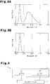
- the main activation circuit unit 31 controls the activation of the two LED light sources 21 and 22. For example, when an activation operation is performed with an operation switch (not shown), the LED light sources 21 and 22 are activated, and the illumination unit 11 emits white light (refer to Fig. 3A ). When the switch 37 is ON, power from the AC power supply D is accumulated in the charge unit 35 through the power unit 36.
- the activation detection unit 34 When the supply of power from the AC power supply D is interrupted (abnormal situation) by a wire breakage or the like, the activation detection unit 34 provides the output varying unit 38 with a varying signal. Upon receipt of the varying signal, the output varying unit 38 controls the switch circuit unit 33 to switch to the power line extending through the backup activation circuit unit 32. Thus, the backup activation circuit unit 32 is supplied with power from the charge unit 35 instead of the AC power supply D. Then, for example, when an activation operation is performed with an operation switch (not shown), the LED light source 21 is activated, and the illumination unit 11 emits blue light (refer to Fig. 3B ). In this case, the LED light source 22 covered by the yellow fluorescent body 23 is deactivated. This decreases the long wavelength band light output from the LED light source 22 to zero.
- the human retina has photoreceptor cells including rods, which function under a mesopic vision situation or a scotopic vision situation.
- the activation of the LED light source 21 that emits short wavelength band light e.g., blue light
- the lighting device 10 of the present embodiment has the advantages described below.
- the output varying unit 38 may be configured to gradually decrease the long wavelength band light. This allows for gradual shifting to only the short wavelength band light, and allows for reduction in the time used chromatic adaptation. Thus, a person would not feel discomfort with such a configuration.
- the activation circuit 12 includes the time control unit 39 electrically connected to the output varying unit 38.
- the time control unit 39 measures the elapsed time from when the output varying unit 38 receives the varying signal.
- the output varying unit 38 controls the switching of the switch circuit unit 33 after the predetermined time elapses based on the measured elapsed time.
- the illumination unit 11 includes the two LED light sources 21 and 22 of substantially the same color (same wavelength band), and the LED light source 22 is covered by the fluorescent body 23 to emit white light.
- an LED light source 41 that emits blue light and an LED light source 42 that emits light in the long wavelength band such as orange color may be used to emit white light by combining long wavelength band light, such as the blue light and the orange light.
- the two LED light sources 21 and 22 are activated during a normal operation.
- the illumination unit 11 may include an LED light source 43 that emits white light and an LED light source 44 that emits blue light.
- the LED light source 43 may be activated to emit white light.
- the LED light source 44 may be activated to emit blue light.
- the illumination unit 11 may include an LED light source 45 that emits blue light and a fluorescent body 46 that emits blue light and a fluorescent body 46 that emits yellow (orange) light when excited by the light of the LED light source 45. Further, the illumination unit 11 includes an output varying unit 47 that decreases the output of long wavelength band light by cutting or moving the fluorescent body 46 during a backup operation. In this configuration, under a backup operation, the light (blue light) may be emitted from only the LED light source 45. Further, the number of LED light sources 45 may be reduced.
- the illumination unit 11 may include an LED light source 51 that emits white light, a liquid crystal filter 52 arranged opposing an emission surface of the LED light source 51, and a liquid crystal control unit 53 that controls the liquid crystal filter 52. This allows the liquid crystal control unit 53 to control the liquid crystal filter 52 and emit light having a short wavelength during a backup situation.
- the illumination unit 11 may include a light flux measurement unit 56 that measures the light flux of the two LED light sources 21 and 22.
- the output varying unit 38 decreases the output of the long wavelength band light.
- Fig. 8 does not show the backup activation circuit unit 32 and the charge unit 35 that are used during a backup operation.
- the LED light source 22 emits long wavelength band light
- the fluorescent body 23 and the LED light source 21 emit short wavelength band light
- the illumination unit 11 may include a short wavelength light source unit and a long wavelength light source unit that emits, to the short wavelength light source, short wavelength band light having a relatively small output (spectral intensity) and long wavelength band light having a relatively large output.
- the short wavelength light source unit includes, for example, an LED light source and a fluorescent body excited by the light of the LED light source.
- the short wavelength light source unit includes, for example, a first peak wavelength P1 in the proximity of approximately 450 nm and a second peak wavelength P2 in the proximity of approximately 550 nm.
- the short wavelength LED light source is configured so that the light output at the second peak wavelength P2 is approximately 0.3.
- the short wavelength light source unit is configured so that the correlated color temperature is 10000 K, the average color rendering index Ra is 73, and the S/P ratio is 2.28.
- the S/P ratio is the ratio of scotopic vision brightness Ls, which is calculated by integrating the spectral luminous efficiency V' ( ⁇ ) under scotopic vision and the spectral characteristics of a lamp, and the photopic vision brightness Lp, which is calculated by the spectral luminous efficiency V ( ⁇ ) under photopic vision and the spectral characteristics of a lamp.
- the long wavelength light source unit includes, for example, an LED light source and a fluorescent body excited by the light of the LED light source.
- the long wavelength light source unit emits light of a short wavelength band having a relatively small light output and light of a long wavelength band having a relatively large light output to the short wavelength light source unit.
- the long wavelength light source unit emits light including spectrum A, shown by the solid line in Fig. 10 , and spectrum B, shown by the broken line in Fig. 10 .
- the spectrum A of the long wavelength light source unit has a first peak wavelength P1 in the proximity of approximately 455 nm, a second peak wavelength P2 in the proximity of approximately 490 nm, and a third peak wavelength P3 in the proximity of approximately 600 nm.
- the long wavelength light source unit that emits the spectrum A is configured so that the light output at the second peak wavelength P2 is approximately 0.9 and the light output at the third peak wavelength P3 is approximately 0.53. Further, the long wavelength light source unit that emits the spectrum A is configured so that the correlated color temperature is 6800 K, the average color rendering index Ra is 85, and the S/P ratio is 2.79.
- spectrum X shown by the solid line indicates the spectrum of synthesized light when activating the short wavelength light source unit and the long wavelength light source emitting the spectrum A.
- the synthesized light has a correlated color temperature of 8000 K, an average color rendering index Ra of 95, and an S/P ratio of 2.62.
- the long wavelength light source unit that emits the spectrum B shown by the broken line in Fig. 10 , has a first peak wavelength P1 in the proximity of approximately 440 nm and a second peak wavelength P2 in the proximity of approximately 550 nm.
- the long wavelength light source unit that emits the spectrum B is configured so that the light output at the second peak wavelength P2 is approximately 0.43.
- the long wavelength light source unit that emits the spectrum B is configured so that the correlated color temperature is 7100 K, the average color rendering index Ra is 70, and the S/P ratio is 2.04.
- spectrum Y shown by the broken line indicates the spectrum of synthesized light when activating the short wavelength light source unit and the long wavelength light source emitting the spectrum B.
- the synthesized light has a correlated color temperature of 8100 K, an average color rendering index Ra of 71, and an S/P ratio of 2.14.
- the activation detection unit 34 detects whether or not the main activation circuit unit 31 is supplied with power from the AC power supply D.
- the main activation circuit unit 31 controls the activation of the short and long wavelength light source units in the illumination unit 11. For example, when an activation operation is performed with an operation switch (not shown), the short and long wavelength light source units are activated so that the illumination unit 11 emits white light (refer to Fig. 11 ).
- the activation detection unit 34 When the supply of power from the AC power supply D is interrupted due to a wire breakage or the like, the activation detection unit 34 provides the output varying unit 38 with a varying signal. Upon receipt of the varying signal, the output varying unit 38 controls the switch circuit unit 33 to switch to the power line extending through the backup activation circuit unit 32. This supplies the backup activation circuit unit 32 with power from the charge unit 35 instead of the AC power supply D. Then, for example, when an activation operation is performed with an operation switch (not shown), only the short wavelength light source unit is activated, and the illumination unit 11 emits light having a correlated color temperature of 10000 K (refer to Fig. 9 ).
- Light having a correlated color temperature of 10000 K is in a correlated color temperature range (2500 K to 10000 K) used as an LED module for emitting white light as specified in JIS C8155:2010 "General Lighting LED Module, Capacity Requirements".
- white light may be emitted during a backup operation.
- the long wavelength light source unit is deactivated, only the short wavelength light source unit having a relatively high color temperature is activated.
- the S/P ratio during the backup operation is higher than that during a normal operation.
- the light from the short wavelength light source unit, as a single body has an average color rendering index Ra of 70 or greater. Thus, sufficiently high color rendering may be maintained.
- the short wavelength light source unit and the long wavelength light source unit of the above modified examples are activated with the same light flux during normal operation. However, the light flux ratio may be varied. Further, in the above modified examples, the long wavelength light source unit is activated. Instead, the long wavelength light source unit may be dimmed. In this manner, the long wavelength light source unit may be activated or dimmed so that in the light output of the light emitted from the illumination unit 11, the light output of the long wavelength band is greater than the light output of the short wavelength band.
- the short wavelength light source unit does not have to have the characteristics shown in Fig. 9 and may have the characteristics shown by the solid line or broken line in Fig. 12 .
- the output varying unit 38 when receiving the varying signal, supplies power from the backup activation circuit unit 32 to the LED light source 21 through the output varying unit 38 and the switch circuit unit 33.
- the output varying unit 38 may supply power from the backup activation circuit unit 32 through only the switch circuit unit 33.
- the activation detection unit 34 may provide the varying signal to the switch circuit unit 33 so that the switch circuit unit 33 switches to a power line extending through the backup activation circuit unit 32.
Landscapes
- Circuit Arrangement For Electric Light Sources In General (AREA)
Description
- The present invention relates to a lighting device.
- Japanese Utility Model No.
3159820 - The lighting device of Japanese Utility Model No.
3159820 -
US 2005/0082974 A1 relates to a while light emitting diode. A white LED (20) according to this documents is for emitting illumination light entirely to exterior, and comprises a first LED element (4) and a second LED element (5) which have mutually different emission wavelengths, and a sealing member (10) including a fluorescent material (8) which is excited to emit yellow light (sy) and for sealing at least the first LED element, the first LED element (4) being a long wave length-blue LED element for emitting blue light (sb1) of a long wave length in which a peak wave length is in the range of 470 nm to 490 nm, the second LED element being a red LED element for emitting red light (sr). -
US 2010/264432 A1 shows a light emitting device that comprises two light-emitting diode (LED) groups, a group of luminophor layers, and an input terminal. The first LED group includes at least one blue LED emitting light having a dominant wavelength in a range between 400 nm and 480 nm, and the second LED group includes at least one red-orange LED emitting light having a dominant wavelength in a range between 610 nm and 630 nm. The group of luminophor layers, which are selected from one of silicates, nitrides, and nitrogen oxides, are positioned above the first LED group and partially converts the light emitted by the first LED group into light having a dominant wavelength in a range between 500 nm and 555 nm. The input terminal is connected to the two LED groups for providing desired electric energy thereto. -
US 2011/0084616 A1 relates to a solid state lighting apparatus which includes a plurality of light emitting diodes, a sensor configured to output a sensor signal indicative of at least one operating condition of the solid state lighting apparatus, and a control circuit coupled to the sensor. The control circuit is configured to temporarily interrupt electrical current to ones of the plurality of light emitting diodes at respective intervals responsive to the sensor signal indicating that the operating condition does not meet a desired operating threshold to provide a visible indicator thereof in light emitted by the apparatus. -
EP 1 160 883 A2 - There is a demand for a lighting device that improves visibility under a mesopic vision environment. Japanese Laid-Open Patent Publication No.
2005-11812 2005-11812 - Such a lighting device uses three types of LED light sources having different wavelengths to improve visibility under a mesopic vision environment. The LED light sources increase the number of components.
- The invention is defined by the subject matter of
independent claim 1. Advantageous embodiments are subject to the dependent claims. - Aspects and advantages of the present invention will become apparent from the following description, taken in conjunction with the accompanying drawings, illustrating by way of example the principles of the invention.
- The invention, together with objects and advantages thereof, may best be understood by reference to the following description of the presently preferred embodiments together with the accompanying drawings in which:
-
Fig. 1 is a schematic diagram showing one embodiment of a lighting device; -
Fig. 2 is a block diagram illustrating the electrical configuration of the lighting device shown inFig. 1 ; -
Figs. 3A and 3B are waveform charts illustrating operation examples of the lighting device shown inFig. 1 ; -
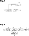
Fig. 4 is a schematic diagram showing a lighting device of a further example; -
Fig. 5 is a schematic diagram showing a lighting device of a further example; -
Fig. 6 is a schematic diagram showing a lighting device of a further example; -
Fig. 7 is a schematic diagram showing a lighting device of a further example; -
Fig. 8 is a block diagram illustrating the electrical configuration of a lighting device of a further example; -
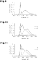
Fig. 9 is a chart of the spectrum from a short wavelength light source in a lighting device of a further example; -
Fig. 10 is a chart of the spectrum from a long wavelength light source unit in a lighting device of a further example; -
Fig. 11 is a chart of the spectrum of synthesized light from short and long wavelength light source units in a lighting device of a further example; and -
Fig. 12 is a chart of the spectrum from a short wavelength light source unit in a lighting device of a further example. - A
lighting device 10 according to one embodiment of the present invention will now be described with reference to the drawings. - As shown in
Fig. 1 , thelighting device 10 of the present embodiment includes anillumination unit 11 and anactivation circuit 12. Theillumination unit 11 externally emits light, and theactivation circuit 12 controls the activation of theillumination unit 11. - The
illumination unit 11 includes twoLED light sources fluorescent body 23. TheLED light sources fluorescent body 23 covers a light emitting surface of theLED light source 22. Further, thefluorescent body 23 emits yellow light when excited upon absorption of light from theLED light source 22. In theillumination unit 11, theLED light source 21 emits a short wavelength light, and thefluorescent body 23 and theLED light source 22 emit a long wavelength light. - As shown in
Fig. 2 , theactivation circuit 12 of thelighting device 10 includes a mainactivation circuit unit 31, a backupactivation circuit unit 32, aswitch circuit unit 33, anactivation detection unit 34, acharge unit 35, apower unit 36, aswitch 37, an outputvarying unit 38, and atime control unit 39. The mainactivation circuit unit 31 is electrically connected to an AC power supply D. Theswitch circuit unit 33 electrically connects the mainactivation circuit unit 31 to the twoLED light sources illumination unit 11. Thus, the twoLED light sources activation circuit unit 31 and theswitch circuit unit 33. This allows for activation of the twoLED light sources activation circuit unit 31 and the AC power supply D form a main power supply unit. - The backup
activation circuit unit 32 is electrically connected to thecharge unit 35. Theoutput varying unit 38 and theswitch circuit unit 33 connect the backupactivation circuit unit 32 to theLED light source 21 of theillumination unit 11. Thecharge unit 35 is electrically connected to thepower unit 36. Theswitch 37, which may be turned on and off, electrically connects thepower unit 36 to the AC power supply D. When theswitch 37 is turned on, thecharge unit 35 accumulates power supplied from the AC power supply D through thepower unit 36. TheLED light source 22 is supplied with power from thecharge unit 35 through the backupactivation circuit unit 32. This allows for activation of theLED light source 22. In the present embodiment, the backupactivation circuit unit 32 and thecharge unit 35 form a backup power supply unit. - The
activation detection unit 34 detects whether or not power is supplied from the AC power supply D to the mainactivation circuit unit 31. When theactivation detection unit 34 determines that theLED light source 21 is not activated (deactivated) theactivation detection unit 34 provides the outputvarying unit 38 with a varying signal. Upon receipt of the varying signal, theoutput varying unit 38 controls theswitch circuit unit 33 to switch to a power line extending through the backupactivation circuit unit 32. More specifically, upon receipt of the varying signal, theoutput varying unit 38 functions to supply the power from the backupactivation circuit unit 32 to theLED light source 21 through the outputvarying unit 38 and theswitch circuit unit 33. - Examples of the operation of the
lighting device 10 under normal and abnormal situations will now be described. - Under a normal situation, power is supplied from the AC power supply D to the main
activation circuit unit 31. The mainactivation circuit unit 31 controls the activation of the twoLED light sources LED light sources illumination unit 11 emits white light (refer toFig. 3A ). When theswitch 37 is ON, power from the AC power supply D is accumulated in thecharge unit 35 through thepower unit 36. - When the supply of power from the AC power supply D is interrupted (abnormal situation) by a wire breakage or the like, the
activation detection unit 34 provides theoutput varying unit 38 with a varying signal. Upon receipt of the varying signal, theoutput varying unit 38 controls theswitch circuit unit 33 to switch to the power line extending through the backupactivation circuit unit 32. Thus, the backupactivation circuit unit 32 is supplied with power from thecharge unit 35 instead of the AC power supply D. Then, for example, when an activation operation is performed with an operation switch (not shown), theLED light source 21 is activated, and theillumination unit 11 emits blue light (refer toFig. 3B ). In this case, theLED light source 22 covered by the yellowfluorescent body 23 is deactivated. This decreases the long wavelength band light output from the LEDlight source 22 to zero. - The human retina has photoreceptor cells including rods, which function under a mesopic vision situation or a scotopic vision situation. Thus, the activation of the
LED light source 21 that emits short wavelength band light (e.g., blue light) improves visibility. - The
lighting device 10 of the present embodiment has the advantages described below. - (1) The
lighting device 10 includes theillumination unit 11, which includes the twoLED light sources output varying unit 38, which is capable of varying the long wavelength band light output from theillumination unit 11. Theoutput varying unit 38 decreases the output of theLED light source 22 to zero. TheLED light source 22 is covered by thefluorescent body 23 that emits the long wavelength band light of theillumination unit 11. Further, theoutput varying unit 38 activates only theLED light source 21 that emits short wavelength band light. Rods function under a mesopic vision situation or a scotopic vision situation. Thus, the activation of theLED light source 21 that emits short wavelength band light (e.g., blue light) improves visibility. The use of the twoLED light sources lighting device 10. Further, the number of theLED light sources lighting device 10. - (2) In the
lighting device 10, when the power supplied to theillumination unit 11 is switched from the power from the main power supply unit to the power from the backup power supply unit, theactivation detection unit 34 provides theoutput varying unit 38 with a varying signal. Upon receipt of the varying signal, theoutput varying unit 38 controls theswitch circuit unit 33 to decrease the output of long wavelength band light. In this manner, changing the power supply source allows for theoutput varying unit 38 to decrease the output of long wavelength band light. - Although not particularly mentioned above, in the above embodiment, the
output varying unit 38 may be configured to gradually decrease the long wavelength band light. This allows for gradual shifting to only the short wavelength band light, and allows for reduction in the time used chromatic adaptation. Thus, a person would not feel discomfort with such a configuration. - Although not particularly mentioned above, in the above embodiment, white light may be emitted until a predetermined time elapses from when the
output varying unit 38 is provided with a varying signal by combining short wavelength band light and long wavelength band light, and the output of the long wavelength band light may be decreased after the predetermined time elapses. More specifically, as shown inFig. 2 , theactivation circuit 12 includes thetime control unit 39 electrically connected to theoutput varying unit 38. Thetime control unit 39 measures the elapsed time from when theoutput varying unit 38 receives the varying signal. Theoutput varying unit 38 controls the switching of theswitch circuit unit 33 after the predetermined time elapses based on the measured elapsed time. - In the above embodiment, the
illumination unit 11 includes the twoLED light sources light source 22 is covered by thefluorescent body 23 to emit white light. Instead, for example, referring toFig. 4 , anLED light source 41 that emits blue light and anLED light source 42 that emits light in the long wavelength band such as orange color may be used to emit white light by combining long wavelength band light, such as the blue light and the orange light. - In the above embodiment, the two
LED light sources Fig. 5 , theillumination unit 11 may include anLED light source 43 that emits white light and anLED light source 44 that emits blue light. During a normal operation, only theLED light source 43 may be activated to emit white light. During a backup operation, only theLED light source 44 may be activated to emit blue light. - In the above embodiment, during a normal operation and a backup operation, at least one of the
LED light sources - For example, referring to
Fig. 6 , theillumination unit 11 may include anLED light source 45 that emits blue light and afluorescent body 46 that emits blue light and afluorescent body 46 that emits yellow (orange) light when excited by the light of theLED light source 45. Further, theillumination unit 11 includes anoutput varying unit 47 that decreases the output of long wavelength band light by cutting or moving thefluorescent body 46 during a backup operation. In this configuration, under a backup operation, the light (blue light) may be emitted from only theLED light source 45. Further, the number ofLED light sources 45 may be reduced. - For example, referring to
Fig. 7 , theillumination unit 11 may include anLED light source 51 that emits white light, aliquid crystal filter 52 arranged opposing an emission surface of theLED light source 51, and a liquidcrystal control unit 53 that controls theliquid crystal filter 52. This allows the liquidcrystal control unit 53 to control theliquid crystal filter 52 and emit light having a short wavelength during a backup situation. - Although not particularly mentioned above, in the above embodiment, for example, referring to
Fig. 8 , theillumination unit 11 may include a lightflux measurement unit 56 that measures the light flux of the twoLED light sources LED light sources flux measurement unit 56 becomes less than or equal to a predetermined value, theoutput varying unit 38 decreases the output of the long wavelength band light.Fig. 8 does not show the backupactivation circuit unit 32 and thecharge unit 35 that are used during a backup operation. - In the above embodiment, the
LED light source 22 emits long wavelength band light, and thefluorescent body 23 and the LEDlight source 21 emit short wavelength band light. Instead, for example, theillumination unit 11 may include a short wavelength light source unit and a long wavelength light source unit that emits, to the short wavelength light source, short wavelength band light having a relatively small output (spectral intensity) and long wavelength band light having a relatively large output. One such example will now be described. - The short wavelength light source unit includes, for example, an LED light source and a fluorescent body excited by the light of the LED light source. Referring to
Fig. 9 , the short wavelength light source unit includes, for example, a first peak wavelength P1 in the proximity of approximately 450 nm and a second peak wavelength P2 in the proximity of approximately 550 nm. When the light output at the first peak wavelength P1 is represented by 1, the short wavelength LED light source is configured so that the light output at the second peak wavelength P2 is approximately 0.3. Further, the short wavelength light source unit is configured so that the correlated color temperature is 10000 K, the average color rendering index Ra is 73, and the S/P ratio is 2.28. The S/P ratio is the ratio of scotopic vision brightness Ls, which is calculated by integrating the spectral luminous efficiency V' (λ) under scotopic vision and the spectral characteristics of a lamp, and the photopic vision brightness Lp, which is calculated by the spectral luminous efficiency V (λ) under photopic vision and the spectral characteristics of a lamp. - The long wavelength light source unit includes, for example, an LED light source and a fluorescent body excited by the light of the LED light source. The long wavelength light source unit emits light of a short wavelength band having a relatively small light output and light of a long wavelength band having a relatively large light output to the short wavelength light source unit. For example, the long wavelength light source unit emits light including spectrum A, shown by the solid line in
Fig. 10 , and spectrum B, shown by the broken line inFig. 10 . The spectrum A of the long wavelength light source unit has a first peak wavelength P1 in the proximity of approximately 455 nm, a second peak wavelength P2 in the proximity of approximately 490 nm, and a third peak wavelength P3 in the proximity of approximately 600 nm. When the light output at the first peak wavelength P1 is represented by 1, the long wavelength light source unit that emits the spectrum A is configured so that the light output at the second peak wavelength P2 is approximately 0.9 and the light output at the third peak wavelength P3 is approximately 0.53. Further, the long wavelength light source unit that emits the spectrum A is configured so that the correlated color temperature is 6800 K, the average color rendering index Ra is 85, and the S/P ratio is 2.79. - In
Fig. 11 , spectrum X shown by the solid line indicates the spectrum of synthesized light when activating the short wavelength light source unit and the long wavelength light source emitting the spectrum A. In this case, the synthesized light has a correlated color temperature of 8000 K, an average color rendering index Ra of 95, and an S/P ratio of 2.62. - Further, the long wavelength light source unit that emits the spectrum B, shown by the broken line in
Fig. 10 , has a first peak wavelength P1 in the proximity of approximately 440 nm and a second peak wavelength P2 in the proximity of approximately 550 nm. When the light output at the first peak wavelength P1 is represented by 1, the long wavelength light source unit that emits the spectrum B is configured so that the light output at the second peak wavelength P2 is approximately 0.43. Further, the long wavelength light source unit that emits the spectrum B is configured so that the correlated color temperature is 7100 K, the average color rendering index Ra is 70, and the S/P ratio is 2.04. - In
Fig. 11 , spectrum Y shown by the broken line indicates the spectrum of synthesized light when activating the short wavelength light source unit and the long wavelength light source emitting the spectrum B. In this case, the synthesized light has a correlated color temperature of 8100 K, an average color rendering index Ra of 71, and an S/P ratio of 2.14. - In the lighting device configured in this manner, as shown in
Fig. 2 , theactivation detection unit 34 detects whether or not the mainactivation circuit unit 31 is supplied with power from the AC power supply D. When the mainactivation circuit unit 31 is supplied with power during a normal operation, the mainactivation circuit unit 31 controls the activation of the short and long wavelength light source units in theillumination unit 11. For example, when an activation operation is performed with an operation switch (not shown), the short and long wavelength light source units are activated so that theillumination unit 11 emits white light (refer toFig. 11 ). - When the supply of power from the AC power supply D is interrupted due to a wire breakage or the like, the
activation detection unit 34 provides theoutput varying unit 38 with a varying signal. Upon receipt of the varying signal, theoutput varying unit 38 controls theswitch circuit unit 33 to switch to the power line extending through the backupactivation circuit unit 32. This supplies the backupactivation circuit unit 32 with power from thecharge unit 35 instead of the AC power supply D. Then, for example, when an activation operation is performed with an operation switch (not shown), only the short wavelength light source unit is activated, and theillumination unit 11 emits light having a correlated color temperature of 10000 K (refer toFig. 9 ). - Light having a correlated color temperature of 10000 K is in a correlated color temperature range (2500 K to 10000 K) used as an LED module for emitting white light as specified in JIS C8155:2010 "General Lighting LED Module, Capacity Requirements". Thus, white light may be emitted during a backup operation. Further, when the long wavelength light source unit is deactivated, only the short wavelength light source unit having a relatively high color temperature is activated. As a result, the S/P ratio during the backup operation is higher than that during a normal operation. Further, the light from the short wavelength light source unit, as a single body, has an average color rendering index Ra of 70 or greater. Thus, sufficiently high color rendering may be maintained.
- The short wavelength light source unit and the long wavelength light source unit of the above modified examples are activated with the same light flux during normal operation. However, the light flux ratio may be varied. Further, in the above modified examples, the long wavelength light source unit is activated. Instead, the long wavelength light source unit may be dimmed. In this manner, the long wavelength light source unit may be activated or dimmed so that in the light output of the light emitted from the
illumination unit 11, the light output of the long wavelength band is greater than the light output of the short wavelength band. The short wavelength light source unit does not have to have the characteristics shown inFig. 9 and may have the characteristics shown by the solid line or broken line inFig. 12 . - In the above embodiment, when receiving the varying signal, the
output varying unit 38 supplies power from the backupactivation circuit unit 32 to theLED light source 21 through theoutput varying unit 38 and theswitch circuit unit 33. Instead, when receiving the varying signal, theoutput varying unit 38 may supply power from the backupactivation circuit unit 32 through only theswitch circuit unit 33. In this case, theactivation detection unit 34 may provide the varying signal to theswitch circuit unit 33 so that theswitch circuit unit 33 switches to a power line extending through the backupactivation circuit unit 32.
Claims (6)
- A lighting device (10) comprising:an illumination unit (11) including at least one, maximum two LED light sources (21,22), wherein the at least one, maximum two LED light sources (21,22) are adapted to emit light of a short wavelength band and light of a long wavelength band; and an output varying unit (38) adapted to vary an output of at least the long wavelength band light, and to receive a varying signal, and a main power supply unit (31) adapted to supply power to the illumination unit (11),characterized in that:the lighting device (10) further comprises a backup power supply unit (35) adapted to supply power to the illumination unit (11) during a backup situation in which the supply of power from the main power supply unit (31) is interrupted, and wherein the output varying unit (38) is adapted to decrease the output of at least the long wavelength band light when the output varying unit (38) receives the varying signal, wherein the varying signal indicates that the power supplied to the illumination unit (11) has been switched from the power supplied by the main power supply unit (31) to the power supplied by the backup power supply unit (35).
- The lighting device (10) according to claim 1, wherein the output varying unit (38) is adapted to gradually decrease the output of at least the long wavelength band light.
- The lighting device (10) according to claim 1, wherein
the illumination unit (11) is adapted to emit white light by emitting the short wavelength band light and the long wavelength band light; and
the output varying unit (38) is adapted to combine the short wavelength band light and the long wavelength band light to emit the white light until a predetermined time elapses from when receiving the varying signal, and the output varying unit (38) is adapted to decrease the output of at least the long wavelength band light after the predetermined time elapses. - The lighting device (10) according to any one of claims 1-3, further comprising a light flux measurement unit (56) adapted to measure light flux of the at least one, maximum two LED light sources (21,22), wherein the output varying unit (38) is adapted to decrease the output of at least the long wavelength band light when the light flux measured by the light flux measurement unit (56) becomes less than or equal to a predetermined value.
- The lighting device (10) according to any one of claims 1-4, further comprising:a detection unit adapted to provide the output varying unit (38) with the varying signal when detecting that the supply of power from the main power supply unit (31) has been interrupted.
- The lighting device (10) according to claim 5, wherein when the output varying unit (38) receives the varying signal, the output varying unit (38) is adapted to switch the power supplied to the illumination unit (11) from the power supplied by the main power supply unit (31) to the power supplied by the backup power supply unit (35).
Applications Claiming Priority (1)
| Application Number | Priority Date | Filing Date | Title |
|---|---|---|---|
| JP2012157686A JP2013058469A (en) | 2011-08-18 | 2012-07-13 | Illumination device |
Publications (3)
| Publication Number | Publication Date |
|---|---|
| EP2685786A2 EP2685786A2 (en) | 2014-01-15 |
| EP2685786A3 EP2685786A3 (en) | 2014-08-27 |
| EP2685786B1 true EP2685786B1 (en) | 2017-09-13 |
Family
ID=48670431
Family Applications (1)
| Application Number | Title | Priority Date | Filing Date |
|---|---|---|---|
| EP13173318.0A Active EP2685786B1 (en) | 2012-07-13 | 2013-06-24 | Lighting device |
Country Status (2)
| Country | Link |
|---|---|
| EP (1) | EP2685786B1 (en) |
| CN (1) | CN103542283B (en) |
Family Cites Families (10)
| Publication number | Priority date | Publication date | Assignee | Title |
|---|---|---|---|---|
| JPH03159820A (en) | 1989-11-16 | 1991-07-09 | Daihatsu Motor Co Ltd | Power unit device for automobile |
| US6577073B2 (en) * | 2000-05-31 | 2003-06-10 | Matsushita Electric Industrial Co., Ltd. | Led lamp |
| GB2403062B (en) * | 2003-06-18 | 2006-03-01 | Gen Electric | Light sources for improving visual perception under mesopic lighting conditions |
| JP4458804B2 (en) * | 2003-10-17 | 2010-04-28 | シチズン電子株式会社 | White LED |
| JP3977364B2 (en) * | 2004-09-03 | 2007-09-19 | キヤノン株式会社 | Exposure apparatus and device manufacturing method |
| CN201221693Y (en) * | 2008-06-11 | 2009-04-15 | 朱志明 | LED ball bulb lamp |
| CN201242128Y (en) * | 2008-06-27 | 2009-05-20 | 中海阳(北京)新能源电力工程有限公司 | LED ball bulb lamp |
| TWI374996B (en) * | 2009-04-15 | 2012-10-21 | Semi Photonics Co Ltd | Light emitting device with high cri and high luminescence efficiency |
| US8264155B2 (en) * | 2009-10-06 | 2012-09-11 | Cree, Inc. | Solid state lighting devices providing visible alert signals in general illumination applications and related methods of operation |
| JP3159820U (en) * | 2010-03-16 | 2010-06-03 | 彰男 糠谷 | Lighting device |
-
2013
- 2013-06-24 EP EP13173318.0A patent/EP2685786B1/en active Active
- 2013-07-10 CN CN201310287615.2A patent/CN103542283B/en active Active
Non-Patent Citations (1)
| Title |
|---|
| None * |
Also Published As
| Publication number | Publication date |
|---|---|
| CN103542283A (en) | 2014-01-29 |
| EP2685786A2 (en) | 2014-01-15 |
| EP2685786A3 (en) | 2014-08-27 |
| CN103542283B (en) | 2016-03-16 |
Similar Documents
| Publication | Publication Date | Title |
|---|---|---|
| US9844115B2 (en) | Systems and methods for optimizing power and control of a multicolored lighting system | |
| EP2792218B1 (en) | Emergency lighting devices with led strings | |
| CN102563417B (en) | Illuminating device | |
| US20090157567A1 (en) | Led lighting system | |
| CN212644309U (en) | Novel flexible LED light-emitting lamp area | |
| US9084311B2 (en) | Lighting device | |
| US9247604B2 (en) | Lighting device | |
| CN110139422A (en) | Current-limiting type electron rectifier and the fluorescent tube for using the current-limiting type electron rectifier | |
| WO2013089659A2 (en) | Solid state lighting devices providing visible alert signals in general illumination applications and related methods of operation | |
| US6331062B1 (en) | LED flashlight | |
| JP2012028222A (en) | Power supply unit for led lamp and led lamp system | |
| US7963665B2 (en) | Vehicle light and LED package | |
| JP2011181245A (en) | Led lighting device | |
| EP2685786A2 (en) | Lighting device | |
| CN202708928U (en) | Multipurpose energy-saving searchlight | |
| EP2403320A1 (en) | LED lamp system | |
| JP2014017058A (en) | Luminaire | |
| JP6593576B2 (en) | Emergency lighting system | |
| JP2014127351A (en) | Emergency lighting apparatus | |
| KR200396946Y1 (en) | A lamp for sleep using a light emitting diode | |
| CN210609786U (en) | Current-limiting electronic rectifier and lamp tube with same | |
| CN209309712U (en) | A kind of LEDbulb lamp | |
| KR101378525B1 (en) | Led lighting apparatus | |
| JP2019129114A (en) | Light-emitting body, light housing device, and lighting device | |
| JP2016507139A (en) | Dimmable light-emitting diode lamp |
Legal Events
| Date | Code | Title | Description |
|---|---|---|---|
| PUAI | Public reference made under article 153(3) epc to a published international application that has entered the european phase |
Free format text: ORIGINAL CODE: 0009012 |
|
| 17P | Request for examination filed |
Effective date: 20130624 |
|
| AK | Designated contracting states |
Kind code of ref document: A2 Designated state(s): AL AT BE BG CH CY CZ DE DK EE ES FI FR GB GR HR HU IE IS IT LI LT LU LV MC MK MT NL NO PL PT RO RS SE SI SK SM TR |
|
| AX | Request for extension of the european patent |
Extension state: BA ME |
|
| PUAL | Search report despatched |
Free format text: ORIGINAL CODE: 0009013 |
|
| AK | Designated contracting states |
Kind code of ref document: A3 Designated state(s): AL AT BE BG CH CY CZ DE DK EE ES FI FR GB GR HR HU IE IS IT LI LT LU LV MC MK MT NL NO PL PT RO RS SE SI SK SM TR |
|
| AX | Request for extension of the european patent |
Extension state: BA ME |
|
| RIC1 | Information provided on ipc code assigned before grant |
Ipc: H05B 33/08 20060101AFI20140722BHEP |
|
| RAP1 | Party data changed (applicant data changed or rights of an application transferred) |
Owner name: PANASONIC INTELLECTUAL PROPERTY MANAGEMENT CO., LT |
|
| GRAP | Despatch of communication of intention to grant a patent |
Free format text: ORIGINAL CODE: EPIDOSNIGR1 |
|
| STAA | Information on the status of an ep patent application or granted ep patent |
Free format text: STATUS: GRANT OF PATENT IS INTENDED |
|
| INTG | Intention to grant announced |
Effective date: 20170407 |
|
| GRAS | Grant fee paid |
Free format text: ORIGINAL CODE: EPIDOSNIGR3 |
|
| GRAA | (expected) grant |
Free format text: ORIGINAL CODE: 0009210 |
|
| STAA | Information on the status of an ep patent application or granted ep patent |
Free format text: STATUS: THE PATENT HAS BEEN GRANTED |
|
| AK | Designated contracting states |
Kind code of ref document: B1 Designated state(s): AL AT BE BG CH CY CZ DE DK EE ES FI FR GB GR HR HU IE IS IT LI LT LU LV MC MK MT NL NO PL PT RO RS SE SI SK SM TR |
|
| REG | Reference to a national code |
Ref country code: GB Ref legal event code: FG4D |
|
| REG | Reference to a national code |
Ref country code: CH Ref legal event code: EP |
|
| REG | Reference to a national code |
Ref country code: IE Ref legal event code: FG4D |
|
| REG | Reference to a national code |
Ref country code: AT Ref legal event code: REF Ref document number: 929389 Country of ref document: AT Kind code of ref document: T Effective date: 20171015 |
|
| REG | Reference to a national code |
Ref country code: DE Ref legal event code: R096 Ref document number: 602013026471 Country of ref document: DE |
|
| REG | Reference to a national code |
Ref country code: NL Ref legal event code: MP Effective date: 20170913 |
|
| REG | Reference to a national code |
Ref country code: LT Ref legal event code: MG4D |
|
| PG25 | Lapsed in a contracting state [announced via postgrant information from national office to epo] |
Ref country code: HR Free format text: LAPSE BECAUSE OF FAILURE TO SUBMIT A TRANSLATION OF THE DESCRIPTION OR TO PAY THE FEE WITHIN THE PRESCRIBED TIME-LIMIT Effective date: 20170913 Ref country code: NO Free format text: LAPSE BECAUSE OF FAILURE TO SUBMIT A TRANSLATION OF THE DESCRIPTION OR TO PAY THE FEE WITHIN THE PRESCRIBED TIME-LIMIT Effective date: 20171213 Ref country code: SE Free format text: LAPSE BECAUSE OF FAILURE TO SUBMIT A TRANSLATION OF THE DESCRIPTION OR TO PAY THE FEE WITHIN THE PRESCRIBED TIME-LIMIT Effective date: 20170913 Ref country code: FI Free format text: LAPSE BECAUSE OF FAILURE TO SUBMIT A TRANSLATION OF THE DESCRIPTION OR TO PAY THE FEE WITHIN THE PRESCRIBED TIME-LIMIT Effective date: 20170913 Ref country code: LT Free format text: LAPSE BECAUSE OF FAILURE TO SUBMIT A TRANSLATION OF THE DESCRIPTION OR TO PAY THE FEE WITHIN THE PRESCRIBED TIME-LIMIT Effective date: 20170913 |
|
| REG | Reference to a national code |
Ref country code: AT Ref legal event code: MK05 Ref document number: 929389 Country of ref document: AT Kind code of ref document: T Effective date: 20170913 |
|
| PG25 | Lapsed in a contracting state [announced via postgrant information from national office to epo] |
Ref country code: ES Free format text: LAPSE BECAUSE OF FAILURE TO SUBMIT A TRANSLATION OF THE DESCRIPTION OR TO PAY THE FEE WITHIN THE PRESCRIBED TIME-LIMIT Effective date: 20170913 Ref country code: LV Free format text: LAPSE BECAUSE OF FAILURE TO SUBMIT A TRANSLATION OF THE DESCRIPTION OR TO PAY THE FEE WITHIN THE PRESCRIBED TIME-LIMIT Effective date: 20170913 Ref country code: GR Free format text: LAPSE BECAUSE OF FAILURE TO SUBMIT A TRANSLATION OF THE DESCRIPTION OR TO PAY THE FEE WITHIN THE PRESCRIBED TIME-LIMIT Effective date: 20171214 Ref country code: RS Free format text: LAPSE BECAUSE OF FAILURE TO SUBMIT A TRANSLATION OF THE DESCRIPTION OR TO PAY THE FEE WITHIN THE PRESCRIBED TIME-LIMIT Effective date: 20170913 Ref country code: BG Free format text: LAPSE BECAUSE OF FAILURE TO SUBMIT A TRANSLATION OF THE DESCRIPTION OR TO PAY THE FEE WITHIN THE PRESCRIBED TIME-LIMIT Effective date: 20171213 |
|
| PG25 | Lapsed in a contracting state [announced via postgrant information from national office to epo] |
Ref country code: NL Free format text: LAPSE BECAUSE OF FAILURE TO SUBMIT A TRANSLATION OF THE DESCRIPTION OR TO PAY THE FEE WITHIN THE PRESCRIBED TIME-LIMIT Effective date: 20170913 |
|
| PG25 | Lapsed in a contracting state [announced via postgrant information from national office to epo] |
Ref country code: RO Free format text: LAPSE BECAUSE OF FAILURE TO SUBMIT A TRANSLATION OF THE DESCRIPTION OR TO PAY THE FEE WITHIN THE PRESCRIBED TIME-LIMIT Effective date: 20170913 Ref country code: PL Free format text: LAPSE BECAUSE OF FAILURE TO SUBMIT A TRANSLATION OF THE DESCRIPTION OR TO PAY THE FEE WITHIN THE PRESCRIBED TIME-LIMIT Effective date: 20170913 Ref country code: CZ Free format text: LAPSE BECAUSE OF FAILURE TO SUBMIT A TRANSLATION OF THE DESCRIPTION OR TO PAY THE FEE WITHIN THE PRESCRIBED TIME-LIMIT Effective date: 20170913 |
|
| PG25 | Lapsed in a contracting state [announced via postgrant information from national office to epo] |
Ref country code: EE Free format text: LAPSE BECAUSE OF FAILURE TO SUBMIT A TRANSLATION OF THE DESCRIPTION OR TO PAY THE FEE WITHIN THE PRESCRIBED TIME-LIMIT Effective date: 20170913 Ref country code: IT Free format text: LAPSE BECAUSE OF FAILURE TO SUBMIT A TRANSLATION OF THE DESCRIPTION OR TO PAY THE FEE WITHIN THE PRESCRIBED TIME-LIMIT Effective date: 20170913 Ref country code: SK Free format text: LAPSE BECAUSE OF FAILURE TO SUBMIT A TRANSLATION OF THE DESCRIPTION OR TO PAY THE FEE WITHIN THE PRESCRIBED TIME-LIMIT Effective date: 20170913 Ref country code: IS Free format text: LAPSE BECAUSE OF FAILURE TO SUBMIT A TRANSLATION OF THE DESCRIPTION OR TO PAY THE FEE WITHIN THE PRESCRIBED TIME-LIMIT Effective date: 20180113 Ref country code: AT Free format text: LAPSE BECAUSE OF FAILURE TO SUBMIT A TRANSLATION OF THE DESCRIPTION OR TO PAY THE FEE WITHIN THE PRESCRIBED TIME-LIMIT Effective date: 20170913 Ref country code: SM Free format text: LAPSE BECAUSE OF FAILURE TO SUBMIT A TRANSLATION OF THE DESCRIPTION OR TO PAY THE FEE WITHIN THE PRESCRIBED TIME-LIMIT Effective date: 20170913 |
|
| REG | Reference to a national code |
Ref country code: DE Ref legal event code: R097 Ref document number: 602013026471 Country of ref document: DE |
|
| PLBE | No opposition filed within time limit |
Free format text: ORIGINAL CODE: 0009261 |
|
| STAA | Information on the status of an ep patent application or granted ep patent |
Free format text: STATUS: NO OPPOSITION FILED WITHIN TIME LIMIT |
|
| PG25 | Lapsed in a contracting state [announced via postgrant information from national office to epo] |
Ref country code: DK Free format text: LAPSE BECAUSE OF FAILURE TO SUBMIT A TRANSLATION OF THE DESCRIPTION OR TO PAY THE FEE WITHIN THE PRESCRIBED TIME-LIMIT Effective date: 20170913 |
|
| 26N | No opposition filed |
Effective date: 20180614 |
|
| PG25 | Lapsed in a contracting state [announced via postgrant information from national office to epo] |
Ref country code: SI Free format text: LAPSE BECAUSE OF FAILURE TO SUBMIT A TRANSLATION OF THE DESCRIPTION OR TO PAY THE FEE WITHIN THE PRESCRIBED TIME-LIMIT Effective date: 20170913 |
|
| REG | Reference to a national code |
Ref country code: CH Ref legal event code: PL |
|
| GBPC | Gb: european patent ceased through non-payment of renewal fee |
Effective date: 20180624 |
|
| REG | Reference to a national code |
Ref country code: BE Ref legal event code: MM Effective date: 20180630 |
|
| REG | Reference to a national code |
Ref country code: IE Ref legal event code: MM4A |
|
| PG25 | Lapsed in a contracting state [announced via postgrant information from national office to epo] |
Ref country code: MC Free format text: LAPSE BECAUSE OF FAILURE TO SUBMIT A TRANSLATION OF THE DESCRIPTION OR TO PAY THE FEE WITHIN THE PRESCRIBED TIME-LIMIT Effective date: 20170913 Ref country code: LU Free format text: LAPSE BECAUSE OF NON-PAYMENT OF DUE FEES Effective date: 20180624 |
|
| PG25 | Lapsed in a contracting state [announced via postgrant information from national office to epo] |
Ref country code: FR Free format text: LAPSE BECAUSE OF NON-PAYMENT OF DUE FEES Effective date: 20180630 Ref country code: IE Free format text: LAPSE BECAUSE OF NON-PAYMENT OF DUE FEES Effective date: 20180624 Ref country code: GB Free format text: LAPSE BECAUSE OF NON-PAYMENT OF DUE FEES Effective date: 20180624 Ref country code: LI Free format text: LAPSE BECAUSE OF NON-PAYMENT OF DUE FEES Effective date: 20180630 Ref country code: CH Free format text: LAPSE BECAUSE OF NON-PAYMENT OF DUE FEES Effective date: 20180630 |
|
| PG25 | Lapsed in a contracting state [announced via postgrant information from national office to epo] |
Ref country code: BE Free format text: LAPSE BECAUSE OF NON-PAYMENT OF DUE FEES Effective date: 20180630 |
|
| REG | Reference to a national code |
Ref country code: DE Ref legal event code: R079 Ref document number: 602013026471 Country of ref document: DE Free format text: PREVIOUS MAIN CLASS: H05B0033080000 Ipc: H05B0045000000 |
|
| PG25 | Lapsed in a contracting state [announced via postgrant information from national office to epo] |
Ref country code: MT Free format text: LAPSE BECAUSE OF NON-PAYMENT OF DUE FEES Effective date: 20180624 |
|
| PG25 | Lapsed in a contracting state [announced via postgrant information from national office to epo] |
Ref country code: TR Free format text: LAPSE BECAUSE OF FAILURE TO SUBMIT A TRANSLATION OF THE DESCRIPTION OR TO PAY THE FEE WITHIN THE PRESCRIBED TIME-LIMIT Effective date: 20170913 |
|
| PG25 | Lapsed in a contracting state [announced via postgrant information from national office to epo] |
Ref country code: HU Free format text: LAPSE BECAUSE OF FAILURE TO SUBMIT A TRANSLATION OF THE DESCRIPTION OR TO PAY THE FEE WITHIN THE PRESCRIBED TIME-LIMIT; INVALID AB INITIO Effective date: 20130624 Ref country code: PT Free format text: LAPSE BECAUSE OF FAILURE TO SUBMIT A TRANSLATION OF THE DESCRIPTION OR TO PAY THE FEE WITHIN THE PRESCRIBED TIME-LIMIT Effective date: 20170913 |
|
| PG25 | Lapsed in a contracting state [announced via postgrant information from national office to epo] |
Ref country code: MK Free format text: LAPSE BECAUSE OF NON-PAYMENT OF DUE FEES Effective date: 20170913 Ref country code: CY Free format text: LAPSE BECAUSE OF FAILURE TO SUBMIT A TRANSLATION OF THE DESCRIPTION OR TO PAY THE FEE WITHIN THE PRESCRIBED TIME-LIMIT Effective date: 20170913 |
|
| PG25 | Lapsed in a contracting state [announced via postgrant information from national office to epo] |
Ref country code: AL Free format text: LAPSE BECAUSE OF FAILURE TO SUBMIT A TRANSLATION OF THE DESCRIPTION OR TO PAY THE FEE WITHIN THE PRESCRIBED TIME-LIMIT Effective date: 20170913 |
|
| PGFP | Annual fee paid to national office [announced via postgrant information from national office to epo] |
Ref country code: DE Payment date: 20250618 Year of fee payment: 13 |