EP2685659A2 - Method and apparatus for delivery notification of non-access stratum retransmission - Google Patents
Method and apparatus for delivery notification of non-access stratum retransmission Download PDFInfo
- Publication number
- EP2685659A2 EP2685659A2 EP13187735.9A EP13187735A EP2685659A2 EP 2685659 A2 EP2685659 A2 EP 2685659A2 EP 13187735 A EP13187735 A EP 13187735A EP 2685659 A2 EP2685659 A2 EP 2685659A2
- Authority
- EP
- European Patent Office
- Prior art keywords
- message
- pdcp
- handover
- rrc
- wtru
- Prior art date
- Legal status (The legal status is an assumption and is not a legal conclusion. Google has not performed a legal analysis and makes no representation as to the accuracy of the status listed.)
- Withdrawn
Links
Images



Classifications
-
- H—ELECTRICITY
- H04—ELECTRIC COMMUNICATION TECHNIQUE
- H04L—TRANSMISSION OF DIGITAL INFORMATION, e.g. TELEGRAPHIC COMMUNICATION
- H04L1/00—Arrangements for detecting or preventing errors in the information received
- H04L1/12—Arrangements for detecting or preventing errors in the information received by using return channel
- H04L1/16—Arrangements for detecting or preventing errors in the information received by using return channel in which the return channel carries supervisory signals, e.g. repetition request signals
- H04L1/18—Automatic repetition systems, e.g. Van Duuren systems
- H04L1/1867—Arrangements specially adapted for the transmitter end
- H04L1/1874—Buffer management
- H04L1/1877—Buffer management for semi-reliable protocols, e.g. for less sensitive applications like streaming video
-
- H—ELECTRICITY
- H04—ELECTRIC COMMUNICATION TECHNIQUE
- H04W—WIRELESS COMMUNICATION NETWORKS
- H04W36/00—Hand-off or reselection arrangements
- H04W36/08—Reselecting an access point
-
- H—ELECTRICITY
- H04—ELECTRIC COMMUNICATION TECHNIQUE
- H04W—WIRELESS COMMUNICATION NETWORKS
- H04W76/00—Connection management
- H04W76/20—Manipulation of established connections
- H04W76/22—Manipulation of transport tunnels
Definitions
- This application is related to wireless communications.
- FIG. 1 shows an overview of an Evolved Universal Mobile Telecommunications System (UMTS) Terrestrial Radio Access Network (E-UTRAN) 100 in accordance with the prior art.
- E-UTRAN 100 includes three eNodeBs (eNBs) 102, however, any number of eNBs may be included in E-UTRAN 100.
- the eNBs 102 are interconnected by an X2 interface 108.
- the eNBs 102 are also connected by an S1 interface 106 to the Evolved Packet Core (EPC) 104.
- the EPC 104 includes a Mobility Management Entity (MME) 108 and a Serving Gateway (S-GW) 110.
- MME Mobility Management Entity
- S-GW Serving Gateway
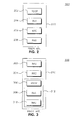
- FIG. 2 shows an LTE user-plane protocol stack 200 in accordance with the prior art.
- the protocol stack 200 is located in a WTRU 210 and includes the packet data control protocol (PDCP) 202, the radio link control (RLC) 204, the medium access control (MAC) 206 and the physical layer (PHY) 208.
- the protocol stack 200 may also reside in an eNB (not shown).
- FIG 3 shows an LTE control plane protocol stack 300 in the WTRU 210 of Figure 2 .
- the control plane protocol stack 300 includes the non-access stratum (NAS) 302 and a radio resource control (RRC) 304. Also included are the PDCP 306, RLC 308 and MAC 310, which together form the layer 2 sublayer 312.
- NAS non-access stratum
- RRC radio resource control
- a WTRU 210 may transmit uplink (UL) system data units (SDUs) from the PDCP (206). If the WTRU 210 does not receive a notice that the SDUs were successfully delivered, the WTRU 210 may retransmit the SDUs. The WTRU 210 may use a PDCP status report, received from an eNB, to determine which uplink PDCP SDUs to retransmit. The WTRU 210 may also use the report to discard SDUs, if the SDUs were received or acknowledged by the status report.
- UL uplink
- SDUs system data units
- a target eNB may retransmit, to the WTRU 210, downlink PDCP SDUs that were forwarded by a source eNB.
- the WTRU 210 may transmit a PDCP status report to the target eNB.
- the target eNB may utilize the PDCP status report to determine which PDCP SDUs to retransmit to the WTRU 210.
- the target eNB may also discard downlink PDCP SDUs, if the SDUs were received or acknowledged by PDCP status report.
- the WTRU 210 may reorder the SDUs and eliminate duplicates.
- the WTRU 210 may then deactivate any functions based on a timer, such as a flush timer, for example.
- a timer such as a flush timer
- the RLC 204 may indicate that handover has occurred and the PDCP 202 may reinitialize state variables such as a PDCP sequence number (SN) and a hyper frame number (HFN).
- the state variables may also be set to zero. All PDCP SDUs and PDCP PDUs that have been previously stored may be discarded.
- the access stratum (AS) (not shown) may provide an indication of an NAS message transmission failure, if the failure occurred due to handover or cell selection.
- a method and apparatus for data delivery confirmation in a wireless transmit receive unit (WTRU). This may include transmitting an uplink (UL) message, performing a mobility operation, determining that the UL message is not acknowledged, and generating a delivery failure message.
- the mobility operation may be a handover or a radio resource control (RRC) connection reestablishment.
- RRC radio resource control
- a message including the delivery failure message may be passed between protocol layers to a non-access stratum layer.
- FIG 1 shows an overview of an E-UTRAN in accordance with the prior art
- FIG. 2 shows an LTE user-plane protocol stack in accordance with the prior art
- FIG. 3 shows an LTE control-plane protocol stack in accordance with the prior art
- Figure 4 shows an example wireless communication system including a plurality of WTRUs and an eNB in accordance with one embodiment
- Figure 5 is a block diagram of a WTRU and the eNB of Figure 4 ;
- FIG. 6A is a block diagram of an RRC level acknowledgement method in accordance with one embodiment
- FIG. 6B is a block diagram of an RRC level acknowledgement method in accordance with an alternative embodiment
- FIG. 6C is a block diagram of an RRC level acknowledgement method in accordance with another embodiment
- Figure 7 is a block diagram of a method of direct notification of delivery in accordance with one embodiment
- FIG. 8 is a block diagram of a notification method 800 in accordance with one embodiment.
- FIG. 9 is a block diagram of a notification method 900 in accordance with another embodiment.
- wireless transmit/receive unit includes but is not limited to a user equipment (UE), a mobile station, a fixed or mobile subscriber unit, a pager, a cellular telephone, a personal digital assistant (PDA), a computer, or any other type of user device capable of operating in a wireless environment.
- base station includes but is not limited to a Node-B, a site controller, an access point (AP), or any other type of interfacing device capable of operating in a wireless environment.
- delivery notification “delivery confirmation”, “delivery indication”, “transmission confirmation”, and “transmission indication” are used interchangeably hereinafter.
- the terms “upper layer” and “lower layer” are relative terms. Each layer in a protocol stack, including the NAS, RRC, PDCP, RLC, and MAC, is an upper layer in relation to any layer below it in the protocol stack. Therefore, for example, the NAS would be an upper layer in relation to the RRC, PDCP, RLC and MAC layers whereas the RLC is only an upper layer in relation to the MAC layer.
- Figure 4 shows a wireless communication system 400 including a plurality of WTRUs 410 and an e Node B (eNB) 420. As shown in Figure 4 , the WTRUs 410 are in communication with the eNB 420. Although three WTRUs 410 and one eNB 420 are shown in Figure 4 , it should be noted that any combination of wireless and wired devices may be included in the wireless communication system 400.
- eNB e Node B
- FIG 5 is a functional block diagram 500 of a WTRU 410 and the eNB 420 of the wireless communication system 400 of Figure 4 .
- the WTRU 410 is in communication with the eNB 420.
- the WTRU 410 is configured with both a user plane protocol stack (100 of Figure 1 ) and control plane protocol stack (200 of Figure 2 ).
- Each component in a stack is configured to communicate with components above and below it in the stack.
- each component in a stack is configured to communicate with its peer component in a peer protocol stack.
- the WTRU 410 includes a processor 515, a receiver 516, a transmitter 517, and an antenna 518.
- the WTRU 410 may also include a user interface 518, which may include, but is not limited to, an LCD or LED screen, a touch screen, a keyboard, a stylus, or any other typical input/output device.
- the WTRU 410 may also include memory 519, both volatile and non-volatile as well as interfaces 520 to other WTRU's, such as USB ports, serial ports and the like.
- the receiver 516 and the transmitter 517 are in communication with the processor 515.
- the antenna 518 is in communication with both the receiver 516 and the transmitter 517 to facilitate the transmission and reception of wireless data.
- the eNB 420 includes a processor 525, a receiver 526, a transmitter 527, and an antenna 528.
- the receiver 526 and the transmitter 527 are in communication with the processor 525.
- the antenna 528 is in communication with both the receiver 526 and the transmitter 527 to facilitate the transmission and reception of wireless data.
- a WTRU and an eNB may operate in acknowledge mode (AM) or unacknowledged mode (UM).
- AM acknowledge mode
- UM unacknowledged mode
- a transmitting entity may receive an acknowledgment if a data packet, such as a PDU or an SDU, is successfully transmitted to a receiving entity.
- an RLC entity may generate a data packet and the packet may be transmitted.
- the receiving RLC entity may receive the packet and may generate an RLC status report that may be transmitted back to the transmitting RLC entity.
- the RLC status report may include an indication to show if transmission of the packet was successful, For example, if a WTRU transmits a set of RLC PDUs, and all the transmitted RLC PDUs were acknowledged by the receiving entity in an RLC status report, then delivery may be deemed successful. However, if one of the RLC PDUs was negatively acknowledged, and the packet was not retransmitted or is discarded, then the transmitting entity may receive an RLC status report that includes an indication of unsuccessful
- Another indication that the RLC PDU was not successfully delivered may be provided to the transmitting RLC entity without a status report. For example, if the RLC entity has been reset or reestablished and at least one RLC packet has been negatively acknowledged or has not been positively acknowledged by the receiving RLC, the transmitting RLC may determine that delivery was not successful,
- a PDCP may send a packet to an RLC.
- the RLC may transmit the packet and send an RLC delivery confirmation to the PDCP.
- the PDCP may provide a delivery indicator to the upper layer.
- An indication of successful delivery of the PDCP packet may be an indicator provided by the RLC entity.
- the PDCP may provide the indicator to the upper layer, such as the RRC, for example, if it receives an indication of success from the lower layer, such as the RLC, for example.
- the PDCP may transmit an indication of unsuccessful delivery if the PDCP receives a failure notification from the lower layer.
- an indication of delivery failure may be provided to the RRC from the PDCP, if the PDCP discards the packet prior to submitting it to the RLC layer.
- the PDCP status report function may be used to determine the status of the delivery of a PDCP packet.
- An SRB that supports NAS messages may also support the exchange of PDCP status reports.
- the SRB may be used to convey information on missing or acknowledged PDCP packets.
- the PDCP status report may be used to determine the status of the delivery of a PDCP SDU.
- Each PDCP SDU has an associated sequence number.
- the PDCP sequence number (SN) associated with the first SDU to be transmitted to the target cell after handover may be continued from the SN of the last SDU delivered to the source cell before handover. In other words, the SNs are continued from the source to the target, rather than starting with a new SN in the target cell.
- the SRB uplink (UL) and/or downlink (DL) PDCP sequence number (SN) context can be exchanged between the source and the target eNB.
- the PDCP SN may also be retained in the WTRU.
- a WTRU or eNB may create the PDCP status report using the pre-handover SN.
- the PDCP status report may be exchanged in the source eNB.
- PDCP status reports for SRBs provide delivery confirmation to upper layers, such as an RRC and NAS, for example.
- the upper layer will then take the appropriate action, based on the status report.
- FIG. 6A is a block diagram of an RRC level acknowledgement method 600 in accordance with one embodiment.
- the NAS 602 passes a message 604 to the RRC 606.
- the RRC 606 processes the message 604 and passes an RRC message 608 to the PDCP 610.
- the PDCP 610 passes a PDCP SDU 614 to lower layers for transmission.
- the PDCP 610 may pass a delivery status indicator 612 to the NAS 602 that includes an indication if the delivery of the PDCP SDU 614 was successful or unsuccessful.
- the indicator 612 may show a successful delivery if the PDCP 610 receives an indication that delivery of the PDCP SDU 614 was successful.
- the PDCP 610 may determine that delivery of the PDCP SDU 614 was not successful, and the delivery status indicator 612 will indicate an unsuccessful delivery.
- ACK acknowledgement
- NACK non-acknowledgement
- FIG. 6B is a block diagram of an RRC level acknowledgement method 620 in accordance with another embodiment.
- the RRC 606 relies on the PDCP 608 to provide delivery notification to the NAS 602.
- the RRC 606 may also directly provide delivery notification to the NAS 602.
- the NAS 602 passes a message 604 to the RRC 606.
- the RRC 606 sends a message 624 directly to a peer RRC 622.
- the RRC 606 may send a delivery notification 626 directly to the NAS 602 that indicates a failed delivery.
- the NAS 602 may stop all timers and retransmit the message 604.
- the RRC 606 may also provide the delivery notification 626 to the NAS 602 if the RRC 606 receives an indication to retransmit the NAS message in a handover command or through additional signaling in the source or target cell.
- the RRC 606 may provide a delivery notification 626 to the upper layer, for example, the NAS 602 or to lower layers, for example, the PDCP 610.
- the notification may include a notice that the RRC 606 received the handover command, or executed a handover, cell selection or cell reselection.
- the RRC 606 may also provide a notification of another event that may trigger a NAS 602 retransmission or delivery notification to the NAS 602 or the PDCP 610.
- FIG. 6C is a block diagram of an RRC level acknowledgement method 630 in accordance with an alternative embodiment.
- the RRC 606 sets a bit in a header of an RRC message 632 to request an RRC level acknowledgement from a peer RRC entity 622.
- the peer RRC entity 622 then sends an RRC level acknowledgment 636. If no acknowledgment is received within a certain time, a delivery notification of failed transmission 634 is provided to the NAS 602 at handover. A lack of acknowledgement from the peer RRC entity 622 may also be used to trigger RRC level retransmission.
- the RRC acknowledgment 636 from the RRC peer entity 622 may be for single or multiple RRC messages.
- the RRC 606 may request that the peer RRC 622 send the acknowledgement 636 by setting a bit in an RRC header or the acknowledgment 636 may be required by definition or default.
- the RRC acknowledgment 636 may indicate which instance of a particular RRC message is being acknowledged.
- a delivery confirmation to an upper layer may be triggered by a lower layer upon a final determination of whether the SDU has been successfully delivered or of a transmission failure.
- a timer may be used to delay the delivery confirmation.
- a delivery confirmation prohibit timer may be running. The delivery confirmation may not occur while the timer is running. However, if a trigger occurs and the timer has expired, the delivery confirmation may be passed on to the higher layer.
- a delivery confirmation to an upper layer may also be triggered by lower layer upon a mobility event, such as a handover, a reset or a reestablishment event, for example. Further, the delivery confirmation may be triggered upon a request from an upper layer.
- FIG. 7 is a block diagram of a method of direct notification of delivery 700 in accordance with one embodiment.
- the NAS 702 may send a message 704 to the RRC 706.
- the NAS 702 may indicate to the RRC 706 if the NAS 702 wants a delivery confirmation.
- the NAS 702 may, based on notifications received from the RRC 706 and/or the PDCP 708, immediately retransmit the message 704, stop a timer 712 that started when the message 704 was sent originally, or decrease or increase timer 712.
- the NAS 702 may start a new timer 714.
- the RRC 706 Upon receiving the NAS message 704 from the NAS 702, the RRC 706 examines the message 704, which may include a delivery status request indicator (not shown) to determine if a delivery confirmation is required for the message 704. If a delivery confirmation is required, the RRC 706 submits an RRC message 720 that includes the NAS message 704, to the PDCP 708 that optionally includes a delivery confirmation request.
- the message 704 may include a delivery status request indicator (not shown) to determine if a delivery confirmation is required for the message 704. If a delivery confirmation is required, the RRC 706 submits an RRC message 720 that includes the NAS message 704, to the PDCP 708 that optionally includes a delivery confirmation request.
- the PDCP 708 receives the RRC message 720 that may include the delivery confirmation request and determines if a delivery confirmation is required for the message 720. If delivery confirmation is required, the PDCP 708 submits a message 722 to the RLC 724. The PDCP 708 indicates, with the message 722, if the PDCP 708 requires a delivery confirmation. The PDCP 708 sends message 722 to the RLC 724, and if a handover command is received, the PDCP 708 may also exchange PDCP status reports 726 with a peer PDCP 728 that pertain to the SRBs for handover.
- the PDCP 708 may also exchange PDCP status reports 726 with the peer PDCP 728 if there is a cell selection or reselection. Alternatively, if message 722 is sent, a new polling bit may be set in the PDCP header of the message 722. The polling bit will solicit the peer PDCP entity 728 to generate a PDCP status report 726.
- the RLC 724 receives the message 722 from the PDCP 708 and determines if the message 722 includes a requirement for delivery confirmation. If the message 722 includes a delivery confirmation request, the RLC 724 will set the RLC status report polling bit in the RLC header of the message. The RLC status report polling bit will indicate to the peer RLC entity 730 that a status report 732 should be generated.
- FIG. 8 is a block diagram of a notification method 800 in accordance with one embodiment.
- the NAS 802 sends an RRC SDU 812 to the RRC 804.
- the RRC SDU 812 includes a delivery confirmation request.
- the RRC 804 processes the RRC SDU 812 and sends a PDCP SDU 814 to the PDCP 806.
- the PDCP SDU 814 includes a delivery confirmation request.
- the PDCP 806 processes the PDCP SDU 814 and sends an RLC SDU 816 to the RLC 808.
- the PDCP 806 will send and receive PDCP status reports 822 to and from a peer PDCP 824 in a target cell.
- the delivery status of the PDCP SDU 814 is included in the PDCP status report 822.
- the PDCP 806 sends a delivery status report 826 to the RRC 804.
- the RRC 804 then forwards the delivery status report 826 to the NAS 802.
- FIG 9 is a block diagram of a notification method 900 in accordance with another embodiment.
- the NAS 902 submits an RRC SDU 912 to the RRC 904.
- the RRC SDU 912 includes a delivery confirmation request.
- the RRC 904 processes the RRC SDU 912 and creates and submits a PDCP SDU 914 to the PDCP 906.
- the PDCP SDU 914 may include a delivery confirmation request.
- the PDCP 906 processes the PDCP SDU 914 and creates and submits an RLC SDU 916 to the RLC 906.
- the RLC 908 processes the RLC SDU 916 and creates and submits at least one MAC SDU 918 to the MAC 910.
- the RLC 908 while functioning in AM mode, may receive an ACK/NACK 920 from a peer RLC entity 922.
- the RLC 908 then provides a delivery status report 924 to the PDCP 906 based on the latest RLC delivery status, which is derived from the ACK/NACK 920.
- the PDCP 906 provides the delivery status report 924 to the RRC 904.
- the RRC 904 provides the delivery status report 924 to the NAS 902.
- a method of data delivery confirmation in a wireless transmit receive unit comprising transmitting an uplink (UL) message; performing a mobility operation; determining that the UL message is not acknowledged; and generating a delivery failure message.
- WTRU wireless transmit receive unit
- PDCP packet data control protocol
- NAS non-access stratum
- a wireless transmit receive unit configured to confirm a delivery of data, the WTRU comprising a transmitter configured to transmit an uplink (UL) message; and a processor configured to perform a mobility operation; determine that the UL message is not acknowledged; and generate a delivery failure message.
- WTRU wireless transmit receive unit
- the WTRU as in embodiment 9 wherein the mobility operation is a radio resource control (RRC) connection reestablishment.
- RRC radio resource control
- the WTRU as in any one of embodiments 9-11 wherein the processor is further configured to pass a message including the delivery failure message between protocol layers.
- RRC radio resource control
- PDCP packet data control protocol
- NAS non-access stratum
- the WTRU as in any one of embodiments 9-14 further comprising a receiver configured to receive a packet data control protocol (PDCP) status report.
- PDCP packet data control protocol
- the WTRU as in any one of embodiments 9-14 further comprising a receiver configured to receive a radio link control (RLC) status report.
- RLC radio link control
- ROM read only memory
- RAM random access memory
- register cache memory
- semiconductor memory devices magnetic media such as internal hard disks and removable disks, magneto-optical media, and optical media such as CD-ROM disks, and digital versatile disks (DVDs).
- Suitable processors include, by way of example, a general purpose processor, a special purpose processor, a conventional processor, a digital signal processor (DSP), a plurality of microprocessors, one or more microprocessors in association with a DSP core, a controller, a microcontroller, Application Specific Integrated Circuits (ASICs), Field Programmable Gate Arrays (FPGAs) circuits, any other type of integrated circuit (IC), and/or a state machine.
- DSP digital signal processor
- ASICs Application Specific Integrated Circuits
- FPGAs Field Programmable Gate Arrays
- a processor in association with software may be used to implement a radio frequency transceiver for use in a wireless transmit receive unit (WTRU), user equipment (UE), terminal, base station, radio network controller (RNC), or any host computer.
- the WTRU may be used in conjunction with modules, implemented in hardware and/or software, such as a camera, a video camera module, a videophone, a speakerphone, a vibration device, a speaker, a microphone, a television transceiver, a hands free headset, a keyboard, a Bluetooth® module, a frequency modulated (FM) radio unit, a liquid crystal display (LCD) display unit, an organic light-emitting diode (OLED) display unit, a digital music player, a media player, a video game player module, an Internet browser, and/or any wireless local area network (WLAN) or Ultra Wide Band (UWB) module.
- WLAN wireless local area network
- UWB Ultra Wide Band
Landscapes
- Engineering & Computer Science (AREA)
- Computer Networks & Wireless Communication (AREA)
- Signal Processing (AREA)
- Multimedia (AREA)
- Mobile Radio Communication Systems (AREA)
- Detection And Prevention Of Errors In Transmission (AREA)
- Communication Control (AREA)
Abstract
Description
- FIELD OF INVENTION
- This application is related to wireless communications.
- BACKGROUND
- The Third Generation Partnership Project (3GPP) has initiated the Long Term Evolution (LTE) program to bring new technology, new network architecture, new configurations and new applications and services to wireless networks in order to provide improved spectral efficiency and faster user experiences.
Figure 1 shows an overview of an Evolved Universal Mobile Telecommunications System (UMTS) Terrestrial Radio Access Network (E-UTRAN) 100 in accordance with the prior art. As shown inFigure 1 ,E-UTRAN 100 includes three eNodeBs (eNBs) 102, however, any number of eNBs may be included inE-UTRAN 100. The eNBs 102 are interconnected by anX2 interface 108. The eNBs 102 are also connected by anS1 interface 106 to the Evolved Packet Core (EPC) 104. The EPC 104 includes a Mobility Management Entity (MME) 108 and a Serving Gateway (S-GW) 110. -
Figure 2 shows an LTE user-plane protocol stack 200 in accordance with the prior art. Theprotocol stack 200 is located in a WTRU 210 and includes the packet data control protocol (PDCP) 202, the radio link control (RLC) 204, the medium access control (MAC) 206 and the physical layer (PHY) 208. Theprotocol stack 200 may also reside in an eNB (not shown). -
Figure 3 shows an LTE controlplane protocol stack 300 in the WTRU 210 ofFigure 2 . The controlplane protocol stack 300 includes the non-access stratum (NAS) 302 and a radio resource control (RRC) 304. Also included are the PDCP 306, RLC 308 and MAC 310, which together form the layer 2sublayer 312. - During a handover a
WTRU 210 may transmit uplink (UL) system data units (SDUs) from the PDCP (206). If the WTRU 210 does not receive a notice that the SDUs were successfully delivered, the WTRU 210 may retransmit the SDUs. The WTRU 210 may use a PDCP status report, received from an eNB, to determine which uplink PDCP SDUs to retransmit. The WTRU 210 may also use the report to discard SDUs, if the SDUs were received or acknowledged by the status report. - During a handover, a target eNB may retransmit, to the WTRU 210, downlink PDCP SDUs that were forwarded by a source eNB. The WTRU 210 may transmit a PDCP status report to the target eNB. The target eNB may utilize the PDCP status report to determine which PDCP SDUs to retransmit to the WTRU 210. The target eNB may also discard downlink PDCP SDUs, if the SDUs were received or acknowledged by PDCP status report. Once the WTRU 210 receives the SDUs, the WTRU 210 may reorder the SDUs and eliminate duplicates. The WTRU 210 may then deactivate any functions based on a timer, such as a flush timer, for example. For signaling radio bearers (SRBs), the
RLC 204 may indicate that handover has occurred and thePDCP 202 may reinitialize state variables such as a PDCP sequence number (SN) and a hyper frame number (HFN). The state variables may also be set to zero. All PDCP SDUs and PDCP PDUs that have been previously stored may be discarded. - In order to perform NAS level retransmission, the access stratum (AS) (not shown) may provide an indication of an NAS message transmission failure, if the failure occurred due to handover or cell selection.
- SUMMARY
- A method and apparatus is disclosed for data delivery confirmation in a wireless transmit receive unit (WTRU). This may include transmitting an uplink (UL) message, performing a mobility operation, determining that the UL message is not acknowledged, and generating a delivery failure message. The mobility operation may be a handover or a radio resource control (RRC) connection reestablishment. A message including the delivery failure message may be passed between protocol layers to a non-access stratum layer.
- BRIEF DESCRIPTION OF THE DRAWINGS
- A more detailed understanding may be had from the following description, given by way of example in conjunction with the accompanying drawings wherein:
-
Figure 1 shows an overview of an E-UTRAN in accordance with the prior art; -
Figure 2 shows an LTE user-plane protocol stack in accordance with the prior art; -
Figure 3 shows an LTE control-plane protocol stack in accordance with the prior art; -
Figure 4 shows an example wireless communication system including a plurality of WTRUs and an eNB in accordance with one embodiment; -
Figure 5 is a block diagram of a WTRU and the eNB ofFigure 4 ; -
Figure 6A is a block diagram of an RRC level acknowledgement method in accordance with one embodiment; -
Figure 6B is a block diagram of an RRC level acknowledgement method in accordance with an alternative embodiment; -
Figure 6C is a block diagram of an RRC level acknowledgement method in accordance with another embodiment; -
Figure 7 is a block diagram of a method of direct notification of delivery in accordance with one embodiment; -
Figure 8 is a block diagram of anotification method 800 in accordance with one embodiment; and -
Figure 9 is a block diagram of anotification method 900 in accordance with another embodiment. - DETAILED DESCRIPTION
- When referred to hereafter, the terminology "wireless transmit/receive unit (WTRU)" includes but is not limited to a user equipment (UE), a mobile station, a fixed or mobile subscriber unit, a pager, a cellular telephone, a personal digital assistant (PDA), a computer, or any other type of user device capable of operating in a wireless environment. When referred to hereafter, the terminology "base station" includes but is not limited to a Node-B, a site controller, an access point (AP), or any other type of interfacing device capable of operating in a wireless environment. Furthermore, the terms "delivery notification", "delivery confirmation", "delivery indication", "transmission confirmation", and "transmission indication", are used interchangeably hereinafter.
- As used herein, the terms "upper layer" and "lower layer" are relative terms. Each layer in a protocol stack, including the NAS, RRC, PDCP, RLC, and MAC, is an upper layer in relation to any layer below it in the protocol stack. Therefore, for example, the NAS would be an upper layer in relation to the RRC, PDCP, RLC and MAC layers whereas the RLC is only an upper layer in relation to the MAC layer.
-
Figure 4 shows awireless communication system 400 including a plurality of WTRUs 410 and an e Node B (eNB) 420. As shown inFigure 4 , the WTRUs 410 are in communication with the eNB 420. Although three WTRUs 410 and one eNB 420 are shown inFigure 4 , it should be noted that any combination of wireless and wired devices may be included in thewireless communication system 400. -
Figure 5 is a functional block diagram 500 of a WTRU 410 and the eNB 420 of thewireless communication system 400 ofFigure 4 . As shown inFigure 4 , the WTRU 410 is in communication with the eNB 420. The WTRU 410 is configured with both a user plane protocol stack (100 ofFigure 1 ) and control plane protocol stack (200 ofFigure 2 ). Each component in a stack is configured to communicate with components above and below it in the stack. Furthermore, each component in a stack is configured to communicate with its peer component in a peer protocol stack. - In addition to the components that may be found in a typical WTRU, the WTRU 410 includes a
processor 515, areceiver 516, atransmitter 517, and anantenna 518. The WTRU 410 may also include auser interface 518, which may include, but is not limited to, an LCD or LED screen, a touch screen, a keyboard, a stylus, or any other typical input/output device. The WTRU 410 may also includememory 519, both volatile and non-volatile as well asinterfaces 520 to other WTRU's, such as USB ports, serial ports and the like. Thereceiver 516 and thetransmitter 517 are in communication with theprocessor 515. Theantenna 518 is in communication with both thereceiver 516 and thetransmitter 517 to facilitate the transmission and reception of wireless data. - In addition to the components that may be found in a typical eNB, the
eNB 420 includes aprocessor 525, areceiver 526, atransmitter 527, and anantenna 528. Thereceiver 526 and thetransmitter 527 are in communication with theprocessor 525. Theantenna 528 is in communication with both thereceiver 526 and thetransmitter 527 to facilitate the transmission and reception of wireless data. - A WTRU and an eNB may operate in acknowledge mode (AM) or unacknowledged mode (UM). When operating in AM, a transmitting entity may receive an acknowledgment if a data packet, such as a PDU or an SDU, is successfully transmitted to a receiving entity. For example, an RLC entity may generate a data packet and the packet may be transmitted. The receiving RLC entity may receive the packet and may generate an RLC status report that may be transmitted back to the transmitting RLC entity. The RLC status report may include an indication to show if transmission of the packet was successful, For example, if a WTRU transmits a set of RLC PDUs, and all the transmitted RLC PDUs were acknowledged by the receiving entity in an RLC status report, then delivery may be deemed successful. However, if one of the RLC PDUs was negatively acknowledged, and the packet was not retransmitted or is discarded, then the transmitting entity may receive an RLC status report that includes an indication of unsuccessful delivery.
- Another indication that the RLC PDU was not successfully delivered may be provided to the transmitting RLC entity without a status report. For example, if the RLC entity has been reset or reestablished and at least one RLC packet has been negatively acknowledged or has not been positively acknowledged by the receiving RLC, the transmitting RLC may determine that delivery was not successful,
- A PDCP may send a packet to an RLC. The RLC may transmit the packet and send an RLC delivery confirmation to the PDCP. If the PDCP originally received the packet from an upper layer, such as an RRC for example, the PDCP may provide a delivery indicator to the upper layer. An indication of successful delivery of the PDCP packet may be an indicator provided by the RLC entity. The PDCP may provide the indicator to the upper layer, such as the RRC, for example, if it receives an indication of success from the lower layer, such as the RLC, for example. The PDCP may transmit an indication of unsuccessful delivery if the PDCP receives a failure notification from the lower layer. Furthermore, an indication of delivery failure may be provided to the RRC from the PDCP, if the PDCP discards the packet prior to submitting it to the RLC layer.
- The PDCP status report function may be used to determine the status of the delivery of a PDCP packet. An SRB that supports NAS messages may also support the exchange of PDCP status reports. The SRB may be used to convey information on missing or acknowledged PDCP packets.
- In a handover, the PDCP status report may be used to determine the status of the delivery of a PDCP SDU. Each PDCP SDU has an associated sequence number. The PDCP sequence number (SN) associated with the first SDU to be transmitted to the target cell after handover may be continued from the SN of the last SDU delivered to the source cell before handover. In other words, the SNs are continued from the source to the target, rather than starting with a new SN in the target cell. The SRB uplink (UL) and/or downlink (DL) PDCP sequence number (SN) context can be exchanged between the source and the target eNB. The PDCP SN may also be retained in the WTRU. Alternatively, a WTRU or eNB may create the PDCP status report using the pre-handover SN. As another alternative, the PDCP status report may be exchanged in the source eNB.
- PDCP status reports for SRBs provide delivery confirmation to upper layers, such as an RRC and NAS, for example. The upper layer will then take the appropriate action, based on the status report.
- The RRC may also provide a delivery notification service to upper layers.
Figure 6A is a block diagram of an RRClevel acknowledgement method 600 in accordance with one embodiment. TheNAS 602 passes amessage 604 to theRRC 606. TheRRC 606 processes themessage 604 and passes anRRC message 608 to thePDCP 610. ThePDCP 610 passes aPDCP SDU 614 to lower layers for transmission. ThePDCP 610 may pass adelivery status indicator 612 to theNAS 602 that includes an indication if the delivery of thePDCP SDU 614 was successful or unsuccessful. Theindicator 612 may show a successful delivery if thePDCP 610 receives an indication that delivery of thePDCP SDU 614 was successful. However, if thePDCP 610 does not receive an acknowledgement (ACK) or receives a non-acknowledgement (NACK), thePDCP 610 may determine that delivery of thePDCP SDU 614 was not successful, and thedelivery status indicator 612 will indicate an unsuccessful delivery. -
Figure 6B is a block diagram of an RRClevel acknowledgement method 620 in accordance with another embodiment. InFigure 6A , theRRC 606 relies on thePDCP 608 to provide delivery notification to theNAS 602. As shown inFigure 6B , theRRC 606 may also directly provide delivery notification to theNAS 602. Similar toFigure 6A , inFigure 6B theNAS 602 passes amessage 604 to theRRC 606. However, unlike inFigure 6A , inFigure 6B theRRC 606 sends amessage 624 directly to apeer RRC 622. If theRRC 606 does not receive an RLC Layer 2 (L2) ACK (not shown) for thedirect transfer message 624, theRRC 606 may send adelivery notification 626 directly to theNAS 602 that indicates a failed delivery. In response to thedelivery notification 626, theNAS 602 may stop all timers and retransmit themessage 604. TheRRC 606 may also provide thedelivery notification 626 to theNAS 602 if theRRC 606 receives an indication to retransmit the NAS message in a handover command or through additional signaling in the source or target cell. - Upon receiving a handover command or upon executing a handover or cell selection or reselection, the
RRC 606 may provide adelivery notification 626 to the upper layer, for example, theNAS 602 or to lower layers, for example, thePDCP 610. The notification may include a notice that theRRC 606 received the handover command, or executed a handover, cell selection or cell reselection. TheRRC 606 may also provide a notification of another event that may trigger aNAS 602 retransmission or delivery notification to theNAS 602 or thePDCP 610. -
Figure 6C is a block diagram of an RRClevel acknowledgement method 630 in accordance with an alternative embodiment. TheRRC 606 sets a bit in a header of anRRC message 632 to request an RRC level acknowledgement from apeer RRC entity 622. Thepeer RRC entity 622 then sends anRRC level acknowledgment 636. If no acknowledgment is received within a certain time, a delivery notification of failedtransmission 634 is provided to theNAS 602 at handover. A lack of acknowledgement from thepeer RRC entity 622 may also be used to trigger RRC level retransmission. - The
RRC acknowledgment 636 from theRRC peer entity 622 may be for single or multiple RRC messages. TheRRC 606 may request that thepeer RRC 622 send theacknowledgement 636 by setting a bit in an RRC header or theacknowledgment 636 may be required by definition or default. TheRRC acknowledgment 636 may indicate which instance of a particular RRC message is being acknowledged. - A delivery confirmation to an upper layer may be triggered by a lower layer upon a final determination of whether the SDU has been successfully delivered or of a transmission failure. A timer may be used to delay the delivery confirmation. For example, a delivery confirmation prohibit timer may be running. The delivery confirmation may not occur while the timer is running. However, if a trigger occurs and the timer has expired, the delivery confirmation may be passed on to the higher layer.
- A delivery confirmation to an upper layer may also be triggered by lower layer upon a mobility event, such as a handover, a reset or a reestablishment event, for example. Further, the delivery confirmation may be triggered upon a request from an upper layer.
-
Figure 7 is a block diagram of a method of direct notification ofdelivery 700 in accordance with one embodiment. TheNAS 702 may send amessage 704 to theRRC 706. Upon sending themessage 704, theNAS 702 may indicate to theRRC 706 if theNAS 702 wants a delivery confirmation. TheNAS 702 may, based on notifications received from theRRC 706 and/or thePDCP 708, immediately retransmit themessage 704, stop atimer 712 that started when themessage 704 was sent originally, or decrease or increasetimer 712. Upon retransmission of themessage 704, theNAS 702 may start anew timer 714. - Upon receiving the
NAS message 704 from theNAS 702, theRRC 706 examines themessage 704, which may include a delivery status request indicator (not shown) to determine if a delivery confirmation is required for themessage 704. If a delivery confirmation is required, theRRC 706 submits an RRC message 720 that includes theNAS message 704, to thePDCP 708 that optionally includes a delivery confirmation request. - The
PDCP 708 receives the RRC message 720 that may include the delivery confirmation request and determines if a delivery confirmation is required for the message 720. If delivery confirmation is required, thePDCP 708 submits amessage 722 to theRLC 724. ThePDCP 708 indicates, with themessage 722, if thePDCP 708 requires a delivery confirmation. ThePDCP 708 sendsmessage 722 to theRLC 724, and if a handover command is received, thePDCP 708 may also exchange PDCP status reports 726 with apeer PDCP 728 that pertain to the SRBs for handover. ThePDCP 708 may also exchange PDCP status reports 726 with thepeer PDCP 728 if there is a cell selection or reselection. Alternatively, ifmessage 722 is sent, a new polling bit may be set in the PDCP header of themessage 722. The polling bit will solicit thepeer PDCP entity 728 to generate aPDCP status report 726. - The
RLC 724 receives themessage 722 from thePDCP 708 and determines if themessage 722 includes a requirement for delivery confirmation. If themessage 722 includes a delivery confirmation request, theRLC 724 will set the RLC status report polling bit in the RLC header of the message. The RLC status report polling bit will indicate to thepeer RLC entity 730 that a status report 732 should be generated. -
Figure 8 is a block diagram of anotification method 800 in accordance with one embodiment. TheNAS 802 sends anRRC SDU 812 to theRRC 804. TheRRC SDU 812 includes a delivery confirmation request. TheRRC 804 processes theRRC SDU 812 and sends aPDCP SDU 814 to thePDCP 806. ThePDCP SDU 814 includes a delivery confirmation request. ThePDCP 806 processes thePDCP SDU 814 and sends anRLC SDU 816 to theRLC 808. When a handover occurs, thePDCP 806 will send and receive PDCP status reports 822 to and from apeer PDCP 824 in a target cell. The delivery status of thePDCP SDU 814 is included in thePDCP status report 822. ThePDCP 806 sends adelivery status report 826 to theRRC 804. TheRRC 804 then forwards thedelivery status report 826 to theNAS 802. -
Figure 9 is a block diagram of anotification method 900 in accordance with another embodiment. InFigure 9 , theNAS 902 submits anRRC SDU 912 to theRRC 904. TheRRC SDU 912 includes a delivery confirmation request. TheRRC 904 processes theRRC SDU 912 and creates and submits aPDCP SDU 914 to thePDCP 906. ThePDCP SDU 914 may include a delivery confirmation request. ThePDCP 906 processes thePDCP SDU 914 and creates and submits anRLC SDU 916 to theRLC 906. TheRLC 908 processes theRLC SDU 916 and creates and submits at least oneMAC SDU 918 to theMAC 910. TheRLC 908, while functioning in AM mode, may receive an ACK/NACK 920 from apeer RLC entity 922. TheRLC 908 then provides adelivery status report 924 to thePDCP 906 based on the latest RLC delivery status, which is derived from the ACK/NACK 920. ThePDCP 906 provides thedelivery status report 924 to theRRC 904. TheRRC 904 provides thedelivery status report 924 to theNAS 902. - EMBODIMENTS
- 1. A method of data delivery confirmation in a wireless transmit receive unit (WTRU), the method comprising transmitting an uplink (UL) message; performing a mobility operation; determining that the UL message is not acknowledged; and generating a delivery failure message.
- 2. The method as in embodiment 1 wherein the mobility operation is a handover.
- 3. The method as in embodiment 1 wherein the mobility operation is a radio resource control (RRC) connection reestablishment.
- 4. The method as in any one of embodiments 1-3 further comprising passing a message including the delivery failure message between protocol layers.
- 5. The method as in embodiment 4 further comprising passing a radio resource control ((RRC) message including the delivery failure message to a non-access stratum (NAS) protocol layer.
- 6. The method as in embodiment 4 further comprising passing a packet data control protocol (PDCP) message including the delivery failure message to a non-access stratum (NAS) protocol layer.
- 7. The method as in any one of embodiments 1-6 further comprising receiving a packet data control protocol (PDCP) status report.
- 8. The method as in any one of embodiments 1-6 further comprising receiving a radio link control (RLC) status report.
- 9. A wireless transmit receive unit (WTRU) configured to confirm a delivery of data, the WTRU comprising a transmitter configured to transmit an uplink (UL) message; and a processor configured to perform a mobility operation; determine that the UL message is not acknowledged; and generate a delivery failure message.
- 10. The WTRU as in embodiment 9 wherein the mobility operation is a handover.
- 11. The WTRU as in embodiment 9 wherein the mobility operation is a radio resource control (RRC) connection reestablishment.
- 12. The WTRU as in any one of embodiments 9-11 wherein the processor is further configured to pass a message including the delivery failure message between protocol layers.
- 13. The WTRU as in embodiment 12 wherein the processor is further configured to pass a radio resource control ((RRC) message including the delivery failure message to a non-access stratum (NAS) protocol layer.
- 14. The WTRU as in embodiment 12 wherein the processor is further configured to pass a packet data control protocol (PDCP) message including the delivery failure message to a non-access stratum (NAS) protocol layer.
- 15. The WTRU as in any one of embodiments 9-14 further comprising a receiver configured to receive a packet data control protocol (PDCP) status report.
- 16. The WTRU as in any one of embodiments 9-14 further comprising a receiver configured to receive a radio link control (RLC) status report.
- Although features and elements are described above in particular combinations, each feature or element can be used alone without the other features and elements or in various combinations with or without other features and elements. The methods or flow charts provided herein may be implemented in a computer program, software, or firmware incorporated in a computer-readable storage medium for execution by a general purpose computer or a processor. Examples of computer-readable storage mediums include a read only memory (ROM), a random access memory (RAM), a register, cache memory, semiconductor memory devices, magnetic media such as internal hard disks and removable disks, magneto-optical media, and optical media such as CD-ROM disks, and digital versatile disks (DVDs).
- Suitable processors include, by way of example, a general purpose processor, a special purpose processor, a conventional processor, a digital signal processor (DSP), a plurality of microprocessors, one or more microprocessors in association with a DSP core, a controller, a microcontroller, Application Specific Integrated Circuits (ASICs), Field Programmable Gate Arrays (FPGAs) circuits, any other type of integrated circuit (IC), and/or a state machine.
- A processor in association with software may be used to implement a radio frequency transceiver for use in a wireless transmit receive unit (WTRU), user equipment (UE), terminal, base station, radio network controller (RNC), or any host computer. The WTRU may be used in conjunction with modules, implemented in hardware and/or software, such as a camera, a video camera module, a videophone, a speakerphone, a vibration device, a speaker, a microphone, a television transceiver, a hands free headset, a keyboard, a Bluetooth® module, a frequency modulated (FM) radio unit, a liquid crystal display (LCD) display unit, an organic light-emitting diode (OLED) display unit, a digital music player, a media player, a video game player module, an Internet browser, and/or any wireless local area network (WLAN) or Ultra Wide Band (UWB) module.
- A 1. A method of data delivery confirmation in a wireless transmit receive unit (WTRU), the method comprising:
- transmitting an uplink (UL) message;
- performing a mobility operation;
- determining that the UL message is not acknowledged; and
- generating a delivery failure message.
- A2. The method as in embodiment A1 wherein the mobility operation is a handover.
- A3. The method as in embodiment A1 wherein the mobility operation is a radio resource control (RRC) connection reestablishment.
- A4. The method as in embodiment A1 further comprising passing a message including the delivery failure message between protocol layers.
- A5. The method as in embodiment A4 further comprising passing a radio resource control ((RRC) message including the delivery failure message to a non-access stratum (NAS) protocol layer.
- A6. The method as in embodiment A4 further comprising passing a packet data control protocol (PDCP) message including the delivery failure message to a non-access stratum (NAS) protocol layer.
- A7. The method as in embodiment A1 further comprising receiving a packet data control protocol (PDCP) status report.
- A8. The method as in embodiment A1 further comprising receiving a radio link control (RLC) status report.
- A9. A wireless transmit receive unit (WTRU) configured to confirm a delivery of data, the WTRU comprising:
- a transmitter configured to transmit an uplink (UL) message; and
- a processor configured to:
- perform a mobility operation;
- determine that the UL message is not acknowledged; and
- generate a delivery failure message.
- A10. The WTRU as in embodiment A9 wherein the mobility operation is a handover.
- A11. The WTRU as in embodiment A9 wherein the mobility operation is a radio resource control (RRC) connection reestablishment.
- A12. The WTRU as in embodiment A9 wherein the processor is further configured to pass a message including the delivery failure message between protocol layers.
- A 13. The WTRU as in embodiment A 12 wherein the processor is further configured to pass a radio resource control ((RRC) message including the delivery failure message to a non-access stratum (NAS) protocol layer.
- A14. The WTRU as in embodiment A 12 wherein the processor is further configured to pass a packet data control protocol (PDCP) message including the delivery failure message to a non-access stratum (NAS) protocol layer.
- A15. The WTRU as in embodiment A9 further comprising a receiver configured to receive a packet data control protocol (PDCP) status report.
- A 16. The WTRU as in embodiment A9 further comprising a receiver configured to receive a radio link control (RLC) status report.
Claims (13)
- A wireless transmit/receive unit (WTRU) comprising:a processor configured to transmit a non-access stratum (NAS) message;
the processor further configured to receive a handover message and in response to the handover message, on a condition that successful delivery of the NAS message is not confirmed, indicating, by a radio resource control (RRC) layer, to upper layers that successful delivery was not confirmed; and
the processor further configured, in response to the handover message, to send a status report by the packet data convergence protocol (PDCP) layer. - The WTRU of claim 1 further including a radio link control (RLC) layer; wherein the RLC layer indicates to higher layers successful delivery of the NAS message.
- The WTRU of claim 1 wherein the handover message is a handover command.
- The WTRU of claim 1 wherein the PDCP status report comprises a PDCP sequence number (SN) associated with a PDCP service data unit (SDU).
- The WTRU of claim 1 wherein the handover is from a source evolved node B (eNB) to a target eNB.
- A method of receiving a handover message, implemented in a wireless transmit/receive unit (WTRU), the method comprising:transmitting a non-access stratum (NAS) message;receiving a handover message and in response to the handover message, on a condition that successful delivery of the NAS message is not confirmed, indicating, by a radio resource control (RRC) layer, to upper layers that successful delivery was not confirmed; andresponding to the handover message by sending a status report by the packet data convergence protocol (PDCP) layer.
- The method of claim 6 further including, indicating, by a radio link control (RLC) layer, to higher layers successful delivery of the NAS message.
- The method of claim 6 wherein the handover message is a handover command.
- The method of claim 6 wherein the PDCP status report comprises a PDCP sequence number (SN) associated with a PDCP service data unit (SDU).
- The method of claim 6 wherein the handover is from a source evolved node B (eNB) to a target eNB.
- An integrated circuit, comprising:circuitry configured to send a non-access stratum (NAS) message;circuitry further configured to receive a handover message and in response to the handover message, on a condition that successful delivery of the NAS message is not confirmed, indicating, by a radio resource control (RRC) layer, to upper layers that successful delivery was not confirmed; andcircuitry further configured in response to the handover messsage, to send a status report by the packet data convergence protocol (PDCP) layer.
- The integrated circuit of claim 9 further including a radio link control (RLC) layer; wherein the RLC layer indicates to higher layers successful delivery of the NAS message.
- The integrated circuit of claim 9 wherein the handover message is a handover command.
Applications Claiming Priority (2)
| Application Number | Priority Date | Filing Date | Title |
|---|---|---|---|
| US5739408P | 2008-05-30 | 2008-05-30 | |
| EP09755716.9A EP2283600B1 (en) | 2008-05-30 | 2009-05-28 | Method and apparatus for delivery notification of non-access stratum retransmission |
Related Parent Applications (2)
| Application Number | Title | Priority Date | Filing Date |
|---|---|---|---|
| EP09755716.9A Division-Into EP2283600B1 (en) | 2008-05-30 | 2009-05-28 | Method and apparatus for delivery notification of non-access stratum retransmission |
| EP09755716.9A Division EP2283600B1 (en) | 2008-05-30 | 2009-05-28 | Method and apparatus for delivery notification of non-access stratum retransmission |
Publications (2)
| Publication Number | Publication Date |
|---|---|
| EP2685659A2 true EP2685659A2 (en) | 2014-01-15 |
| EP2685659A3 EP2685659A3 (en) | 2017-11-15 |
Family
ID=41059947
Family Applications (2)
| Application Number | Title | Priority Date | Filing Date |
|---|---|---|---|
| EP13187735.9A Withdrawn EP2685659A3 (en) | 2008-05-30 | 2009-05-28 | Method and apparatus for delivery notification of non-access stratum retransmission |
| EP09755716.9A Active EP2283600B1 (en) | 2008-05-30 | 2009-05-28 | Method and apparatus for delivery notification of non-access stratum retransmission |
Family Applications After (1)
| Application Number | Title | Priority Date | Filing Date |
|---|---|---|---|
| EP09755716.9A Active EP2283600B1 (en) | 2008-05-30 | 2009-05-28 | Method and apparatus for delivery notification of non-access stratum retransmission |
Country Status (12)
| Country | Link |
|---|---|
| US (2) | US8331290B2 (en) |
| EP (2) | EP2685659A3 (en) |
| JP (2) | JP2011522488A (en) |
| KR (3) | KR101550161B1 (en) |
| CN (3) | CN103607263B (en) |
| AR (1) | AR071976A1 (en) |
| BR (1) | BRPI0909884B1 (en) |
| DK (1) | DK2283600T3 (en) |
| ES (1) | ES2674377T3 (en) |
| RU (1) | RU2010154413A (en) |
| TW (3) | TWI474661B (en) |
| WO (1) | WO2009146355A1 (en) |
Families Citing this family (24)
| Publication number | Priority date | Publication date | Assignee | Title |
|---|---|---|---|---|
| US8396037B2 (en) * | 2008-06-23 | 2013-03-12 | Htc Corporation | Method for synchronizing PDCP operations after RRC connection re-establishment in a wireless communication system and related apparatus thereof |
| US8032164B2 (en) * | 2008-09-22 | 2011-10-04 | Interdigital Patent Holdings, Inc. | Method and apparatus for communicating short message service and supplementary services messages |
| EP2407001B1 (en) * | 2009-03-12 | 2013-12-25 | Nokia Solutions and Networks Oy | Device-to-device communication |
| CN102056226B (en) * | 2009-11-10 | 2016-03-02 | 中兴通讯股份有限公司 | The acquisition methods of PDCP status report and PDCP entity |
| WO2011139058A2 (en) * | 2010-05-04 | 2011-11-10 | Samsung Electronics Co., Ltd. | Method of control indication in multi-input multi-output communication systems |
| US8594657B2 (en) | 2010-06-15 | 2013-11-26 | Htc Corporation | Method for reporting MDT log and mobile communication device utilizing the same |
| EP2421322B1 (en) | 2010-08-16 | 2014-02-12 | BlackBerry Limited | Methods and mobile station for reestablishing a connection by way of NAS procedures |
| WO2012149982A1 (en) * | 2011-05-05 | 2012-11-08 | Telefonaktiebolaget L M Ericsson (Publ) | Security mechanism for mobile users |
| US9319952B2 (en) * | 2012-03-30 | 2016-04-19 | Apple Inc. | Apparatus and methods for synchronization recovery in a hybrid network |
| CN104770050B (en) | 2013-02-08 | 2019-02-05 | 华为技术有限公司 | Device-to-device communication method, terminal and network device |
| EP3133873B1 (en) * | 2014-05-09 | 2020-09-23 | Huawei Technologies Co., Ltd. | Method and apparatus for receiving d2d discovery information |
| CN106470419B (en) * | 2015-08-20 | 2022-11-15 | 北京三星通信技术研究有限公司 | Method and equipment for UE access, switching and encryption control |
| US10251052B2 (en) * | 2015-08-27 | 2019-04-02 | Mediatek Inc. | Method of dynamic PDCP status report polling for LTE-WLAN aggregation |
| US10484742B2 (en) * | 2016-07-26 | 2019-11-19 | Umbo, Inc. | Method and system for providing information to a user via a projection device |
| WO2018079998A1 (en) * | 2016-10-27 | 2018-05-03 | 엘지전자(주) | Method for performing handover in wireless communication system and device for same |
| US11206572B2 (en) * | 2017-05-04 | 2021-12-21 | Samsung Electronics Co., Ltd. | Method and apparatus for processing data at high speed |
| WO2018232399A2 (en) | 2017-06-16 | 2018-12-20 | Kyungmin Park | Distributed unit configuration update |
| KR102561713B1 (en) * | 2017-11-10 | 2023-08-01 | 삼성전자주식회사 | Method and apparatus for transmission and reception of data in wireless communication system |
| WO2019093828A1 (en) | 2017-11-10 | 2019-05-16 | Samsung Electronics Co., Ltd. | Method and apparatus for transmitting and receiving data in wireless communication system |
| EP3669477B1 (en) * | 2018-01-07 | 2022-09-14 | LG Electronics Inc. | Communication device, processing device and method for transmitting data unit |
| US11452169B2 (en) * | 2018-08-15 | 2022-09-20 | Google Llc | Preventing inadvertent idle mode in multi-node connectivity environments |
| CA3171389A1 (en) * | 2020-03-13 | 2021-06-10 | Hao Zhu | Methods and devices for updating data transmission during inter-donor migration |
| US12464443B2 (en) | 2022-12-26 | 2025-11-04 | Mediatek Inc. | Method for adaptively shortening communication latency in the communication procedure and communication apparatus utilizing the same |
| USD1092827S1 (en) * | 2023-09-13 | 2025-09-09 | Elite Lighting | Acoustic light fixture |
Family Cites Families (32)
| Publication number | Priority date | Publication date | Assignee | Title |
|---|---|---|---|---|
| FI113323B (en) * | 2000-08-21 | 2004-03-31 | Nokia Corp | Synchronization of data packet numbers during packet switching data transfer |
| KR100765123B1 (en) * | 2002-02-16 | 2007-10-11 | 엘지전자 주식회사 | How to reassign the SRS |
| TWI259731B (en) * | 2002-09-26 | 2006-08-01 | Interdigital Tech Corp | Method for providing fast feedback information for random access channel in a wireless communication system |
| KR100640344B1 (en) | 2003-03-08 | 2006-10-30 | 삼성전자주식회사 | Handover System and Method in Base Station of Broadband Wireless Access Communication System |
| CN1864359B (en) * | 2003-08-21 | 2012-04-18 | 高通股份有限公司 | Methods for seamless delivery of broadcast and multicast content across cell borders and/or between different transmission schemes and related apparatus |
| KR101439711B1 (en) * | 2003-08-25 | 2014-09-12 | 시그널 트러스트 포 와이어리스 이노베이션 | Enhanced uplink operation in soft handover |
| FI20031853A7 (en) * | 2003-12-18 | 2005-06-19 | Nokia Corp | Data transmission method for wireless packet data-based data transmission |
| US7480267B2 (en) | 2004-02-06 | 2009-01-20 | M-Stack Limited | Apparatus and method for operating a communications device in a mobile communications network |
| CN100563199C (en) * | 2004-07-09 | 2009-11-25 | 华为技术有限公司 | A method for improving the performance of multiple non-access stratum connections in a wireless network |
| US7688796B2 (en) * | 2005-08-31 | 2010-03-30 | Interdigital Technology Corporation | Wireless communication method and apparatus for decoding enhanced dedicated channel absolute grant channel transmissions |
| RU2411660C2 (en) * | 2005-10-31 | 2011-02-10 | Эл Джи Электроникс Инк. | Method to transfer and receive information on radio access in system of wireless mobile communication |
| CN103117843B (en) | 2005-12-22 | 2016-04-13 | 美商内数位科技公司 | The integrated circuit of implementation data safety and automatic repeat request in wireless communication system |
| KR100912784B1 (en) * | 2006-01-05 | 2009-08-18 | 엘지전자 주식회사 | Data transmission method and data retransmission method |
| US8804678B2 (en) * | 2006-02-03 | 2014-08-12 | Nokia Corporation | Method, apparatus and computer program for handling hybrid automatic repeat request failure |
| AU2007222104A1 (en) * | 2006-03-08 | 2007-09-13 | Interdigital Technology Corporation | Method and apparatus for supporting handoff and serving radio network subsystem relocation procedures in a single tunnel GPRS-based wireless communication system |
| US20070213058A1 (en) | 2006-03-08 | 2007-09-13 | Interdigital Technology Corporation | Method and apparatus for supporting handoff and serving radio network subsystem relocation procedures in a single tunnel gprs-based wireless communication system |
| CN101043709B (en) * | 2006-03-22 | 2011-02-09 | 华为技术有限公司 | Method for realizing uplink wireless channel resource distribution |
| EP1868311B1 (en) * | 2006-06-16 | 2012-02-01 | Panasonic Corporation | Avoidance of retransmission requests in a packet retransmission scheme |
| EP3668179A1 (en) * | 2006-06-20 | 2020-06-17 | InterDigital Technology Corporation | Content of the handover command in an intra-lte handover |
| CN101132261A (en) * | 2006-08-21 | 2008-02-27 | 华为技术有限公司 | A data packet retransmission method and system |
| WO2008024282A2 (en) * | 2006-08-21 | 2008-02-28 | Interdigital Technology Corporation | Method and apparatus for controlling arq and harq transmissions and retranmissions in a wireless communication system |
| DE602006012692D1 (en) * | 2006-10-31 | 2010-04-15 | Research In Motion Ltd | Method and apparatus for re-segmenting data packets for HARQ retransmission |
| CN100581298C (en) * | 2007-02-15 | 2010-01-13 | 华为技术有限公司 | Method, system and device for data transmission during handover |
| US20080285566A1 (en) * | 2007-04-27 | 2008-11-20 | Interdigital Technology Corporation | Method and apparatus for providing and utilizing radio link control and medium access control packet delivery notification |
| US8594069B2 (en) * | 2007-08-06 | 2013-11-26 | Qualcomm Incorporated | In-order data delivery during handover in a wireless communication system |
| KR100907978B1 (en) * | 2007-09-11 | 2009-07-15 | 엘지전자 주식회사 | A status reporting transmission method and receiving apparatus of a PDCP layer in a mobile communication system |
| WO2009046041A2 (en) | 2007-10-01 | 2009-04-09 | Interdigital Patent Holdings, Inc. | Method and apparatus for enhancing various pdcp and layer 2 operations |
| KR101119715B1 (en) * | 2007-10-05 | 2012-03-23 | 엘지전자 주식회사 | Method of performing cell reselection in wireless communication system |
| US8743887B2 (en) * | 2007-10-09 | 2014-06-03 | Qualcomm Incorporated | Methods and apparatus for mobility support and IP multimedia subsystem (IMS) registration in a multimode network environment |
| US8532614B2 (en) * | 2007-10-25 | 2013-09-10 | Interdigital Patent Holdings, Inc. | Non-access stratum architecture and protocol enhancements for long term evolution mobile units |
| EP2229745B2 (en) * | 2008-01-07 | 2015-11-18 | IDTP Holdings, Inc. | Status reporting for retransmission protocol |
| US8121082B2 (en) * | 2008-02-05 | 2012-02-21 | Nokia Siemens Networks Oy | DTX detection when ACK/NACK is transmitted with scheduling request |
-
2009
- 2009-05-28 JP JP2011511803A patent/JP2011522488A/en active Pending
- 2009-05-28 KR KR1020147014221A patent/KR101550161B1/en active Active
- 2009-05-28 CN CN201310476441.4A patent/CN103607263B/en not_active Expired - Fee Related
- 2009-05-28 EP EP13187735.9A patent/EP2685659A3/en not_active Withdrawn
- 2009-05-28 RU RU2010154413/07A patent/RU2010154413A/en not_active Application Discontinuation
- 2009-05-28 WO PCT/US2009/045407 patent/WO2009146355A1/en not_active Ceased
- 2009-05-28 US US12/473,587 patent/US8331290B2/en active Active
- 2009-05-28 KR KR1020117003968A patent/KR101561720B1/en not_active Expired - Fee Related
- 2009-05-28 CN CN2009801197349A patent/CN102047601A/en active Pending
- 2009-05-28 BR BRPI0909884-4A patent/BRPI0909884B1/en active IP Right Grant
- 2009-05-28 DK DK09755716.9T patent/DK2283600T3/en active
- 2009-05-28 EP EP09755716.9A patent/EP2283600B1/en active Active
- 2009-05-28 KR KR1020107029256A patent/KR20110016455A/en not_active Abandoned
- 2009-05-28 ES ES09755716.9T patent/ES2674377T3/en active Active
- 2009-05-31 CN CN2009201508843U patent/CN201440735U/en not_active Expired - Fee Related
- 2009-06-01 AR ARP090101964A patent/AR071976A1/en active IP Right Grant
- 2009-06-01 TW TW101121394A patent/TWI474661B/en not_active IP Right Cessation
- 2009-06-01 TW TW098117976A patent/TWI479836B/en active
- 2009-06-01 TW TW098209559U patent/TWM366248U/en not_active IP Right Cessation
-
2012
- 2012-11-08 US US13/672,202 patent/US8897229B2/en active Active
-
2013
- 2013-08-12 JP JP2013167757A patent/JP5885709B2/en not_active Expired - Fee Related
Non-Patent Citations (1)
| Title |
|---|
| None |
Also Published As
| Publication number | Publication date |
|---|---|
| KR101561720B1 (en) | 2015-10-20 |
| KR20110016455A (en) | 2011-02-17 |
| CN201440735U (en) | 2010-04-21 |
| CN103607263A (en) | 2014-02-26 |
| US20100003982A1 (en) | 2010-01-07 |
| EP2283600B1 (en) | 2018-05-09 |
| JP2014003671A (en) | 2014-01-09 |
| DK2283600T3 (en) | 2018-08-20 |
| TW201320648A (en) | 2013-05-16 |
| ES2674377T3 (en) | 2018-06-29 |
| EP2283600A1 (en) | 2011-02-16 |
| JP5885709B2 (en) | 2016-03-15 |
| CN102047601A (en) | 2011-05-04 |
| WO2009146355A1 (en) | 2009-12-03 |
| US8331290B2 (en) | 2012-12-11 |
| TW200952383A (en) | 2009-12-16 |
| US8897229B2 (en) | 2014-11-25 |
| JP2011522488A (en) | 2011-07-28 |
| CN103607263B (en) | 2017-08-01 |
| AR071976A1 (en) | 2010-07-28 |
| TWM366248U (en) | 2009-10-01 |
| KR20140088177A (en) | 2014-07-09 |
| TWI474661B (en) | 2015-02-21 |
| BRPI0909884B1 (en) | 2021-01-12 |
| KR20110030703A (en) | 2011-03-23 |
| TWI479836B (en) | 2015-04-01 |
| BRPI0909884A2 (en) | 2017-10-10 |
| US20130070614A1 (en) | 2013-03-21 |
| RU2010154413A (en) | 2012-07-10 |
| KR101550161B1 (en) | 2015-09-03 |
| EP2685659A3 (en) | 2017-11-15 |
Similar Documents
| Publication | Publication Date | Title |
|---|---|---|
| US8897229B2 (en) | Method and apparatus for delivery notification of non-access stratum retransmission | |
| US8693479B2 (en) | Radio link control reset using radio resource control signaling | |
| US20090103445A1 (en) | Method and apparatus for enhancing various pdcp and layer 2 operations | |
| US20090175163A1 (en) | Method and apparatus of performing packet data convergence protocol re-establishment | |
| US20100105334A1 (en) | Radio link control status reporting and polling | |
| US20080170522A1 (en) | Method and apparatus for indicating a transmission status to a higher layer | |
| HK1192976A (en) | Method and apparatus for delivery notification of non-access stratum retransmission | |
| HK1155301A (en) | Method and apparatus for delivery notification of non-access stratum retransmission |
Legal Events
| Date | Code | Title | Description |
|---|---|---|---|
| PUAI | Public reference made under article 153(3) epc to a published international application that has entered the european phase |
Free format text: ORIGINAL CODE: 0009012 |
|
| AC | Divisional application: reference to earlier application |
Ref document number: 2283600 Country of ref document: EP Kind code of ref document: P |
|
| AK | Designated contracting states |
Kind code of ref document: A2 Designated state(s): AT BE BG CH CY CZ DE DK EE ES FI FR GB GR HR HU IE IS IT LI LT LU LV MC MK MT NL NO PL PT RO SE SI SK TR |
|
| REG | Reference to a national code |
Ref country code: HK Ref legal event code: DE Ref document number: 1192976 Country of ref document: HK |
|
| PUAL | Search report despatched |
Free format text: ORIGINAL CODE: 0009013 |
|
| AK | Designated contracting states |
Kind code of ref document: A3 Designated state(s): AT BE BG CH CY CZ DE DK EE ES FI FR GB GR HR HU IE IS IT LI LT LU LV MC MK MT NL NO PL PT RO SE SI SK TR |
|
| RIC1 | Information provided on ipc code assigned before grant |
Ipc: H04L 1/18 20060101AFI20171010BHEP |
|
| STAA | Information on the status of an ep patent application or granted ep patent |
Free format text: STATUS: REQUEST FOR EXAMINATION WAS MADE |
|
| 17P | Request for examination filed |
Effective date: 20180504 |
|
| RBV | Designated contracting states (corrected) |
Designated state(s): AT BE BG CH CY CZ DE DK EE ES FI FR GB GR HR HU IE IS IT LI LT LU LV MC MK MT NL NO PL PT RO SE SI SK TR |
|
| STAA | Information on the status of an ep patent application or granted ep patent |
Free format text: STATUS: EXAMINATION IS IN PROGRESS |
|
| 17Q | First examination report despatched |
Effective date: 20201104 |
|
| GRAP | Despatch of communication of intention to grant a patent |
Free format text: ORIGINAL CODE: EPIDOSNIGR1 |
|
| STAA | Information on the status of an ep patent application or granted ep patent |
Free format text: STATUS: GRANT OF PATENT IS INTENDED |
|
| INTG | Intention to grant announced |
Effective date: 20220530 |
|
| STAA | Information on the status of an ep patent application or granted ep patent |
Free format text: STATUS: THE APPLICATION IS DEEMED TO BE WITHDRAWN |
|
| RAP3 | Party data changed (applicant data changed or rights of an application transferred) |
Owner name: INTERDIGITAL PATENT HOLDINGS, INC. |
|
| 18D | Application deemed to be withdrawn |
Effective date: 20221011 |
|
| REG | Reference to a national code |
Ref country code: HK Ref legal event code: WD Ref document number: 1192976 Country of ref document: HK |