EP2685443A1 - Method to render global 6 DoF motion effect with multiple local force-feedback - Google Patents
Method to render global 6 DoF motion effect with multiple local force-feedback Download PDFInfo
- Publication number
- EP2685443A1 EP2685443A1 EP12305831.5A EP12305831A EP2685443A1 EP 2685443 A1 EP2685443 A1 EP 2685443A1 EP 12305831 A EP12305831 A EP 12305831A EP 2685443 A1 EP2685443 A1 EP 2685443A1
- Authority
- EP
- European Patent Office
- Prior art keywords
- force feedback
- feedback devices
- dimensional
- movement
- fixation
- Prior art date
- Legal status (The legal status is an assumption and is not a legal conclusion. Google has not performed a legal analysis and makes no representation as to the accuracy of the status listed.)
- Withdrawn
Links
- 230000033001 locomotion Effects 0.000 title claims abstract description 53
- 238000000034 method Methods 0.000 title claims abstract description 13
- 230000000694 effects Effects 0.000 title claims abstract description 8
- 230000001133 acceleration Effects 0.000 claims abstract description 9
- 238000006073 displacement reaction Methods 0.000 claims description 20
- 238000009877 rendering Methods 0.000 claims description 5
- 230000003993 interaction Effects 0.000 claims description 4
- 230000001419 dependent effect Effects 0.000 claims description 2
- 230000010354 integration Effects 0.000 description 2
- 230000035807 sensation Effects 0.000 description 2
- 230000001360 synchronised effect Effects 0.000 description 2
- 241001422033 Thestylus Species 0.000 description 1
- 230000003190 augmentative effect Effects 0.000 description 1
- 238000009795 derivation Methods 0.000 description 1
- 238000000605 extraction Methods 0.000 description 1
- 210000000245 forearm Anatomy 0.000 description 1
- 230000005484 gravity Effects 0.000 description 1
- 238000007781 pre-processing Methods 0.000 description 1
- 238000004088 simulation Methods 0.000 description 1
Images

Classifications
-
- G—PHYSICS
- G09—EDUCATION; CRYPTOGRAPHY; DISPLAY; ADVERTISING; SEALS
- G09B—EDUCATIONAL OR DEMONSTRATION APPLIANCES; APPLIANCES FOR TEACHING, OR COMMUNICATING WITH, THE BLIND, DEAF OR MUTE; MODELS; PLANETARIA; GLOBES; MAPS; DIAGRAMS
- G09B9/00—Simulators for teaching or training purposes
Definitions
- the present invention relates to a method and device for automatically generating force feedback data for a haptic device for providing simulated six degrees of freedom (6-DoF) movement.
- Motion simulators are well-known devices designed to make an audience member feel motion. They are intensively used as driving or flight simulators for learning purposes. Most of them are based on the Stewart's platform ( B. Dasgupta, "The Stewart platform manipulator: a review", Mechanism and Machine Theory, Vol. 35, Issue 1, pp. 15-40, Jan. 2000 ). It is a six degrees of freedom (6-DoF) platform moving thanks to six hydraulic cylinders. A six degrees of freedom platform moves in three directions, e.g. in two directions in the horizontal plane and in a movement direction along the vertical axis. Further, rotation around these three directions is performed.
- a motion simulator is basically a seat attached on this kind of platform that may be especially used to enhance audiovisual experience. Here, the seat moves while the audience member is watching a movie to enhance his experience. These systems are intensively used in amusement park or in "4D cinemas", but few of them are designed for the end-user consumer.
- the sensation of motion may also be induced by a force feedback device, as disclosed in W02011/032937 .
- a force feedback device as disclosed in W02011/032937 .
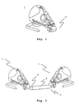
- FIG. 1 shows an example of a 3-DoF force feedback device 1. It is relatively inexpensive and it is designed for the mass-market. It has a handgrip acting as a fixation point 2, to which a three dimensional force is applied. Also, other 3-DoF devices exist.
- the handgrip 2 of each device is linked by a stylus 3. This way the stylus 3 is manipulated along three perpendicular axes and rotated around two of these axes.
- a method for automatically generating force feedback data for a haptic device By providing force feedback a six degrees of freedom movement is simulated.
- a first step consists of determining a three dimensional acceleration component corresponding to the movement to be simulated.
- a second step consists of determining a three dimensional angular velocity component corresponding to the movement to be simulated.
- a third step consists of determining control signals for controlling at least three force feedback devices.
- Each of the three force feedback devices has a fixation point associated to it and provides force effects along three perpendicular axes to its fixation point.
- the three force feedback devices are arranged at defined positions with regard to each other and the three fixation points define a geometric plane.
- fixation points are arranged in a coplanar way but do not lie on a straight line.
- the method according to the invention has the advantage that a six degrees of freedom movement is simulated with low cost equipment. Three degrees of freedom force feedback devices are available in the consumer electronic market and are available for these application at reasonable prices.
- three dimensional displacement of each fixation point depending on the three dimensional acceleration component and the three dimensional angular velocity is determined and is a basis for determining control signals for controlling the at least three force feedback devices.
- a scaling factor is determined.
- the scaling factor is used for scaling the three dimensional displacement such that the workspace of the force feedback devices is well utilized.
- the scaling factor is determined after three dimensional displacement values have been determined, which are applicable for a full sequence to be simulated. Thus, the maximum displacement for this full sequence is known and the scaling factor is determined such that the workspace is fully used in at least one dimension of the force feedback devices.
- Another solution is to adapt the scaling factor continuously to the three dimensional displacement. This is done by integration of the three dimensional displacement over a certain time. Other rules for scaling to optimally use the three dimensional workspace of the force feedback devices and at the same time to preserve the ratio between the determined displacements in different directions and for different force feedback devices are applicable.
- the force feedback devices are located in the left armrest, the right armrest and the headrest of a chair, respectively.
- the three dimensional displacements of the three fixation points are determined by the assumption that the fixation points are located in the left armrest, the right armrest and the headrest of a chair, respectively.
- the defined fixation points thus provide the illusion of a six degrees of freedom movement to a user who contacts with his left arm, right arm and head one of the fixation points, respectively.
- the three dimensional displacement of each fixation point is based on a skeleton model.
- the movement to be simulated is based on at least part of a movie or gaming content. This has the advantage that a user sitting on a chair in front of a TV or computer gets the illusion of six degrees of freedom movement synchronized to the audiovisual content he is seeing by a cheap and handy device which can be easily used as home equipment.
- a device for rendering six degrees of freedom interactions consists of at least three force feedback devices.
- Each of the three force feedback devices provides force effects to a fixation point along three perpendicular axes.
- the three force feedback devices are arranged at defined positions with regard to each other and the three fixation points define a geometric plane.
- the fixation points are arranged in a coplanar way but do not lie on a straight line.
- the defined positions of the force feedback devices being fixed positions.
- the defined positions of the force feedback devices might also move over time, such that the displacement of the fixation point is a superimposed movement of the displacement of the force feedback device and the displacement of the fixation point with regard to the force feedback device.
- fixation points being arranged such that a user stands with each of his feet on one fixation point and e.g. leans against the third fixation point. Any other arrangement in which the three fixation points have contact to a user and define a geometric plane is applicable.
- the device is integrated into a chair and one of the force feedback devices is integrated into the left armrest, the right armrest and the headrest, respectively.
- At least one further force feedback device is integrated into at least one legrest. This does not provide a further degree of freedom but supports the artificial six degrees of freedom simulation provided to the user. In this way all the remote parts of the human body are stimulated with the artificial movement while the main part of the body still does not move.
- the device includes a control unit that generates control signals to control the at least three force feedback devices dependent on each other in a way that the movements of the fixation points of the at least three force feedback devices provide six degrees of freedom movement to an object fixed between the three fixation points.
- the object fixed between the three fixation points might be any object and especially might also be a human being.
- further force feedback devices might be used to increase the number of fixation points and thus to enhance the illusion of six degrees of freedom movement.
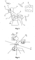
- Fig. 3 shows an exemplary embodiment of the invention.
- a user sits on a chair 7 and has contact to a fixation point 2 of a 3-DoF force feedback device H with his head/neck 3, and two further 3-DoF force feedback devices RA, LA with his left arm and his right arm 5, respectively.
- a fixation point 2 of a 3-DoF force feedback device H with his head/neck 3, and two further 3-DoF force feedback devices RA, LA with his left arm and his right arm 5, respectively.
- the arms 5 of the user lie on armrests 4, which transmit the movement of the fixation points 2 of the force feedback devices RA, LA to the users arms 5.
- the arms 5 of the user might contact the fixation points 2 directly.
- the force feedback device H which moves the head 3 of the user is mounted to the chair 7 by a fixture 8.
- the embodiment makes use of three 3-DoF local actuators to render a 6-DoF global motion (3 x 3-DoF ⁇ 6-DoF).
- a display screen 6 is arranged on which audiovisual content is presented.
- Fig. 3 shows specific examples of the movements of the fixation points 2 of the force feedback devices H, RA, LA.
- the movement of the fixation point 2 of the force feedback device H mounted at the users head is indicated by arrow 10.
- the movement of the fixation point 2 of the force feedback device RA mounted in the right armrest 4 is indicated by arrow 11.
- the 6-DoF illusion of motion which is generated is indicated by the curved arrow 9.
- Fig. 4 introduces a schematic representation of the system as well as an introduction to the different notations that are used in the following.
- the system is made of three local 3-DoF force feedback devices H, RA, LA respectively placed behind the head of the user and under the right and left forearms of the user.
- the force feedback devices H, RA, LA are preferably placed in the headrest, left armrest and right armrest of a chair (not shown here).
- the user passively rests its head and hands (or arms) on each of the 3-DoF force feedback devices H, RA, LA, while he is watching a movie projected on the display screen placed in front of him. If no motion is rendered, the three force feedback devices H, RA, LA maintain the head, right arm and left arm of the user at the central positions G H , G RA , G LA , respectively.
- each force feedback device H, RA, LA superimposes 3-DoF motions of the different associated part of the body in a limited workspace schematically indicated by the three boxes shown in Fig. 4 .
- the workspace corresponds to the maximum amplitude L of the 3-DoF force feedback device H, RA, LA in each direction.
- the proposed system aims at making the audience member feel a global 6-DoF motion.
- the 6-DoF global motion is modelled by the quantities a (t) and w (t).
- each force feedback device H, RA, LA moves in a synchronized way to give the illusion of the global motion represented by a(t) and w(t). More precisely, each force feedback device H, RA, LA renders the motions that would be felt in different parts of the body. A first force feedback device H would especially render the motion felt at the head position, whereas two other force feedback devices RA, LA render the motions felt by the hands.
- Fig. 5 discloses a generalized poly-articulated skeleton, made of body segments and joints, which is used to calculate the propagation of forces to the desired body parts. In the case described above, it targets the hands/arms and the head. If additional actuators are considered, this generalized skeleton directly allows to take them into account.
- a first simplified implementation of the skeleton is considered through a rigid body approach, where the motions of the hands are considered equivalent to the movements of the shoulders.
- the upper part of the body including the head and the chest, is considered as a turning rigid body which angular velocity (or turn-rate) is represented by the tridimensional vector w (t) and which acceleration expressed in G is a (t). Both quantities are considered to be relative to the navigation frame F N and are expressed in the body frame F B (centered in G).
- the coordinates of the head P H , and the coordinates of the left and right shoulders P LS , P RS are known in F B .
- the accelerations in each of those points are computed by the following mechanical relation (time derivation of the kinetic torsor) : a ⁇ P ⁇ S
- F N a P ⁇ S
- Determining those scaling factors is made by a preprocessing step consisting in finding the maximum amplitude of each acceleration rendered by the three different actuators. Thereby, the maximum amplitude of a full sequence is considered.
- the scaling factor is adapted continuously to the three dimensional displacement. This is done by integration of the three dimensional displacement over a certain time.
- Fig. 6 shows a schematic view of the system according to the invention.
- Motion data are extracted from the audiovisual content.
- a model is generated.
- the haptic effects are rendered and control signals to control the force feedback devices are determined.
- a system according to Fig. 4 is controlled by these control signals and a user watching audiovisual content in front of a TV screen is penetrated by the three force feedback devices.
Landscapes
- Engineering & Computer Science (AREA)
- Theoretical Computer Science (AREA)
- Business, Economics & Management (AREA)
- Physics & Mathematics (AREA)
- Educational Administration (AREA)
- Educational Technology (AREA)
- General Physics & Mathematics (AREA)
- User Interface Of Digital Computer (AREA)
Abstract
The present invention relates to a method and device for automatically generating force feedback data for a haptic device for providing simulated six degrees of freedom movement. A three dimensional acceleration component corresponding to the movement to be simulated is determined. A three dimensional angular velocity component corresponding to the movement to be simulated is determined. Control signals for controlling at least three force feedback devices are determined, wherein each of the three force feedback devices provides force effects along three perpendicular axes to a fixation point associated to each of it, the three force feedback devices being arranged at defined positions with regard to each other, and the three fixation points define a geometric plane.
Description
- The present invention relates to a method and device for automatically generating force feedback data for a haptic device for providing simulated six degrees of freedom (6-DoF) movement.
- Motion simulators are well-known devices designed to make an audience member feel motion. They are intensively used as driving or flight simulators for learning purposes. Most of them are based on the Stewart's platform (B. Dasgupta, "The Stewart platform manipulator: a review", Mechanism and Machine Theory, Vol. 35, ). It is a six degrees of freedom (6-DoF) platform moving thanks to six hydraulic cylinders. A six degrees of freedom platform moves in three directions, e.g. in two directions in the horizontal plane and in a movement direction along the vertical axis. Further, rotation around these three directions is performed. A motion simulator is basically a seat attached on this kind of platform that may be especially used to enhance audiovisual experience. Here, the seat moves while the audience member is watching a movie to enhance his experience. These systems are intensively used in amusement park or in "4D cinemas", but few of them are designed for the end-user consumer.
- Also comfortable chairs placed on four actuators dedicated to the end-user living-room are known in the art. These seats allow three degrees of freedom (pitch, roll and heave) for audiovisual content viewing and consumer applications. The three degrees of freedom are movement along the vertical axis (heave) and rotation around two perpendicular horizontal axes (pitch and roll). But these chairs remain expensive, render only 3-DoF and are still based on a Stewart's platform.
- In a less invasive way, the sensation of motion may also be induced by a force feedback device, as disclosed in
W02011/032937 . By applying a force on the user's hand, the system generates an illusion of motion with force feedback. While the interface is pulling the hand, the user feels moving forward. - A lot of force feedback devices have been proposed to enable local interaction with a user. Typically, 3-DoF force feedback devices are able to provide force effects along three perpendicular axes.
Fig. 1 shows an example of a 3-DoFforce feedback device 1. It is relatively inexpensive and it is designed for the mass-market. It has a handgrip acting as afixation point 2, to which a three dimensional force is applied. Also, other 3-DoF devices exist. - A. Shah, S. Teuscher, E. McClain, and J. Abbott, "How to build an inexpensive 5-DOF haptic device using two novint falcons," Haptics: Generating and Perceiving Tangible Sensations, pp. 136-143, 2010, disclose two 3-DoF
force feedback devices 1, which are connected to each other to provide one 5-DoF force feedback system as disclosed inFig. 2 . Thehandgrip 2 of each device is linked by astylus 3. This way thestylus 3 is manipulated along three perpendicular axes and rotated around two of these axes. - It is an object of the invention to propose a low cost device and a method for operating the same for rendering 6-DoF interactions.
- According to the invention, a method for automatically generating force feedback data for a haptic device is disclosed. By providing force feedback a six degrees of freedom movement is simulated. A first step consists of determining a three dimensional acceleration component corresponding to the movement to be simulated. A second step consists of determining a three dimensional angular velocity component corresponding to the movement to be simulated. A third step consists of determining control signals for controlling at least three force feedback devices. Each of the three force feedback devices has a fixation point associated to it and provides force effects along three perpendicular axes to its fixation point. The three force feedback devices are arranged at defined positions with regard to each other and the three fixation points define a geometric plane. Thus, the fixation points are arranged in a coplanar way but do not lie on a straight line. The method according to the invention has the advantage that a six degrees of freedom movement is simulated with low cost equipment. Three degrees of freedom force feedback devices are available in the consumer electronic market and are available for these application at reasonable prices.
- Preferably, three dimensional displacement of each fixation point depending on the three dimensional acceleration component and the three dimensional angular velocity is determined and is a basis for determining control signals for controlling the at least three force feedback devices. This has the advantage that an angular movement is simulated using devices that as standalone devices are only able to provide three dimensional movements.
- Advantageously, a scaling factor is determined. The scaling factor is used for scaling the three dimensional displacement such that the workspace of the force feedback devices is well utilized. The scaling factor is determined after three dimensional displacement values have been determined, which are applicable for a full sequence to be simulated. Thus, the maximum displacement for this full sequence is known and the scaling factor is determined such that the workspace is fully used in at least one dimension of the force feedback devices. Another solution is to adapt the scaling factor continuously to the three dimensional displacement. This is done by integration of the three dimensional displacement over a certain time. Other rules for scaling to optimally use the three dimensional workspace of the force feedback devices and at the same time to preserve the ratio between the determined displacements in different directions and for different force feedback devices are applicable.
- Advantageously, the force feedback devices are located in the left armrest, the right armrest and the headrest of a chair, respectively. Thus, the three dimensional displacements of the three fixation points are determined by the assumption that the fixation points are located in the left armrest, the right armrest and the headrest of a chair, respectively. The defined fixation points thus provide the illusion of a six degrees of freedom movement to a user who contacts with his left arm, right arm and head one of the fixation points, respectively.
- Advantageously, the three dimensional displacement of each fixation point is based on a skeleton model. Further, the movement to be simulated is based on at least part of a movie or gaming content. This has the advantage that a user sitting on a chair in front of a TV or computer gets the illusion of six degrees of freedom movement synchronized to the audiovisual content he is seeing by a cheap and handy device which can be easily used as home equipment.
- According to a further aspect of the invention, a device for rendering six degrees of freedom interactions is disclosed. The device consists of at least three force feedback devices. Each of the three force feedback devices provides force effects to a fixation point along three perpendicular axes. The three force feedback devices are arranged at defined positions with regard to each other and the three fixation points define a geometric plane. Thus, the fixation points are arranged in a coplanar way but do not lie on a straight line. The defined positions of the force feedback devices being fixed positions. Alternatively, the defined positions of the force feedback devices might also move over time, such that the displacement of the fixation point is a superimposed movement of the displacement of the force feedback device and the displacement of the fixation point with regard to the force feedback device. Further, the fixation points being arranged such that a user stands with each of his feet on one fixation point and e.g. leans against the third fixation point. Any other arrangement in which the three fixation points have contact to a user and define a geometric plane is applicable.
- Advantageously, the device is integrated into a chair and one of the force feedback devices is integrated into the left armrest, the right armrest and the headrest, respectively.
- Advantageously, at least one further force feedback device is integrated into at least one legrest. This does not provide a further degree of freedom but supports the artificial six degrees of freedom simulation provided to the user. In this way all the remote parts of the human body are stimulated with the artificial movement while the main part of the body still does not move. The inventors found that, contrary to known 6-DoF simulators, it is not necessary to move the whole body in order to generate a 6-DoF feeling in a user, but that moving at least 3 remote parts of the body is sufficient for this purpose.
- Advantageously, the device includes a control unit that generates control signals to control the at least three force feedback devices dependent on each other in a way that the movements of the fixation points of the at least three force feedback devices provide six degrees of freedom movement to an object fixed between the three fixation points. The object fixed between the three fixation points might be any object and especially might also be a human being. Also, further force feedback devices might be used to increase the number of fixation points and thus to enhance the illusion of six degrees of freedom movement.
- For better understanding the invention shall now be explained in more detail in the following description with reference to the figures. It is understood that the invention is not limited to this exemplary embodiment and that specified features can also expediently be combined and/or modified without departing from the scope of the present invention.
- Fig. 1
- shows a 3-DoF force feedback device
- Fig. 2
- shows a 5-DoF force feedback system built by two 3-DoF devices
- Fig. 3
- shows a 6-DoF force feedback system according to the invention
- Fig. 4
- shows a schematic view on the 6-DoF force feedback system according to the invention
- Fig. 5
- shows a skeleton model
- Fig. 6
- shows a schematic view of the system according to the invention including the extraction of motion data, haptic rendering and force feedback system
-
Fig. 1 and Fig. 2 are already described in the introduction above. -
Fig. 3 shows an exemplary embodiment of the invention. A user sits on achair 7 and has contact to afixation point 2 of a 3-DoF force feedback device H with his head/neck 3, and two further 3-DoF force feedback devices RA, LA with his left arm and hisright arm 5, respectively. InFig. 3 , only theright arm 5 of the user and the right armrest 4 of the chair is shown for sake of simplicity. Thearms 5 of the user lie on armrests 4, which transmit the movement of the fixation points 2 of the force feedback devices RA, LA to theusers arms 5. Alternatively, thearms 5 of the user might contact the fixation points 2 directly. The force feedback device H which moves thehead 3 of the user is mounted to thechair 7 by afixture 8. Thus, the embodiment makes use of three 3-DoF local actuators to render a 6-DoF global motion (3 x 3-DoF → 6-DoF). In front of the user, adisplay screen 6 is arranged on which audiovisual content is presented.Fig. 3 shows specific examples of the movements of the fixation points 2 of the force feedback devices H, RA, LA. The movement of thefixation point 2 of the force feedback device H mounted at the users head is indicated byarrow 10. The movement of thefixation point 2 of the force feedback device RA mounted in the right armrest 4 is indicated byarrow 11. The 6-DoF illusion of motion which is generated is indicated by the curved arrow 9. -
Fig. 4 introduces a schematic representation of the system as well as an introduction to the different notations that are used in the following. - The system is made of three local 3-DoF force feedback devices H, RA, LA respectively placed behind the head of the user and under the right and left forearms of the user. The force feedback devices H, RA, LA are preferably placed in the headrest, left armrest and right armrest of a chair (not shown here). The user passively rests its head and hands (or arms) on each of the 3-DoF force feedback devices H, RA, LA, while he is watching a movie projected on the display screen placed in front of him. If no motion is rendered, the three force feedback devices H, RA, LA maintain the head, right arm and left arm of the user at the central positions GH, GRA, GLA, respectively. After the viewing sequence has started and motion is rendered, each force feedback device H, RA, LA superimposes 3-DoF motions of the different associated part of the body in a limited workspace schematically indicated by the three boxes shown in
Fig. 4 . The workspace corresponds to the maximum amplitude L of the 3-DoF force feedback device H, RA, LA in each direction. - The proposed system aims at making the audience member feel a global 6-DoF motion. An audiovisual content augmented with some extra information concerning the main motion observed in a scene is described in terms of linear accelerations a(t) = [ax(t), ay(t), az(t)]T (the gravity component being removed) and angular velocity w(t) = [wx(t), wy(t), wz(t)]T for each time t. The 6-DoF global motion is modelled by the quantities a(t) and w(t).
- While the user is watching the audiovisual content, the three local force feedback devices H, RA, LA move in a synchronized way to give the illusion of the global motion represented by a(t) and w(t). More precisely, each force feedback device H, RA, LA renders the motions that would be felt in different parts of the body. A first force feedback device H would especially render the motion felt at the head position, whereas two other force feedback devices RA, LA render the motions felt by the hands.
-
Fig. 5 discloses a generalized poly-articulated skeleton, made of body segments and joints, which is used to calculate the propagation of forces to the desired body parts. In the case described above, it targets the hands/arms and the head. If additional actuators are considered, this generalized skeleton directly allows to take them into account. - A first simplified implementation of the skeleton is considered through a rigid body approach, where the motions of the hands are considered equivalent to the movements of the shoulders.
- The upper part of the body, including the head and the chest, is considered as a turning rigid body which angular velocity (or turn-rate) is represented by the tridimensional vector w(t) and which acceleration expressed in G is a(t). Both quantities are considered to be relative to the navigation frame FN and are expressed in the body frame FB (centered in G).
- The coordinates of the head PH, and the coordinates of the left and right shoulders PLS, PRS are known in FB. The accelerations in each of those points are computed by the following mechanical relation (time derivation of the kinetic torsor) :

- The command law to control the three local actuators is then formulated in terms of displacement from their initial and central position GH, GLA, GRA by:



where G'H, G'LA and G'RA are the new application points at instant t, and kx, ky, kz are scaling factors to map the true motions in the workspaces of the three actuators. - Those scaling factors are determined to use the workspace of each force feedback device H, RA, LA in an optimum way, by especially finding a compromise to avoid any saturation while using the biggest space available in each workspace (to have a larger amplitude in the final rendering and thus larger feelings for the user).
- Determining those scaling factors is made by a preprocessing step consisting in finding the maximum amplitude of each acceleration rendered by the three different actuators. Thereby, the maximum amplitude of a full sequence is considered. Alternatively, the scaling factor is adapted continuously to the three dimensional displacement. This is done by integration of the three dimensional displacement over a certain time.
-
Fig. 6 shows a schematic view of the system according to the invention. Motion data are extracted from the audiovisual content. A model is generated. The haptic effects are rendered and control signals to control the force feedback devices are determined. A system according toFig. 4 is controlled by these control signals and a user watching audiovisual content in front of a TV screen is penetrated by the three force feedback devices.
Claims (10)
- Method for automatically generating force feedback data for a haptic device, the force feedback providing simulated six degrees of freedom movement, characterized in that the method comprises the steps:- determining a three dimensional acceleration component corresponding to the movement to be simulated;- determining a three dimensional angular velocity component corresponding to the movement to be simulated;- determining control signals for controlling at least three force feedback devices (H, RA, LA), wherein each of the three force feedback devices (H, RA, LA) provides force effects (10, 11) along three perpendicular axes to a fixation point (2) associated to each of it, the three force feedback devices (H, RA, LA) being arranged at defined positions with regard to each other, and the three fixation points define a geometric plane.
- Method according to claim 1, characterized in that the step of determining control signals for controlling the at least three force feedback devices further comprises the step:- determining three dimensional displacement of each fixation point depending on the three dimensional acceleration component and the three dimensional angular velocity.
- Method according to claim 2, characterized in that the step of determining three dimensional displacement of each fixation point further comprises the step:- applying a scaling factor to scale the three dimensional displacements to be determined such that the workspace of the force feedback devices (H, RA, LA) is well utilized.
- Method according to any of claims 1-3, characterized in that the three dimensional displacements of the three fixation points (2) are determined under the assumption that the fixation points (2) are located in the left armrest, the right armrest (4) and the headrest of a chair (7), respectively.
- Method according to any of claims 1-4, characterized by the step of determining three dimensional displacement of each fixation point (2) is based on a skeleton model.
- Method according to any of claims 1-5, characterized by the movement to be simulated being based on at least part of a movie or gaming content.
- Device for rendering six degrees of freedom interactions, characterized in that the device consists of at least three force feedback devices (H, RA, LA), wherein each of the three force feedback devices (H, RA, LA) provides force effects to a fixation point (2) along three perpendicular axes and the three force feedback devices (H, RA, LA) are arranged at defined positions with regard to each other, and the three fixation points (H, RA, LA) define a geometric plane.
- Device according to claim 7, characterized in that the device is integrated into a chair (7) and one of the force feedback devices (H, RA, LA) is integrated into the left armrest, the right armrest (4) and the headrest, respectively.
- Device according to claim 8, characterized in that at least one further force feedback device is integrated into at least one legrest.
- Device according to any of claims 8 to 9, characterized in that it includes a control unit that generates control signals to control the at least three force feedback devices (H, RA, LA) dependent on each other in a way that the movements of the fixation points (2) of the at least three force feedback devices (H, RA, LA) provide six degrees of freedom movement (9) to an object fixed between the three fixation points (2).
Priority Applications (7)
| Application Number | Priority Date | Filing Date | Title |
|---|---|---|---|
| EP12305831.5A EP2685443A1 (en) | 2012-07-11 | 2012-07-11 | Method to render global 6 DoF motion effect with multiple local force-feedback |
| US14/391,496 US9717997B2 (en) | 2012-04-13 | 2013-04-10 | Method to render global 5 DoF motion effect with multiple local force-feedback |
| CN201380019730.XA CN104272365B (en) | 2012-04-13 | 2013-04-10 | Use the method that many local force feedback provides 6 degree of freedom movement effects of the overall situation |
| PCT/EP2013/057443 WO2013153086A1 (en) | 2012-04-13 | 2013-04-10 | Method to render global 6 dof motion effect with multiple local force-feedback |
| KR1020147028570A KR20150001752A (en) | 2012-04-13 | 2013-04-10 | Method to render global 6 dof motion effect with multiple local force-feedback |
| EP13717007.2A EP2836991A1 (en) | 2012-04-13 | 2013-04-10 | Method to render global 6 dof motion effect with multiple local force-feedback |
| JP2015504935A JP6005254B2 (en) | 2012-04-13 | 2013-04-10 | A method of providing a global 6-DOF motion effect using multiple local force feedback |
Applications Claiming Priority (1)
| Application Number | Priority Date | Filing Date | Title |
|---|---|---|---|
| EP12305831.5A EP2685443A1 (en) | 2012-07-11 | 2012-07-11 | Method to render global 6 DoF motion effect with multiple local force-feedback |
Publications (1)
| Publication Number | Publication Date |
|---|---|
| EP2685443A1 true EP2685443A1 (en) | 2014-01-15 |
Family
ID=46851902
Family Applications (1)
| Application Number | Title | Priority Date | Filing Date |
|---|---|---|---|
| EP12305831.5A Withdrawn EP2685443A1 (en) | 2012-04-13 | 2012-07-11 | Method to render global 6 DoF motion effect with multiple local force-feedback |
Country Status (1)
| Country | Link |
|---|---|
| EP (1) | EP2685443A1 (en) |
Cited By (1)
| Publication number | Priority date | Publication date | Assignee | Title |
|---|---|---|---|---|
| US9179854B2 (en) | 2005-05-16 | 2015-11-10 | Mark S. Doidge | Three-dimensional localization, display, recording, and analysis of electrical activity in the cerebral cortex |
Citations (1)
| Publication number | Priority date | Publication date | Assignee | Title |
|---|---|---|---|---|
| WO2011032937A2 (en) | 2009-09-17 | 2011-03-24 | Centre National De La Recherche Scientifique | Method for simulating specific movements by haptic feedback, and device implementing the method |
-
2012
- 2012-07-11 EP EP12305831.5A patent/EP2685443A1/en not_active Withdrawn
Patent Citations (1)
| Publication number | Priority date | Publication date | Assignee | Title |
|---|---|---|---|---|
| WO2011032937A2 (en) | 2009-09-17 | 2011-03-24 | Centre National De La Recherche Scientifique | Method for simulating specific movements by haptic feedback, and device implementing the method |
Non-Patent Citations (4)
| Title |
|---|
| A. SHAH; S. TEUSCHER; E. MCCLAIN; J. ABBOTT: "How to build an inexpensive 5-DOF haptic device using two novint falcons", HAPTICS: GENERATING AND PERCEIVING TANGIBLE SENSATIONS, 2010, pages 136 - 143, XP047270069, DOI: doi:10.1007/978-3-642-14064-8_21 |
| B. DASGUPTA: "The Stewart platform manipulator: a review", MECHANISM AND MACHINE THEORY, vol. 35, no. 1, January 2000 (2000-01-01), pages 15 - 40, XP002692605 * |
| B. DASGUPTA: "The Stewart platform manipulator: a review", MECHANISM AND MACHINE THEORY, vol. 35, no. 1, January 2000 (2000-01-01), pages 15 - 40, XP002692605, DOI: doi:10.1016/S0094-114X(99)00006-3 |
| ERIC R. BACHMANN, XIAOPING YUN, DOUG MCKINNEY, ROBERT B. MCGHEE, AND MICHAEL J. ZYDA: "Design and Implementation of MARG Sensors for3-DOF Orientation Measurement of Rigid Bodies", 31 December 2003 (2003-12-31), XP002692604, Retrieved from the Internet <URL:http://faculty.nps.edu/yun/pub/ICRA2003%20paper.pdf> [retrieved on 20130222] * |
Cited By (1)
| Publication number | Priority date | Publication date | Assignee | Title |
|---|---|---|---|---|
| US9179854B2 (en) | 2005-05-16 | 2015-11-10 | Mark S. Doidge | Three-dimensional localization, display, recording, and analysis of electrical activity in the cerebral cortex |
Similar Documents
| Publication | Publication Date | Title |
|---|---|---|
| Stanney et al. | Extended reality (XR) environments | |
| Biocca | Virtual reality technology: A tutorial | |
| Chung et al. | Exploring virtual worlds with head-mounted displays | |
| Mihelj et al. | Virtual reality technology and applications | |
| Burdea et al. | Multimodal virtual reality: Input‐output devices, system integration, and human factors | |
| Manetta et al. | Glossary of virtual reality terminology | |
| US5436638A (en) | Image display method and apparatus with means for yoking viewpoint orienting muscles of a user | |
| US9937421B2 (en) | Haptic chair for motion simulation | |
| Danieau et al. | HapSeat: producing motion sensation with multiple force-feedback devices embedded in a seat | |
| Handa et al. | Immersive technology–uses, challenges and opportunities | |
| Mazuryk et al. | History, applications, technology and future | |
| Stevenson et al. | Haptic workbench: A multisensory virtual environment | |
| Bubb | Why do we need digital human models? | |
| US9717997B2 (en) | Method to render global 5 DoF motion effect with multiple local force-feedback | |
| CN103218929A (en) | In-spaceport-bin navigation analogy method and system based on head-down bed resting | |
| Detlefsen | The cosmic perspective: Teaching middle-school children astronomy using ego-centric virtual reality | |
| Louison et al. | Spatialized vibrotactile feedback improves goal-directed movements in cluttered virtual environments | |
| Watanabe et al. | TORSO: Development of a telexistence visual system using a 6-dof robot head | |
| CN112379783A (en) | Virtual reality system for enhancing upper limb multidirectional movement of user immersion | |
| Horie et al. | Torsioncrowds: Multi-points twist stimulation display for large part of the body | |
| Terziman et al. | Can camera motions improve the perception of traveled distance in virtual environments? | |
| Louison et al. | Spatialized vibrotactile feedback contributes to goal-directed movements in cluttered virtual environments | |
| WO2022107294A1 (en) | Vr image space generation system | |
| Nesamalar et al. | An introduction to virtual reality techniques and its applications | |
| Wolf et al. | Visuo-haptic interaction |
Legal Events
| Date | Code | Title | Description |
|---|---|---|---|
| PUAI | Public reference made under article 153(3) epc to a published international application that has entered the european phase |
Free format text: ORIGINAL CODE: 0009012 |
|
| AK | Designated contracting states |
Kind code of ref document: A1 Designated state(s): AL AT BE BG CH CY CZ DE DK EE ES FI FR GB GR HR HU IE IS IT LI LT LU LV MC MK MT NL NO PL PT RO RS SE SI SK SM TR |
|
| AX | Request for extension of the european patent |
Extension state: BA ME |
|
| STAA | Information on the status of an ep patent application or granted ep patent |
Free format text: STATUS: THE APPLICATION IS DEEMED TO BE WITHDRAWN |
|
| 18D | Application deemed to be withdrawn |
Effective date: 20140716 |