EP2685346A2 - Hinge structure and electronic device - Google Patents
Hinge structure and electronic device Download PDFInfo
- Publication number
- EP2685346A2 EP2685346A2 EP13173843.7A EP13173843A EP2685346A2 EP 2685346 A2 EP2685346 A2 EP 2685346A2 EP 13173843 A EP13173843 A EP 13173843A EP 2685346 A2 EP2685346 A2 EP 2685346A2
- Authority
- EP
- European Patent Office
- Prior art keywords
- hinge pin
- hinge structure
- hinge
- protrusion
- protrusion portion
- Prior art date
- Legal status (The legal status is an assumption and is not a legal conclusion. Google has not performed a legal analysis and makes no representation as to the accuracy of the status listed.)
- Granted
Links
Images





Classifications
-
- H—ELECTRICITY
- H05—ELECTRIC TECHNIQUES NOT OTHERWISE PROVIDED FOR
- H05K—PRINTED CIRCUITS; CASINGS OR CONSTRUCTIONAL DETAILS OF ELECTRIC APPARATUS; MANUFACTURE OF ASSEMBLAGES OF ELECTRICAL COMPONENTS
- H05K5/00—Casings, cabinets or drawers for electric apparatus
- H05K5/02—Details
- H05K5/0217—Mechanical details of casings
- H05K5/0226—Hinges
-
- G—PHYSICS
- G06—COMPUTING OR CALCULATING; COUNTING
- G06F—ELECTRIC DIGITAL DATA PROCESSING
- G06F1/00—Details not covered by groups G06F3/00 - G06F13/00 and G06F21/00
- G06F1/16—Constructional details or arrangements
- G06F1/1613—Constructional details or arrangements for portable computers
- G06F1/1633—Constructional details or arrangements of portable computers not specific to the type of enclosures covered by groups G06F1/1615 - G06F1/1626
- G06F1/1675—Miscellaneous details related to the relative movement between the different enclosures or enclosure parts
- G06F1/1681—Details related solely to hinges
Definitions
- the invention generally relates to a hinge structure and an electronic device, and particularly to a hinge structure including a hinge pin and a hinge pin reception portion and an electronic device including the same.
- a hinge structure for pivotably connecting a plurality of housings has conventionally been employed in a foldable electronic device or the like.
- Japanese Patent Laying-Open No. 2009-36279 proposes a hinge structure pivotably connecting an upper housing and a lower housing of a foldable mobile phone to each other.
- Exemplary embodiments provide a hinge structure capable of achieving improved durability and an electronic device including the same.
- An exemplary embodiment provides a hinge structure including a hinge pin having a first member and a second member having one end surface and the other end surface provided at a distance from each other in an axial direction, having a protrusion portion provided to protrude from one end surface in the axial direction, arranged to be opposed to the first member at the other end surface, and being pivotable with respect to the first member, and a hinge pin reception portion having a recess portion fitting to a part of the second member and the protrusion portion of the hinge pin.
- the protrusion portion has a first surface portion extending in a radial direction of the second member.
- the recess portion has a second surface portion which can be engaged with the first surface portion.
- a part of the second member and the protrusion portion fit to the recess portion. Therefore, in pivoting the second member with respect to the first member, load applied to the hinge pin reception portion can be distributed to parts of the recess portion fitted to the part of the second member and the protrusion portion. By thus distributing load applied to the hinge pin reception portion, durability of the hinge structure can be improved.
- the second surface portion engaged with the first surface portion protruding from one end surface in the axial direction and extending in the radial direction of the second member can receive load during pivot of the second member with respect to the first member. Namely, since a surface of the second surface portion can receive load in a direction of pivot, load applied to the second surface portion can be distributed. By thus distributing load applied to the hinge pin reception portion, durability of the hinge structure can be improved.
- An exemplary embodiment is constructed to suppress pivot of the second member with respect to the hinge pin reception portion owing to engagement of the first and second surface portions with each other. As the first surface portion and the second surface portion are engaged with each other, pivot of the second member with respect to the hinge pin reception portion is suppressed and hence the second surface portion can receive load. Therefore, since the surface of the second surface portion can receive load in a direction of pivot, load applied to the second surface portion can be distributed.
- the first surface portion includes a right rotation abutment surface abutting to the second surface portion when the hinge pin rotates to the right around the axial direction and a left rotation abutment surface abutting to the second surface portion when the hinge pin rotates to the left around the axial direction.
- the right rotation abutment surface can distribute load applied to the hinge pin reception portion during rotation to the right and the left rotation abutment surface can distribute load applied to the hinge pin reception portion during rotation to the left. Therefore, in any of rotation to the right and rotation to the left, load applied to the hinge pin reception portion can be distributed.
- the protrusion portion is constructed such that a portion defining the right rotation abutment surface and a portion defining the left rotation abutment surface are linked to each other. Therefore, the protrusion portion can integrally be formed such that the portion defining the right rotation abutment surface and the portion defining the left rotation abutment surface are linked to each other. Thus, strength of the protrusion portion can be improved.
- the protrusion portion has a shape asymmetric with respect to a center of one end surface. Therefore, even when load is different depending on a direction of pivot, the protrusion portion can be formed in accordance with load.
- the recess portion is provided to expose a part of the protrusion portion. Therefore, engagement between the protrusion portion and the recess portion can visually be checked. Therefore, the protrusion portion and the recess portion can reliably be fitted to each other.
- An exemplary embodiment provides an electronic device including the hinge structure above, a first housing to which a hinge pin is attached, and a second housing to which a hinge pin reception portion is attached.
- an electronic device including a hinge structure capable of achieving improved durability can be provided.
- a construction of a game device in an exemplary embodiment will be described.
- a case where a hinge structure is applied to a game device will be described by way of example.
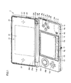
- a game device 1 is a portable game device.
- Game device 1 is constructed to be foldable.
- Game device 1 mainly has a lower housing 10, an upper housing 20, and a hinge structure 100.
- Lower housing 10 and upper housing 20 are connected to each other by means of hinge structure 100 to allow opening and closing (be foldable).
- Game device 1 is constructed to be able to be in an opened state (an open state) shown in Fig. 1 , a closed state (a closed state) shown in Fig. 2 , and a fully opened state (a full open state) shown in Fig. 3 as lower housing 10 and upper housing 20 are opened and closed by means of hinge structure 100.
- a main surface 10a of lower housing 10 and a main surface 20a of upper housing 20 are arranged with respect to each other, for example, at an angle of 155 degrees in the open state, arranged, for example, at an angle of 0 degree in the closed state, and arranged, for example, at an angle of 180 degrees in the full open state.
- Main surface 10a of lower housing 10 and main surface 20a of upper housing 20 are located on an outer side in the open state and the full open state and not located on the outer side in the closed state.
- Lower housing 10 mainly has a lower front part 11, a lower rear part 12, a lower LCD (Liquid Crystal Display) 13, a touch panel 14, a cross key 15a, an analog key 15b, operation buttons 15c to 15g, a power button 15h, a select button 15i, a home button 15j, a start button 15k, a wireless switch 16, an earphone jack 17, and LEDs 18a to 18d (Light Emitting Diodes).
- LCD Liquid Crystal Display
- Lower front part 11 forms main surface 10a and a front side surface of lower housing 10.
- Lower rear part 12 forms a back surface and a rear side surface of lower housing 10.
- On main surface 10a of lower housing 10, lower LCD 13, touch panel 14, cross key 15a, analog key 15b, operation buttons 15c to 15f, power button 15h, select button 15i, home button 15j, and start button 15k are arranged.
- Wireless switch 16 and LED 18a are arranged on a right side surface of lower housing 10, earphone jack 17 and LEDs 18b, 18c are arranged on a front surface thereof, and operation button 15g is arranged on the rear surface thereof. It is noted that LED 18d is arranged in a lower protrusion portion 11a1 of lower housing 10 which will be described later.
- lower housing 10 has a game card unit, an SD card unit, a touch pen holder, a power supply connector, a cradle connection terminal, a sound volume switch, and the like, which are not shown.
- the game card unit, the SD card unit, the touch pen holder, the power supply connector, and the cradle connection terminal are arranged in the back surface of lower housing 10, and the sound volume switch is arranged on a left side surface thereof.
- lower housing 10 contains a wireless communication module, a microphone, a battery, an information processing unit, and the like therein, which are not shown.
- Upper housing 20 mainly has an upper front part 21, an upper rear part 22, an upper LCD 23, an inner image pick-up portion 24, an outer image pick-up portion 25, a parallax amount adjustment switch 26, a sound emission hole 27, and an LED 28.
- Upper front part 21 forms main surface 20a of upper housing 20.
- Upper rear part 22 forms a back surface and a side surface of upper housing 20.
- Upper LCD 23, inner image pick-up portion 24, and sound emission hole 27 are arranged on main surface 20a of upper housing 20.
- Two outer image pick-up portions 25 and LED 28 are arranged on the back surface of upper housing 20.
- Parallax amount adjustment switch 26 is arranged at a corner portion of main surface 20a and a right side surface of upper housing 20.
- upper housing 20 contains a not-shown speaker and the like therein.
- Lower housing 10 has lower protrusion portions 11a1 and 11a2 at respective opposing end portions of an upper longer side portion, which protrude in a direction perpendicular to main surface 10a of lower housing 10.
- Lower protrusion portions 11a1 and 11a2 are provided in lower front part 11 so as to protrude in a direction opposite to lower rear part 12.
- Upper housing 20 has an upper protrusion portion 21a in a portion except for the opposing end portions of the lower longer side portion, which protrudes from a lower surface of upper housing 20 in a direction perpendicular to the lower surface.
- Upper protrusion portion 21a is provided to extend along main surface 20a of upper housing 20.
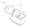
- hinge structure 100 As lower protrusion portions 11a1 and 11a2 of lower housing 10 and upper protrusion portion 21a of upper housing 20 are coupled to each other by means of hinge structure 100, lower housing 10 and upper housing 20 are connected to each other to be foldable. Hinge structure 100 shown in Fig. 4 is accommodated in the inside of lower protrusion portion 11a1 and upper protrusion portion 21a shown in Fig. 1 .
- hinge structure 100 couples lower housing 10 and upper housing 20 to each other to allow opening and closing.
- Hinge structure 100 has a hinge pin 110 and a hinge pin reception portion 120.
- Hinge pin 110 is attached to upper protrusion portion 21a of upper front part 21 of upper housing (a first housing) 20.
- Hinge pin reception portion 120 is attached to lower protrusion portion 11a1 of lower front part 11 of lower housing (a second housing) 10.
- hinge pin 110 has a first member 111 and a second member 112.
- Hinge pin 110 has a substantially columnar shape.
- Second member 112 has one end surface 112a and the other end surface 112b provided at a distance from each other in an axial direction A.
- Second member 112 has a protrusion portion 113 provided to protrude from one end surface 112a in axial direction A.
- Second member 112 is arranged to be opposed to first member 111 at the other end surface 112b.
- Second member 112 is constructed to be pivotable with respect to first member 121.
- An outer circumferential surface of hinge pin 110 has two arc portions 115 and two planar portions 11b linking two arc portions 115.
- Planar portion 116 of second member 112 is constructed such that it fits to a linear inner circumferential portion 123b which will be described later to thereby suppress pivot during pivot of second member 112.
- Hinge pin reception portion 120 has a recess portion 121 fitted to a part of second member 112 and protrusion portion 113 of hinge pin 110.
- Protrusion portion 113 has a first surface portion 114 extending in a radial direction B of second member 112. Radial direction B is a direction other than a direction of an outer circumference of second member 112.
- Recess portion 121 has a second surface portion 122 which can be engaged with first surface portion 114.
- Hinge structure 100 is constructed such that first surface portion 114 and second surface portion 122 are engaged with each other to thereby suppress pivot of second member 112 with respect to hinge pin reception portion 120.
- Recess portion 121 of hinge pin reception portion 120 has a first recess portion 123 and a second recess portion 124 communicating with first recess portion 123.
- First recess portion 123 has an arc-shaped inner circumferential portion 123a and linear inner circumferential portion 123b.
- Hinge pin reception portion 120 has a projection portion 125 where a part of recess portion 121 is provided, a stopper portion 126 arranged opposite to projection portion 125 with respect to recess portion 121, an outer wall portion 127, and a space 128 surrounded by outer wall portion 127. While hinge pin 110 is inserted in hinge pin reception portion 120, protrusion portion 113 of hinge pin 110 is exposed to space 128.
- hinge pin 110 is inserted in recess portion 121, recess portion 121 is fitted to hinge pin 110.
- the part of second member 112 and protrusion portion 113 are fitted to recess portion 121.
- a tip end portion of second member 112 is fitted to first recess portion 123, and protrusion portion 113 is fitted to second recess portion 124.
- Arc portion 115 of second member 112 is fitted to arc-shaped inner circumferential portion 123a of first recess portion 123, and planar portion 116 of second member 112 is fitted to linear inner circumferential portion 123b of first recess portion 123.
- first surface portion 114 of protrusion portion 113 has a right rotation abutment surface RS1 and a left rotation abutment surface LS1.
- second surface portion 122 of recess portion 121 has a right rotation abutment surface RS2 and a left rotation abutment surface LS2.
- Right rotation abutment surface RS1 is a surface which abuts to right rotation abutment surface RS2 when hinge pin 110 rotates to the right (rotation in a direction shown with an arrow R in Fig. 5 ) around axial direction A.
- Left rotation abutment surface LS1 is a surface which abuts to left rotation abutment surface LS2 when hinge pin 110 rotates to the left (rotation in a direction shown with an arrow L in Fig. 5 ) around axial direction A.
- Right rotation abutment surface RS1 and left rotation abutment surface LS1 are arranged in radial direction B with a center O of one end surface 112a lying therebetween.
- Right rotation abutment surface RS1 and left rotation abutment surface LS1 are not continuously formed, and lengths of surfaces abutting to right rotation abutment surface RS2 and left rotation abutment surface LS2 of second surface portion 122 respectively are small.
- wobbling at the surface abutting to second surface portion 122 can be reduced.
- Protrusion portion 113 is constructed such that a portion defining right rotation abutment surface RS1 and a portion defining left rotation abutment surface LS1 are linked to each other. Protrusion portion 113 is integrally formed. Protrusion portion 113 is formed to have a U-shape at one end surface 112a.
- Protrusion portion 113 has a shape asymmetric with respect to center O of one end surface 112a. Protrusion portion 113 is formed such that right rotation abutment surface RS1 is smaller than left rotation abutment surface LS1.
- Recess portion 121 is provided to expose a part of protrusion portion 113 of hinge pin 110 while hinge pin 110 is inserted in hinge pin reception portion 120.
- Protrusion portion 113 is formed such that a part of its side surface extends along an outer circumferential surface of second member 112.
- hinge pin 110 A construction of hinge pin 110 will be described in further detail with reference to Figs. 8 and 9 . It is noted that, for the sake of facilitated illustration, hinge pin 110 is shown in a partially simplified manner in Figs. 4 to 6 and a spring 111a, a catch 111b, and the like, which will be described next, are simplified.
- first member 111 has spring 111a and catch 111b.
- Second member 112 has a disc 112c. While a ball 30 is sandwiched between catch 111b biased by spring 111a and disc 112c, a pin 31 pivotably fixes first member 111 and second member 112.
- hinge pin reception portion 120 is inserted in an engagement recess portion 11b of lower front part 11 from a side of projection portion 125 (see Fig. 5 ). As stopper portion 126 is locked to lower front part 11, a position of hinge pin reception portion 120 is adjusted.
- hinge pin 110 is inserted in and fitted to an engagement hole 21b in upper protrusion portion 21a of upper front part 21 of upper housing 20.
- hinge pin 110 is fixed to engagement hole 21b.
- first member 111 and second member 112 of hinge pin 110 are fixed by a stopper 140.
- Hinge pin reception portion 120 is inserted in and fitted to engagement recess portion 11b of lower protrusion portion 11a1 of lower front part 11 of lower housing 10. In addition, hinge pin reception portion 120 is fixed to lower protrusion portion 11a1 by an engagement member 150. Thus, hinge pin reception portion 120 is fixed to engagement recess portion 11b.
- hinge pin 110 is fixed to engagement hole 21 b and hinge pin reception portion 120 is fixed to engagement recess portion 11b, lower housing 10 and upper housing 20 can pivot relative to each other by pivoting first member 111 of hinge pin 110 with respect to second member 112.
- hinge structure 100 pivots with respect to second member 112 fitted to hinge pin reception portion 120.
- hinge structure 100 is in a state shown in Fig. 13 .
- game device 1 makes transition from the open state to the closed state.
- hinge structure 100 is in a state shown in Fig. 14 . In this case, game device 1 makes transition from the open state to the full open state.
- First surface portion 114 and second surface portion 122 abut to each other, so that they can receive a part of load applied to hinge pin reception portion 120 while second member 112 is pivoted with respect to first member 111. More specifically, when second member 112 is pivoted with respect to first member 111, for example, in making transition to the open state and transition to the full open state, torque is applied to planar portion 116 of second member 112 and consequently load is applied to linear inner circumferential portion 123b of hinge pin reception portion 120 in contact with planar portion 116. In addition thereto, torque is applied also to an abutment surface of first surface portion 114, and second surface portion 122 in contact with the abutment surface also receives load. Thus, load applied to hinge pin reception portion 120 during pivot is distributed.
- first surface portion 114 and second surface portion 122 of the subject application abut to each other, the surface and a direction in which force is applied are perpendicular to each other. Therefore, load can be received without the force being concentrated in a specific portion of the surface.
- protrusion portion 113 is formed to have a U-shape
- a shape of protrusion portion 113 is not limited as such. Referring to Fig. 15 , in a hinge structure according to a variation, protrusion portion 113 is formed to have a semicircular shape.
- hinge structure 100 a part of second member 112 and protrusion portion 113 fit to recess portion 121. Therefore, in pivoting second member 112 with respect to first member 111, load applied to hinge pin reception portion 120 can be distributed to parts of recess portion 121 fitted to the part of second member 112 and protrusion portion 113. By thus distributing load applied to hinge pin reception portion 120, durability of hinge structure 100 can be improved.
- second surface portion 122 engaged with the first surface portion protruding from one end surface in the axial direction and extending in a radial direction of the second member can receive load during pivot of second member 112 with respect to first member 111. Namely, since a surface of second surface portion 122 can receive load in a direction of pivot, load applied to second surface portion 122 can be distributed. By thus distributing load applied to hinge pin reception portion 120, durability of hinge structure 100 can be improved.
- hinge structure 100 as first surface portion 114 and second surface portion 122 are engaged with each other, pivot of second member 112 with respect to hinge pin reception portion 120 is suppressed and hence second surface portion 122 can receive load. Therefore, since the surface of second surface portion 122 can receive load in a direction of pivot, load applied to second surface portion 122 can be distributed.
- right rotation abutment surface RS can distribute load applied to hinge pin reception portion 120 during rotation to the right and left rotation abutment surface LS can distribute load applied to hinge pin reception portion 120 during rotation to the left. Therefore, in any of rotation to the right and rotation to the left, load applied to hinge pin reception portion 120 can be distributed.
- protrusion portion 113 can integrally be formed such that the portion defining right rotation abutment surface RS and the portion defining left rotation abutment surface LS are linked to each other. Thus, strength of protrusion portion 113 can be improved.
- protrusion portion 113 has a shape asymmetric with respect to the center of one end surface 112a. Therefore, even when load is different depending on a direction of pivot, the protrusion portion can be formed in accordance with load.
- hinge structure 100 since recess portion 121 is provided to expose a part of protrusion portion 123, engagement between protrusion portion 113 and recess portion 121 can visually be checked. Therefore, protrusion portion 113 and recess portion 121 can reliably be fitted to each other.
- Game device 1 includes hinge structure 100 described above, upper housing 20 to which hinge pin 110 is attached, and lower housing 10 to which the hinge pin reception portion is attached.
- game device 1 including hinge structure 100 capable of achieving improved durability can be provided.
- the hinge structure is applicable to various electronic devices in which a plurality of housings are coupled by means of a hinge structure.
- a mobile phone, a PDA (Personal Digital Assistant), a personal computer, and the like are exemplified as the electronic devices.
Landscapes
- Engineering & Computer Science (AREA)
- Computer Hardware Design (AREA)
- Theoretical Computer Science (AREA)
- Human Computer Interaction (AREA)
- Physics & Mathematics (AREA)
- General Engineering & Computer Science (AREA)
- General Physics & Mathematics (AREA)
- Microelectronics & Electronic Packaging (AREA)
- Telephone Set Structure (AREA)
- Pivots And Pivotal Connections (AREA)
- Casings For Electric Apparatus (AREA)
Abstract
Description
- The invention generally relates to a hinge structure and an electronic device, and particularly to a hinge structure including a hinge pin and a hinge pin reception portion and an electronic device including the same.
- A hinge structure for pivotably connecting a plurality of housings has conventionally been employed in a foldable electronic device or the like. For example, Japanese Patent Laying-Open No.
2009-36279 - In the hinge structure as described in the publication above, load is applied to the hinge structure when the upper housing is opened and closed. Therefore, improvement in durability of the hinge structure is required. A problem similar to this problem may also arise in an electronic device of other types, in which a part of a housing can be opened and closed by means of a hinge structure.
- Exemplary embodiments provide a hinge structure capable of achieving improved durability and an electronic device including the same.
- An exemplary embodiment provides a hinge structure including a hinge pin having a first member and a second member having one end surface and the other end surface provided at a distance from each other in an axial direction, having a protrusion portion provided to protrude from one end surface in the axial direction, arranged to be opposed to the first member at the other end surface, and being pivotable with respect to the first member, and a hinge pin reception portion having a recess portion fitting to a part of the second member and the protrusion portion of the hinge pin. The protrusion portion has a first surface portion extending in a radial direction of the second member. The recess portion has a second surface portion which can be engaged with the first surface portion.
- According to the exemplary embodiment, a part of the second member and the protrusion portion fit to the recess portion. Therefore, in pivoting the second member with respect to the first member, load applied to the hinge pin reception portion can be distributed to parts of the recess portion fitted to the part of the second member and the protrusion portion. By thus distributing load applied to the hinge pin reception portion, durability of the hinge structure can be improved.
- In addition, the second surface portion engaged with the first surface portion protruding from one end surface in the axial direction and extending in the radial direction of the second member can receive load during pivot of the second member with respect to the first member. Namely, since a surface of the second surface portion can receive load in a direction of pivot, load applied to the second surface portion can be distributed. By thus distributing load applied to the hinge pin reception portion, durability of the hinge structure can be improved.
- An exemplary embodiment is constructed to suppress pivot of the second member with respect to the hinge pin reception portion owing to engagement of the first and second surface portions with each other. As the first surface portion and the second surface portion are engaged with each other, pivot of the second member with respect to the hinge pin reception portion is suppressed and hence the second surface portion can receive load. Therefore, since the surface of the second surface portion can receive load in a direction of pivot, load applied to the second surface portion can be distributed.
- In an exemplary embodiment, the first surface portion includes a right rotation abutment surface abutting to the second surface portion when the hinge pin rotates to the right around the axial direction and a left rotation abutment surface abutting to the second surface portion when the hinge pin rotates to the left around the axial direction. The right rotation abutment surface can distribute load applied to the hinge pin reception portion during rotation to the right and the left rotation abutment surface can distribute load applied to the hinge pin reception portion during rotation to the left. Therefore, in any of rotation to the right and rotation to the left, load applied to the hinge pin reception portion can be distributed.
- In an exemplary embodiment, the protrusion portion is constructed such that a portion defining the right rotation abutment surface and a portion defining the left rotation abutment surface are linked to each other. Therefore, the protrusion portion can integrally be formed such that the portion defining the right rotation abutment surface and the portion defining the left rotation abutment surface are linked to each other. Thus, strength of the protrusion portion can be improved.
- In an exemplary embodiment, the protrusion portion has a shape asymmetric with respect to a center of one end surface. Therefore, even when load is different depending on a direction of pivot, the protrusion portion can be formed in accordance with load.
- In an exemplary embodiment, the recess portion is provided to expose a part of the protrusion portion. Therefore, engagement between the protrusion portion and the recess portion can visually be checked. Therefore, the protrusion portion and the recess portion can reliably be fitted to each other.
- An exemplary embodiment provides an electronic device including the hinge structure above, a first housing to which a hinge pin is attached, and a second housing to which a hinge pin reception portion is attached. Thus, an electronic device including a hinge structure capable of achieving improved durability can be provided.
- The foregoing and other objects, features, aspects and advantages of the exemplary embodiments will become more apparent from the following detailed description of the exemplary embodiments when taken in conjunction with the accompanying drawings.
-
-
Figure 1 shows an exemplary illustrative non-limiting schematic perspective view showing an open state of a game device according to an exemplary embodiment. -
Figure 2 shows an exemplary illustrative non-limiting schematic perspective view showing a closed state of the game device according to an exemplary embodiment. -
Figure 3 shows an exemplary illustrative non-limiting schematic perspective view showing a full open state of the game device according to an exemplary embodiment. -
Figure 4 shows an exemplary illustrative non-limiting enlarged perspective view of a hinge structure inFig. 1 according to an exemplary embodiment, -
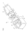
Figure 5 shows an exemplary illustrative non-limiting schematic exploded perspective view when viewed from a side of a hinge pin reception portion of the hinge structure according to an exemplary embodiment. -
Figure 6 shows an exemplary illustrative non-limiting schematic exploded perspective view when viewed from a side of a hinge pin of the hinge structure according to an exemplary embodiment. -
Figure 7 shows an exemplary illustrative non-limiting cross-sectional view along the line VII-VII inFig. 5 , showing a state that the hinge pin is inserted in the hinge pin reception portion according to an exemplary embodiment. -
Figure 8 shows an exemplary illustrative non-limiting schematic front view of the hinge pin according to an exemplary embodiment. -
Figure 9 shows an exemplary illustrative non-limiting schematic top view of the hinge pin according to an exemplary embodiment. -
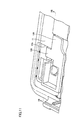
Figure 10 shows an exemplary illustrative non-limiting schematic perspective view showing a state that the hinge structure is attached to a lower front part according to an exemplary embodiment. -
Figure 11 shows an exemplary illustrative non-limiting enlarged view of a P portion inFig. 10 according to an exemplary embodiment. -
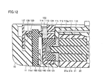
Figure 12 shows an exemplary illustrative non-limiting schematic cross-sectional view along the line XII-XII inFig. 11 according to an exemplary embodiment. -
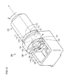
Figure 13 shows an exemplary illustrative non-limiting schematic perspective view showing a state that a first member is rotated to the right in the hinge structure according to an exemplary embodiment. -
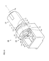
Figure 14 shows an exemplary illustrative non-limiting schematic perspective view showing a state that the first member is rotated to the left in the hinge structure according to an exemplary embodiment. -
Figure 15 shows an exemplary illustrative non-limiting schematic perspective view of a hinge structure in a variation according to an exemplary embodiment. - Exemplary embodiments will be described hereinafter with reference to the drawings.
- Initially, a construction of a game device in an exemplary embodiment will be described. In exemplary embodiments, a case where a hinge structure is applied to a game device will be described by way of example.
- Referring to
Figs. 1 to 3 , agame device 1 is a portable game device.Game device 1 is constructed to be foldable.Game device 1 mainly has alower housing 10, anupper housing 20, and ahinge structure 100.Lower housing 10 andupper housing 20 are connected to each other by means ofhinge structure 100 to allow opening and closing (be foldable). -
Game device 1 is constructed to be able to be in an opened state (an open state) shown inFig. 1 , a closed state (a closed state) shown inFig. 2 , and a fully opened state (a full open state) shown inFig. 3 aslower housing 10 andupper housing 20 are opened and closed by means ofhinge structure 100. Amain surface 10a oflower housing 10 and amain surface 20a ofupper housing 20 are arranged with respect to each other, for example, at an angle of 155 degrees in the open state, arranged, for example, at an angle of 0 degree in the closed state, and arranged, for example, at an angle of 180 degrees in the full open state.Main surface 10a oflower housing 10 andmain surface 20a ofupper housing 20 are located on an outer side in the open state and the full open state and not located on the outer side in the closed state. -
Lower housing 10 mainly has alower front part 11, a lowerrear part 12, a lower LCD (Liquid Crystal Display) 13, atouch panel 14, across key 15a, ananalog key 15b,operation buttons 15c to 15g, apower button 15h, aselect button 15i, ahome button 15j, astart button 15k, awireless switch 16, anearphone jack 17, andLEDs 18a to 18d (Light Emitting Diodes). -
Lower front part 11 formsmain surface 10a and a front side surface oflower housing 10. Lowerrear part 12 forms a back surface and a rear side surface oflower housing 10. Onmain surface 10a oflower housing 10,lower LCD 13,touch panel 14, cross key 15a, analog key 15b,operation buttons 15c to 15f,power button 15h,select button 15i,home button 15j, and startbutton 15k are arranged.Wireless switch 16 andLED 18a are arranged on a right side surface oflower housing 10,earphone jack 17 andLEDs operation button 15g is arranged on the rear surface thereof. It is noted thatLED 18d is arranged in a lower protrusion portion 11a1 oflower housing 10 which will be described later. - In addition,
lower housing 10 has a game card unit, an SD card unit, a touch pen holder, a power supply connector, a cradle connection terminal, a sound volume switch, and the like, which are not shown. The game card unit, the SD card unit, the touch pen holder, the power supply connector, and the cradle connection terminal are arranged in the back surface oflower housing 10, and the sound volume switch is arranged on a left side surface thereof. In addition,lower housing 10 contains a wireless communication module, a microphone, a battery, an information processing unit, and the like therein, which are not shown. -
Upper housing 20 mainly has an upperfront part 21, an upperrear part 22, anupper LCD 23, an inner image pick-upportion 24, an outer image pick-upportion 25, a parallaxamount adjustment switch 26, asound emission hole 27, and anLED 28. Upperfront part 21 formsmain surface 20a ofupper housing 20. Upperrear part 22 forms a back surface and a side surface ofupper housing 20. -
Upper LCD 23, inner image pick-upportion 24, andsound emission hole 27 are arranged onmain surface 20a ofupper housing 20. Two outer image pick-upportions 25 andLED 28 are arranged on the back surface ofupper housing 20. Parallaxamount adjustment switch 26 is arranged at a corner portion ofmain surface 20a and a right side surface ofupper housing 20. In addition,upper housing 20 contains a not-shown speaker and the like therein. -
Lower housing 10 has lower protrusion portions 11a1 and 11a2 at respective opposing end portions of an upper longer side portion, which protrude in a direction perpendicular tomain surface 10a oflower housing 10. Lower protrusion portions 11a1 and 11a2 are provided in lowerfront part 11 so as to protrude in a direction opposite to lowerrear part 12.Upper housing 20 has anupper protrusion portion 21a in a portion except for the opposing end portions of the lower longer side portion, which protrudes from a lower surface ofupper housing 20 in a direction perpendicular to the lower surface.Upper protrusion portion 21a is provided to extend alongmain surface 20a ofupper housing 20. - As lower protrusion portions 11a1 and 11a2 of
lower housing 10 andupper protrusion portion 21a ofupper housing 20 are coupled to each other by means ofhinge structure 100,lower housing 10 andupper housing 20 are connected to each other to be foldable.Hinge structure 100 shown inFig. 4 is accommodated in the inside of lower protrusion portion 11a1 andupper protrusion portion 21a shown inFig. 1 . - Referring to
Figs. 1 and4 , hingestructure 100 coupleslower housing 10 andupper housing 20 to each other to allow opening and closing.Hinge structure 100 has ahinge pin 110 and a hingepin reception portion 120.Hinge pin 110 is attached toupper protrusion portion 21a of upperfront part 21 of upper housing (a first housing) 20. Hingepin reception portion 120 is attached to lower protrusion portion 11a1 of lowerfront part 11 of lower housing (a second housing) 10. - Referring to
Figs. 5 and6 ,hinge pin 110 has afirst member 111 and asecond member 112.Hinge pin 110 has a substantially columnar shape.Second member 112 has oneend surface 112a and theother end surface 112b provided at a distance from each other in an axial directionA. Second member 112 has aprotrusion portion 113 provided to protrude from oneend surface 112a in axial directionA. Second member 112 is arranged to be opposed tofirst member 111 at theother end surface 112b.Second member 112 is constructed to be pivotable with respect tofirst member 121. An outer circumferential surface ofhinge pin 110 has twoarc portions 115 and twoplanar portions 11b linking twoarc portions 115. - Two
arc portions 115 and twoplanar portions 116 are formed in both offirst member 111 andsecond member 112.Planar portion 116 ofsecond member 112 is constructed such that it fits to a linear innercircumferential portion 123b which will be described later to thereby suppress pivot during pivot ofsecond member 112. - Hinge
pin reception portion 120 has arecess portion 121 fitted to a part ofsecond member 112 andprotrusion portion 113 ofhinge pin 110.Protrusion portion 113 has afirst surface portion 114 extending in a radial direction B ofsecond member 112. Radial direction B is a direction other than a direction of an outer circumference ofsecond member 112.Recess portion 121 has asecond surface portion 122 which can be engaged withfirst surface portion 114. -
Hinge structure 100 is constructed such thatfirst surface portion 114 andsecond surface portion 122 are engaged with each other to thereby suppress pivot ofsecond member 112 with respect to hingepin reception portion 120. -
Recess portion 121 of hingepin reception portion 120 has afirst recess portion 123 and asecond recess portion 124 communicating withfirst recess portion 123.First recess portion 123 has an arc-shaped innercircumferential portion 123a and linear innercircumferential portion 123b. Hingepin reception portion 120 has aprojection portion 125 where a part ofrecess portion 121 is provided, astopper portion 126 arranged opposite toprojection portion 125 with respect torecess portion 121, anouter wall portion 127, and aspace 128 surrounded byouter wall portion 127. Whilehinge pin 110 is inserted in hingepin reception portion 120,protrusion portion 113 ofhinge pin 110 is exposed tospace 128. - While
hinge pin 110 is inserted inrecess portion 121,recess portion 121 is fitted to hingepin 110. Specifically, the part ofsecond member 112 andprotrusion portion 113 are fitted to recessportion 121. A tip end portion ofsecond member 112 is fitted tofirst recess portion 123, andprotrusion portion 113 is fitted tosecond recess portion 124.Arc portion 115 ofsecond member 112 is fitted to arc-shaped innercircumferential portion 123a offirst recess portion 123, andplanar portion 116 ofsecond member 112 is fitted to linear innercircumferential portion 123b offirst recess portion 123. - Referring to
Fig. 7 ,first surface portion 114 ofprotrusion portion 113 has a right rotation abutment surface RS1 and a left rotation abutment surface LS1. In addition,second surface portion 122 ofrecess portion 121 has a right rotation abutment surface RS2 and a left rotation abutment surface LS2. Right rotation abutment surface RS1 is a surface which abuts to right rotation abutment surface RS2 whenhinge pin 110 rotates to the right (rotation in a direction shown with an arrow R inFig. 5 ) around axial direction A. Left rotation abutment surface LS1 is a surface which abuts to left rotation abutment surface LS2 whenhinge pin 110 rotates to the left (rotation in a direction shown with an arrow L inFig. 5 ) around axial direction A. - Right rotation abutment surface RS1 and left rotation abutment surface LS1 are arranged in radial direction B with a center O of one
end surface 112a lying therebetween. Right rotation abutment surface RS1 and left rotation abutment surface LS1 are not continuously formed, and lengths of surfaces abutting to right rotation abutment surface RS2 and left rotation abutment surface LS2 ofsecond surface portion 122 respectively are small. Thus, as compared with a case where right rotation abutment surface RS1 and left rotation abutment surface LS1 are linearly formed, wobbling at the surface abutting tosecond surface portion 122 can be reduced. -
Protrusion portion 113 is constructed such that a portion defining right rotation abutment surface RS1 and a portion defining left rotation abutment surface LS1 are linked to each other.Protrusion portion 113 is integrally formed.Protrusion portion 113 is formed to have a U-shape at oneend surface 112a. -
Protrusion portion 113 has a shape asymmetric with respect to center O of oneend surface 112a.Protrusion portion 113 is formed such that right rotation abutment surface RS1 is smaller than left rotation abutment surface LS1. -
Recess portion 121 is provided to expose a part ofprotrusion portion 113 ofhinge pin 110 whilehinge pin 110 is inserted in hingepin reception portion 120.Protrusion portion 113 is formed such that a part of its side surface extends along an outer circumferential surface ofsecond member 112. - A construction of
hinge pin 110 will be described in further detail with reference toFigs. 8 and 9 . It is noted that, for the sake of facilitated illustration,hinge pin 110 is shown in a partially simplified manner inFigs. 4 to 6 and aspring 111a, acatch 111b, and the like, which will be described next, are simplified. Inhinge pin 110,first member 111 hasspring 111a and catch 111b.Second member 112 has adisc 112c. While aball 30 is sandwiched betweencatch 111b biased byspring 111a anddisc 112c, apin 31 pivotably fixesfirst member 111 andsecond member 112. - In
disc 112c, three holes each capable of lockingball 30 are formed in a portion opposed to catch 111b. Asball 30 is locked in this hall, an angle of rotation offirst member 111 with respect tosecond member 112 is held. Three holes are formed in conformity with the open state, the closed state, and the full open state ofgame device 1 shown inFigs. 1 to 3 , respectively. Thus, whenhinge pin 110 is assembled inupper housing 20 andlower housing 10 andfirst member 111 is pivoted with respect tosecond member 112,upper housing 20 can be locked to lowerhousing 10 in the open state, the closed state, or the full open state ofgame device 1. - Referring to
Figs. 10 and11 , hingepin reception portion 120 is inserted in anengagement recess portion 11b of lowerfront part 11 from a side of projection portion 125 (seeFig. 5 ). Asstopper portion 126 is locked to lowerfront part 11, a position of hingepin reception portion 120 is adjusted. - Referring to
Fig. 12 ,hinge pin 110 is inserted in and fitted to an engagement hole 21b inupper protrusion portion 21a of upperfront part 21 ofupper housing 20. Thus,hinge pin 110 is fixed to engagement hole 21b. It is noted thatfirst member 111 andsecond member 112 ofhinge pin 110 are fixed by astopper 140. - Hinge
pin reception portion 120 is inserted in and fitted toengagement recess portion 11b of lower protrusion portion 11a1 of lowerfront part 11 oflower housing 10. In addition, hingepin reception portion 120 is fixed to lower protrusion portion 11a1 by anengagement member 150. Thus, hingepin reception portion 120 is fixed toengagement recess portion 11b. - Since
hinge pin 110 is fixed to engagement hole 21 b and hingepin reception portion 120 is fixed toengagement recess portion 11b,lower housing 10 andupper housing 20 can pivot relative to each other by pivotingfirst member 111 ofhinge pin 110 with respect tosecond member 112. - An operation of
hinge structure 100 andgame device 1 including the same will now be described. Referring again toFig. 5 ,first member 11 pivots with respect tosecond member 112 fitted to hingepin reception portion 120. By rotatingfirst member 111 in the direction shown with arrow R inFig. 5 , hingestructure 100 is in a state shown inFig. 13 . In this case,game device 1 makes transition from the open state to the closed state. Alternatively, by rotatingfirst member 111 in the direction shown with arrow L inFig. 5 , hingestructure 100 is in a state shown inFig. 14 . In this case,game device 1 makes transition from the open state to the full open state. -
First surface portion 114 andsecond surface portion 122 abut to each other, so that they can receive a part of load applied to hingepin reception portion 120 whilesecond member 112 is pivoted with respect tofirst member 111. More specifically, whensecond member 112 is pivoted with respect tofirst member 111, for example, in making transition to the open state and transition to the full open state, torque is applied toplanar portion 116 ofsecond member 112 and consequently load is applied to linear innercircumferential portion 123b of hingepin reception portion 120 in contact withplanar portion 116. In addition thereto, torque is applied also to an abutment surface offirst surface portion 114, andsecond surface portion 122 in contact with the abutment surface also receives load. Thus, load applied to hingepin reception portion 120 during pivot is distributed. At the surface wherefirst surface portion 114 andsecond surface portion 122 of the subject application abut to each other, the surface and a direction in which force is applied are perpendicular to each other. Therefore, load can be received without the force being concentrated in a specific portion of the surface. - Though a case where
protrusion portion 113 is formed to have a U-shape has been described above, a shape ofprotrusion portion 113 is not limited as such. Referring toFig. 15 , in a hinge structure according to a variation,protrusion portion 113 is formed to have a semicircular shape. - Functions and effects of one or more exemplary embodiments described above will now be described.
- In
hinge structure 100, a part ofsecond member 112 andprotrusion portion 113 fit to recessportion 121. Therefore, in pivotingsecond member 112 with respect tofirst member 111, load applied to hingepin reception portion 120 can be distributed to parts ofrecess portion 121 fitted to the part ofsecond member 112 andprotrusion portion 113. By thus distributing load applied to hingepin reception portion 120, durability ofhinge structure 100 can be improved. - In addition,
second surface portion 122 engaged with the first surface portion protruding from one end surface in the axial direction and extending in a radial direction of the second member can receive load during pivot ofsecond member 112 with respect tofirst member 111. Namely, since a surface ofsecond surface portion 122 can receive load in a direction of pivot, load applied tosecond surface portion 122 can be distributed. By thus distributing load applied to hingepin reception portion 120, durability ofhinge structure 100 can be improved. - In
hinge structure 100, asfirst surface portion 114 andsecond surface portion 122 are engaged with each other, pivot ofsecond member 112 with respect to hingepin reception portion 120 is suppressed and hencesecond surface portion 122 can receive load. Therefore, since the surface ofsecond surface portion 122 can receive load in a direction of pivot, load applied tosecond surface portion 122 can be distributed. - In
hinge structure 100, right rotation abutment surface RS can distribute load applied to hingepin reception portion 120 during rotation to the right and left rotation abutment surface LS can distribute load applied to hingepin reception portion 120 during rotation to the left. Therefore, in any of rotation to the right and rotation to the left, load applied to hingepin reception portion 120 can be distributed. - In
hinge structure 100,protrusion portion 113 can integrally be formed such that the portion defining right rotation abutment surface RS and the portion defining left rotation abutment surface LS are linked to each other. Thus, strength ofprotrusion portion 113 can be improved. - In
hinge structure 100,protrusion portion 113 has a shape asymmetric with respect to the center of oneend surface 112a. Therefore, even when load is different depending on a direction of pivot, the protrusion portion can be formed in accordance with load. - In
hinge structure 100, sincerecess portion 121 is provided to expose a part ofprotrusion portion 123, engagement betweenprotrusion portion 113 andrecess portion 121 can visually be checked. Therefore,protrusion portion 113 andrecess portion 121 can reliably be fitted to each other. -
Game device 1 includeshinge structure 100 described above,upper housing 20 to whichhinge pin 110 is attached, andlower housing 10 to which the hinge pin reception portion is attached. Thus,game device 1 includinghinge structure 100 capable of achieving improved durability can be provided. - The hinge structure is applicable to various electronic devices in which a plurality of housings are coupled by means of a hinge structure. For example, in addition to the game device above, a mobile phone, a PDA (Personal Digital Assistant), a personal computer, and the like are exemplified as the electronic devices.
- While certain example systems, methods, devices, and apparatuses have been described herein, it is to be understood that the appended claims are not to be limited to the systems, methods, devices, and apparatuses disclosed, but on the contrary, are intended to cover various modifications and equivalent arrangements included within the spirit and scope of the appended claims.
Claims (7)
- A hinge structure, comprising:a hinge pin having a first member and a second member having one end surface and the other end surface provided at a distance from each other in an axial direction, having a protrusion portion provided to protrude from said one end surface in said axial direction, arranged to be opposed to said first member at said the other end surface, and being pivotable with respect to said first member; anda hinge pin reception portion having a recess portion fitting to a part of said second member and said protrusion portion of said hinge pin,said protrusion portion having a first surface portion extending in a radial direction of said second member, andsaid recess portion having a second surface portion which can be engaged with said first surface portion.
- The hinge structure according to claim 1, constructed to suppress pivot of said second member with respect to said hinge pin reception portion owing to engagement of said first and second surface portions with each other.
- The hinge structure according to claim 1 or 2, wherein
said first surface portion includes a right rotation abutment surface abutting to said second surface portion when said hinge pin rotates to right around said axial direction and a left rotation abutment surface abutting to said second surface portion when said hinge pin rotates to left around said axial direction. - The hinge structure according to claim 3, wherein
said protrusion portion is constructed such that a portion defining said right rotation abutment surface and a portion defining said left rotation abutment surface are linked to each other. - The hinge structure according to any of claims 1 to 4, wherein said protrusion portion has a shape asymmetric with respect to a center of said one end surface.
- The hinge structure according to any of claims I to 5, wherein said recess portion is provided to expose a part of said protrusion portion.
- An electronic device, comprising:the hinge structure according to any of claims 1 to 6;a first housing to which said hinge pin is attached; anda second housing to which said hinge pin reception portion is attached.
Applications Claiming Priority (1)
| Application Number | Priority Date | Filing Date | Title |
|---|---|---|---|
| JP2012156547A JP6082199B2 (en) | 2012-07-12 | 2012-07-12 | Hinge structure and electronic device |
Publications (3)
| Publication Number | Publication Date |
|---|---|
| EP2685346A2 true EP2685346A2 (en) | 2014-01-15 |
| EP2685346A3 EP2685346A3 (en) | 2016-04-13 |
| EP2685346B1 EP2685346B1 (en) | 2018-09-05 |
Family
ID=48803377
Family Applications (1)
| Application Number | Title | Priority Date | Filing Date |
|---|---|---|---|
| EP13173843.7A Active EP2685346B1 (en) | 2012-07-12 | 2013-06-26 | Hinge structure and electronic device |
Country Status (3)
| Country | Link |
|---|---|
| US (1) | US9439310B2 (en) |
| EP (1) | EP2685346B1 (en) |
| JP (1) | JP6082199B2 (en) |
Families Citing this family (4)
| Publication number | Priority date | Publication date | Assignee | Title |
|---|---|---|---|---|
| JP5891991B2 (en) * | 2012-07-31 | 2016-03-23 | 富士通株式会社 | HINGE DEVICE AND ELECTRONIC DEVICE USING THE HINGE DEVICE |
| CN203814098U (en) * | 2014-05-14 | 2014-09-03 | 京东方(河北)移动显示技术有限公司 | Packaging case for electronic device |
| CN104332000B (en) * | 2014-11-27 | 2016-06-29 | 广州御银自动柜员机技术有限公司 | A kind of support arrangement supporting movement planker in automatic teller machine |
| USD830465S1 (en) | 2017-04-06 | 2018-10-09 | Nintendo Co., Ltd. | Portable computer |
Citations (1)
| Publication number | Priority date | Publication date | Assignee | Title |
|---|---|---|---|---|
| JP2009036279A (en) | 2007-08-01 | 2009-02-19 | Staf Corp | Longitudinal and lateral opening hinge devices |
Family Cites Families (26)
| Publication number | Priority date | Publication date | Assignee | Title |
|---|---|---|---|---|
| JP3076265B2 (en) * | 1997-05-30 | 2000-08-14 | 静岡日本電気株式会社 | Electronic device hinge structure |
| US5894635A (en) * | 1998-02-26 | 1999-04-20 | Lu; Sheng-Nan | Hinge device |
| JP2001355371A (en) * | 2000-06-14 | 2001-12-26 | Kato Electrical Mach Co Ltd | Small hinge device |
| JP3678649B2 (en) | 2000-12-28 | 2005-08-03 | Necアクセステクニカ株式会社 | Hinge mechanism, mobile phone, and opening / closing device |
| JP2003194044A (en) * | 2001-12-28 | 2003-07-09 | Ntn Corp | One side idle tilt hinge |
| CN1787732A (en) * | 2004-12-09 | 2006-06-14 | 深圳富泰宏精密工业有限公司 | Hinge structure |
| CN2777915Y (en) * | 2004-12-30 | 2006-05-03 | 鸿富锦精密工业(深圳)有限公司 | Hinge structure |
| CN100544563C (en) * | 2004-12-30 | 2009-09-23 | 深圳富泰宏精密工业有限公司 | hinge structure |
| CN100446645C (en) * | 2005-05-13 | 2008-12-24 | 深圳富泰宏精密工业有限公司 | Hinge structure |
| US20080066262A1 (en) * | 2005-05-25 | 2008-03-20 | Shenzhen Futaihong Precision Industry Co., Ltd. | Hinge and foldable electronics device using the hinge |
| CN1916434B (en) * | 2005-08-19 | 2010-06-02 | 深圳富泰宏精密工业有限公司 | Hinge structure, and portable electronic equipment of using the hinge structure |
| US7974666B2 (en) * | 2005-12-13 | 2011-07-05 | Panasonic Corporation | Opening/closing device and mobile device using the same |
| CN100501177C (en) * | 2006-06-23 | 2009-06-17 | 鸿富锦精密工业(深圳)有限公司 | Hinge structure, and foldaway electronic equipment using the structure |
| US20080115323A1 (en) | 2006-11-17 | 2008-05-22 | Sony Ericsson Mobile Communications Ab | Spring loaded hinge mechanism |
| US7631397B2 (en) * | 2007-09-06 | 2009-12-15 | Cheng Uei Precision Industry Co., Ltd. | Hinge |
| US7596830B2 (en) * | 2007-09-06 | 2009-10-06 | Cheng Uei Precision Industry Co., Ltd. | Hinge |
| KR100912611B1 (en) * | 2007-11-02 | 2009-08-17 | (주)엘티엠에이피 | Mobile Hinge Hinge Module |
| US7784153B2 (en) * | 2007-11-27 | 2010-08-31 | Cheng Uei Precision Industry Co., Ltd. | Hinge apparatus |
| US7743465B2 (en) * | 2007-12-17 | 2010-06-29 | Cheng Uei Precision Industry Co., Ltd | Damping hinge apparatus |
| US20090217486A1 (en) * | 2008-02-28 | 2009-09-03 | Kabushiki Kaisha Toshiba | Hinge device and electronic apparatus |
| CN101566191A (en) * | 2008-04-22 | 2009-10-28 | 深圳富泰宏精密工业有限公司 | Hinge structure and portable type electronic device applying same |
| CN201246403Y (en) * | 2008-05-30 | 2009-05-27 | 鸿富锦精密工业(深圳)有限公司 | Pivotal device |
| CN201246405Y (en) * | 2008-07-01 | 2009-05-27 | 鸿富锦精密工业(深圳)有限公司 | Hubs and Interfering Components |
| US20100319162A1 (en) * | 2009-06-18 | 2010-12-23 | Naoki Kubota | Hinge device and apparatus using the same |
| CN102454692B (en) * | 2010-10-21 | 2015-03-18 | 赛恩倍吉科技顾问(深圳)有限公司 | Hinge structure and portable electronic device using same |
| US8745820B2 (en) * | 2011-09-30 | 2014-06-10 | Itt Manufacturing Enterprises Llc | Rotary hinge with adjustable damping assembly |
-
2012
- 2012-07-12 JP JP2012156547A patent/JP6082199B2/en active Active
-
2013
- 2013-06-26 EP EP13173843.7A patent/EP2685346B1/en active Active
- 2013-06-28 US US13/930,114 patent/US9439310B2/en active Active
Patent Citations (1)
| Publication number | Priority date | Publication date | Assignee | Title |
|---|---|---|---|---|
| JP2009036279A (en) | 2007-08-01 | 2009-02-19 | Staf Corp | Longitudinal and lateral opening hinge devices |
Also Published As
| Publication number | Publication date |
|---|---|
| JP6082199B2 (en) | 2017-02-15 |
| US9439310B2 (en) | 2016-09-06 |
| EP2685346A3 (en) | 2016-04-13 |
| EP2685346B1 (en) | 2018-09-05 |
| JP2014020390A (en) | 2014-02-03 |
| US20140016250A1 (en) | 2014-01-16 |
Similar Documents
| Publication | Publication Date | Title |
|---|---|---|
| US20050221874A1 (en) | Hinge device of swing-type portable terminal | |
| EP2685346B1 (en) | Hinge structure and electronic device | |
| KR100630069B1 (en) | Swing hinge device of mobile terminal | |
| JP2009168242A (en) | Biaxial hinge and electronic equipment having the same | |
| JP2006233998A5 (en) | ||
| JP2006233998A (en) | Hinge unit of portable device and mobile phone | |
| US7844050B2 (en) | Biaxial hinge device for mobile terminal and mounting mechanism thereof | |
| JP2007113686A (en) | Portable terminal and hinge mechanism | |
| US8947875B2 (en) | Portable device | |
| EP1887763A2 (en) | Dual-axis rotation folder-type mobile communication terminal and hinge device thereof | |
| WO2011145259A1 (en) | Portable apparatus | |
| US20080034817A1 (en) | Lock module | |
| US8801050B2 (en) | Locking device for case of portable electronic device | |
| US8257852B2 (en) | Battery cover mechanism | |
| US7191491B2 (en) | Hinge connector having a shaft member of a simple structure and electronic apparatus including the hinge connector | |
| US20110047755A1 (en) | Hinge | |
| EP1755318A1 (en) | Hinge device for portable terminal | |
| JP2008303920A (en) | Hinge device for portable equipment, and portable equipment | |
| KR101744788B1 (en) | Apparatus of hinge for portable electronic equipment | |
| JP3853733B2 (en) | Foldable mobile phone | |
| WO2017047035A1 (en) | Holding structure and electric device | |
| JP4010285B2 (en) | Attachment structure of strap attachment member | |
| KR101432376B1 (en) | Biaxial hinge and electronic apparatus provided with the same | |
| JP4454676B2 (en) | Portable electronic devices | |
| JP4526083B2 (en) | Portable terminal and hinge device |
Legal Events
| Date | Code | Title | Description |
|---|---|---|---|
| PUAI | Public reference made under article 153(3) epc to a published international application that has entered the european phase |
Free format text: ORIGINAL CODE: 0009012 |
|
| AK | Designated contracting states |
Kind code of ref document: A2 Designated state(s): AL AT BE BG CH CY CZ DE DK EE ES FI FR GB GR HR HU IE IS IT LI LT LU LV MC MK MT NL NO PL PT RO RS SE SI SK SM TR |
|
| AX | Request for extension of the european patent |
Extension state: BA ME |
|
| PUAL | Search report despatched |
Free format text: ORIGINAL CODE: 0009013 |
|
| AK | Designated contracting states |
Kind code of ref document: A3 Designated state(s): AL AT BE BG CH CY CZ DE DK EE ES FI FR GB GR HR HU IE IS IT LI LT LU LV MC MK MT NL NO PL PT RO RS SE SI SK SM TR |
|
| AX | Request for extension of the european patent |
Extension state: BA ME |
|
| RIC1 | Information provided on ipc code assigned before grant |
Ipc: G06F 1/16 20060101AFI20160308BHEP |
|
| 17P | Request for examination filed |
Effective date: 20160930 |
|
| RBV | Designated contracting states (corrected) |
Designated state(s): AL AT BE BG CH CY CZ DE DK EE ES FI FR GB GR HR HU IE IS IT LI LT LU LV MC MK MT NL NO PL PT RO RS SE SI SK SM TR |
|
| GRAJ | Information related to disapproval of communication of intention to grant by the applicant or resumption of examination proceedings by the epo deleted |
Free format text: ORIGINAL CODE: EPIDOSDIGR1 |
|
| GRAP | Despatch of communication of intention to grant a patent |
Free format text: ORIGINAL CODE: EPIDOSNIGR1 |
|
| STAA | Information on the status of an ep patent application or granted ep patent |
Free format text: STATUS: REQUEST FOR EXAMINATION WAS MADE |
|
| GRAP | Despatch of communication of intention to grant a patent |
Free format text: ORIGINAL CODE: EPIDOSNIGR1 |
|
| STAA | Information on the status of an ep patent application or granted ep patent |
Free format text: STATUS: GRANT OF PATENT IS INTENDED |
|
| INTG | Intention to grant announced |
Effective date: 20180509 |
|
| RAP1 | Party data changed (applicant data changed or rights of an application transferred) |
Owner name: NINTENDO CO., LTD. |
|
| GRAS | Grant fee paid |
Free format text: ORIGINAL CODE: EPIDOSNIGR3 |
|
| GRAA | (expected) grant |
Free format text: ORIGINAL CODE: 0009210 |
|
| STAA | Information on the status of an ep patent application or granted ep patent |
Free format text: STATUS: THE PATENT HAS BEEN GRANTED |
|
| AK | Designated contracting states |
Kind code of ref document: B1 Designated state(s): AL AT BE BG CH CY CZ DE DK EE ES FI FR GB GR HR HU IE IS IT LI LT LU LV MC MK MT NL NO PL PT RO RS SE SI SK SM TR |
|
| REG | Reference to a national code |
Ref country code: GB Ref legal event code: FG4D |
|
| REG | Reference to a national code |
Ref country code: CH Ref legal event code: EP |
|
| REG | Reference to a national code |
Ref country code: AT Ref legal event code: REF Ref document number: 1038569 Country of ref document: AT Kind code of ref document: T Effective date: 20180915 |
|
| REG | Reference to a national code |
Ref country code: IE Ref legal event code: FG4D |
|
| REG | Reference to a national code |
Ref country code: DE Ref legal event code: R096 Ref document number: 602013043007 Country of ref document: DE |
|
| REG | Reference to a national code |
Ref country code: NL Ref legal event code: MP Effective date: 20180905 |
|
| REG | Reference to a national code |
Ref country code: LT Ref legal event code: MG4D |
|
| PG25 | Lapsed in a contracting state [announced via postgrant information from national office to epo] |
Ref country code: GR Free format text: LAPSE BECAUSE OF FAILURE TO SUBMIT A TRANSLATION OF THE DESCRIPTION OR TO PAY THE FEE WITHIN THE PRESCRIBED TIME-LIMIT Effective date: 20181206 Ref country code: NO Free format text: LAPSE BECAUSE OF FAILURE TO SUBMIT A TRANSLATION OF THE DESCRIPTION OR TO PAY THE FEE WITHIN THE PRESCRIBED TIME-LIMIT Effective date: 20181205 Ref country code: RS Free format text: LAPSE BECAUSE OF FAILURE TO SUBMIT A TRANSLATION OF THE DESCRIPTION OR TO PAY THE FEE WITHIN THE PRESCRIBED TIME-LIMIT Effective date: 20180905 Ref country code: SE Free format text: LAPSE BECAUSE OF FAILURE TO SUBMIT A TRANSLATION OF THE DESCRIPTION OR TO PAY THE FEE WITHIN THE PRESCRIBED TIME-LIMIT Effective date: 20180905 Ref country code: FI Free format text: LAPSE BECAUSE OF FAILURE TO SUBMIT A TRANSLATION OF THE DESCRIPTION OR TO PAY THE FEE WITHIN THE PRESCRIBED TIME-LIMIT Effective date: 20180905 Ref country code: LT Free format text: LAPSE BECAUSE OF FAILURE TO SUBMIT A TRANSLATION OF THE DESCRIPTION OR TO PAY THE FEE WITHIN THE PRESCRIBED TIME-LIMIT Effective date: 20180905 Ref country code: BG Free format text: LAPSE BECAUSE OF FAILURE TO SUBMIT A TRANSLATION OF THE DESCRIPTION OR TO PAY THE FEE WITHIN THE PRESCRIBED TIME-LIMIT Effective date: 20181205 |
|
| REG | Reference to a national code |
Ref country code: AT Ref legal event code: MK05 Ref document number: 1038569 Country of ref document: AT Kind code of ref document: T Effective date: 20180905 |
|
| PG25 | Lapsed in a contracting state [announced via postgrant information from national office to epo] |
Ref country code: LV Free format text: LAPSE BECAUSE OF FAILURE TO SUBMIT A TRANSLATION OF THE DESCRIPTION OR TO PAY THE FEE WITHIN THE PRESCRIBED TIME-LIMIT Effective date: 20180905 Ref country code: AL Free format text: LAPSE BECAUSE OF FAILURE TO SUBMIT A TRANSLATION OF THE DESCRIPTION OR TO PAY THE FEE WITHIN THE PRESCRIBED TIME-LIMIT Effective date: 20180905 Ref country code: HR Free format text: LAPSE BECAUSE OF FAILURE TO SUBMIT A TRANSLATION OF THE DESCRIPTION OR TO PAY THE FEE WITHIN THE PRESCRIBED TIME-LIMIT Effective date: 20180905 |
|
| PG25 | Lapsed in a contracting state [announced via postgrant information from national office to epo] |
Ref country code: PL Free format text: LAPSE BECAUSE OF FAILURE TO SUBMIT A TRANSLATION OF THE DESCRIPTION OR TO PAY THE FEE WITHIN THE PRESCRIBED TIME-LIMIT Effective date: 20180905 Ref country code: EE Free format text: LAPSE BECAUSE OF FAILURE TO SUBMIT A TRANSLATION OF THE DESCRIPTION OR TO PAY THE FEE WITHIN THE PRESCRIBED TIME-LIMIT Effective date: 20180905 Ref country code: AT Free format text: LAPSE BECAUSE OF FAILURE TO SUBMIT A TRANSLATION OF THE DESCRIPTION OR TO PAY THE FEE WITHIN THE PRESCRIBED TIME-LIMIT Effective date: 20180905 Ref country code: RO Free format text: LAPSE BECAUSE OF FAILURE TO SUBMIT A TRANSLATION OF THE DESCRIPTION OR TO PAY THE FEE WITHIN THE PRESCRIBED TIME-LIMIT Effective date: 20180905 Ref country code: ES Free format text: LAPSE BECAUSE OF FAILURE TO SUBMIT A TRANSLATION OF THE DESCRIPTION OR TO PAY THE FEE WITHIN THE PRESCRIBED TIME-LIMIT Effective date: 20180905 Ref country code: CZ Free format text: LAPSE BECAUSE OF FAILURE TO SUBMIT A TRANSLATION OF THE DESCRIPTION OR TO PAY THE FEE WITHIN THE PRESCRIBED TIME-LIMIT Effective date: 20180905 Ref country code: NL Free format text: LAPSE BECAUSE OF FAILURE TO SUBMIT A TRANSLATION OF THE DESCRIPTION OR TO PAY THE FEE WITHIN THE PRESCRIBED TIME-LIMIT Effective date: 20180905 Ref country code: IS Free format text: LAPSE BECAUSE OF FAILURE TO SUBMIT A TRANSLATION OF THE DESCRIPTION OR TO PAY THE FEE WITHIN THE PRESCRIBED TIME-LIMIT Effective date: 20190105 Ref country code: IT Free format text: LAPSE BECAUSE OF FAILURE TO SUBMIT A TRANSLATION OF THE DESCRIPTION OR TO PAY THE FEE WITHIN THE PRESCRIBED TIME-LIMIT Effective date: 20180905 |
|
| PG25 | Lapsed in a contracting state [announced via postgrant information from national office to epo] |
Ref country code: PT Free format text: LAPSE BECAUSE OF FAILURE TO SUBMIT A TRANSLATION OF THE DESCRIPTION OR TO PAY THE FEE WITHIN THE PRESCRIBED TIME-LIMIT Effective date: 20190105 Ref country code: SK Free format text: LAPSE BECAUSE OF FAILURE TO SUBMIT A TRANSLATION OF THE DESCRIPTION OR TO PAY THE FEE WITHIN THE PRESCRIBED TIME-LIMIT Effective date: 20180905 Ref country code: SM Free format text: LAPSE BECAUSE OF FAILURE TO SUBMIT A TRANSLATION OF THE DESCRIPTION OR TO PAY THE FEE WITHIN THE PRESCRIBED TIME-LIMIT Effective date: 20180905 |
|
| REG | Reference to a national code |
Ref country code: DE Ref legal event code: R097 Ref document number: 602013043007 Country of ref document: DE |
|
| PLBE | No opposition filed within time limit |
Free format text: ORIGINAL CODE: 0009261 |
|
| STAA | Information on the status of an ep patent application or granted ep patent |
Free format text: STATUS: NO OPPOSITION FILED WITHIN TIME LIMIT |
|
| PG25 | Lapsed in a contracting state [announced via postgrant information from national office to epo] |
Ref country code: DK Free format text: LAPSE BECAUSE OF FAILURE TO SUBMIT A TRANSLATION OF THE DESCRIPTION OR TO PAY THE FEE WITHIN THE PRESCRIBED TIME-LIMIT Effective date: 20180905 |
|
| 26N | No opposition filed |
Effective date: 20190606 |
|
| PG25 | Lapsed in a contracting state [announced via postgrant information from national office to epo] |
Ref country code: SI Free format text: LAPSE BECAUSE OF FAILURE TO SUBMIT A TRANSLATION OF THE DESCRIPTION OR TO PAY THE FEE WITHIN THE PRESCRIBED TIME-LIMIT Effective date: 20180905 |
|
| PG25 | Lapsed in a contracting state [announced via postgrant information from national office to epo] |
Ref country code: MC Free format text: LAPSE BECAUSE OF FAILURE TO SUBMIT A TRANSLATION OF THE DESCRIPTION OR TO PAY THE FEE WITHIN THE PRESCRIBED TIME-LIMIT Effective date: 20180905 |
|
| REG | Reference to a national code |
Ref country code: CH Ref legal event code: PL |
|
| REG | Reference to a national code |
Ref country code: BE Ref legal event code: MM Effective date: 20190630 |
|
| PG25 | Lapsed in a contracting state [announced via postgrant information from national office to epo] |
Ref country code: TR Free format text: LAPSE BECAUSE OF FAILURE TO SUBMIT A TRANSLATION OF THE DESCRIPTION OR TO PAY THE FEE WITHIN THE PRESCRIBED TIME-LIMIT Effective date: 20180905 |
|
| PG25 | Lapsed in a contracting state [announced via postgrant information from national office to epo] |
Ref country code: IE Free format text: LAPSE BECAUSE OF NON-PAYMENT OF DUE FEES Effective date: 20190626 |
|
| PG25 | Lapsed in a contracting state [announced via postgrant information from national office to epo] |
Ref country code: LI Free format text: LAPSE BECAUSE OF NON-PAYMENT OF DUE FEES Effective date: 20190630 Ref country code: CH Free format text: LAPSE BECAUSE OF NON-PAYMENT OF DUE FEES Effective date: 20190630 Ref country code: BE Free format text: LAPSE BECAUSE OF NON-PAYMENT OF DUE FEES Effective date: 20190630 Ref country code: LU Free format text: LAPSE BECAUSE OF NON-PAYMENT OF DUE FEES Effective date: 20190626 |
|
| PG25 | Lapsed in a contracting state [announced via postgrant information from national office to epo] |
Ref country code: CY Free format text: LAPSE BECAUSE OF FAILURE TO SUBMIT A TRANSLATION OF THE DESCRIPTION OR TO PAY THE FEE WITHIN THE PRESCRIBED TIME-LIMIT Effective date: 20180905 |
|
| PG25 | Lapsed in a contracting state [announced via postgrant information from national office to epo] |
Ref country code: HU Free format text: LAPSE BECAUSE OF FAILURE TO SUBMIT A TRANSLATION OF THE DESCRIPTION OR TO PAY THE FEE WITHIN THE PRESCRIBED TIME-LIMIT; INVALID AB INITIO Effective date: 20130626 Ref country code: MT Free format text: LAPSE BECAUSE OF FAILURE TO SUBMIT A TRANSLATION OF THE DESCRIPTION OR TO PAY THE FEE WITHIN THE PRESCRIBED TIME-LIMIT Effective date: 20180905 |
|
| PG25 | Lapsed in a contracting state [announced via postgrant information from national office to epo] |
Ref country code: MK Free format text: LAPSE BECAUSE OF FAILURE TO SUBMIT A TRANSLATION OF THE DESCRIPTION OR TO PAY THE FEE WITHIN THE PRESCRIBED TIME-LIMIT Effective date: 20180905 |
|
| P01 | Opt-out of the competence of the unified patent court (upc) registered |
Effective date: 20230428 |
|
| PGFP | Annual fee paid to national office [announced via postgrant information from national office to epo] |
Ref country code: GB Payment date: 20260511 Year of fee payment: 14 |
|
| PGFP | Annual fee paid to national office [announced via postgrant information from national office to epo] |
Ref country code: DE Payment date: 20260430 Year of fee payment: 14 |
|
| PGFP | Annual fee paid to national office [announced via postgrant information from national office to epo] |
Ref country code: FR Payment date: 20260511 Year of fee payment: 14 |