EP2685338A1 - Apparatus and method for lateral control of a host vehicle during travel in a vehicle platoon - Google Patents
Apparatus and method for lateral control of a host vehicle during travel in a vehicle platoon Download PDFInfo
- Publication number
- EP2685338A1 EP2685338A1 EP12176186.0A EP12176186A EP2685338A1 EP 2685338 A1 EP2685338 A1 EP 2685338A1 EP 12176186 A EP12176186 A EP 12176186A EP 2685338 A1 EP2685338 A1 EP 2685338A1
- Authority
- EP
- European Patent Office
- Prior art keywords
- vehicle
- platoon
- lateral
- control signal
- control
- Prior art date
- Legal status (The legal status is an assumption and is not a legal conclusion. Google has not performed a legal analysis and makes no representation as to the accuracy of the status listed.)
- Granted
Links
Images


Classifications
-
- G—PHYSICS
- G05—CONTROLLING; REGULATING
- G05D—SYSTEMS FOR CONTROLLING OR REGULATING NON-ELECTRIC VARIABLES
- G05D1/00—Control of position, course, altitude or attitude of land, water, air or space vehicles, e.g. using automatic pilots
- G05D1/02—Control of position or course in two dimensions
- G05D1/021—Control of position or course in two dimensions specially adapted to land vehicles
- G05D1/0287—Control of position or course in two dimensions specially adapted to land vehicles involving a plurality of land vehicles, e.g. fleet or convoy travelling
- G05D1/0291—Fleet control
- G05D1/0293—Convoy travelling
-
- G—PHYSICS
- G08—SIGNALLING
- G08G—TRAFFIC CONTROL SYSTEMS
- G08G1/00—Traffic control systems for road vehicles
- G08G1/22—Platooning, i.e. convoy of communicating vehicles
-
- B—PERFORMING OPERATIONS; TRANSPORTING
- B60—VEHICLES IN GENERAL
- B60W—CONJOINT CONTROL OF VEHICLE SUB-UNITS OF DIFFERENT TYPE OR DIFFERENT FUNCTION; CONTROL SYSTEMS SPECIALLY ADAPTED FOR HYBRID VEHICLES; ROAD VEHICLE DRIVE CONTROL SYSTEMS FOR PURPOSES NOT RELATED TO THE CONTROL OF A PARTICULAR SUB-UNIT
- B60W60/00—Drive control systems specially adapted for autonomous road vehicles
- B60W60/001—Planning or execution of driving tasks
-
- B—PERFORMING OPERATIONS; TRANSPORTING
- B60—VEHICLES IN GENERAL
- B60T—VEHICLE BRAKE CONTROL SYSTEMS OR PARTS THEREOF; BRAKE CONTROL SYSTEMS OR PARTS THEREOF, IN GENERAL; ARRANGEMENT OF BRAKING ELEMENTS ON VEHICLES IN GENERAL; PORTABLE DEVICES FOR PREVENTING UNWANTED MOVEMENT OF VEHICLES; VEHICLE MODIFICATIONS TO FACILITATE COOLING OF BRAKES
- B60T2201/00—Particular use of vehicle brake systems; Special systems using also the brakes; Special software modules within the brake system controller
- B60T2201/08—Lane monitoring; Lane Keeping Systems
-
- B—PERFORMING OPERATIONS; TRANSPORTING
- B60—VEHICLES IN GENERAL
- B60T—VEHICLE BRAKE CONTROL SYSTEMS OR PARTS THEREOF; BRAKE CONTROL SYSTEMS OR PARTS THEREOF, IN GENERAL; ARRANGEMENT OF BRAKING ELEMENTS ON VEHICLES IN GENERAL; PORTABLE DEVICES FOR PREVENTING UNWANTED MOVEMENT OF VEHICLES; VEHICLE MODIFICATIONS TO FACILITATE COOLING OF BRAKES
- B60T2201/00—Particular use of vehicle brake systems; Special systems using also the brakes; Special software modules within the brake system controller
- B60T2201/08—Lane monitoring; Lane Keeping Systems
- B60T2201/083—Lane monitoring; Lane Keeping Systems using active brake actuation
-
- B—PERFORMING OPERATIONS; TRANSPORTING
- B60—VEHICLES IN GENERAL
- B60T—VEHICLE BRAKE CONTROL SYSTEMS OR PARTS THEREOF; BRAKE CONTROL SYSTEMS OR PARTS THEREOF, IN GENERAL; ARRANGEMENT OF BRAKING ELEMENTS ON VEHICLES IN GENERAL; PORTABLE DEVICES FOR PREVENTING UNWANTED MOVEMENT OF VEHICLES; VEHICLE MODIFICATIONS TO FACILITATE COOLING OF BRAKES
- B60T2201/00—Particular use of vehicle brake systems; Special systems using also the brakes; Special software modules within the brake system controller
- B60T2201/08—Lane monitoring; Lane Keeping Systems
- B60T2201/087—Lane monitoring; Lane Keeping Systems using active steering actuation
-
- B—PERFORMING OPERATIONS; TRANSPORTING
- B60—VEHICLES IN GENERAL
- B60T—VEHICLE BRAKE CONTROL SYSTEMS OR PARTS THEREOF; BRAKE CONTROL SYSTEMS OR PARTS THEREOF, IN GENERAL; ARRANGEMENT OF BRAKING ELEMENTS ON VEHICLES IN GENERAL; PORTABLE DEVICES FOR PREVENTING UNWANTED MOVEMENT OF VEHICLES; VEHICLE MODIFICATIONS TO FACILITATE COOLING OF BRAKES
- B60T8/00—Arrangements for adjusting wheel-braking force to meet varying vehicular or ground-surface conditions, e.g. limiting or varying distribution of braking force
- B60T8/17—Using electrical or electronic regulation means to control braking
- B60T8/1755—Brake regulation specially adapted to control the stability of the vehicle, e.g. taking into account yaw rate or transverse acceleration in a curve
- B60T8/17557—Brake regulation specially adapted to control the stability of the vehicle, e.g. taking into account yaw rate or transverse acceleration in a curve specially adapted for lane departure prevention
-
- B—PERFORMING OPERATIONS; TRANSPORTING
- B60—VEHICLES IN GENERAL
- B60W—CONJOINT CONTROL OF VEHICLE SUB-UNITS OF DIFFERENT TYPE OR DIFFERENT FUNCTION; CONTROL SYSTEMS SPECIALLY ADAPTED FOR HYBRID VEHICLES; ROAD VEHICLE DRIVE CONTROL SYSTEMS FOR PURPOSES NOT RELATED TO THE CONTROL OF A PARTICULAR SUB-UNIT
- B60W2554/00—Input parameters relating to objects
- B60W2554/80—Spatial relation or speed relative to objects
-
- B—PERFORMING OPERATIONS; TRANSPORTING
- B60—VEHICLES IN GENERAL
- B60W—CONJOINT CONTROL OF VEHICLE SUB-UNITS OF DIFFERENT TYPE OR DIFFERENT FUNCTION; CONTROL SYSTEMS SPECIALLY ADAPTED FOR HYBRID VEHICLES; ROAD VEHICLE DRIVE CONTROL SYSTEMS FOR PURPOSES NOT RELATED TO THE CONTROL OF A PARTICULAR SUB-UNIT
- B60W30/00—Purposes of road vehicle drive control systems not related to the control of a particular sub-unit, e.g. of systems using conjoint control of vehicle sub-units
- B60W30/10—Path keeping
- B60W30/12—Lane keeping
-
- G—PHYSICS
- G05—CONTROLLING; REGULATING
- G05D—SYSTEMS FOR CONTROLLING OR REGULATING NON-ELECTRIC VARIABLES
- G05D1/00—Control of position, course, altitude or attitude of land, water, air or space vehicles, e.g. using automatic pilots
- G05D1/02—Control of position or course in two dimensions
- G05D1/021—Control of position or course in two dimensions specially adapted to land vehicles
- G05D1/0257—Control of position or course in two dimensions specially adapted to land vehicles using a radar
Definitions
- Embodiments herein relate to an apparatus and method lateral control of a host vehicle during travel in a vehicle platoon.
- the objective to achieve, for the longitudinal case, is each vehicle maintaining a safe and predetermined distance to the vehicle in front, called the leader.
- the distance would typically be dependent of velocity, since higher velocities require larger safety-distances.
- Arrangements are proposed through which a driver of a vehicle in such a platoon may allow the throttle and the brakes of the vehicle to be handled automatically.
- the objective is to follow the path of the leading vehicle and mimic its maneuvers in a stable manner. This may also be performed in an automated manner using a control algorithm. The driver may then hand over steering of the vehicle to an onboard computer.
- each vehicle will depending on its state and the state of the neighboring vehicle utilize a control strategy to follow its movements and maintain the platoon.
- the platoon can under these assumptions be seen as decentralized.
- US5781119 relates to a vehicle guiding system that enables a plurality of vehicles to run in a platoon.
- a front running vehicle detects its displacement from a magnetic nail, and calculates a steering amount to be corrected (i.e. control variables).
- the front running vehicle not only controls its own movements on the basis of the control variable data but also transmits them to a following vehicle.
- the following vehicle does not detect its displacement from the magnetic nail, but controls its steering amount on the basis of the received control variable data.
- the following vehicle includes a correcting unit for correcting the received control variable data depending upon the type of the front running vehicle and the type of the following vehicle.
- the following vehicle includes a transmitter for transmitting the corrected control variable data to further following vehicles.
- the further following vehicle simply receives the control variable data from the following vehicle, and does not calculate its own control variables.
- Each of the following vehicles is controlled on the basis of the corrected control variable data received from a vehicle ahead.
- This problem needs to be either eradicated or bounded to avoid vehicles further down the line leaving the lane.
- Embodiments herein aim to provide an apparatus for lateral control of a host vehicle during travel in a vehicle platoon.
- an apparatus for lateral control of a host vehicle during travel in a vehicle platoon comprising: means for acquiring a control signal u and a lateral error E relative to a target vehicle of a preceding vehicle travelling in the vehicle platoon; filter means for filtering the received lateral error ⁇ ; filter means for filtering the received control signal u ; and controller means for executing a control algorithm for actuating lateral control of the host vehicle.
- control signal u and a lateral error ⁇ relative to a target vehicle of a preceding vehicle travelling in the vehicle platoon and filtering of these signals provides for string stability through eradicating or bounding any problems incurred by error propagation throughout a vehicle platoon.
- the means for acquiring a control signal u and a lateral error ⁇ relative to a target vehicle of a preceding vehicle comprises one or more sensors such as radar based sensors, vision based sensors or lidar based sensors.
- the provision of means for acquiring a control signal u and a lateral error ⁇ using one or more sensors, as described for the second aspect, provides for lateral control of a host vehicle during travel in a vehicle platoon which is not dependent on any vehicle-to-vehicle communication making it completely autonomous.
- the apparatus further comprises means for relaying information on the host vehicle's control signal u and the host vehicle's lateral error ⁇ relative to the target vehicle to a following vehicle in the vehicle platoon.
- the provision of means for relaying this information to a following vehicle in the vehicle platoon, as described for the third aspect, provides for the following vehicle being able to follow the leading target vehicle of the platoon without communicating directly with that vehicle.
- the apparatus further comprises means for receiving a control signal u and a lateral error E relative to the target vehicle from a preceding vehicle travelling in the vehicle platoon.
- the provision of means for receiving this information from a preceding vehicle travelling in the vehicle platoon provides for the host vehicle being able to follow the leading target vehicle of the platoon without communicating directly with that vehicle.
- the filter means for filtering the received lateral error ⁇ relative to the target vehicle are arranged to perform filtering such that, given the host vehicles capabilities G ⁇ y and the host vehicles controller C , the lateral error ⁇ is prevented from increasing when relayed downwards in the chain of vehicles travelling in the vehicle platoon, and the filter means for filtering the received control signal u are arranged to cancel unwanted effects on the chain of the control signal u of the target vehicle, and the controller means are arranged to guarantee local stability of the immediate following of the target vehicle.
- Filtering and control as described for the fifth aspect, provides for increased string stability through eradicating or bounding any problems incurred by error propagation throughout a vehicle platoon.
- control signal u and a lateral error ⁇ relative to a target vehicle of a preceding vehicle travelling in the vehicle platoon and filtering of these signals provides for string stability through eradicating or bounding any problems incurred by error propagation throughout a vehicle platoon.
- embodiments herein seek to eradicate or bound any problems incurred by error propagation throughout a vehicle platoon in order to avoid vehicles further down the line leaving the lane. This phenomenon of error increase downstream the platoon is called string instability.
- Figure 1 illustrates the proposed concept where each vehicle will, depending on its state and the state of the neighboring vehicle, utilize a control strategy to follow its movements and maintain the platoon.
- the vehicle platoon may under these assumptions be seen as decentralized.
- Figure 1 thus illustrates a lead vehicle of the platoon L and a vehicle targeted T by a host vehicle (follower) F.
- the host vehicle F does not have any contact with the platoon leader L, but it will follow its path implicitly due to the proposed control topology. That is, the host vehicle F has contact only with the target vehicle T but will implicitly follow the path of the platoon leader L without actually needing an explicit communication with it.
- Information relating to the platoon leader L is cascaded down through the chain of the proposed control topology.
- Figure 2 schematically illustrates two vehicles in a vehicle platoon, the host vehicle F and the vehicle targeted T by the host vehicle F, and their associated orientations.
- the lateral deviation that is the following host vehicle's F lateral offset from the target vehicle's T position, can be modelled as an interaction of the two vehicles' states. For sake of simplicity consider that both vehicles maintain the same longitudinal velocity. However the conclusions hold for the general case as well.
- the relation shows that the lateral deviation changes according to the rotation of the following host vehicle F as well as the difference in the direction of motion of the two vehicles.
- ⁇ y be defined as Y L - Y T
- Y F - Y T the deviation from centre of gravity to centre of gravity
- Y F - Y T t V x ⁇ ⁇ t 0 t ⁇ ⁇ t + ⁇ t d t - V x ⁇ ⁇ t 0 t ⁇ ⁇ T t + ⁇ T t d t
- ⁇ T and ⁇ T denote the yaw- and slip-angle of the leading target vehicle T, respectively, with the assumption of the initial condition for t 0 being no lateral offset.
- the second length is from the projected point at a distance ⁇ x to the centre of gravity of the leading target vehicle T as seen in a coordinate system fixed to the host vehicle F, and can for small deviations be approximated as the look-ahead distance L , as follows.
- Y L t - Y F t L sin ⁇ t
- L the look-ahead distance L can be factored into two parts, a constant part consisting of the distance l fb from the host vehicle's F centre of gravity to the front bumper of the host vehicle F and a variable term which shall be denoted L a denoting the distance from the following host vehicle's F front bumper to the leading target vehicle's T rear bumper.
- w relates the variations induced by the motions of the leading target vehicle T; hence, seen from the perspective of the following host vehicle F, there is no control over it. Treating it as a measured disturbance, the whole system can be visualized in the block-diagram of figure 3 , where the measured output coming from the sensor is the lateral deviation.
- G ⁇ ⁇ y s e 0 + f 0 ⁇ L ⁇ s 2 + b 0 ⁇ f 0 - d 0 ⁇ e 0 + c 0 ⁇ e 0 - a 0 ⁇ f 0 ⁇ L V x ⁇ s + c 0 ⁇ e 0 - a 0 ⁇ f 0 s 4 - a 0 + d 0 V x ⁇ s 3 + a 0 ⁇ d 0 - b 0 ⁇ c 0 V x 2 + c 0 ⁇ s 2
- the varying quantities longitudinal velocity V x and the look-ahead distance L are extracted from the vehicle parameters and the remaining parameters involve quantities that are assumed not to vary at all or negligibly during manoeuvres, such as vehicle mass, cornering stiffness, various lengths, etc.
- G rb s e 0 - f 0 ⁇ l rb ⁇ s 2 + c 0 ⁇ e 0 - a 0 ⁇ f 0 ⁇ - l rb + l r ⁇ L V x ⁇ s + c 0 ⁇ e 0 - a 0 ⁇ f 0 s 4 - a 0 + d 0 V x ⁇ s 3 + a 0 ⁇ d 0 - b 0 ⁇ c 0 V x 2 + c 0 ⁇ s 2
- ⁇ i G ⁇ ⁇ y ⁇ u i - G rb ⁇ u i - 1
- the information to be relayed is that of the target vehicle's T control signal and with the addition of the target vehicle's T lateral error.
- the control topology is shown in figure 3 .
- the strategy contains a local controller C that stabilizes the system based on the error to the target vehicle's T.
- Figure 3 also illustrates the proposed communication topology where the control signal u i and the lateral error ⁇ i are the signals transmitted to the host vehicle F.
- F 1 and F 2 are filters, ⁇ is the steering angle and C the local controller.
- the communicated information is both the control signal u i and the lateral error ⁇ i .
- ⁇ i G ⁇ ⁇ y ⁇ F 1 + G rb - G ⁇ ⁇ y ⁇ F 2 ⁇ C 1 + G ⁇ ⁇ y ⁇ C ⁇ ⁇ i - 1 + F 1 ⁇ G ⁇ ⁇ y ⁇ F 2 - G rb 1 + G ⁇ ⁇ y ⁇ C ⁇ ⁇ i - 2 + F 2 ⁇ G ⁇ ⁇ y ⁇ F 2 - G rb 1 + G ⁇ ⁇ y ⁇ C ⁇ u i - 2
- L 2 -induced norm is the maximum gain of the system over all frequency ranges, that is the highest gain of the system that is obtained for an input sinus signal of any frequency. It is to note that in linear system theory any signal can be described as a combination of sinus signals, hence the generality of the result.
- This L 2 -induced gain needs to be less than 1 for each vehicle i, in order to get a string stable system. In effect this can mean that in some cases the string-stability of a platoon of infinite vehicles is lost, however the filters F 1 , F 2 , and local controller C can be designed so that the string stability is maintained for a finite number of vehicles even in case of an assumed worst case model uncertainty.
- an apparatus for lateral control of a host vehicle F during travel in a vehicle platoon comprises: means for acquiring a control signal u and a lateral error ⁇ relative to a target vehicle L of a preceding vehicle T travelling in the vehicle platoon; filter means F 1 for filtering the received lateral error ⁇ ; filter means F 2 for filtering the received control signal u ; and controller means C for executing a control algorithm for actuating lateral control of the host vehicle F.
- the means for acquiring a control signal u and a lateral error ⁇ relative to a target vehicle L of a preceding vehicle T comprises one or more sensors such as RADAR (RAdio Detection And Ranging) based sensors, vision based sensors, e.g. cameras, or LIDAR (Light Detection And Ranging) based sensors.
- RADAR Radio Detection And Ranging
- vision based sensors e.g. cameras
- LIDAR Light Detection And Ranging
- the apparatus further comprises means for relaying information on the host vehicle's F control signal u and the host vehicle's F lateral error ⁇ relative to the target vehicle L to a following vehicle F2 in the vehicle platoon.
- the apparatus further comprises means for receiving a control signal u and a lateral error ⁇ relative to the target vehicle L from a preceding vehicle T travelling in the vehicle platoon.
- the filter means F 1 for filtering the received lateral error ⁇ relative to the target vehicle L are arranged to perform filtering such that, given the host vehicles F capabilities G ⁇ y and the host vehicles F controller C, the lateral error ⁇ is prevented from increasing when relayed downwards in the chain of vehicles travelling in the vehicle platoon, and the filter means F 2 for filtering the received control signal u are arranged to cancel unwanted effects on the chain of the control signal u of the target vehicle L, and the controller means C are arranged to guarantee local stability of the immediate following of the target vehicle L as described above.
- a method for lateral control of a host vehicle during travel in a vehicle platoon comprises the steps of: acquiring a control signal u and a lateral error ⁇ relative to a target vehicle L of a preceding vehicle T travelling in the vehicle platoon; filtering the received lateral error ⁇ ; filtering the received control signal u ; executing a control algorithm for actuating lateral control of the host vehicle F.
- an automotive vehicle comprising an apparatus for lateral control of a host vehicle F during travel in a vehicle platoon as described above.
Landscapes
- Engineering & Computer Science (AREA)
- Physics & Mathematics (AREA)
- General Physics & Mathematics (AREA)
- Automation & Control Theory (AREA)
- Aviation & Aerospace Engineering (AREA)
- Radar, Positioning & Navigation (AREA)
- Remote Sensing (AREA)
- Human Computer Interaction (AREA)
- Transportation (AREA)
- Mechanical Engineering (AREA)
- Control Of Driving Devices And Active Controlling Of Vehicle (AREA)
Abstract
Description
- Embodiments herein relate to an apparatus and method lateral control of a host vehicle during travel in a vehicle platoon.
- The concept of having a vehicle platoon moving in unison, whether in longitudinal or lateral direction, is of considerable interest when seeking to decrease traffic congestion and gas consumption, improve driver comfort and safety, and limit emissions.
- In the platoon, the objective to achieve, for the longitudinal case, is each vehicle maintaining a safe and predetermined distance to the vehicle in front, called the leader. The distance would typically be dependent of velocity, since higher velocities require larger safety-distances. Arrangements are proposed through which a driver of a vehicle in such a platoon may allow the throttle and the brakes of the vehicle to be handled automatically.
- With respect to lateral control of a vehicle traveling in such a platoon the objective is to follow the path of the leading vehicle and mimic its maneuvers in a stable manner. This may also be performed in an automated manner using a control algorithm. The driver may then hand over steering of the vehicle to an onboard computer.
- However, much of the earlier research has been focused on utilization of vehicle platoons operating in specialized infrastructure, such as highways with magnets integrated into the path and used as road markings.
- Recent developments, however, are more tended toward the implementation of platoons in unmodified roads using available sensor information and communication, such as the angle and distance to a preceding vehicle, in order to determine acceleration, braking or steering of a subject vehicle.
- According to the latter concept; each vehicle will depending on its state and the state of the neighboring vehicle utilize a control strategy to follow its movements and maintain the platoon. The platoon can under these assumptions be seen as decentralized.
- One previously known example is given in
US5781119 , which relates to a vehicle guiding system that enables a plurality of vehicles to run in a platoon. When the vehicle runs in the platoon, a front running vehicle detects its displacement from a magnetic nail, and calculates a steering amount to be corrected (i.e. control variables). The front running vehicle not only controls its own movements on the basis of the control variable data but also transmits them to a following vehicle. The following vehicle does not detect its displacement from the magnetic nail, but controls its steering amount on the basis of the received control variable data. The following vehicle includes a correcting unit for correcting the received control variable data depending upon the type of the front running vehicle and the type of the following vehicle. The following vehicle includes a transmitter for transmitting the corrected control variable data to further following vehicles. The further following vehicle simply receives the control variable data from the following vehicle, and does not calculate its own control variables. Each of the following vehicles is controlled on the basis of the corrected control variable data received from a vehicle ahead. - However, an issue that may arise here is error propagation throughout the platoon. In the case of the first following car being laterally displaced relative to the leader, the displacement might be amplified to the second follower, and so on.
- This problem needs to be either eradicated or bounded to avoid vehicles further down the line leaving the lane.
- Embodiments herein aim to provide an apparatus for lateral control of a host vehicle during travel in a vehicle platoon.
- This is provided through an apparatus for lateral control of a host vehicle during travel in a vehicle platoon comprising: means for acquiring a control signal u and a lateral error E relative to a target vehicle of a preceding vehicle travelling in the vehicle platoon; filter means for filtering the received lateral error ε; filter means for filtering the received control signal u; and controller means for executing a control algorithm for actuating lateral control of the host vehicle.
- The provision of control signal u and a lateral error ε relative to a target vehicle of a preceding vehicle travelling in the vehicle platoon and filtering of these signals provides for string stability through eradicating or bounding any problems incurred by error propagation throughout a vehicle platoon.
- According to a second aspect the means for acquiring a control signal u and a lateral error ε relative to a target vehicle of a preceding vehicle comprises one or more sensors such as radar based sensors, vision based sensors or lidar based sensors.
- The provision of means for acquiring a control signal u and a lateral error ε using one or more sensors, as described for the second aspect, provides for lateral control of a host vehicle during travel in a vehicle platoon which is not dependent on any vehicle-to-vehicle communication making it completely autonomous.
- According to a third aspect the apparatus further comprises means for relaying information on the host vehicle's control signal u and the host vehicle's lateral error ε relative to the target vehicle to a following vehicle in the vehicle platoon.
- The provision of means for relaying this information to a following vehicle in the vehicle platoon, as described for the third aspect, provides for the following vehicle being able to follow the leading target vehicle of the platoon without communicating directly with that vehicle.
- According to a fourth aspect the apparatus further comprises means for receiving a control signal u and a lateral error E relative to the target vehicle from a preceding vehicle travelling in the vehicle platoon.
- The provision of means for receiving this information from a preceding vehicle travelling in the vehicle platoon, as described for the fourth aspect, provides for the host vehicle being able to follow the leading target vehicle of the platoon without communicating directly with that vehicle.
- According to a fifth aspect the filter means for filtering the received lateral error ε relative to the target vehicle are arranged to perform filtering such that, given the host vehicles capabilities G Δy and the host vehicles controller C, the lateral error ε is prevented from increasing when relayed downwards in the chain of vehicles travelling in the vehicle platoon, and the filter means for filtering the received control signal u are arranged to cancel unwanted effects on the chain of the control signal u of the target vehicle, and the controller means are arranged to guarantee local stability of the immediate following of the target vehicle.
- Filtering and control, as described for the fifth aspect, provides for increased string stability through eradicating or bounding any problems incurred by error propagation throughout a vehicle platoon.
- Further embodiments herein aim to provide a method for lateral control of a host vehicle during travel in a vehicle platoon.
- This is provided through a method comprising the steps of: acquiring a control signal u and a lateral error ε relative to a target vehicle of a preceding vehicle travelling in the vehicle platoon; filtering the received lateral error ε; filtering the received control signal u; executing a control algorithm for actuating lateral control of the host vehicle.
- The provision of control signal u and a lateral error ε relative to a target vehicle of a preceding vehicle travelling in the vehicle platoon and filtering of these signals provides for string stability through eradicating or bounding any problems incurred by error propagation throughout a vehicle platoon.
- In the following, embodiments herein will be described in greater detail by way of example only with reference to attached drawings, in which
-
Fig. 1 is a schematic illustration of a vehicle platoon performing a lane-change with the leader vehicle marked by a black roof. -
Fig. 2 is a schematic illustration of the geometric interaction of two vehicles of a vehicle platoon. -
Fig.3 is a schematic illustration of the proposed control topology. -
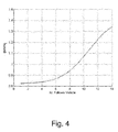
Fig. 4 shows for a numerical example the schematic illustration of the L2-induced gain for each vehicle in a platoon. - Still other objects and features of embodiments herein will become apparent from the following detailed description considered in conjunction with the accompanying drawings. It is to be understood, however, that the drawings are designed solely for purposes of illustration and not as a definition of the limits hereof, for which reference should be made to the appended claims. It should be further understood that the drawings are not necessarily drawn to scale and that, unless otherwise indicated, they are merely intended to conceptually illustrate the structures and procedures described herein.
- In overview, embodiments herein, seek to eradicate or bound any problems incurred by error propagation throughout a vehicle platoon in order to avoid vehicles further down the line leaving the lane. This phenomenon of error increase downstream the platoon is called string instability.
- In the following two important points for dealing with automated platoons are suggested; a control strategy that ensures string stability (i.e. damping the propagation of errors in the platoon), and the assumptions or infrastructures necessary to implement this control strategy.
-
Figure 1 illustrates the proposed concept where each vehicle will, depending on its state and the state of the neighboring vehicle, utilize a control strategy to follow its movements and maintain the platoon. The vehicle platoon may under these assumptions be seen as decentralized. -
Figure 1 thus illustrates a lead vehicle of the platoon L and a vehicle targeted T by a host vehicle (follower) F. The host vehicle F does not have any contact with the platoon leader L, but it will follow its path implicitly due to the proposed control topology. That is, the host vehicle F has contact only with the target vehicle T but will implicitly follow the path of the platoon leader L without actually needing an explicit communication with it. Information relating to the platoon leader L is cascaded down through the chain of the proposed control topology. -
Figure 2 schematically illustrates two vehicles in a vehicle platoon, the host vehicle F and the vehicle targeted T by the host vehicle F, and their associated orientations. With a complete dynamical model of a vehicle obtained, it is of interest to see how the system behaves in the case of the host vehicle F following a target vehicle T. For the sake of simplification, the leading target vehicle T is initially modelled as a point at distance L from the centre of gravity of the follower host vehicle F. - The lateral deviation, that is the following host vehicle's F lateral offset from the target vehicle's T position, can be modelled as an interaction of the two vehicles' states. For sake of simplicity consider that both vehicles maintain the same longitudinal velocity. However the conclusions hold for the general case as well.
- The relation shows that the lateral deviation changes according to the rotation of the following host vehicle F as well as the difference in the direction of motion of the two vehicles.
- By letting Δy be defined as YL - YT, there are two distances to consider; the first being the deviation from centre of gravity to centre of gravity, YF - YT, which is dependent on the distance travelled in the y-direction

where ψ T and β T denote the yaw- and slip-angle of the leading target vehicle T, respectively, with the assumption of the initial condition for t 0 being no lateral offset. - The second length is from the projected point at a distance Δx to the centre of gravity of the leading target vehicle T as seen in a coordinate system fixed to the host vehicle F, and can for small deviations be approximated as the look-ahead distance L, as follows.

- Thus, by approximating for small angles and adding equations (1) and (2), the following dynamic equation describing the rate of change of the lateral deviation is obtained.

- Where Vx denotes the velocity from the centre of gravity in the direction of the yaw and β is the slip-angle at the centre of gravity of the vehicle and can be approximated (for sufficiently small angles) as β = ẏ/Vx
- When augmenting the model described below with this expression while performing the substitution ẏ = Vx β as above, the following state-space formulation is obtained.

where x = [β ψ̇ ψ Δ y ]T, w = Vx (β T + ψ T ) and the state y removed since it is of no interest in this case. - In standard form, (4) can be written as

where the matrices A and B are as above and the disturbance vector w can be ignored. - If instead the point followed is on the rear bumper of the leading target vehicle T, the expression for w should be modified to

where the new term relates the orientation of followed point on the target vehicle's T rear bumper. It has to also be noted that the look-ahead distance L can be factored into two parts, a constant part consisting of the distance lfb from the host vehicle's F centre of gravity to the front bumper of the host vehicle F and a variable term which shall be denoted La denoting the distance from the following host vehicle's F front bumper to the leading target vehicle's T rear bumper. - The term w relates the variations induced by the motions of the leading target vehicle T; hence, seen from the perspective of the following host vehicle F, there is no control over it. Treating it as a measured disturbance, the whole system can be visualized in the block-diagram of
figure 3 , where the measured output coming from the sensor is the lateral deviation. - Based on the model introduced above, the transfer-function from the input to the last state is derived as

where C = [0001] since the last state is of interest, and D = 0. Therefore,
where the varying quantities longitudinal velocity Vx and the look-ahead distance L are extracted from the vehicle parameters and the remaining parameters involve quantities that are assumed not to vary at all or negligibly during manoeuvres, such as vehicle mass, cornering stiffness, various lengths, etc. - Similarly define the vehicle's transfer function Grb.

- The following notations are used in the equations above:


Where Cf denotes stiffness coefficient for front wheel and Cr for rear wheel and m denotes the mass, lf denotes length to front wheels and lr denotes length to rear wheels and Iz denotes moment of inertia, - Then the lateral deviation of the vehicle "i" to "i-1" with a simple local feedback controller C can be written as:

- In accordance with the proposed solution the information to be relayed is that of the target vehicle's T control signal and with the addition of the target vehicle's T lateral error. The control topology is shown in
figure 3 . Moreover the strategy contains a local controller C that stabilizes the system based on the error to the target vehicle's T. -
Figure 3 also illustrates the proposed communication topology where the control signal ui and the lateral error εi are the signals transmitted to the host vehicle F. - In
figure 3 F1 and F2 are filters, δ is the steering angle and C the local controller. As mentioned above the communicated information is both the control signal ui and the lateral error εi. Following the procedure presented above, the first follower's control signal can be written as
- From the first to second follower, the following expression is obtained

similarly, the expressions for the third and fourth followers are

- Thus, from equations (17) to (20), for any follower i, the control signal can be written as

- Substituting (21) in (16), the following relation is obtained


- Thus, the expression may be rewritten as

- As can be seen, the only way to eliminate the unwanted expressions is by setting the feed-forward filter F 2 to be

- By selecting the filter this way would also result in the ratio of the lateral errors being


- It is now possible to control how the error dissipates through the platoon by the selection of the feed-forward filter F 1. It can also be noticed that a designer has total freedom in the selection of F 1 as its selection is not dependent on the disappearance of the unwanted terms in (23).
- In the relations above, there has been assumed a perfect knowledge of the vehicle parameters. This is rather difficult to achieve in real-life applications, even it vehicle to vehicle communication is assumed. It is therefore of interest to analyse the impact of such uncertainties on the string stability performance of the platoon.
- This may be done by examining the L 2-induced norm from ε i to ε(i-1). For a linear system the L 2-induced gain is the maximum gain of the system over all frequency ranges, that is the highest gain of the system that is obtained for an input sinus signal of any frequency. It is to note that in linear system theory any signal can be described as a combination of sinus signals, hence the generality of the result.
- It can be shown that the L 2-induced gain is:

where, γ1 is the L 2-induced gain from H 1, i.e. γ1 = ∥H 1∥∞
and,

and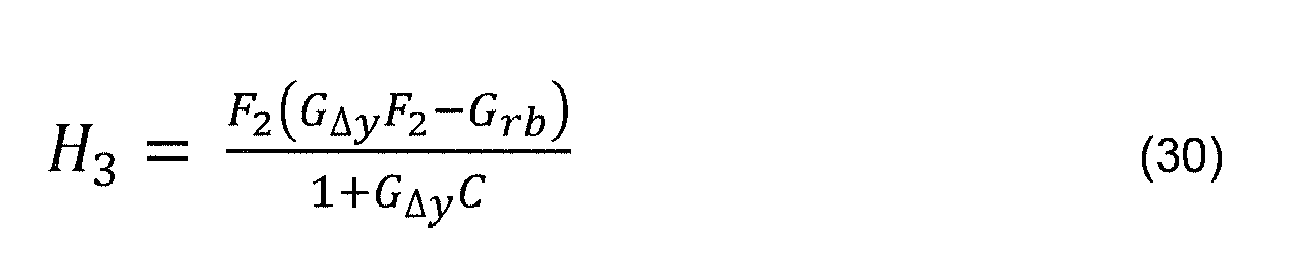
- This L 2-induced gain needs to be less than 1 for each vehicle i, in order to get a string stable system. In effect this can mean that in some cases the string-stability of a platoon of infinite vehicles is lost, however the filters F1, F2, and local controller C can be designed so that the string stability is maintained for a finite number of vehicles even in case of an assumed worst case model uncertainty.
- Below is provided a numerical example for the case of a PD controller as C, and

one gets for a variation of 25% on the vehicle mass and 25% on its cornering stiffnesses, a vehicle platoon which is string stable up to the 8 follower vehicle at a 1 m look-ahead distance (bumper to bumper) at a speed of 40 m/s as shown inFigure 4 . The crossover frequency of the local controller is 0.5 rad/s and the phase margin 45 degrees. - Thus in accordance herewith is proposed an apparatus for lateral control of a host vehicle F during travel in a vehicle platoon. The proposed apparatus comprises: means for acquiring a control signal u and a lateral error ε relative to a target vehicle L of a preceding vehicle T travelling in the vehicle platoon; filter means F1 for filtering the received lateral error ε; filter means F2 for filtering the received control signal u; and controller means C for executing a control algorithm for actuating lateral control of the host vehicle F.
- In embodiments hereof the means for acquiring a control signal u and a lateral error ε relative to a target vehicle L of a preceding vehicle T comprises one or more sensors such as RADAR (RAdio Detection And Ranging) based sensors, vision based sensors, e.g. cameras, or LIDAR (Light Detection And Ranging) based sensors.
- In further embodiments hereof the apparatus further comprises means for relaying information on the host vehicle's F control signal u and the host vehicle's F lateral error ε relative to the target vehicle L to a following vehicle F2 in the vehicle platoon.
- In yet further embodiments hereof the apparatus further comprises means for receiving a control signal u and a lateral error ε relative to the target vehicle L from a preceding vehicle T travelling in the vehicle platoon.
- In still further embodiments hereof the filter means F1 for filtering the received lateral error ε relative to the target vehicle L are arranged to perform filtering such that, given the host vehicles F capabilities G Δy and the host vehicles F controller C, the lateral error ε is prevented from increasing when relayed downwards in the chain of vehicles travelling in the vehicle platoon, and the filter means F2 for filtering the received control signal u are arranged to cancel unwanted effects on the chain of the control signal u of the target vehicle L, and the controller means C are arranged to guarantee local stability of the immediate following of the target vehicle L as described above.
- In accordance with the present application is also envisaged a method for lateral control of a host vehicle during travel in a vehicle platoon. The proposed method comprises the steps of: acquiring a control signal u and a lateral error ε relative to a target vehicle L of a preceding vehicle T travelling in the vehicle platoon; filtering the received lateral error ε; filtering the received control signal u; executing a control algorithm for actuating lateral control of the host vehicle F.
- In accordance with the present application is also envisaged an automotive vehicle comprising an apparatus for lateral control of a host vehicle F during travel in a vehicle platoon as described above.
- The above-described embodiments may be varied within the scope of the following claims.
- Thus, while there have been shown and described and pointed out fundamental novel features of the embodiments herein, it will be understood that various omissions and substitutions and changes in the form and details of the devices illustrated, and in their operation, may be made by those skilled in the art. For example, it is expressly intended that all combinations of those elements and/or method steps which perform substantially the same function in substantially the same way to achieve the same results are equivalent. Moreover, it should be recognized that structures and/or elements and/or method steps shown and/or described in connection with any disclosed form or embodiment herein may be incorporated in any other disclosed or described or suggested form or embodiment as a general matter of design choice.
Claims (7)
- An apparatus for lateral control of a host vehicle (F) during travel in a vehicle platoon, characterized in that it comprises:means for acquiring a control signal u and a lateral error ε relative to a target vehicle (L) of a preceding vehicle (T) travelling in the vehicle platoon;filter means (F1) for filtering the received lateral error ε;filter means (F2) for filtering the received control signal u; andcontroller means (C) for executing a control algorithm for actuating lateral control of the host vehicle (F).
- An apparatus according to claim 1, characterized in that the means for acquiring a control signal u and a lateral error ε relative to a target vehicle (L) of a preceding vehicle (T) comprises one or more sensors such as radar based sensors, vision based sensors or lidar based sensors.
- An apparatus according to claim 1, characterized in that it further comprises means for relaying information on the host vehicle's (F) control signal u and the host vehicle's (F) lateral error ε relative to the target vehicle (L) to a following vehicle (F2) in the vehicle platoon.
- An apparatus according to any one of claims 2 or 3, characterized in that it further comprises means for receiving a control signal u and a lateral error ε relative to the target vehicle (L) from a preceding vehicle (T) travelling in the vehicle platoon.
- An apparatus according to any one of claims 3 or 4, characterized in that the filter means (F1) for filtering the received lateral error ε relative to the target vehicle (L) are arranged to perform filtering such that, given the host vehicles (F) capabilities G Δy and the host vehicles (F) controller C, the lateral error ε is prevented from increasing when relayed downwards in the chain of vehicles travelling in the vehicle platoon, and the filter means (F2) for filtering the received control signal u are arranged to cancel unwanted effects on the chain of the control signal u of the target vehicle (L), and the controller means (C) are arranged to guarantee local stability of the immediate following of the target vehicle (L).
- A method for lateral control of a host vehicle (F) during travel in a vehicle platoon, characterized in that it comprises the steps of:acquiring a control signal u and a lateral error ε relative to a target vehicle (L) of apreceding vehicle (T) travelling in the vehicle platoon;filtering the received lateral error ε;filtering the received control signal u;executing a control algorithm for actuating lateral control of the host vehicle (F).
- An automotive vehicle characterized in that it comprises an apparatus for lateral control of a host vehicle (F) during travel in a vehicle platoon according to any one of claims 1 to 5.
Priority Applications (2)
| Application Number | Priority Date | Filing Date | Title |
|---|---|---|---|
| EP12176186.0A EP2685338B1 (en) | 2012-07-12 | 2012-07-12 | Apparatus and method for lateral control of a host vehicle during travel in a vehicle platoon |
| US13/938,696 US8775060B2 (en) | 2012-07-12 | 2013-07-10 | Apparatus and method for lateral control of a host vehicle during travel in a vehicle platoon |
Applications Claiming Priority (1)
| Application Number | Priority Date | Filing Date | Title |
|---|---|---|---|
| EP12176186.0A EP2685338B1 (en) | 2012-07-12 | 2012-07-12 | Apparatus and method for lateral control of a host vehicle during travel in a vehicle platoon |
Publications (2)
| Publication Number | Publication Date |
|---|---|
| EP2685338A1 true EP2685338A1 (en) | 2014-01-15 |
| EP2685338B1 EP2685338B1 (en) | 2018-04-11 |
Family
ID=46514160
Family Applications (1)
| Application Number | Title | Priority Date | Filing Date |
|---|---|---|---|
| EP12176186.0A Active EP2685338B1 (en) | 2012-07-12 | 2012-07-12 | Apparatus and method for lateral control of a host vehicle during travel in a vehicle platoon |
Country Status (2)
| Country | Link |
|---|---|
| US (1) | US8775060B2 (en) |
| EP (1) | EP2685338B1 (en) |
Cited By (6)
| Publication number | Priority date | Publication date | Assignee | Title |
|---|---|---|---|---|
| EP3210090A4 (en) * | 2014-10-21 | 2018-07-11 | Road Trains LLC | Platooning control via accurate synchronization |
| CN110353577A (en) * | 2019-08-09 | 2019-10-22 | 小狗电器互联网科技(北京)股份有限公司 | A kind of laser radar point cloud data goes the method and Floor-sweeping device of distortion |
| DE102018210371A1 (en) * | 2018-06-26 | 2020-01-02 | Continental Automotive Gmbh | Vehicle network, method for operating the vehicle network, computer program and computer-readable storage medium |
| FR3084506A1 (en) | 2018-07-30 | 2020-01-31 | Renault S.A.S | METHOD FOR ORDERING A MOTOR VEHICLE FOR THE FORMATION OF PLATFORMS |
| CN113147764A (en) * | 2021-06-01 | 2021-07-23 | 吉林大学 | Vehicle control method based on hybrid potential function of cooperative adaptive cruise system |
| US12298774B2 (en) | 2022-05-03 | 2025-05-13 | Smart Information Flow Technologies, LLC | Computer architecture for identification of nonlinear control policies |
Families Citing this family (31)
| Publication number | Priority date | Publication date | Assignee | Title |
|---|---|---|---|---|
| US20170242443A1 (en) | 2015-11-02 | 2017-08-24 | Peloton Technology, Inc. | Gap measurement for vehicle convoying |
| US9582006B2 (en) | 2011-07-06 | 2017-02-28 | Peloton Technology, Inc. | Systems and methods for semi-autonomous convoying of vehicles |
| US10520952B1 (en) | 2011-07-06 | 2019-12-31 | Peloton Technology, Inc. | Devices, systems, and methods for transmitting vehicle data |
| US11334092B2 (en) | 2011-07-06 | 2022-05-17 | Peloton Technology, Inc. | Devices, systems, and methods for transmitting vehicle data |
| US10520581B2 (en) | 2011-07-06 | 2019-12-31 | Peloton Technology, Inc. | Sensor fusion for autonomous or partially autonomous vehicle control |
| US11294396B2 (en) | 2013-03-15 | 2022-04-05 | Peloton Technology, Inc. | System and method for implementing pre-cognition braking and/or avoiding or mitigation risks among platooning vehicles |
| US20180210463A1 (en) | 2013-03-15 | 2018-07-26 | Peloton Technology, Inc. | System and method for implementing pre-cognition braking and/or avoiding or mitigation risks among platooning vehicles |
| JP5737316B2 (en) * | 2013-04-17 | 2015-06-17 | 株式会社デンソー | Convoy travel system |
| KR20150084112A (en) * | 2014-01-13 | 2015-07-22 | 한국전자통신연구원 | System and method for controlling vihicle at intersection |
| US9892296B2 (en) | 2014-11-12 | 2018-02-13 | Joseph E. Kovarik | Method and system for autonomous vehicles |
| DE102015016758A1 (en) * | 2015-12-23 | 2017-06-29 | Daimler Ag | Method for moving, in particular for controlling or regulating, a vehicle convoy |
| US10204519B2 (en) | 2015-12-25 | 2019-02-12 | Ozyegin Universitesi | Communication between vehicles of a platoon |
| US9632507B1 (en) | 2016-01-29 | 2017-04-25 | Meritor Wabco Vehicle Control Systems | System and method for adjusting vehicle platoon distances based on predicted external perturbations |
| JP6243942B2 (en) * | 2016-03-17 | 2017-12-06 | 株式会社Subaru | Vehicle travel control device |
| WO2017210200A1 (en) | 2016-05-31 | 2017-12-07 | Peloton Technology, Inc. | Platoon controller state machine |
| US10068485B2 (en) * | 2016-08-15 | 2018-09-04 | Ford Global Technologies, Llc | Platooning autonomous vehicle navigation sensory exchange |
| US10369998B2 (en) | 2016-08-22 | 2019-08-06 | Peloton Technology, Inc. | Dynamic gap control for automated driving |
| JP6690056B2 (en) | 2016-08-22 | 2020-04-28 | ぺロトン テクノロジー インコーポレイテッド | Control system architecture for motor vehicle |
| SE541346C2 (en) * | 2016-08-31 | 2019-07-23 | Scania Cv Ab | Method and control unit for maintaining a formation of vehicles co-ordinated to perform a common task |
| JP6822480B2 (en) * | 2016-09-26 | 2021-01-27 | 日産自動車株式会社 | Track setting method and track setting device |
| US10683002B2 (en) | 2017-06-27 | 2020-06-16 | Toyota Motor Engineering & Manufacturing North America, Inc. | Efficient acceleration from surrounding vehicles |
| KR102288799B1 (en) | 2017-09-27 | 2021-08-11 | 현대모비스 주식회사 | Apparatus for controlling group driving and method thereof |
| JP6795792B2 (en) * | 2017-09-28 | 2020-12-02 | トヨタ自動車株式会社 | Driving support device |
| JP6822386B2 (en) * | 2017-11-30 | 2021-01-27 | トヨタ自動車株式会社 | Formation running system |
| KR20190075221A (en) * | 2017-12-21 | 2019-07-01 | 현대자동차주식회사 | Vehicle, and control method for the same |
| DE112018007425T5 (en) * | 2018-04-02 | 2021-03-11 | Mitsubishi Electric Corporation | Client device, data transmission method and data acquisition system |
| US10899323B2 (en) | 2018-07-08 | 2021-01-26 | Peloton Technology, Inc. | Devices, systems, and methods for vehicle braking |
| US10762791B2 (en) | 2018-10-29 | 2020-09-01 | Peloton Technology, Inc. | Systems and methods for managing communications between vehicles |
| US11427196B2 (en) | 2019-04-15 | 2022-08-30 | Peloton Technology, Inc. | Systems and methods for managing tractor-trailers |
| CN113771880B (en) * | 2021-10-13 | 2023-01-06 | 厦门理工学院 | Vehicle following automatic driving method and system suitable for vehicle formation |
| US12260760B2 (en) | 2022-11-11 | 2025-03-25 | Ford Global Technologies, Llc | Remote sensor access |
Citations (2)
| Publication number | Priority date | Publication date | Assignee | Title |
|---|---|---|---|---|
| US5781119A (en) | 1995-03-14 | 1998-07-14 | Toyota Jidosha Kabushiki Kaisha | Vehicle guiding system |
| US20110196514A1 (en) * | 2010-02-10 | 2011-08-11 | Chengyu Cao | Adaptive control for uncertain nonlinear multi-input multi-output systems |
Family Cites Families (2)
| Publication number | Priority date | Publication date | Assignee | Title |
|---|---|---|---|---|
| US8352112B2 (en) * | 2009-04-06 | 2013-01-08 | GM Global Technology Operations LLC | Autonomous vehicle management |
| US8620517B2 (en) * | 2012-02-21 | 2013-12-31 | Toyota Mototr Engineering & Manufacturing North America, Inc. | Vehicular platooning using distributed receding horizon control |
-
2012
- 2012-07-12 EP EP12176186.0A patent/EP2685338B1/en active Active
-
2013
- 2013-07-10 US US13/938,696 patent/US8775060B2/en active Active
Patent Citations (2)
| Publication number | Priority date | Publication date | Assignee | Title |
|---|---|---|---|---|
| US5781119A (en) | 1995-03-14 | 1998-07-14 | Toyota Jidosha Kabushiki Kaisha | Vehicle guiding system |
| US20110196514A1 (en) * | 2010-02-10 | 2011-08-11 | Chengyu Cao | Adaptive control for uncertain nonlinear multi-input multi-output systems |
Non-Patent Citations (3)
| Title |
|---|
| ARASH IDELCHI ET AL: "Lateral Control of Vehicle Platoons", GÖTEBORG, SWEDEN, 2011, 1 January 2011 (2011-01-01), Göteborg, Sweden, 2011, XP055044353, Retrieved from the Internet <URL:http://publications.lib.chalmers.se/records/fulltext/153348.pdf> [retrieved on 20121115] * |
| LEE G D ET AL: "Longitudinal and lateral control system development for a platoon of vehicles", INTELLIGENT TRANSPORTATION SYSTEMS, 1999. PROCEEDINGS. 1999 IEEE/IEEJ/ JSAI INTERNATIONAL CONFERENCE ON TOKYO, JAPAN 5-8 OCT. 1999, PISCATAWAY, NJ, USA,IEEE, US, 5 October 1999 (1999-10-05), pages 605 - 610, XP010369958, ISBN: 978-0-7803-4975-9, DOI: 10.1109/ITSC.1999.821130 * |
| RICHARD H MIDDLETON ET AL: "String Instability in Classes of Linear Time Invariant Formation Control With Limited Communication Range", IEEE TRANSACTIONS ON AUTOMATIC CONTROL, IEEE SERVICE CENTER, LOS ALAMITOS, CA, US, vol. 55, no. 7, 1 July 2010 (2010-07-01), pages 1519 - 1530, XP011301409, ISSN: 0018-9286 * |
Cited By (9)
| Publication number | Priority date | Publication date | Assignee | Title |
|---|---|---|---|---|
| EP3210090A4 (en) * | 2014-10-21 | 2018-07-11 | Road Trains LLC | Platooning control via accurate synchronization |
| US10488869B2 (en) | 2014-10-21 | 2019-11-26 | Road Trains Llc | Platooning control via accurate synchronization |
| DE102018210371A1 (en) * | 2018-06-26 | 2020-01-02 | Continental Automotive Gmbh | Vehicle network, method for operating the vehicle network, computer program and computer-readable storage medium |
| DE102018210371B4 (en) | 2018-06-26 | 2020-07-09 | Continental Automotive Gmbh | Vehicle network, method for operating the vehicle network, computer program and computer-readable storage medium |
| FR3084506A1 (en) | 2018-07-30 | 2020-01-31 | Renault S.A.S | METHOD FOR ORDERING A MOTOR VEHICLE FOR THE FORMATION OF PLATFORMS |
| CN110353577A (en) * | 2019-08-09 | 2019-10-22 | 小狗电器互联网科技(北京)股份有限公司 | A kind of laser radar point cloud data goes the method and Floor-sweeping device of distortion |
| CN110353577B (en) * | 2019-08-09 | 2020-12-08 | 小狗电器互联网科技(北京)股份有限公司 | Laser radar point cloud data distortion removal method and sweeping device |
| CN113147764A (en) * | 2021-06-01 | 2021-07-23 | 吉林大学 | Vehicle control method based on hybrid potential function of cooperative adaptive cruise system |
| US12298774B2 (en) | 2022-05-03 | 2025-05-13 | Smart Information Flow Technologies, LLC | Computer architecture for identification of nonlinear control policies |
Also Published As
| Publication number | Publication date |
|---|---|
| US20140019031A1 (en) | 2014-01-16 |
| EP2685338B1 (en) | 2018-04-11 |
| US8775060B2 (en) | 2014-07-08 |
Similar Documents
| Publication | Publication Date | Title |
|---|---|---|
| EP2685338B1 (en) | Apparatus and method for lateral control of a host vehicle during travel in a vehicle platoon | |
| CN110244713B (en) | Intelligent vehicle lane change track planning system and method based on artificial potential field method | |
| CN106926844B (en) | A kind of dynamic auto driving lane-change method for planning track based on real time environment information | |
| CN111681452B (en) | Unmanned vehicle dynamic lane change track planning method based on Frenet coordinate system | |
| Li et al. | Advanced motion control and sensing for intelligent vehicles | |
| US20210146919A1 (en) | Vehicle path planning | |
| CN102076542B (en) | follow-through control | |
| CN110877611B (en) | Obstacle avoidance device and obstacle avoidance path generation device | |
| CN110286681A (en) | A lane-changing trajectory planning method for dynamic automatic driving on curves with variable curvature | |
| GB2570887A (en) | A system for a vehicle | |
| JP7667800B2 (en) | Routing control module, related routing control device and related method - Patents.com | |
| Farag et al. | Dynamics platooning model and protocols for self-driving vehicles | |
| US20230322228A1 (en) | Vehicle control apparatus | |
| Pauca et al. | Control architecture for cooperative autonomous vehicles driving in platoons at highway speeds | |
| KR20180025611A (en) | Autonomous driving system and autonomous driving method thereof | |
| Khalifa et al. | Vehicles platooning in urban environment: Consensus-based longitudinal control with limited communications capabilities | |
| US20230174059A1 (en) | Lane-based vehicle operations | |
| CN117325858A (en) | Queue predictive cruising and lane changing control system and method based on cloud control platform | |
| Bienemann et al. | Model predictive control for autonomous vehicle following | |
| Yue et al. | Automated hazard escaping trajectory planning/tracking control framework for vehicles subject to tire blowout on expressway | |
| JP2024535025A (en) | Method for planning a driving maneuver trajectory of a powered vehicle, computer program product, computer readable storage medium, and vehicle - Patents.com | |
| Jia et al. | A dynamic lane-changing trajectory planning scheme for autonomous vehicles on structured road | |
| CN107992039A (en) | A kind of method for planning track based on flow field under dynamic environment | |
| Shin et al. | Effects of wireless communication on integrated risk management based automated vehicle | |
| Nordell | Trajectory planning for autonomous vehicles and cooperative driving |
Legal Events
| Date | Code | Title | Description |
|---|---|---|---|
| PUAI | Public reference made under article 153(3) epc to a published international application that has entered the european phase |
Free format text: ORIGINAL CODE: 0009012 |
|
| AK | Designated contracting states |
Kind code of ref document: A1 Designated state(s): AL AT BE BG CH CY CZ DE DK EE ES FI FR GB GR HR HU IE IS IT LI LT LU LV MC MK MT NL NO PL PT RO RS SE SI SK SM TR |
|
| AX | Request for extension of the european patent |
Extension state: BA ME |
|
| 17P | Request for examination filed |
Effective date: 20140715 |
|
| RBV | Designated contracting states (corrected) |
Designated state(s): AL AT BE BG CH CY CZ DE DK EE ES FI FR GB GR HR HU IE IS IT LI LT LU LV MC MK MT NL NO PL PT RO RS SE SI SK SM TR |
|
| 17Q | First examination report despatched |
Effective date: 20160310 |
|
| REG | Reference to a national code |
Ref country code: DE Ref legal event code: R079 Ref document number: 602012044976 Country of ref document: DE Free format text: PREVIOUS MAIN CLASS: G05D0001020000 Ipc: G08G0001000000 |
|
| GRAP | Despatch of communication of intention to grant a patent |
Free format text: ORIGINAL CODE: EPIDOSNIGR1 |
|
| RIC1 | Information provided on ipc code assigned before grant |
Ipc: G08G 1/00 20060101AFI20171123BHEP Ipc: B60T 8/1755 20060101ALI20171123BHEP Ipc: G05D 1/02 20060101ALI20171123BHEP Ipc: B60W 30/12 20060101ALI20171123BHEP |
|
| INTG | Intention to grant announced |
Effective date: 20171220 |
|
| GRAS | Grant fee paid |
Free format text: ORIGINAL CODE: EPIDOSNIGR3 |
|
| GRAA | (expected) grant |
Free format text: ORIGINAL CODE: 0009210 |
|
| AK | Designated contracting states |
Kind code of ref document: B1 Designated state(s): AL AT BE BG CH CY CZ DE DK EE ES FI FR GB GR HR HU IE IS IT LI LT LU LV MC MK MT NL NO PL PT RO RS SE SI SK SM TR |
|
| REG | Reference to a national code |
Ref country code: GB Ref legal event code: FG4D |
|
| REG | Reference to a national code |
Ref country code: CH Ref legal event code: EP |
|
| REG | Reference to a national code |
Ref country code: AT Ref legal event code: REF Ref document number: 988808 Country of ref document: AT Kind code of ref document: T Effective date: 20180415 |
|
| REG | Reference to a national code |
Ref country code: IE Ref legal event code: FG4D |
|
| REG | Reference to a national code |
Ref country code: DE Ref legal event code: R096 Ref document number: 602012044976 Country of ref document: DE |
|
| REG | Reference to a national code |
Ref country code: SE Ref legal event code: TRGR |
|
| REG | Reference to a national code |
Ref country code: NL Ref legal event code: MP Effective date: 20180411 |
|
| REG | Reference to a national code |
Ref country code: LT Ref legal event code: MG4D |
|
| PG25 | Lapsed in a contracting state [announced via postgrant information from national office to epo] |
Ref country code: NL Free format text: LAPSE BECAUSE OF FAILURE TO SUBMIT A TRANSLATION OF THE DESCRIPTION OR TO PAY THE FEE WITHIN THE PRESCRIBED TIME-LIMIT Effective date: 20180411 |
|
| PG25 | Lapsed in a contracting state [announced via postgrant information from national office to epo] |
Ref country code: FI Free format text: LAPSE BECAUSE OF FAILURE TO SUBMIT A TRANSLATION OF THE DESCRIPTION OR TO PAY THE FEE WITHIN THE PRESCRIBED TIME-LIMIT Effective date: 20180411 Ref country code: NO Free format text: LAPSE BECAUSE OF FAILURE TO SUBMIT A TRANSLATION OF THE DESCRIPTION OR TO PAY THE FEE WITHIN THE PRESCRIBED TIME-LIMIT Effective date: 20180711 Ref country code: BG Free format text: LAPSE BECAUSE OF FAILURE TO SUBMIT A TRANSLATION OF THE DESCRIPTION OR TO PAY THE FEE WITHIN THE PRESCRIBED TIME-LIMIT Effective date: 20180711 Ref country code: AL Free format text: LAPSE BECAUSE OF FAILURE TO SUBMIT A TRANSLATION OF THE DESCRIPTION OR TO PAY THE FEE WITHIN THE PRESCRIBED TIME-LIMIT Effective date: 20180411 Ref country code: PL Free format text: LAPSE BECAUSE OF FAILURE TO SUBMIT A TRANSLATION OF THE DESCRIPTION OR TO PAY THE FEE WITHIN THE PRESCRIBED TIME-LIMIT Effective date: 20180411 Ref country code: LT Free format text: LAPSE BECAUSE OF FAILURE TO SUBMIT A TRANSLATION OF THE DESCRIPTION OR TO PAY THE FEE WITHIN THE PRESCRIBED TIME-LIMIT Effective date: 20180411 Ref country code: ES Free format text: LAPSE BECAUSE OF FAILURE TO SUBMIT A TRANSLATION OF THE DESCRIPTION OR TO PAY THE FEE WITHIN THE PRESCRIBED TIME-LIMIT Effective date: 20180411 |
|
| PG25 | Lapsed in a contracting state [announced via postgrant information from national office to epo] |
Ref country code: LV Free format text: LAPSE BECAUSE OF FAILURE TO SUBMIT A TRANSLATION OF THE DESCRIPTION OR TO PAY THE FEE WITHIN THE PRESCRIBED TIME-LIMIT Effective date: 20180411 Ref country code: GR Free format text: LAPSE BECAUSE OF FAILURE TO SUBMIT A TRANSLATION OF THE DESCRIPTION OR TO PAY THE FEE WITHIN THE PRESCRIBED TIME-LIMIT Effective date: 20180712 Ref country code: HR Free format text: LAPSE BECAUSE OF FAILURE TO SUBMIT A TRANSLATION OF THE DESCRIPTION OR TO PAY THE FEE WITHIN THE PRESCRIBED TIME-LIMIT Effective date: 20180411 Ref country code: RS Free format text: LAPSE BECAUSE OF FAILURE TO SUBMIT A TRANSLATION OF THE DESCRIPTION OR TO PAY THE FEE WITHIN THE PRESCRIBED TIME-LIMIT Effective date: 20180411 |
|
| REG | Reference to a national code |
Ref country code: AT Ref legal event code: MK05 Ref document number: 988808 Country of ref document: AT Kind code of ref document: T Effective date: 20180411 |
|
| PG25 | Lapsed in a contracting state [announced via postgrant information from national office to epo] |
Ref country code: PT Free format text: LAPSE BECAUSE OF FAILURE TO SUBMIT A TRANSLATION OF THE DESCRIPTION OR TO PAY THE FEE WITHIN THE PRESCRIBED TIME-LIMIT Effective date: 20180813 |
|
| REG | Reference to a national code |
Ref country code: DE Ref legal event code: R097 Ref document number: 602012044976 Country of ref document: DE |
|
| PG25 | Lapsed in a contracting state [announced via postgrant information from national office to epo] |
Ref country code: EE Free format text: LAPSE BECAUSE OF FAILURE TO SUBMIT A TRANSLATION OF THE DESCRIPTION OR TO PAY THE FEE WITHIN THE PRESCRIBED TIME-LIMIT Effective date: 20180411 Ref country code: DK Free format text: LAPSE BECAUSE OF FAILURE TO SUBMIT A TRANSLATION OF THE DESCRIPTION OR TO PAY THE FEE WITHIN THE PRESCRIBED TIME-LIMIT Effective date: 20180411 Ref country code: AT Free format text: LAPSE BECAUSE OF FAILURE TO SUBMIT A TRANSLATION OF THE DESCRIPTION OR TO PAY THE FEE WITHIN THE PRESCRIBED TIME-LIMIT Effective date: 20180411 Ref country code: CZ Free format text: LAPSE BECAUSE OF FAILURE TO SUBMIT A TRANSLATION OF THE DESCRIPTION OR TO PAY THE FEE WITHIN THE PRESCRIBED TIME-LIMIT Effective date: 20180411 Ref country code: RO Free format text: LAPSE BECAUSE OF FAILURE TO SUBMIT A TRANSLATION OF THE DESCRIPTION OR TO PAY THE FEE WITHIN THE PRESCRIBED TIME-LIMIT Effective date: 20180411 Ref country code: SK Free format text: LAPSE BECAUSE OF FAILURE TO SUBMIT A TRANSLATION OF THE DESCRIPTION OR TO PAY THE FEE WITHIN THE PRESCRIBED TIME-LIMIT Effective date: 20180411 |
|
| PLBE | No opposition filed within time limit |
Free format text: ORIGINAL CODE: 0009261 |
|
| STAA | Information on the status of an ep patent application or granted ep patent |
Free format text: STATUS: NO OPPOSITION FILED WITHIN TIME LIMIT |
|
| PG25 | Lapsed in a contracting state [announced via postgrant information from national office to epo] |
Ref country code: IT Free format text: LAPSE BECAUSE OF FAILURE TO SUBMIT A TRANSLATION OF THE DESCRIPTION OR TO PAY THE FEE WITHIN THE PRESCRIBED TIME-LIMIT Effective date: 20180411 Ref country code: SM Free format text: LAPSE BECAUSE OF FAILURE TO SUBMIT A TRANSLATION OF THE DESCRIPTION OR TO PAY THE FEE WITHIN THE PRESCRIBED TIME-LIMIT Effective date: 20180411 |
|
| REG | Reference to a national code |
Ref country code: CH Ref legal event code: PL |
|
| 26N | No opposition filed |
Effective date: 20190114 |
|
| PG25 | Lapsed in a contracting state [announced via postgrant information from national office to epo] |
Ref country code: MC Free format text: LAPSE BECAUSE OF FAILURE TO SUBMIT A TRANSLATION OF THE DESCRIPTION OR TO PAY THE FEE WITHIN THE PRESCRIBED TIME-LIMIT Effective date: 20180411 Ref country code: LU Free format text: LAPSE BECAUSE OF NON-PAYMENT OF DUE FEES Effective date: 20180712 |
|
| REG | Reference to a national code |
Ref country code: BE Ref legal event code: MM Effective date: 20180731 |
|
| REG | Reference to a national code |
Ref country code: IE Ref legal event code: MM4A |
|
| PG25 | Lapsed in a contracting state [announced via postgrant information from national office to epo] |
Ref country code: LI Free format text: LAPSE BECAUSE OF NON-PAYMENT OF DUE FEES Effective date: 20180731 Ref country code: FR Free format text: LAPSE BECAUSE OF NON-PAYMENT OF DUE FEES Effective date: 20180731 Ref country code: IE Free format text: LAPSE BECAUSE OF NON-PAYMENT OF DUE FEES Effective date: 20180712 Ref country code: CH Free format text: LAPSE BECAUSE OF NON-PAYMENT OF DUE FEES Effective date: 20180731 |
|
| PG25 | Lapsed in a contracting state [announced via postgrant information from national office to epo] |
Ref country code: SI Free format text: LAPSE BECAUSE OF FAILURE TO SUBMIT A TRANSLATION OF THE DESCRIPTION OR TO PAY THE FEE WITHIN THE PRESCRIBED TIME-LIMIT Effective date: 20180411 Ref country code: BE Free format text: LAPSE BECAUSE OF NON-PAYMENT OF DUE FEES Effective date: 20180731 |
|
| PGFP | Annual fee paid to national office [announced via postgrant information from national office to epo] |
Ref country code: SE Payment date: 20190718 Year of fee payment: 8 |
|
| PGFP | Annual fee paid to national office [announced via postgrant information from national office to epo] |
Ref country code: GB Payment date: 20190710 Year of fee payment: 8 |
|
| PG25 | Lapsed in a contracting state [announced via postgrant information from national office to epo] |
Ref country code: MT Free format text: LAPSE BECAUSE OF NON-PAYMENT OF DUE FEES Effective date: 20180712 |
|
| PG25 | Lapsed in a contracting state [announced via postgrant information from national office to epo] |
Ref country code: TR Free format text: LAPSE BECAUSE OF FAILURE TO SUBMIT A TRANSLATION OF THE DESCRIPTION OR TO PAY THE FEE WITHIN THE PRESCRIBED TIME-LIMIT Effective date: 20180411 |
|
| PG25 | Lapsed in a contracting state [announced via postgrant information from national office to epo] |
Ref country code: HU Free format text: LAPSE BECAUSE OF FAILURE TO SUBMIT A TRANSLATION OF THE DESCRIPTION OR TO PAY THE FEE WITHIN THE PRESCRIBED TIME-LIMIT; INVALID AB INITIO Effective date: 20120712 |
|
| PG25 | Lapsed in a contracting state [announced via postgrant information from national office to epo] |
Ref country code: MK Free format text: LAPSE BECAUSE OF NON-PAYMENT OF DUE FEES Effective date: 20180411 Ref country code: CY Free format text: LAPSE BECAUSE OF FAILURE TO SUBMIT A TRANSLATION OF THE DESCRIPTION OR TO PAY THE FEE WITHIN THE PRESCRIBED TIME-LIMIT Effective date: 20180411 |
|
| PG25 | Lapsed in a contracting state [announced via postgrant information from national office to epo] |
Ref country code: IS Free format text: LAPSE BECAUSE OF FAILURE TO SUBMIT A TRANSLATION OF THE DESCRIPTION OR TO PAY THE FEE WITHIN THE PRESCRIBED TIME-LIMIT Effective date: 20180811 |
|
| REG | Reference to a national code |
Ref country code: SE Ref legal event code: EUG |
|
| GBPC | Gb: european patent ceased through non-payment of renewal fee |
Effective date: 20200712 |
|
| PG25 | Lapsed in a contracting state [announced via postgrant information from national office to epo] |
Ref country code: GB Free format text: LAPSE BECAUSE OF NON-PAYMENT OF DUE FEES Effective date: 20200712 |
|
| PG25 | Lapsed in a contracting state [announced via postgrant information from national office to epo] |
Ref country code: SE Free format text: LAPSE BECAUSE OF NON-PAYMENT OF DUE FEES Effective date: 20200713 |
|
| P01 | Opt-out of the competence of the unified patent court (upc) registered |
Effective date: 20231212 |
|
| PGFP | Annual fee paid to national office [announced via postgrant information from national office to epo] |
Ref country code: DE Payment date: 20250620 Year of fee payment: 14 |