EP2685252B1 - Conduit sensor device and process for modifying a magnetic field of a conduit sensor device - Google Patents
Conduit sensor device and process for modifying a magnetic field of a conduit sensor device Download PDFInfo
- Publication number
- EP2685252B1 EP2685252B1 EP13156720.8A EP13156720A EP2685252B1 EP 2685252 B1 EP2685252 B1 EP 2685252B1 EP 13156720 A EP13156720 A EP 13156720A EP 2685252 B1 EP2685252 B1 EP 2685252B1
- Authority
- EP
- European Patent Office
- Prior art keywords
- magnet rotor
- rotor assembly
- magnets
- magnet
- worm
- Prior art date
- Legal status (The legal status is an assumption and is not a legal conclusion. Google has not performed a legal analysis and makes no representation as to the accuracy of the status listed.)
- Active
Links
Images
















Classifications
-
- G—PHYSICS
- G01—MEASURING; TESTING
- G01N—INVESTIGATING OR ANALYSING MATERIALS BY DETERMINING THEIR CHEMICAL OR PHYSICAL PROPERTIES
- G01N27/00—Investigating or analysing materials by the use of electric, electrochemical, or magnetic means
- G01N27/72—Investigating or analysing materials by the use of electric, electrochemical, or magnetic means by investigating magnetic variables
- G01N27/82—Investigating or analysing materials by the use of electric, electrochemical, or magnetic means by investigating magnetic variables for investigating the presence of flaws
-
- F—MECHANICAL ENGINEERING; LIGHTING; HEATING; WEAPONS; BLASTING
- F16—ENGINEERING ELEMENTS AND UNITS; GENERAL MEASURES FOR PRODUCING AND MAINTAINING EFFECTIVE FUNCTIONING OF MACHINES OR INSTALLATIONS; THERMAL INSULATION IN GENERAL
- F16H—GEARING
- F16H1/00—Toothed gearings for conveying rotary motion
- F16H1/02—Toothed gearings for conveying rotary motion without gears having orbital motion
- F16H1/20—Toothed gearings for conveying rotary motion without gears having orbital motion involving more than two intermeshing members
- F16H1/22—Toothed gearings for conveying rotary motion without gears having orbital motion involving more than two intermeshing members with a plurality of driving or driven shafts; with arrangements for dividing torque between two or more intermediate shafts
- F16H1/222—Toothed gearings for conveying rotary motion without gears having orbital motion involving more than two intermeshing members with a plurality of driving or driven shafts; with arrangements for dividing torque between two or more intermediate shafts with non-parallel axes
- F16H1/225—Toothed gearings for conveying rotary motion without gears having orbital motion involving more than two intermeshing members with a plurality of driving or driven shafts; with arrangements for dividing torque between two or more intermediate shafts with non-parallel axes with two or more worm and worm-wheel gearings
-
- G—PHYSICS
- G01—MEASURING; TESTING
- G01N—INVESTIGATING OR ANALYSING MATERIALS BY DETERMINING THEIR CHEMICAL OR PHYSICAL PROPERTIES
- G01N2291/00—Indexing codes associated with group G01N29/00
- G01N2291/26—Scanned objects
- G01N2291/263—Surfaces
- G01N2291/2636—Surfaces cylindrical from inside
Definitions
- the invention is in the field of pipeline inspection devices/sensors, especially conduit sensor device and a process for modifying a magnetic field of a conduit sensor device
- US- 6,762,602 proposed a "device, e.g. an inspection pig, for inspecting conduits made from ferromagnetic materials, such as pipelines, for faults, cracks, corrosion or the like, comprising at least one pulling element, a supporting structure of variable circumference, disposed on the pulling element and comprising substantially radially disposed supporting arms each of which is pivotable about axes disposed perpendicular to the longitudinal central axis of the pulling element, and several permanent magnets disposed at the circumference of the supporting structure for generating a magnetic filed, and with sensors.” Further, US- 6,762,602 states, pertinent part: "[f]or strengthening or weakening the magnetic field generated by the permanent magnet in dependence on the circumference of the supporting structure or in dependence on the lateral separation between the permanent magnets.
- the permanent magnets are associated with further magnets having a magnetic field which can be varied in direction or strength.
- the further magnets associated with the permanent magnets are permanent magnets, wherein the direction of their magnetic field can be changed by turning using an electric or mechanical actuator.
- coils are used as magnets, which can be supplied with a variable current.” See, the Abstract of US- 6,762,6021 .
- the diametrical size of the conduit, the thickness of the conduit, and the lateral separation of the poles of the magnet are factors in the performance of the sensor.
- Sensors such as piezo-electric, electro-acoustic, and electromagnetic sensors such as Hall, stray field and eddy current sensors may be used.
- US- 6,762,602 does not effectively shunt the magnetic field produced by the poles through use of respective rotatable magnets. Additionally, the drive system of the rotatable magnets disclosed in US-6,762,602 involves a mechanical system using springs and a toothed wheel with a selected diameter and selected number of teeth. The diameter and the number of teeth may be changed to control the rotatable magnet. Further, a spring is necessary for each of the rotatable magnets and adjustment of those magnets in a coordinated manner is difficult, and, therefore, control of the magnetic field is difficult.
- One of the poles in the US- 6,762,602 may be adjusted differently than the other pole because the springs and toothed gears cannot be matched or properly controlled. Spring constants and biasing of the rotatable magnets in US- 6,762,602 may not be equal and, hence, contribution of each of the poles to the magnetic field may be different.
- US- 6,762,602 further discloses an electrically driven toothed wheel which is controlled by appropriate electric, electronic or mechanical sensor element for determining the lateral separation between the parallelogram supports.
- an electrically driven toothed wheel which is controlled by appropriate electric, electronic or mechanical sensor element for determining the lateral separation between the parallelogram supports.
- a more effective magnetic shunt which substantially completely reduces the magnetic field associated with a plurality of inner peripheral sensors is needed for unpiggable pipe lines.
- So-called unpiggable pipe lines require substantial cancellation of the magnetic field caused by permanent magnets used in conduit sensors placed in proximity to the conduit/pipe line. When the field created by the permanent magnets is substantially cancelled, the sensor may be drawn more easily through the pipeline as the sensor and its supporting structure are no longer magnetically attracted to the walls of the conduit/pipeline.
- EP 2 407 778 discloses a conduit sensor device including first and second pairs of permanent magnets.
- First and second rotor shunts include first and second rotatable magnets and interposed between the first and second pairs of permanent magnets, respectively.
- a shunt shaft includes a first helical worm gear and a second helical worm gear mounted thereon.
- the first rotor shunt includes a first rotatable magnet and a first rotor gear locked together.
- the first helical worm gear meshing with the first rotor gear driving the first rotor gear and the first rotatable magnet.
- the second rotor shunt includes a second rotatable magnet and a second rotor gear locked together.
- the second helical worm gear meshes with the second rotor gear driving the second rotor gear and the second rotatable magnet.;
- the surface areas of the first and second pairs of permanent magnets equals the surface area of the first and second rotatable magnets.
- conduit sensor device Use of a conduit sensor device requires application of north and south poles in proximity to the conduit/pipe line wall which creates a magnetic field extending into the wall of the conduit/pipe line. Control of the magnetic field which enters the conduit/pipe line is necessary for the correct interpretation of data obtained from the sensors. Sensors, such as a Hall effect sensors, measure anomalies such as cracks and deterioration of the structure of the conduit/pipeline when a magnetic field is imparted in the conduit/pipeline. Control of the magnetic field imparted in the conduit/pipeline is important as it allows correct interpretation of the data generated from the sensors. As such, a conduit sensor device which accurately controls the magnetic field in the conduit/pipeline wall is needed.
- conduit sensor device of the invention comprises the features of claims 1 and the Method of the invention comprises the features of claim 12.
- Preferred embodiments of the invention are characterized in the dependent claims.
- the conduit sensor disclosed herein controls the magnetic field as required to obtain accurate data and to allow movement through a pipeline or conduit. Additionally, the conduit sensor disclosed herein is self-propelled in two directions, forwardly and rearwardly.
- Each conduit sensor device includes several sensors associated therewith and each device covers a sector of the pipeline/conduit. Any number of conduit sensors may be used to form an inspection pig.
- Each conduit sensor device includes a magnetic shunt device.
- the magnetic shunt device is used to effectively turn off the magnetic field.
- the inspection pig is propelled through the pipeline/conduit by drive means which are disclosed herein.
- Each of the conduit sensor devices propels the conduit sensor device through the pipeline to be inspected.
- the magnetic shunt device enables the curtailment of the magnetic field in the pipeline/conduit making movement of the inspection pig within the interior of the pipeline/conduit and through valves and other obstructions inside the pipeline easier.
- the magnetic shunt device imparts an appropriately adjustable magnetic field into the pipeline/conduit as dictated by the operation of the inspection pig and/or as required for other reasons such as comparison of the data presently being taken against previously taken data for a given conduit/pipeline.
- a conduit sensor device comprising a first end portion and a second end portion.
- a first magnet rotor assembly resides proximate the first end portion of the device and is rotatable between first and second positions.
- a second magnet rotor assembly resides proximate the second end portion of the device and is rotatable between first and second positions.
- the first position of the first magnet rotor assembly in combination with the first position of the second magnet rotor assembly creates the maximum strength magnetic field.
- the second position of the second magnet rotor assembly in combination with the second position of the second magnet rotor assembly effectively completely shunts the magnetic field rendering no magnetic field.
- the first magnetic rotor assembly and the second magnetic rotor assembly move in unison under the control of a shunt motor. In other words if the orientation of the first magnet rotor assembly is rotated 45° then the orientation of the second magnet rotor assembly is rotated 45° in the same direction when viewed from the first end of the device.
- a first and third rotor assembly reside proximate the first end of the conduit sensor device and a second and fourth rotor assembly reside proximate the second end of the conduit sensor device.
- the first and third rotor assemblies proximate the first end are rotated 90° such that the top portions thereof face each other at the conclusion of the 90° rotation canceling the magnetic field when the shunt shaft is rotated counter clockwise with respect to the first end.
- the second and fourth rotor assemblies proximate the second end are rotated 90° such that the top portions thereof face away from each other at the conclusion of the 90° rotation canceling the magnetic field when the shunt shaft is rotated counter clockwise with respect to the first end.
- the first magnet rotor assembly includes a first plurality of magnets axially arranged about a first axis, the first magnet rotor assembly includes a first top portion and a first bottom portion, and, the first top and bottom portions secure the first plurality of magnets within the first magnet rotor assembly.
- the second magnet rotor assembly includes a second plurality of magnets axially arranged about a second axis, the second magnet rotor assembly includes a second top portion and a second bottom portion, and, the second top and bottom portions secure the second plurality of magnets within the second magnet rotor assembly.
- the first position of the first magnet rotor assembly orients the north pole of each of the first plurality of magnets radially outwardly.
- the first position of the second magnet rotor assembly orients the south pole of each of the second plurality of magnets radially outwardly.
- the second position of the first magnet rotor assembly orients the north pole of each of the first plurality of magnets at an angle of 90° with respect to the first position; and, the second position of the second magnet rotor assembly orients the north pole of each of the second plurality of magnets at an angle of 90° with respect to said first position.
- the direction of rotation depends on the direction of rotation of the shunt shaft with respect to the first end.
- a worm drive is a gear arrangement in which a worm meshes with a worm wheel sometimes referred to as a worm gear.
- the terms "worm wheel” and “worm gear” are synonymous.
- the worm drives the worm wheel.
- the worm wheel is similar in appearance to a spur gear.
- a worm is essentially a gear in the form of a screw.
- the conduit sensor device includes a first drive mechanism for rotating the first magnet rotor assembly from the first position to the second position and a second drive mechanism for rotating the second magnet rotor assembly from the first position to the second position.
- the first drive mechanism includes a first vertical shunt worm for rotating the first magnet rotor assembly.
- the second drive mechanism includes a second vertical shunt worm for rotating the second magnet rotor assembly.
- a shunt shaft extends between the first end portion of the device to the second end portion of the device.
- a first shunt shaft worm and a second shunt shaft worm are affixed to the shunt shaft.
- a first shunt worm wheel engages the first shunt shaft worm and a second shunt worm wheel engages the second shunt shaft worm.
- the first shunt worm wheel is engaged with the first vertical shunt worm wheel and is rotatable therewith.
- the second shunt worm wheel is engaged with the second vertical shunt worm
- a first helical gear is affixed to the first magnet rotor assembly.
- a second helical gear is affixed to the second magnet rotor assembly.
- the first helical gear is engaged with the first vertical shunt worm wheel and the second helical gear is engaged with the second vertical shunt worm wheel.
- the first magnet rotor assembly is rotatable with the first helical gear; and, the second magnet rotor assembly is rotatable with the second helical gear.
- a third magnet rotor assembly residing proximate the first end portion of the device and rotatable between first and second positions is preferably used.
- a fourth magnet rotor assembly resides proximate the second end portion of the device and is rotatable between first and second positions is preferably used.
- the third magnet rotor assembly includes a third plurality of magnets axially arranged about a third axis.
- the third magnet rotor assembly includes a third top portion and a third bottom portion.
- the third top and bottom portions secure the third plurality of magnets within the third magnet rotor assembly.
- the fourth magnet rotor assembly includes a fourth plurality of magnets axially arranged about a fourth axis.
- the fourth magnet rotor assembly includes a fourth top portion and a fourth bottom portion. The fourth top and bottom portions secure the fourth plurality of magnets within the fourth magnet rotor assembly.
- the first position of the third magnet rotor assembly orients the north pole of each of the third plurality of magnets radially outwardly.
- the first position of the fourth magnet rotor assembly orients the south pole of each of the fourth plurality of magnets radially outwardly.
- the second position of the third magnet rotor assembly orients the north pole of each of the third plurality of magnets at an angle of 90° with respect to the first position.
- the second position of the fourth magnet rotor assembly orients the north pole of each of the fourth plurality of magnets at an angle of 90° with respect to said first position.
- the direction of rotation of the first and third magnet rotor assemblies depends on the direction of rotation of the shunt shaft.
- a third drive mechanism rotates the third magnet rotor assembly from the first position to the second position and a fourth drive mechanism rotates the fourth magnet rotor assembly from the first position to the second position.
- the third drive mechanism includes the first vertical shunt worm for rotating the third magnet rotor assembly; and, the fourth drive mechanism includes the second vertical shunt worm for rotating the fourth magnet rotor assembly.
- a third helical gear is affixed to the third magnet rotor assembly.
- the fourth helical gear is affixed to the fourth magnet rotor assembly.
- the third helical gear is engaged with the first vertical shunt worm.
- the fourth helical gear is engaged with the second vertical shunt worm.
- the third magnet rotor assembly is rotatable with the third helical gear; and, the fourth magnet rotor assembly is rotatable with the fourth helical gear.
- the conduit sensor device includes a first end of the device and a second end of the device.
- a first magnet rotor assembly, a third magnet rotor assembly, a third magnet rotor assembly, and a fourth magnet rotor assembly are disclosed.
- the first magnet rotor assembly and the second magnet rotor assembly reside at the first end of the device.
- the second magnet rotor assembly and the fourth magnet rotor assembly reside at the second end of the device.
- the first and third magnet rotor assemblies are rotationally movable in a range of positions between a first position and a second position at the first end of the device.
- the third and fourth magnet rotor assemblies are rotationally movable in a range of positions between a first position and a second position at the second end of the device.
- a magnetic shunt shaft includes first and second ends, the first end of the magnetic shunt shaft resides at the first end of the device and the second end of the magnetic shunt shaft resides at the second end of the device.
- a first gearbox resides at the first end of the device and a second gearbox resides at the second end of the device.
- a first worm is affixed to the first end of the magnetic shunt shaft arid a second worm is affixed to the second end of the magnetic shunt shaft.
- the first gearbox includes: a first wheel worm; a first vertical worm affixed to the first wheel worm; a first helical gear, the first helical gear engages the first vertical worm; and, a third helical gear, the third helical gear engages the first vertical worm gear.
- the first magnet rotor assembly is affixed to the first helical gear and is rotatable therewith.
- the third magnet rotor assembly is affixed to the third helical gear and is rotatable therewith.
- the first worm is affixed to the first end of the magnetic shunt shaft and engages the first wheel worm and drives the first vertical worm affixed to the first wheel worm.
- the first vertical worm drives the first helical gear and the first magnet rotor assembly in a first rotational direction between first and second positions and the first vertical worm drives the third helical gear and the third magnet rotor assembly in a second rotational direction opposite to the first rotational direction of the first helical gear between first and second positions.
- the second gearbox includes: a second wheel worm; a second vertical worm affixed to the second wheel worm; a second helical gear, the second helical gear engages the second vertical worm; and, a fourth helical gear, the fourth helical gear engages the second vertical worm.
- the second magnet rotor assembly is affixed to the second helical gear and is rotatable therewith.
- the fourth magnet rotor assembly is affixed to the third helical gear and is rotatable therewith.
- the second worm affixed to the second end of the magnetic shunt shaft engages the second wheel worm and drives the second vertical worm affixed to the second wheel worm.
- the second vertical worm drives the second helical gear and the second magnet rotor assembly in a first rotational direction between the first and second positions and the second vertical worm drives the fourth helical gear and the fourth magnet rotor assembly in a second rotational direction opposite to the first rotational direction of the second helical gear between the first and second positions.
- first and third magnet rotor assemblies When the first and third magnet rotor assemblies are in the first position and when the second and fourth magnet rotor assemblies are in the first position, a magnetic field of maximum strength is generated between the first and the second magnet rotor assemblies and the third and fourth magnetic rotor assemblies, and, the magnetic field of maximum strength extends into a conduit.
- first and third magnet rotor assemblies are in the second position and when the second and fourth magnet rotor assemblies are in the second position, no magnetic field exists between the first and second magnet rotor assemblies and no magnetic field exists between the third and fourth magnet rotor assemblies.
- the strength of the magnetic field between the first and second magnet rotor assemblies is modified according to the rotational positions of said first and second magnet rotor assemblies, and then the strength of the magnetic field between the third and fourth magnet rotor assemblies is modified according to the rotational positions of the second and fourth magnet rotor assemblies.
- the first magnet rotor assembly includes a plurality of magnets and each one of the plurality of magnets includes a north pole and a south pole.
- the second magnet rotor assembly includes a plurality of magnets and each one of the plurality of magnets includes a north pole and a south pole.
- the third magnet rotor assembly includes a plurality of magnets and each one of the plurality of magnets includes a north pole and a south pole.
- the fourth magnet rotor assembly includes a plurality of magnets and each one of the plurality of magnets includes a north pole and a south pole.
- the south poles of each of the plurality of magnets of the first magnet rotor assembly face downwardly away from the conduit and the north poles of each of the plurality of magnets of the first magnet rotor assembly face upwardly toward the conduit; and, the south poles of each of the plurality of magnets of the third magnet rotor assembly face downwardly away from the conduit and the north poles of each of the plurality of magnets of the third magnet rotor assembly face upwardly toward the conduit.
- the south poles of each of the plurality of magnets of the second magnet rotor assembly face upwardly toward the conduit and the north poles of each of the plurality of magnets of the second magnet rotor assembly face downwardly away from the conduit; and, the south poles of each of the plurality of magnets of the fourth magnet rotor assembly face upwardly toward the conduit and the north poles of each of the plurality of magnets of the fourth magnet rotor assembly face downwardly away from the conduit.
- Fig. 1 is a schematic perspective view 100 of a plurality of conduit sensor devices 101, and, each of the conduit sensor devices 101 includes a plurality of sensors 106 and magnetic shunts.
- Arrow 101 is illustrated pointing to one conduit sensor with a magnetic shunt therein.
- Reference numeral 102 is used to denote couplings between the plurality of conduit sensors and battery powered drive units 109.
- a tubular radial control mechanism 103 controls wires/rods for extending the conduit sensors 101 radially outwardly and for contracting the conduit sensors radially inwardly.
- Arrow 104 indicates the second end of one conduit sensor with a magnetic shunt and arrow 105 indicates the first end of one conduit sensor with magnetic shunt.
- Arrow 106 indicates electronic sensors used to detect anomalies and defects in pipes and conduits.
- Reference numerals 107, 107A, 108, 108A denote rubber/synthetic propulsion wheels.
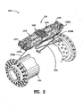
- Fig. 2 is an enlargement 200 of a portion of Fig. 1 illustrating the tubular radial control mechanism 103 and a conduit sensor 101 with magnetic shunt. Also indicated is a spring 201 which is attached to the bottom of one of the conduit sensor devices 101. Each of the conduit sensor devices 101 has two springs 201 affixed thereto. These springs provide the force to open the assembly as shown in Fig. 2 when the radial control mechanism 103 commands the radial movement of the conduit sensor devices 101. Wires/rods 103A, 103B support one conduit sensor device 101 from the tubular radial control mechanism 103.
- Fig. 3 is a schematic perspective view 300 of the conduit sensor device 101 with magnetic shunt. Omitted from the drawings are numerous bolt holes some of which are threaded and some of which are simply passageways for the bolts. Also omitted from the drawings are numerous bolts which reside in the passageways and which interconnect the parts of the invention.
- first backing-bar weldment 301 and the second backing-bar weldment 302 are shown.
- First center roller, 303, and second center roller, 304, are illustrated in Fig. 3 .
- Center rollers 303, 304 protect the conduit sensor device, and, more particularly, the sensors 106 from being damaged in the event that the device 101 is moved radially outwardly with too much force.
- Center rollers 303, 304 include pins (unnumbered) which are affixed in apertures such as aperture 321 illustrated in Fig. 3E .
- a recess 322 in the second backing bar weldment accommodates center roller 303.
- Flat surface 323 of second backing bar weldment 302 is the area in which the sensors 106 reside.
- Fig. 3E is a schematic perspective view 300E of the second backing bar weldment 302 of the conduit sensor with magnetic shunt.
- the magnetic shunt is not illustrated in Fig. 3E .
- flat interior face 320 of the second backing bar weldment 302 is illustrated.
- the first magnet rotor assembly 991 resides in housing 326 in the second backing-bar weldment.
- Slot 324 resides in face 320 and provides room for sensor wiring.
- First magnet rotor assembly 991 resides substantially at the first end of the device.
- Housing 326 is shown as a cylindrical aperture in the second backing bar weldment 302 in Fig. 3E .
- Arrow 327 is illustrated in Fig.
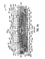
- FIG. 3E is a schematic cross-sectional view 600 taken along the line 6-6 of Fig. 3A .
- passageway 331 extends from the first end of the second backing bar weldment to the second end thereof and houses propulsion shaft 550 therein.
- First backing bar weldment 301 is reciprocally shaped with respect to second backing bar weldment 302.
- the first backing bar weldment 301 includes reciprocally shaped passageways and reciprocally shaped features described in connection with the second backing bar weldment 302.
- backing bar weldment 301 includes a flat interior face which abuts the flat interior face 320 of the second backing bar weldment 302.
- first backing bar weldment 301 includes a recess which is the reciprocal of recess 324 which allows room for wiring when mounted flushly with respect to the second backing bar weldment 302 and affixed to the second backing bar weldment 302.
- First backing bar weldment 301 includes a passageway for housing magnet drive shaft 401 and the passageway is reciprocal to passageway 331 (which houses propulsion shaft 550) and dimensionally the same as passageway 331.
- the first backing bar weldment 301 includes reciprocally shaped recesses corresponding to recesses 329, 330 to permit space for the propulsion motor 620A and the shunt motor 698.
- Shunt motor 698 is supported by a motor support 630 viewed in Figs. 6 , 6B and 9 .
- Motor support 630 is affixed to base plate 311.
- a recessed surface 324 which allows space for wiring from the sensors 106 through the conduit sensor with magnetic shunt 101.
- Fig. 3F is another schematic perspective view 300F of the second backing bar weldment 302 of the conduit sensor with magnetic shunt illustrating some of the features of the second backing bar weldment 302 in more detail. Recesses 329, 330 are illustrated well in Fig. 3F . Slot 328 is illustrated but performs no function, the same being a remnant of the process of manufacturing the second backing bar weldment.
- Fig. 3G is an end view 300G of the second backing bar weldment 302 of the conduit sensor 101 with magnetic shunt illustrating cylindrical housing 326 in the second backing bar weldment 302 and passageway 331. Cylindrically shaped housing 326 terminates in an end surface 326E.
- a circular opening 326C resides in end surface 326E and supports the rotor end 590 as illustrated in Figs. 5 , 5A and 5B .
- Cylindrically shaped housing 326 is typical of cylindrically shaped housing 327 illustrated in Figs. 5 , 5A and 5B and is typical of cylindrically shaped housings 426,427 in the first backing bar weldment 301.
- Passageway 331 extends through the second backing bar weldment 302 and houses the propulsion shaft 550 as illustrated in Figs. 5 , 5A , 5B , 10 and 10A .
- first end gear box half 305 and first end gear box half 306 are illustrated in Fig. 3 and combine to form the first end gear box which is fixed to the first and second backing bar weldments 301, 302.
- Gear box half 306 is fixed to gear box half 305, second backing-bar weldment 302 and end plate 309.
- gear box 305 is fixed to gear box half 306, first backing-bar weldment 301 and end plate 309.
- second end gear box half 307 and second end gear box half 308 combine to form the second end gear box which is fixed to the second end.
- Gear box half 308 is fixed to gear box half 307, second backing-bar weldment 302 and end plate 310.
- gear box 308 is fixed to gear box 307, first backing-bar weldment 301 and end plate 310.
- first backing-bar weldment 301 and second backing-bar weldment 302 are fixed together.
- Wheel wells 305A, 306A, 307A, 308A are illustrated in Fig. 3 and provide room for wheels 107, 107A, 108, 108A to rotate.
- First end bottom plate 309, second end bottom plate 310, and base plate 311 are illustrated in Fig. 3 .
- Base plate 311 extends from the first end 105 to the second end 104 and wraps around the end plates 309, 310.
- First end gear box, 305, 306, and, second end gear box 307, 308 are affixed to base plate 311.
- Fig. 3A is a schematic top view 300A of the conduit sensor device with magnetic shunt 101.
- Fig. 3B is a schematic side view 300B of the conduit sensor with magnetic shunt.
- Base plate 311 includes a first end portion 311A which wraps around the first end bottom plate 309.
- Base plate 311A also includes a second end portion 311 B which wraps around the second end bottom plate 310.
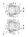
- Fig. 3C is a schematic first end view 300C of the conduit sensor with magnetic shunt.
- First end access port 340 in end 311A of base plate 311 allows adjustment of a thrust bearing for the magnet drive shaft.
- Fig. 3D is a schematic second end view 300D of conduit sensor with magnetic shunt.
- Second end access port 341 in end 311B of base plate 311 allows adjustment of a thrust bearing for the magnet drive shaft (shunt shaft) 401.
- Fig. 3H is a schematic perspective view 300H of the first end gear box half 306 of the conduit sensor with magnetic shunt illustrating bearing well 306A, semi-circular shunt gear housing 306B, semi-circular drive gear housing 306C, and bearing well 306D.
- Bearing well 306A houses bearing 516. See Figs. 5 and 5A .
- reference numeral 389 indicates a shoulder against which bearing 901 resides. See Fig. 9 wherein shaft bearings 901 and 902 are illustrated.
- the shoulders 306K, 306L, 306M, 306N in gear box half 306 meet adjacent corresponding unnumbered shoulders in gear box half 305 illustrated in Fig. 3J.
- Fig. 3J is a schematic perspective view 300J of the first end gear box half 305 of the first end of the conduit sensor device with magnetic shunt.
- FIG. 3J illustrates the semi-cylindrical shunt gear housing 305B and semi-cylindrical drive gear housing 305C.
- Housings 306B, 305B reside adjacent each other and define the shunt worm 612 housing.
- Housings 306C, 305C reside adjacent each other and define propulsion worm 605 housings.
- Slot 305S supports bearing 416 which supports worm 402 mounted on shaft 401.
- Shoulder 305F defines the opening 305D in which drive gear 680 resides.
- Fig. 3K is a schematic perspective view 300K of the first half 305 of the gear box of the first end of the conduit sensor device with magnetic shunt. Shoulder 305H defines seat 305L in which drive shaft bearing 902 resides. See Figs.
- Shoulder 305J defines another diameter in the first half of gear box 305 and reference numeral 305W is the bearing well for bearing 412. See Figs. 4 and 4A .
- Reference numeral 305E indicates the end of the opening which begins with bearing well 305A.
- Reference numeral 305 indicates the passageway for the wheel drive shaft.
- Reference numeral 305R indicates the opening for shunt shaft 401 and worm 402 in gear box half 305.
- vertical slot 340S receives pin 415S of partial cylinder 402C and prevents rotation of the partial cylinder 402C with respect to the first half 305 of the gear box. It is necessary to restrain rotation of the partial cylinder 402C so as to enable adjustment of thrust bearing 402B.
- Figs. 7A and 7C illustrate the partial cylinder 402C in cross-section.
- Magnet drive shaft 401 includes an end portion 401 F which engages thrust bearing 402B.
- Bearing 402B is threadablyadjusted as threaded stud 402N is turned by a suitable tool such as a screw drive or hex headed wrench which mates with grip 402G of the threaded stud 402N.
- Threaded stud 402N includes a curved surface 419C which engages bearing 402B.
- Partial cylinder 402C includes a stepped bore 402R therethrough. Bore 402R has a relatively larger diametrical section which houses thrust bearing 402B. Bore 402R also includes a relatively smaller diametrical threaded section 402T which interengages threaded stud 402N.
- Figs. 7A and 7E illustrate the partial cylinder 403C in cross-section.
- Magnet drive shaft 401 includes an end portion 401S which engages thrust bearing 402B.
- Bearing 402B is threadably adjusted as threaded stud 403N is turned by a suitable tool such as a screw drive or hex headed wrench which mates with grip 403G of the threaded stud 403N.
- Threaded stud 403N includes a curved surface 420C which engages bearing 403B.
- Partial cylinder 403C includes a stepped bore 403R therethrough. Bore 403R has a relatively larger diametrical section which houses thrust bearing 403B. Bore 403R also includes a relatively smaller diametrical threaded section 403T which interengages threaded stud 403N.
- Fig. 7F is a top view 700 F of partial cylinder 402C which provides thrust bearing support for the magnet drive shaft 401.
- Fig. 7G is an end view 700G of the partial cylinder 402C which provides thrust bearing support for the magnet drive shaft.
- Partial cylinder 403C has identical characteristics and, as such, is not separately described.
- Surface 402Z is flat and provides room for gear 608 as illustrated in Figs. 9 and 9A . Also see Figs. 7B and 7D.
- Fig. 7D illustrates the partial cylinder 403C and flat surface 403Z.
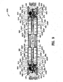
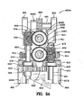
- Fig. 9 is a schematic top view 900 of the conduit sensor with magnetic shunt with the backing bar weldments and the gear boxes removed illustrating the first magnet rotor assembly, second magnet rotor assembly, third magnet rotor assembly and fourth magnet rotor assembly.
- Fig. 9A is a schematic bottom view 900A of the first end of Fig. 9 .
- access ports 340, 341 enable adjustment of the partial cylinders 402, 403 by rotating threaded studs, 402N, 403N clockwise in bores 402T, 403T forcing the partial cylinders outwardly into engagement with the ends 311A, 311 B.
- the threaded studs 402N, 403N may be adjusted at the same time so that approximately the same amount of adjustment may occur on the first and second ends of magnet drive shaft 401.
- the shaft 401 must be positionally supported equally from both the first and second ends. Loctite may be used to secure the threaded connection against vibration. Alternatively, if left handed threaded are used in the bores and on the adjusting threaded nuts, the adjustment may be made by turning the threaded studs counterclockwise. Pin 415S is guided in vertical slot 340S and prohibits rotation of partial cylinder 402C so that it may be adjusted into engagement with end 311A of the base plate 311. At the second end of the device, pin 418S is guided in vertical slot 341S prohibiting rotation of partial cylinder 403C so that it may be adjusted into engagement with end 311B of base plate 311.
- bearing seat 306L supports upper bearing 610 for shunt shaft 611 and shunt worm drive 612.
- Upper bearing 610 supports drive shaft 611.
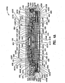
- Vertical shunt worm 612 is affixed to drive shaft 611 by pin 613 as illustrated in Fig. 6A .
- Vertical shunt worm 612 and vertical drive worm 614 include slots therein as best viewed in Fig. 6A .
- Fig. 6 is a schematic cross-sectional view 600 taken along the line 6-6 of Fig. 3A .
- Fig. 6A is an enlargement 600A of the first end portion 601 of the conduit sensor and magnetic shunt device.
- Vertical shunt worm 612 is restrained by shoulder 306K against upward movement.
- bearing 609A is supported by shoulder 309S of bottom plate 309. Similarly, bearing 609 is supported by shoulder 399S of bottom plate 309.
- Spacer 615 resides between bearing 609A and shunt worm wheel 614.
- Spacer 615A resides between vertical shunt worm 612 and upper bearing 610.
- Shunt worm wheel 614 is driven by shaft driven worm 402 as illustrated in Figs. 4 and 4A .
- Worm wheel 614, drive shaft 611, and vertical shunt worm 612 are affixed to each other by pin 613 and, thus, all three components 614, 611, 612 rotate together.
- spacer 617 resides between bearing 609 and drive worm wheel 608.
- Spacer 617A resides between vertical drive worm 605 and upper bearing 603.
- Drive worm wheel 608 is driven by shaft driven worm 558 as illustrated in Figs. 5 , 5A , 9 , 9A , and 9C .
- Worm wheel 608, vertical drive shaft 604, and vertical shunt drive 605 are affixed to each other by pin 606 and, thus, all three components 608, 604, 605 rotate together.
- propulsion motor 620A drives output shaft gear 620 which;.in turn, drives spur gear 555 mounted on the propulsion drive shaft 555.
- Worm 558 is affixed to propulsion drive shaft 550 and rotates therewith.
- Worm wheel 558 is affixed to propulsion drive shaft 550 and as drive shaft 550 rotates, worm wheel 558 rotates, drive worm wheel 608 rotates, and, vertical drive worm 605 rotates driving helical gear 680.
- Rotation of helical gear 680 by drive worm 605 causes rotation of wheels 107, 107A which propel the conduit sensor device 101. Operation of the propulsion drive system is explained in greater detail hereinbelow.
- shaft 550 also drives worm wheel 551 located at the second end of the device.
- worm wheel 551 rotates
- drive worm wheel 644 rotates
- vertical worm 643 rotates driving helical gear 682.
- Rotation of helical gear 682 by vertical drive worm 643 causes rotation of wheels 108, 108A which propel the conduit service device 101.
- Fig. 9 is a schematic top view 900 of the conduit sensor device with backing bar weldments 301, 302 and the gear boxes removed 305, 306, 307, 308.
- Helical gears 414, 514 are viewed in Fig. 9 and 9C .
- the top view is taken from the direction of the pipe (not shown in Fig. 9 ) radially inwardly.
- Magnet rotor assemblies 991, 992, 993, 994 are illustrated without the backing bar weldments 301, 302 which house the magnet rotor assemblies.
- Backing bar weldments 301, 302 are magnetically conductive enabling the magnetic field to pass freely therethrough depending on the orientation of the magnets of the magnet rotor assemblies.
- the first end of the conduit sensor device is the left end when viewing Figs.
- FIG. 9A a schematic bottom view of the first end of Fig. 9 , to view the propulsion motor output gear 620A and the propulsion shaft 550 with spur gear 555 mounted thereto.
- the second end of the conduit sensor device is the right end when viewing Figs. 9 , 9B and 9D , the end having magnet rotors assemblies 993, 994 and the gearing system 403, 404, 408, 548, 551, 635, 636, 643, 644, 682 proximate those rotor assemblies.
- Fig. 9B a schematic bottom view of the second illustrating shunt motor shaft output gear 631 driving spur gear 404 mounted on shunt shaft 401.
- first magnet rotor assembly 991 includes pins 525P, 526P, 527P, 528P which are press-fit through corresponding unnumbered holes in the top portion 525T and bottom portion 525B.
- Magnet rotor assembly 992 includes pins 421P, 422P, 423P, 424P which are press-fit through corresponding unnumbered holes in the top portion 421T and bottom portion 421B.
- Pins 525P, 526P, 527P, 528P are illustrated well in Fig. 9C as are pins 421P, 422P, 423P, 424P.
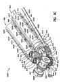
- Fig. 9C is a schematic perspective view 900C of the first end of Fig. 9 illustrating the gear drive system 402, 414, 514, 555, 558; 605, 608, 612, 614, 620, 680 of the first end of the conduit sensor device together with the first end magnet rotor assemblies 991, 992. Also see Fig. 9A to view gears 555, 620.
- First magnet rotor assembly 991 includes permanent magnets 525, 526, 527 and 528 locked together by first rotor shaft end 515 proximate the gear drive system, top portion 525T of the rotor assembly, bottom portion of the rotor assembly and the rotor shaft end 590 distally located with respect to the gear drive system.
- First magnet rotor assembly 991 is housed in cylindrical housing 326 of second backing bar weldment 302 as illustrated in Figs. 3E , 3F and 5 .
- Third magnet rotor assembly 992 includes permanent magnets 421, 422, 423, and 424 locked together by third rotor shaft end 413 proximate the gear drive system, top portion 421T of the rotor assembly, bottom portion 421 B of the rotor assembly and the rotor shaft end 411 distally located with respect to the gear drive system.
- Third magnet rotor assembly 992 is housed in cylindrical housing 426 of first backing bar weldment 301 as illustrated in Figs. 4 and 4A . Still referring to Fig.
- the north poles 525N, 526N, 527N, 528N of the magnets of first magnet rotor assembly 991 are oriented facing upwardly (toward the pipe to be inspected) and, similarly, the north poles 421 N, 422N, 423N and 424N of the magnets of third magnet rotor assembly 992 are oriented facing upwardly.
- the south poles 525S, 526S, 527S, 528S of the magnets of first magnet rotor assembly 991 are oriented facing downwardly.
- the south poles of 421S, 422S, 423S and 424S of the magnets of third magnet rotor assembly 992 are oriented facing downwardly.
- Reference is made to Figs. 5 and 5A to view the south poles 525S, 526S, 527S, 528S of the magnets of first magnet rotor assembly 991.
- Fig. 9A is a bottom schematic view 900A of the first end of Fig. 9 illustrating the gearing system, first magnet rotor assembly 991, and third magnet rotor assembly 992. Bottom 421B of third magnet rotor assembly 992 and bottom 525B of first magnet rotor system 991 are illustrated in Fig. 9A .
- Propulsion motor support 616 is affixed to the base plate 311 and supports centrally located propulsion motor 620A.
- Propulsion motor driven spur gear 620 drives shaft spur gear 555.
- Shaft spur gear 555 includes an integral collar with a set screw therein for affixation to propulsion drive shaft 550.
- Helical gear 514 which is coupled to and drives first magnet rotor assembly 991 is illustrated mounted on first rotor shaft end 515 proximate the gear drive system.
- Third helical gear 414 which is coupled to and drives third magnet rotor assembly 992 is illustrated mounted on the third rotor shaft end 413 proximate the gear drive system.
- Bearings 516, 412 support the magnet rotor assemblies 991, 992, as they are mounted in gear box halves, 306, 305 respectively.
- third magnet rotor assembly 992 is illustrated with bearing 412 mounted in bearing seat 305W of gear box half 305 and fourth magnet rotor assembly 994 is illustrated with bearing 407 mounted in bearing seat 307X of gear box half 307.
- Fig. 9E is an exploded perspective view 900E of fourth magnet rotor assembly 994 of the second end.
- Fourth magnet rotor assembly 994 is typical of magnet rotor assemblies 991, 992 and 993.
- Fig. 9F is an exploded perspective view 900F of the rotor assemblies 993, 994 of the second end.
- the structure illustrated in Fig. 9E of fourth magnet rotor assembly 994 is repeated in Fig. 9F .
- Fig. 9E is slightly larger and easier to read.
- fourth magnet rotor assembly 994 is illustrated wherein rotor shaft end 470 proximate the second end gear system is shown in an exploded perspective.
- Rotor shaft end 470 includes retaining slot 471 for magnet 437, another retaining slot 472 for magnet 437, a circumferentially shaped lip 473, a shaft portion 474 which includes at least two diameters, and, one portion of the shaft 474 includes a locking flat portion 475.
- Flat portion 475 engages a reciprocally shaped flat portion 476 in the collar of helical gear 408.
- the top portion 434T and the bottom portion 434B of the fourth magnet rotor assembly 994 includes a semi-circumferential 471C lip which fits into the circumferentially shaped lip 473 of the rotor shaft end 470.
- Fourth magnet rotor assembly 994 includes magnets 434, 435, 436, 437 secured between a top 434T and a bottom 434B portion.
- Pins 434P, 435P, 436P and 437P are press-fit into corresponding through holes 481, 482, 483, 484 in the top portion 434T and the bottom portion 434B of the assembly.
- Magnets 434, 435, 436, 437 include holes 434H, 435H, 436H and 437H which permit passage of the pins therethrough.
- the north poles of the magnets 434N, 435N, 436N, 437N as well as the south poles of the magnets 434S, 435S, 436S, and 437S are illustrated in Fig. 9E .
- Rotor shaft end 410 distally located with respect to the gear drive system secures the fourth magnet rotor assembly 994 together.
- Snap-ring 410S locks rotor shaft end 410 in place between upper shoulder 434U in the top portion 434T and the lower shoulder 434L in the bottom portion 434B.
- Rotor shaft 410 includes a cylindrical end portion which resides in backing bar weldment 301 as illustrated in Figs. 4 and 4A .
- Circular opening 410D is larger than the diameter of end 410 and supports fourth magnet rotor assembly 994.
- Each magnet rotor assembly includes a bearing.
- One such bearing 407 is illustrated in Fig. 9E which resides in bearing seat 307X of gear box half 307 and supports the magnet rotor assembly 994. See Figs. 4 and 4A .
- Fig. 9F is an exploded perspective view 900F of the rotor assemblies 993, 994 of the second end.
- the second magnet rotor assembly 993 is illustrated wherein rotor shaft end 549 proximate the second end gear system is shown in exploded perspective.
- Rotor shaft end 549 includes retaining slot 571 for magnet 533, another retaining slot 572 for magnet 533, a circurnferentially shaped lip 573, a shaft portion 574 which includes at least two diameters, and, one portion of the shaft 574 includes a locking flat portion 575.
- Flat portion 575 engages a reciprocally shaped flat portion 576 in the collar of helical gear 548.
- the top portion 530T and the bottom portion 530B of the second magnet rotor assembly 993 includes a semi-circumferential 571C lip which fits into the circumferentially shaped lip 573 of the rotor shaft end 549.
- Second magnet rotor assembly 993 includes magnets 530, 531, 532, 533 secured between a top portion 530T and a bottom portion 530B.
- Pins 530P, 531P, 532P and 533P are press-fit into corresponding through holes 581, 582, 583, 584 in the top portion 530T and the bottom portion 530B of the assembly.
- Magnets 530, 531, 532, 533 include holes 530H, 531 H, 532H and 533H which permit passage of the pins therethrough.
- the north poles of the magnets 530N, 531 N, 532N, 533N as well as the south poles of the magnets 530S, 531S, 532S, and 533S are illustrated in Fig.
- Rotor shaft end 491 distally located with respect to the gear drive system secures the second magnet rotor assembly 993 together.
- Snap-ring 491 S locks rotor shaft end 491 axially in place between upper shoulder 530U in the top portion 530T and the lower shoulder 530L in the bottom portion 530B.
- Rotor shaft 591 includes a cylindrical end portion which resides in backing bar weldment 302 as illustrated in Figs. 5 and 5A .
- Circular opening 591D is larger than the diameter of end 591 and supports third magnet rotor assembly 993.
- Each magnet rotor assembly includes a bearing.
- One such bearing 547 is illustrated in Fig. 9F which resides in bearing seat 308X of gear box half 308 and supports the magnet rotor assembly 993.
- Gear box halves 305, 306 are connected together and house the gear systems illustrated in Figs. 6 , 6A , 9 , 9A , and 9C .
- the gear boxes are secured to each other, to first and second backing bar weldments 301, 302, to bottom plate 309 and to the first end of base plate 311A by screws and/or other attachment means.
- Gear box halves 308, 307 are connected together and house the gear systems illustrated in Figs. 6 , 6B , 9 , 9B , and 9D . As stated previously in regard to the gear box halves 306, 305, the gear box halves 308, 307 are similarly secured to each other, to first and second backing bar weldments 301, 302, to bottom plate 310 and to the second end of base plate 311B by screws and/or other attachment means.
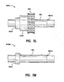
- Fig. 3L is a schematic plan view 300L of the wheel propulsion drive shaft 681 of the first end together with the worm wheel/worm drive gear 680.
- Drive worm gear 680 includes an integral collar 680F which is affixed to the drive shaft 681.
- Fig. 3M is a schematic plan view 300M of the wheel propulsion drive shaft 681 of the first end wherein shoulders 681S, 681H restrain movement of bearings 901, 902. Bearings 901, 902 are illustrated in Figs. 9 , 9A and 9C .
- Fig. 3N is a schematic perspective view 300N of the bottom plate 309 of the first end of conduit sensor device with magnetic shunt.
- Slot 309A in first end gear box bottom plate 309 houses shunt shaft 401 and worm 402 affixed thereto.
- Slot 309B in first end gear box bottom plate 309 houses propulsion shaft 550 and worm 558 affixed thereto.
- Slot 309B is adjacent slot 306S in gear box half 306. Together slots 309B and 306S form a housing/passageway for the propulsion shaft 550 and worm 558.
- Slot 309A is adjacent slot 305S in gear box half 305 and these together form a housing/passageway for shunt shaft 401 and worm 402.
- shoulder 309S supports lower bearing 609A for shunt worm wheel 614 which drives vertical shunt worm 612.
- Shoulder 399S supports lower bearing 609 for drive worm wheel 608 which drives vertical drive worm 605.
- Shoulder 309G extends to cylindrical wall 309W.
- Cylindrical wall 309W in base plate 309 provides room for the rotation of shunt worm wheel 614 as it is diametrically larger than the shunt worm wheel 614.
- Shoulder 309H extends to cylindrical wall 309C.
- Cylindrical wall 309C in base plate 309 provides room for the rotation of drive worm wheel 608 as it is diametrically larger than the drive worm wheel 608.
- Fig. 3O is another schematic perspective view 300O of the bottom plate 309 of the first end of conduit sensor device with magnetic shunt illustrating the same features just described.
- Fig. 9D is a schematic perspective view 900D of the second end of Fig. 9 .
- Fig. 9B is a schematic bottom view 900B of the second end of Fig. 9 .
- Fig. 6B is an enlargement 600B of a portion of Fig. 6 .
- a bearing seat supports upper bearing 637.
- Shunt shaft 638 and shunt worm drive 636 are supported by bearings 637, 633.
- Upper bearing 640 supports drive shaft 639.
- Vertical shunt worm 643 is affixed to drive shaft 639 by pin 642 as illustrated in Fig. 6B .
- Vertical shunt worm wheel 635 and vertical drive worm 636 include slots therein as best viewed in Fig. 6B .
- Vertical drive worm 643 is restrained by a shoulder in gear box 602 against upward movement.
- bearing 633 is supported by a shoulder of bottom plate 310.
- bearing 646 is supported by a shoulder of bottom plate 310.
- Spacer 634 resides between bearing 633 and shunt worm wheel 635.
- Spacer 634A resides between vertical shunt worm 636 and upper bearing 637.
- Shunt worm wheel 635 is driven by shaft driven worm 403 as illustrated in Figs. 4 and 4A .
- Worm wheel 635, drive shaft 638, and vertical shunt worm 636 are affixed to each other by pin 641 and, thus, all three components 635, 638, 636 rotate together.
- shunt motor 698 includes shaft 698S which drives output shaft gear 631 which, in turn, drives spur gear 406 affixed to shunt shaft 401. See Figs. 4 and 4A to view spur gear 406.
- Worm 403 is affixed to shunt shaft 401 and as shunt shaft 401 rotates, worm 403 rotates, shunt worm wheel 635 rotates, and, vertical shunt worm 636 rotates driving helical gears 408, 548.
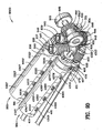
- Fig. 9D is a schematic perspective view 900D of the second end of Fig. 9 illustrating the gear drive system 403, 404, 408, 548, 551, 635, 636, 643, 644, 682 of the second end of the conduit sensor device 101 together with the magnet rotor assemblies 993, 994 residing substantially at the second end of the device. Also see Fig. 9B .
- Second magnet rotor assembly 993 includes permanent magnets 530, 531, 532, 533 locked together by second end rotor shaft end 549 proximate the gear drive system, top portion 530T of the rotor assembly, bottom portion of the rotor assembly and the rotor shaft end 591 distally located with respect to the gear drive system.
- Fourth magnet rotor assembly 994 includes permanent magnets 434, 435, 436, 437 locked together by second rotor shaft end 470 proximate the gear drive system, top portion 434T of the rotor assembly, bottom portion 434B of the rotor assembly and the rotor shaft end 410 distally located with respect to the gear drive system. Still referring to Fig. 9D , the south poles 530S, 531S, 532S, 533S of the magnets of second magnet rotor assembly 993 are oriented facing upwardly (toward the pipe to be inspected) and, similarly, the south poles 434S, 435S, 436S and 437S of the magnets of fourth magnet rotor assembly 994 are oriented facing upwardly.
- the north poles 530N, 531N, 532N, 533N of the magnets of second magnet rotor assembly 993 are oriented facing downwardly.
- the north poles 434N, 435N, 436N and 437N of the magnets of fourth magnet rotor assembly 994 are oriented facing downwardly.
- Reference is made to Figs. 5 and 5A to view the north poles 530N, 531 N, 532N, 533N of the magnets of second magnet rotor assembly 993.
- Fig. 9B is a bottom schematic view 900B of the second end of Fig. 9 illustrating the gearing system, second magnet rotor assembly 993, and fourth magnet rotor assembly 994. Bottom 434B of fourth magnet rotor assembly 994 and bottom 530B of second magnet rotor system 993 are illustrated in Fig. 9B .
- Shunt motor support 630 is affixed to the base plate 311 and supports centrally located shunt motor 698.
- Shunt motor driven spur gear 631 drives shaft spur gear 404.
- Shaft spur gear 404 includes an integral collar with a set screw therein for affixation to shunt shaft 401.
- Helical gear 548 which drives second magnet rotor assembly 993 is illustrated and is mounted on second end rotor shaft 549 proximate the gear drive system.
- Fourth helical gear 408 which drives fourth magnet rotor assembly 994 is illustrated and is mounted on the second end rotor shaft proximate the gear drive system. See Fig. 9F .
- Bearings 547, 407 support the magnet rotor assemblies 993, 994, as they are mounted in gear box halves, 307, 308 respectively.
- fourth magnet rotor assembly 994 is illustrated with bearing 407 mounted in bearing seat 307X of gear box half 307.
- second magnet rotor assembly 993 is illustrated with bearing 547 mounted in bearing seat 308X of gear box half 308.
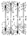
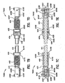
- Fig. 7 is a plan view 700 of magnet drive shaft 401, first end worm 402, spur gear 404 affixed to shaft and second end worm 403.
- Bearings 416, 406 support shaft 401 as best viewed in Figs. 4 and 4A .
- Snap rings 416S, 417S restrain bearing 416 against axial movement on shaft 401.
- Bearing 416 resides in gear box half 305 and bottom plate 309.
- Bearing 406 resides in gear box half 307 and bottom plate 310.
- Fig. 4 is cross-sectional view 400 taken along the line 4-4 of Fig. 3A .
- Line 4-4 is taken along the centerline of magnetic shunt shaft 401.
- Fig. 4A is a cross-sectional view 400A taken along the line 4-4 of Fig.
- First end worm 402 is restrained in place by shoulder 402S and pin 415.
- Pin 415 extends through worm 402 and shaft 401.
- Pin 415 prevents rotation of worm 402 with respect to shaft 401.
- Pin 415 is press-fit into a hole in shaft 401.
- Pin 415 passes through worm 402 and restrains worm 402 against axial movement with respect to shaft 401.
- Shoulder 402S also restrains worm 402 against axial movement.
- spur gear 404 includes an integral collar with a set screw 438S for affixing the collar against rotation with respect to magnet drive shaft 401.
- Snap rings 438, 439 secure spur gear 404 axially with respect to shaft 401
- Snap rings 439 and 453S secure bearing 406 against axial movement with respect to shaft 401.
- Second end worm 403 is affixed to magnet drive shaft 401 in the same way that first end worm 402 is affixed to shaft 401.
- Pin 403P is press fit into a hole in shaft 401 and restrains the worm 403 against axial movement along shaft 401.
- Pin 403P extends through worm 403 and shaft 401 and prevents rotation of worm 403 with respect to shaft 401.
- shoulder 403S also restrains movement of second end worm 403 against movement on shaft 401.
- Fig. 7A is a cross-sectional view 700A taken along the lines 7A-7A of Fig. 7 .
- Fig. 7B is an enlargement 700B of the first end portion of Fig. 7 .
- Fig. 7C is a cross-sectional enlargement 700C of the first end portion of Fig. 7 .
- Fig. 7D is an enlargement 700D of the second end portion of Fig. 7 .
- Fig. 7E is a cross-sectional enlargement 700E of the second end portion of Fig. 7 .
- Fig. 8 is a plan view 800 of propulsion drive shaft 550, first end worm 558, spur gear 555 affixed to shaft 550 and second end worm 551.
- First end worm 558 is secured to shaft 550 against rotation with respect to the shaft by pin 557.
- Snap ring 559 secures the worm 558 against leftward movement along shaft 550.
- Pin 557 resides in slot 557S illustrated in Fig. 8A .
- Snap rings 556S, 561S secure bearing 560 axially in place on shaft 550.
- Snap rings 561S, 562S secure spur gear 555 axially on propulsion drive shaft 550.
- Set screw 597 secures the spur gear 555 on shaft 550.
- Bearings 554S, 553S secure bearing 553 axially on shaft 550.
- Bearings 560, 553 support shaft 550.
- Bearing 560 is mounted in gear box half 306 and bottom plate 309.
- Bearing 560 is supported by surface 309K in the bottom plate and by surface 306S in gear box half 306.
- Bearing 553 is mounted in gear box half 308 and bottom plate 310. See Fig. 5 .
- FIG. 8A is a cross-sectional view 800A taken along the lines 8A-8A of Fig. 8 .
- Fig. 8B is an enlargement 800B of the first end portion of Fig. 8 .
- Fig. 8C is a cross-sectional enlargement 800C of the first end portion of Fig. 8 .
- Fig. 8D is an enlargement 800D of the second end portion of Fig. 8 .
- Fig. 8E is a cross-sectional enlargement 800E of the second end portion of Fig. 8 .
- Fig. 4 is cross-sectional view 400 taken along the line 4-4 of Fig. 3A .
- Fig. 4A is a cross-sectional view 400A taken along the line 4-4 of Fig. 3A .
- Line 4-4 of Fig. 3A is not coincident with the centerline of magnet rotor assemblies 993, 994.
- Line 4-4 is taken along the centerline of the shunt shaft 401.
- Shunt shaft 401 resides slightly inwardly of the centerline of magnet rotor assemblies 993,994.
- Shunt shaft 401 is sometimes referred to herein as the magnet drive shaft.
- Fig. 4 illustrates the magnet rotor assemblies 992, 994 in their home or normal position.
- the magnets of third magnet rotor assembly 992 are oriented such that the north poles 421N, 422N, 423N, 424N of the magnets 421, 422, 423, 424 are oriented facing upwardly.
- the magnets of fourth magnet rotor assembly 994 are oriented such that the south poles 434S, 435S, 436S, 437S are oriented facing upwardly.
- Fig. 4A wherein magnetic field 450 is illustrated for the normal position of magnet rotor assemblies 992, 994.
- Pipe 499 is illustrated with field lines 450 passing therethrough.
- wheels 107, 108 are illustrated in engagement with pipe 499.
- FIGs. 4 and 4A illustrate the magnetic field 450 generated for the second and fourth magnet rotor assemblies.
- the magnetic field generated 450A for the first and third magnet rotor assemblies is illustrated in Fig. 5A .
- shunt shaft 401 is illustrated in cross-section. Sometimes herein shunt shaft 401 is referred to as magnet shaft 401.
- Fig. 4A also illustrated worms 402, 403 and shaft bearings 416, 406.
- Magnet rotor assemblies 992, 994 are illustrated within cylindrical housings 426, 427 in first backing bar weldment 301.
- Cylindrical opening 411 D in backing bar weldment 301 is illustrated with rotor end 411 slip-fitted therein so as to permit rotation of rotor end 411 with respect to the cylindrical opening 411D.
- Rotor assemblies 992,994 are substantially cylindrically-shaped and have a diameter slightly smaller than cylindrical housings 426, 427.
- spur gear 404 affixed to shunt shaft 401 by snap rings 438, 439 and a set screw 438.
- Figs. 7, 7A , 7B, 7C, 7D and 7E illustrate the shunt shaft 401, worms 402, 403 and their mounting on the shunt shaft 401, bearings 406, 416 which support the shunt shaft 401, and spur gear 404.
- Spur gear 404 is affixed to shunt shaft 401 and, as such, spur gear 404 rotates with shunt shaft 401.
- Spur gear 404 is driven by shunt motor spur gear 631 as best viewed in Fig. 9B.
- Fig. 9B is a bottom view of the second end of the conduit sensor device.
- Shunt motor spur gear 631 is driven by shunt motor 698 as illustrated in Fig. 6B .
- bearing 416 resides between support 305S in the gear box half 305 and support 309L in bottom plate 309.
- Bearing 406 similarly supports shaft 401 on the second end of the shaft between an unnumbered support in gear box 307 and an unnumbered support in bottom plate 310.
- Shunt shaft 401 rotates worm 402 at the first end of the device and shunt shaft 401 rotates worm 403 at the second end of the device. Worms 402, 403 are right handed.
- Fig. 9G is a schematic perspective view 900G similar to Fig. 9C indicating rotation of the shunt drive shaft 401 in the clockwise direction 950 as defined from the perspective of the first end of the conduit sensor device and also indicating rotation of the propulsion drive shaft 550 in the clockwise direction 951 as defined from the perspective of the first end of the conduit sensor device.
- worm 402 engages right handed worm wheel 614 at the first end of the device.
- Shaft 611 of worm wheel 614 is oriented 90° with respect to shaft 401 of worm 402.
- worm 402 is rotated in clockwise direction 950 as shunt shaft 401 is rotated in a clockwise direction 950 when viewed from the first end of the conduit sensor device as illustrated in Fig. 9C and 9G .
- worm wheel 614 is rotated clockwise 952 when viewed from the perspective above shaft 611.
- Arrow 959 indicates the direction of travel of the helical gear teeth of worm wheel 614 with respect to worm 402.
- Arrow 959 is substantially tangent to worm wheel 614.
- worm wheel 614 is locked to shaft 611 and right handed vertical worm 612.
- Right handed helical gear 514 is in engagement with right handed vertical worm 612.
- Arrow 955 indicates the direction of travel of the helical gear teeth of helical gears 514, 414 with respect to vertical worm 612.
- Arrow 955 is substantially tangent to helical gears 514, 410.
- shaft 611 of vertical worm 612 is rotated clockwise 952A, then helical gear 514 is rotated in the clockwise direction 953 along the shaft of helical gear 514.
- Vertical worm 612 has a helix angle of 10°.
- the first magnet rotor assembly is mounted at 7.5° with respect to horizontal.
- helical gear 514 has a helix angle of 17.5° which equals 10° plus 7.5°. Different mounting angles may be used, different helix angles of the vertical worm may be used and different helix angles of the helical gear may be used.
- right handed helical gear 514 is mounted on a shaft portion of the first rotor shaft end 515. Simultaneously, as shaft 611 of vertical worm 612 is rotated in the clockwise direction viewed from above, then right handed third helical gear 414 is rotated in the counter clockwise direction 954 along the shaft of third helical gear 414.
- Vertical worm 612 has a helix angle of 10°.
- the second magnet rotor assembly is mounted at 7.5° with respect to horizontal. Therefore, third helical gear 414 has a helix angle of 2.5° which equals 10° minus 7.5°. See Fig. 9G wherein the 7.5° angle is illustrated. See Figs. 9C , 9G and 4A .
- right handed third helical gear 414 is mounted on a shaft portion of the third rotor shaft end 413.
- First magnet rotor assembly 991 is affixed to first rotor shaft end 515 and rotates therewith and first rotor shaft end 515 is affixed to first helical gear 514 and rotates therewith.
- Third magnet rotor assembly 992 is affixed to third rotor shaft end 413 and rotates therewith and third rotor shaft 413 is affixed to third helical gear 414 and rotates therewith.
- Fig. 9I is a schematic perspective view 900I of Fig. 9D indicating rotation of the shunt drive shaft 401 in the clockwise direction 950 as defined from the perspective of the first end of the conduit sensor device and also indicating rotation of the propulsion drive shaft 550 in the clockwise direction 951 as defined from the perspective of the first end of the conduit sensor device.
- Worm 403 engages right handed worm 635 at the second end of the conduit sensor device. See Fig. 9D and 9I .
- Shaft 638 of worm 636 is oriented 90° with respect to shaft 401 of worm 403.
- Arrow 968 indicates the direction of travel of the teeth of helical worm wheel 635 with respect to helical worm 403.
- Arrow 968 is substantially tangent to worm wheel 635.
- Arrow 969 indicates the direction of travel of the teeth of helical gears 408, 548 with respect to vertical helical worm 636.
- Arrow 969 is substantially tangent with respect to second helical gear 548 and third helical gear 408.
- Worm wheel 635 is locked to shaft 638 and right handed vertical worm 636.
- Right handed fourth helical gear 408 is in engagement with right handed vertical worm 636.
- As shaft 638 of vertical worm 636 is rotated clockwise 965A, then fourth helical gear 408 is rotated in the clockwise direction 966 along the shaft of fourth helical gear 408.
- Vertical worm 636 has a helix angle of 10°.
- the fourth magnet rotor assembly is mounted at 7.5° with respect to horizontal.
- fourth helical gear 408 has a helix angle of 17.5° which equals 10° plus 7.5°.
- Right handed fourth helical gear is mounted on a shaft portion of the second rotor shaft end 470.
- Worm 636 engages second helical gear 548.
- Second helical gear 548 is rotated in the counter clockwise direction 967 along the shaft of second helical gear 548.
- Vertical worm 636 has a helix angle of 10°.
- the third magnet rotor assembly is mounted at 7.5° with respect to horizontal as illustrated in Fig. 9I . Therefore, second helical gear 548 has a helix angle of 2.5° which equals 10° minus 7.5°.
- Right handed second helical gear 548 is mounted on a shaft portion of the second rotor shaft end 549.
- Fourth magnet rotor assembly 994 is affixed to second rotor shaft end 470 and rotates therewith and second rotor shaft 470 is affixed to fourth helical gear 408 and rotates therewith.
- Second magnet rotor assembly 993 is affixed to second rotor shaft end 549 and rotates therewith and second rotor shaft end 549 is affixed to second helical gear 548 and rotates therewith.
- Rotation of the shunt shaft 401 in the counter clockwise direction from the perspective of the first end is now described. Reaction of the gearing system which drives the magnet rotor assemblies 991, 992, 993, 994 is now described as well in connection with the counter clockwise rotation of shunt shaft 401.
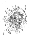
- Fig. 9H is a schematic perspective view 900H similar to Fig. 9C indicating rotation of the shunt drive shaft 401 in the counter clockwise direction 970 as defined from the perspective of the first end of the conduit sensor device and also indicating rotation of the propulsion drive shaft 550 in the counter clockwise direction 971 as defined from the perspective of the first end of the conduit sensor device.
- shunt shaft 401 is rotated in the opposite direction, namely, counter clockwise 970 as indicated by arrow 970 when viewed from the first end of the conduit sensor device as illustrated in Figs. 9C and 9H , then worm wheel 614 rotates in a counter clockwise direction as indicated by arrow 972 when viewed from above shaft 611.
- vertical worm 612 rotates counter clockwise as indicated by arrow 972A
- first helical gear 514 rotates counter clockwise as indicated by arrow 973
- third helical gear 414 rotates clockwise as indicated by arrow 974.
- Fig. 9J is a schematic perspective view 900J similar to Fig. 9D indicating rotation of the shunt drive shaft 401 in the counter clockwise 970 direction as defined from the perspective of the first end of the conduit sensor device and also indicating rotation of the propulsion drive shaft 550 in the counter clockwise 971 direction as defined from the perspective of the first end of the conduit sensor device.
- Fig. 9J illustrates the gearing system and magnet rotor assemblies 993, 994 of the second end of the device.
- worm wheel 635 rotates in the counter clockwise 975 direction when viewed above shaft 638
- vertical worm 636 rotates in the counter clockwise 975A direction since worm 636 is locked to shaft 638 and worm wheel 635.
- shaft 401 is rotated counter clockwise 970 as defined
- worm wheel 635 rotates counter clockwise 975
- fourth helical gear 408 rotates counter clockwise 976
- second helical gear 548 rotates clockwise 978.
- Arrow 979 indicates the direction of travel of worm wheel 635 with respect to worm 403. Arrow 979 is substantially tangent to helical gear 408, 548. Arrow 980 indicates the direction of travel of worm wheel 644 with respect to worm 551. Arrow 980 is substantially tangent to worm wheel 644.
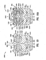
- Fig. 10 is a cross-sectional view 1000 taken along the lines 10-10 of Fig. 3 .
- Fig. 10 illustrates the rotor assemblies 993, 994 in the normal or home position. In the normal or home position, the magnetic field 450 is strongest.
- Figs. 4A and 5A illustrate the magnetic fields 450, 450A at their maximum extent.
- Fig. 4A illustrates rotor assemblies 992, 994 and
- Fig. 5A illustrates magnet rotor assemblies 991, 993.
- Fig. 9 clearly illustrates the rotor assemblies 991, 992, 993, 994 in their home position.
- Fig. 4A illustrates rotor assemblies 992,994 in their home positions.
- Magnets 421,422,423,424 of third magnet rotor assembly 992 are illustrated with their north poles 421 N, 422N, 423N, 424N oriented facing upwardly toward pipe 499.
- Magnets 434, 435, 436, and 437 of fourth magnet rotor assembly 994 are illustrated with their south poles 434S, 435S, 436S and 437S oriented facing upwardly toward pipe 499.
- Fig. 5A illustrates magnet rotor assemblies 991, 993 in their home position.
- Magnets 525, 526, 527, 528 of rotor assembly 991 are illustrated with their north poles 525N, 526N, 527N, 528N oriented facing upwardly toward pipe 499.
- Magnets 530, 531, 532, 533 of second magnet rotor assembly 993 are illustrated with their south poles 530S, 531S, 532S, 533S oriented facing upwardly.
- Figs. 4A and 5A illustrate magnet rotor assemblies 993, 994 oriented in the same position as Fig. 10.
- Fig. 10 illustrates the top portion 530T and the bottom portion 530B of second magnet rotor assembly 993, as well as magnet 530.
- Second magnet rotor assembly 993 is illustrated residing in cylindrically shaped housing 327 in backing bar weldment 302.
- the diameter of second magnet rotor assembly 993 is smaller than the diameter of the cylindrically shaped housing 327 such that second magnet assembly 993 rotates without engaging housing 327. Any incidental engagement that might occur is insignificant and does not impede the rotation of the second magnet rotor assembly 993.
- propulsion drive shaft 550 resides within bore or passageway 331 in second backing bar weldment 302. The diameter of propulsion drive shaft 550 is less than the diameter of passageway 331 and, therefore, propulsion drive shaft 550 rotates freely within the passageway 331.
- the shunt shaft 401 resides within passageway 377.
- Passageway 377 extends from the first end of the backing bar weldment 301 to the second end of the backing bar weldment 301 as illustrated in Fig. 4A .
- the diameter of the shunt shaft 401 is smaller than the diameter of the passageway 377.
- Fig. 10A is a cross-sectional view 1000A taken along the lines 10-10 of Fig. 3 , with shunt shaft 401 rotated counter clockwise and with the rotor assemblies 993, 994 of the second end rotated 90° to the position where the magnetic fields are cancelled.
- shaft 401 is rotated counter clockwise as defined
- worm wheel 635 rotates counter clockwise
- fourth helical gear 408 rotates counter clockwise
- second helical gear 548 rotates clockwise. See Fig. 9J .
- magnet rotor assemblies 993, 994 and magnets 530, 434 are positioned in their second position as illustrated in Fig. 10A with sufficient rotation of shaft 401.
- Shaft 401 is driven by the shunt motor 698 which drives shaft 698S which drives shunt shaft output gear 631. See Fig. 6B .
- Shunt shaft output gear 631 engages shunt shaft mounted gear 404.
- Shunt motor 698 may be a single direction motor or the motor may be bidirectional.
- Shunt motor 698 may be a stepper motor. Motor control is necessary to control the positioning of the magnet rotor assemblies, and, hence the strength of the magnetic field between the first end and the second end of the device.
- a specific number of revolutions of the shunt drive shaft 401 equates to specific number of revolutions of the vertical worms 612, 636.
- a specific number of revolutions of the vertical worm 612 equates to a specific number of revolutions, or fractional part thereof, of first helical gear 514 and third helical gear 414. Further, a specific number of revolutions of the vertical worm 636 equates to a specific number of revolutions, or fractional part thereof, of second helical gear 548 and fourth helical gear 408. Therefore, control of the shunt shaft 401 dictates control and position of the magnet rotor assemblies 991, 992, 993, 994. The control system is responsible for rotating the magnets between the first position, 0° rotation as shown in Figs. 9 , 9C , 9D , 10 , and 11 to the second position illustrated in Figs. 5B , 10A , and 11A , 90° rotation based on counter clockwise rotation of shunt shaft 401.
- FIG. 10A illustrates the position of the magnet rotor assemblies 993, 994 as a result of counter clockwise rotation of shunt shaft 401 to the shunt position or cancellation position.
- the position of the magnet rotor assemblies 991, 992, 993, 994 is dependent on the positioning of shunt shaft 401 which drives shaft-mounted worms 402, 403.
- the magnetic field 1001, 1002 of the second magnet rotor assembly 993 is shown in Fig. 10A .
- the magnetic field 1003, 1004 of the fourth magnet rotor assembly 994 is shown in Fig. 10A . In the position illustrated in Fig.
- the magnet rotor assemblies do not create a magnetic field in pipe 499; rather, the magnetic fields of the magnet rotor assemblies 993, 994 are shunted meaning there is no magnetic field between the first and second-ends of the conduit sensor device as illustrated in Figs. 4A and 5A .
- reference numeral 1010 signifies and indicates the rear or rearward portion of the conduit sensor device.
- Reference numeral 1011 signifies and indicates the front or forward portion of the conduit sensor device.
- Reference numeral 1012 signifies and indicates the central portion of the conduit sensor device.
- Fig. 11 is a cross-sectional view 1100 taken along the lines 11-11 of Fig. 3 .
- Fig.11A is a cross-sectional view 1100 taken along the lines 11-11 of Fig. 3 with the rotor assemblies 991, 992 of the first end rotated 90° with shunt shaft 401 rotated counter clockwise. See Figs. 9H and 9J .
- Fig. 11A is a cross-sectional view 1100A taken along the lines 11-11 of Fig. 3 with the rotor assemblies 993,994 of the second end rotated 90° to the position where the magnetic fields are cancelled. Reference is made to Figs. 4A and 5A wherein the field strengths 450, 450A are illustrated at their maximum.
- FIG. 11A illustrates the position of the magnet rotor assemblies 991, 992 as a result of counter clockwise rotation of shunt shaft 401 to the shunt position or cancellation position, for example a 90° rotation of the magnet rotor assemblies.
- the terms "shunt position” and “cancellation position” are also known as the "second position.”
- Figs. 9 , 9C , 9D , 10 , and 11 illustrate the magnet rotor assemblies 991, 992, 993, and 994 in their first positions (0° rotation).
- the magnetic field 1101, 1102 of the second magnet rotor assembly 993 is shown in Fig. 10A .
- the magnetic field 1103, 1104 of the fourth magnet rotor assembly 994 is shown in Fig. 11A .
- the magnet rotor assemblies do not create a magnetic field in pipe 499; rather, the magnetic fields of the magnet rotor assemblies 991, 991 are shunted meaning there is no magnetic field between the first and second ends of the conduit sensor device as illustrated in Figs. 4A and 5A .
- the magnet rotor assemblies 991, 992,993, 994 include top portions and bottom portions as described herein wherein the top and bottom portions, magnets and pins together with the rotor ends form the assemblies.
- the top and bottom portions of each of the magnet rotor assemblies 991, 992, 993, 994 are ferromagnetic.
- the first and second backing bar weldments 301, 302 are ferromagnetic.
- First and second backing bar weldments 301, 302 are made of 1008 steel capable of carrying a higher magnetic field than typical 1018 steel.
- Figs. 4A and 5A are schematic cross-sectional views of the conduit sensor device with magnetic field lines 450 illustrated.
- the invention is not limited in any way by the size of the magnets or the magnet rotor assemblies.
- FIGs. 4A and 5A the home position of the rotatable magnets is illustrated.
- the home position of the rotatable magnets is also shown in Figs. 4 and 5 .
- the pipe wall 499 is illustrated with a thickness and the magnetic fields 450, 450A are illustrated passing entirely through the wall of the pipe 499.
- Fig. 5 is a cross-sectional view 500 taken along the lines 5-5 of Fig. 3A .
- Line 5-5 is taken along the centerline of the propulsion drive shaft 550.
- Fig. 5A is a cross-sectional view 500A taken along the lines 5-5 of Fig. 3A with a pipe in the view.
- Fig. 5B is a cross-sectional view 500B taken along the lines 5-5 of Fig. 3A with rotor assemblies rotated 90°. No polarities of the magnets are noted in Fig. 5B as the magnets are shown in cross section as are the pins which hold the magnets in place. The pins are press-fitted into the top and bottom portions of the magnet rotor assembly. In the position illustrated in Fig.
- first magnet rotor assembly 991 and second magnet rotor assembly 993 there is no magnetic field between first magnet rotor assembly 991 and second magnet rotor assembly 993 as the magnetic fields have been shunted (cancelled) as illustrated in Figs. 10A and 11 , and, as such there is no magnetic field shown in Fig. 5B .
- Fig. 5 illustrates the magnet rotor assemblies 991, 993 in their home or normal position. In the normal position the magnets of rotor assembly 991 are oriented such that the north poles 525N, 526N, 527N, 528N of the magnets 525, 526, 527, 528 are oriented facing upwardly.
- propulsion drive shaft 550 is illustrated in cross-section.
- Fig. 5A also illustrated worms 558,551 and shaft bearings 560, 553.
- Magnet rotor assemblies 991,993 are illustrated within cylindrical housings 326, 327 in second backing bar weldment 302.
- Cylindrical opening 590D in backing bar weldment 302 is illustrated with rotor end 590 slip-fitted therein so as to permit rotation of rotor end 590 with respect to the cylindrical opening 590D.
- cylindrical opening 591D in backing bar weldment 302 is illustrated with rotor end 591D slip-fitted therein so as to permit rotation of rotor end 591D with respect to cylindrical opening 591D.
- Rotor assemblies 991, 993 are substantially cylindrically-shaped and have a diameter slightly smaller than cylindrical housings 326, 327 in which they reside.
- the magnetic field 450A generated by the first magnet rotor assembly 991 and the second magnet rotor assembly 993 is illustrated in Fig. 5A .
- the magnetic field 450 generated by the second magnet rotor assembly 992 and the fourth magnet rotor assembly 994 is illustrated in Fig. 4A .
- Figs. 5 and 5A the entire length of propulsion drive shaft 550 is viewed as is spur gear 555 affixed to propulsion drive shaft 550 by snap rings 561S, 562S and a set screw 527.
- Figs. 8, 8A , 8B, 8C, 8D and 8E illustrate the propulsion drive shaft 550, worms 558, 551 and their mounting on the propulsion drive shaft 550, bearings 560, 553 which support the shunt shaft 550, and spur gear 555.
- Spur gear 555 is driven by propulsion motor spur gear 620 as best viewed in Fig. 9A.
- Fig. 9A is a bottom view of the first end of the conduit sensor device.
- the propulsion drive motor spur gear 620 is driven by the propulsion motor 620A as illustrated in Fig. 6A .
- bearing 560 resides between support 306S in the gear box half 306 and support 309K in bottom plate 309.
- Bearing 553 similarly supports shaft 550 on the second end thereof between an unnumbered support in gear box 308 and an unnumbered support in bottom plate 310.
- a process according to the present invention for modifying a magnetic field of a conduit sensor device is disclosed.
- the conduit sensor is in proximity to a ferromagnetic conduit.
- the steps of the process include: driving a shunt shaft having first and second worms affixed thereto and rotating therewith; rotating, using the first worm, a first worm wheel and a first vertical worm affixed thereto; rotating, using the first vertical worm, a first helical gear and a first magnet rotor assembly affixed to the first helical gear; rotating, using the second worm, a second worm wheel and a second vertical worm affixed thereto; and, rotating, using the second vertical worm, a second helical gear and a second magnet rotor assembly affixed to the second helical gear.
- the process further includes rotating, using the first vertical worm, a third helical gear and a third magnet rotor assembly affixed to the third helical gear; and, rotating, using the second vertical worm, a fourth helical gear and a fourth magnet rotor assembly affixed to the fourth helical gear.
- the steps of rotating the first, second, third and fourth magnet assemblies may include rotating the magnet assemblies from a first position wherein a magnetic field exists between the first magnet assembly and the second magnet assembly and from a first position wherein a magnetic field exists between the third magnet assembly and the fourth magnet assembly to a second position wherein no magnetic field exists between the first magnet assembly and the second magnet assembly and wherein no magnetic field exists between the third magnet assembly and the fourth magnet assembly.
- the shunt shaft may be rotated bidirectionally.
- the first, second, third and fourth magnet assemblies may be rotated 90° to their second position.
- Each of the magnet rotor assemblies includes a plurality of magnets and the magnet rotor assemblies are housed and supported in first and second backing bar weldments. According to the process, the rotation of the first and third magnet rotor assemblies residing at a first end of the device and the rotation of the second and fourth magnet rotor assemblies residing at a second end of the device is performed synchronously.
- the steps of rotating the first, second, third and fourth magnet assemblies may include rotating the magnet assemblies less than 90°: from a first position wherein a maximum strength magnetic field exists between the first magnet assembly and the second magnet assembly; and, from a first position wherein a maximum strength magnetic field exists between the third magnet assembly and the fourth magnet assembly, to an intermediate position wherein a lower strength magnetic field exists between the first magnet assembly and the second magnet assembly and wherein a lower strength magnetic field exists between the third magnet assembly and the fourth magnet assembly.
- right handed worms 558, 551 are mounted on shaft 550. On the first end, worm 558 engages worm wheel 608; on the second end, worm 551 engages worm wheel 644.
- Fig. 9G is a schematic perspective view 900G of Fig. 9C indicating rotation of the propulsion drive shaft 550 in the clockwise direction 951 as defined and viewed from the perspective of the first end of the conduit sensor device.
- worm wheel 608 rotates counter clockwise 956 from the perspective of Fig. 9 .
- Arrow 960 indicates the direction of travel of the worm wheel 608 with respect to worm 558 when shaft 550 and worm 558 are rotated clockwise 951 as defined herein.
- Arrow 960 is substantially tangent to worm 558.
- shaft 550 rotates clockwise 951
- vertical worm 605 rotates counter clockwise 957 from the perspective of Fig. 9 , specifically, from above the first end.
- gear 680 rotates counter clockwise 958 along its shaft as viewed in Figs. 9C and 9G from right to left and in Fig. 6A .
- gear 680 is affixed to wheel shaft 681, and as wheels 107, 107A are affixed to wheel shaft 681 and rotate therewith, the conduit sensor device will be propelled rightwardly when viewing Figs. 6 , 6A , 6B and 9 .
- Fig. 9I is a schematic perspective view 900I similar to Fig. 9D indicating rotation of the propulsion drive shaft 550 in the clockwise direction 951 as defined from the perspective of the first end of the conduit sensor device.
- propulsion drive shaft 550 rotates clockwise 951 when viewed from the first end toward the second end, then worm 551 also rotates clockwise 951 as worm 551 is affixed to shaft 550.
- Worm 551 and worm wheel 644 driven by worm 551 are right handed.
- Vertical worm 643 and worm wheel 682 are left handed and these are the only two left handed worm and worm wheel disclosed here. All other worms and worm wheels are right handed.
- Vertical worm 643 and worm wheel 682 are left handed so that worm wheels 680, 682 rotate in the same direction. Other gearing arrangements and combinations may be used.
- worm wheel 644 rotates counter clockwise 961 when viewed from above the conduit sensor device as illustrated in Figs. 9 , 9D ad 9I.
- Fig. 9B a bottom view of the second end of the conduit sensor device, reference is made to worm 551 in meshed engagement with worm wheel 644.
- worm wheel 644 rotates clockwise when worm 551 is rotating clockwise with respect to the first end of the device.
- Arrow 964 in Fig. 9I indicates the direction of travel of worm wheel 644 with respect to worm 551.
- Arrow 964 is substantially tangent to worm wheel 644.
- Fig. 9H is a schematic perspective view 900H similar to Fig. 9C indicating rotation of the shunt drive shaft 401 in the counter clockwise direction 971 as defined from the perspective of the first end of the conduit sensor device and also indicating rotation of the propulsion drive shaft 550 in the counter clockwise 971 direction as defined from the perspective of the first end of the conduit sensor device.
- worm wheel 608 rotates clockwise 985 from the perspective of Fig. 9 .
- shaft 550 rotates counter clockwise 971
- worm 605 rotates clockwise 987 from the perspective of Fig. 9 .
- Arrow 986 indicates the direction of travel of worm wheel 608 with respect to worm 558.
- Arrow 986 is substantially tangent to worm wheel 608.
- Reference numeral 987A indicates the direction of travel of the teeth of worm wheel 680 with respect to worm 605. Arrow 987 is substantially tangent to worm wheel 680.
- worm wheel 680 is affixed to wheel shaft 681, and as wheels 107, 107A are affixed to wheel shaft 681 and rotate therewith, the conduit sensor device will be propelled leftwardly when viewing Figs. 6 , 6A , 6B and 9 .
- Fig. 9J is a schematic perspective view 900J similar to Fig. 9D indicating rotation of the propulsion drive shaft 550 in the counter clockwise direction as defined from the perspective of the first end of the conduit sensor device.
- worm 551 if propulsion drive shaft 550 rotates counter clockwise 971 when viewed from the first end toward the second end, then worm 551 also rotates counter clockwise 971 as worm 551 is affixed to shaft 550. As worm 551 rotates counter clockwise 971 then worm wheel 644 rotates clockwise 981 when viewed from above the conduit sensor device as illustrated in Figs. 9 , 9D and 9J .
- Fig. 9B a bottom view of the second end of the conduit sensor device, reference is made to worm 551 in meshed engagement with worm wheel 644. From the perspective of Fig. 9B , worm wheel 644 rotates counter clockwise.
- worm wheel 644 rotates clockwise from the perspective of Fig. 9
- vertical worm 643 rotates clockwise 982 from the perspective of Fig. 9
- left-handed worm wheel 682 rotates clockwise 983 along its shaft, as viewed from left to right in Figs. 9D and 9J .
- Arrow 984 indicates the direction of travel of worm wheel 682 with respect to vertical left-handed worm 643.
- Arrow 984A indicating the direction of travel of helical gears 408, 548 with respect to worm 636.
- a method outside the scope of the present invention and for operating a conduit sensor device which propels the device within a conduit includes the steps of: rotating a propulsion shaft having first and second worms affixed thereto and rotating therewith; rotating, using the first worm, a first worm wheel and a first vertical worm affixed thereto; rotating, using the first vertical worm, a first drive wheel worm having a first drive wheel affixed thereto; rotating, using the second worm, a second drive worm wheel and a second vertical worm affixed thereto; and, rotating, using the second vertical worm, a second drive worm wheel having a second drive wheel affixed thereto. Also, a step of: synchronizing the first and second drive wheels.
Landscapes
- Chemical & Material Sciences (AREA)
- Analytical Chemistry (AREA)
- General Health & Medical Sciences (AREA)
- Physics & Mathematics (AREA)
- Health & Medical Sciences (AREA)
- Life Sciences & Earth Sciences (AREA)
- Chemical Kinetics & Catalysis (AREA)
- Biochemistry (AREA)
- Electrochemistry (AREA)
- General Physics & Mathematics (AREA)
- Immunology (AREA)
- Pathology (AREA)
- Measurement Of Length, Angles, Or The Like Using Electric Or Magnetic Means (AREA)
- Dynamo-Electric Clutches, Dynamo-Electric Brakes (AREA)
- Investigating Or Analyzing Materials By The Use Of Magnetic Means (AREA)
Description
- The invention is in the field of pipeline inspection devices/sensors, especially conduit sensor device and a process for modifying a magnetic field of a conduit sensor device
-
US- 6,762,602 proposed a "device, e.g. an inspection pig, for inspecting conduits made from ferromagnetic materials, such as pipelines, for faults, cracks, corrosion or the like, comprising at least one pulling element, a supporting structure of variable circumference, disposed on the pulling element and comprising substantially radially disposed supporting arms each of which is pivotable about axes disposed perpendicular to the longitudinal central axis of the pulling element, and several permanent magnets disposed at the circumference of the supporting structure for generating a magnetic filed, and with sensors." Further,US- 6,762,602 states, pertinent part: "[f]or strengthening or weakening the magnetic field generated by the permanent magnet in dependence on the circumference of the supporting structure or in dependence on the lateral separation between the permanent magnets. The permanent magnets are associated with further magnets having a magnetic field which can be varied in direction or strength. In an embodiment, the further magnets associated with the permanent magnets are permanent magnets, wherein the direction of their magnetic field can be changed by turning using an electric or mechanical actuator. In another embodiment coils are used as magnets, which can be supplied with a variable current." See, the Abstract ofUS- 6,762,6021 - The diametrical size of the conduit, the thickness of the conduit, and the lateral separation of the poles of the magnet are factors in the performance of the sensor. Sensors such as piezo-electric, electro-acoustic, and electromagnetic sensors such as Hall, stray field and eddy current sensors may be used.
-
US- 6,762,602 does not effectively shunt the magnetic field produced by the poles through use of respective rotatable magnets. Additionally, the drive system of the rotatable magnets disclosed inUS-6,762,602 involves a mechanical system using springs and a toothed wheel with a selected diameter and selected number of teeth. The diameter and the number of teeth may be changed to control the rotatable magnet. Further, a spring is necessary for each of the rotatable magnets and adjustment of those magnets in a coordinated manner is difficult, and, therefore, control of the magnetic field is difficult. One of the poles in theUS- 6,762,602 may be adjusted differently than the other pole because the springs and toothed gears cannot be matched or properly controlled. Spring constants and biasing of the rotatable magnets inUS- 6,762,602 may not be equal and, hence, contribution of each of the poles to the magnetic field may be different. - Alternatively,
US- 6,762,602 further discloses an electrically driven toothed wheel which is controlled by appropriate electric, electronic or mechanical sensor element for determining the lateral separation between the parallelogram supports. However, there is no disclosure inUS- 6,762,602 as to the coordinated operation and control of the rotatable magnets. - A more effective magnetic shunt which substantially completely reduces the magnetic field associated with a plurality of inner peripheral sensors is needed for unpiggable pipe lines. So-called unpiggable pipe lines require substantial cancellation of the magnetic field caused by permanent magnets used in conduit sensors placed in proximity to the conduit/pipe line. When the field created by the permanent magnets is substantially cancelled, the sensor may be drawn more easily through the pipeline as the sensor and its supporting structure are no longer magnetically attracted to the walls of the conduit/pipeline.
-
EP 2 407 778 - Use of a conduit sensor device requires application of north and south poles in proximity to the conduit/pipe line wall which creates a magnetic field extending into the wall of the conduit/pipe line. Control of the magnetic field which enters the conduit/pipe line is necessary for the correct interpretation of data obtained from the sensors. Sensors, such as a Hall effect sensors, measure anomalies such as cracks and deterioration of the structure of the conduit/pipeline when a magnetic field is imparted in the conduit/pipeline. Control of the magnetic field imparted in the conduit/pipeline is important as it allows correct interpretation of the data generated from the sensors. As such, a conduit sensor device which accurately controls the magnetic field in the conduit/pipeline wall is needed.
- For this purpose, the conduit sensor device of the invention comprises the features of
claims 1 and the Method of the invention comprises the features of claim 12. Preferred embodiments of the invention are characterized in the dependent claims. - The conduit sensor disclosed herein controls the magnetic field as required to obtain accurate data and to allow movement through a pipeline or conduit. Additionally, the conduit sensor disclosed herein is self-propelled in two directions, forwardly and rearwardly.
- There is a plurality of conduit sensor devices arranged on the inner periphery of the pipeline/conduit which form an inspection pig. Each conduit sensor device includes several sensors associated therewith and each device covers a sector of the pipeline/conduit. Any number of conduit sensors may be used to form an inspection pig.
- Each conduit sensor device includes a magnetic shunt device. The magnetic shunt device is used to effectively turn off the magnetic field. The inspection pig is propelled through the pipeline/conduit by drive means which are disclosed herein. Each of the conduit sensor devices propels the conduit sensor device through the pipeline to be inspected. Further, and importantly, the magnetic shunt device enables the curtailment of the magnetic field in the pipeline/conduit making movement of the inspection pig within the interior of the pipeline/conduit and through valves and other obstructions inside the pipeline easier.
- Further, the magnetic shunt device imparts an appropriately adjustable magnetic field into the pipeline/conduit as dictated by the operation of the inspection pig and/or as required for other reasons such as comparison of the data presently being taken against previously taken data for a given conduit/pipeline.
- A conduit sensor device comprising a first end portion and a second end portion is disclosed. A first magnet rotor assembly resides proximate the first end portion of the device and is rotatable between first and second positions. A second magnet rotor assembly resides proximate the second end portion of the device and is rotatable between first and second positions. The first position of the first magnet rotor assembly in combination with the first position of the second magnet rotor assembly creates the maximum strength magnetic field. The second position of the second magnet rotor assembly in combination with the second position of the second magnet rotor assembly effectively completely shunts the magnetic field rendering no magnetic field. The first magnetic rotor assembly and the second magnetic rotor assembly move in unison under the control of a shunt motor. In other words if the orientation of the first magnet rotor assembly is rotated 45° then the orientation of the second magnet rotor assembly is rotated 45° in the same direction when viewed from the first end of the device.
- According to the present invention, a first and third rotor assembly reside proximate the first end of the conduit sensor device and a second and fourth rotor assembly reside proximate the second end of the conduit sensor device. The first and third rotor assemblies proximate the first end are rotated 90° such that the top portions thereof face each other at the conclusion of the 90° rotation canceling the magnetic field when the shunt shaft is rotated counter clockwise with respect to the first end. Similarly, the second and fourth rotor assemblies proximate the second end are rotated 90° such that the top portions thereof face away from each other at the conclusion of the 90° rotation canceling the magnetic field when the shunt shaft is rotated counter clockwise with respect to the first end.
- The first magnet rotor assembly includes a first plurality of magnets axially arranged about a first axis, the first magnet rotor assembly includes a first top portion and a first bottom portion, and, the first top and bottom portions secure the first plurality of magnets within the first magnet rotor assembly. The second magnet rotor assembly includes a second plurality of magnets axially arranged about a second axis, the second magnet rotor assembly includes a second top portion and a second bottom portion, and, the second top and bottom portions secure the second plurality of magnets within the second magnet rotor assembly.
- The first position of the first magnet rotor assembly orients the north pole of each of the first plurality of magnets radially outwardly. The first position of the second magnet rotor assembly orients the south pole of each of the second plurality of magnets radially outwardly. The second position of the first magnet rotor assembly orients the north pole of each of the first plurality of magnets at an angle of 90° with respect to the first position; and, the second position of the second magnet rotor assembly orients the north pole of each of the second plurality of magnets at an angle of 90° with respect to said first position. The direction of rotation depends on the direction of rotation of the shunt shaft with respect to the first end.
- A worm drive is a gear arrangement in which a worm meshes with a worm wheel sometimes referred to as a worm gear. The terms "worm wheel" and "worm gear" are synonymous. The worm drives the worm wheel. The worm wheel is similar in appearance to a spur gear. A worm is essentially a gear in the form of a screw.
- The conduit sensor device includes a first drive mechanism for rotating the first magnet rotor assembly from the first position to the second position and a second drive mechanism for rotating the second magnet rotor assembly from the first position to the second position. The first drive mechanism includes a first vertical shunt worm for rotating the first magnet rotor assembly. The second drive mechanism includes a second vertical shunt worm for rotating the second magnet rotor assembly. A shunt shaft extends between the first end portion of the device to the second end portion of the device. A first shunt shaft worm and a second shunt shaft worm are affixed to the shunt shaft. A first shunt worm wheel engages the first shunt shaft worm and a second shunt worm wheel engages the second shunt shaft worm. The first shunt worm wheel is engaged with the first vertical shunt worm wheel and is rotatable therewith. The second shunt worm wheel is engaged with the second vertical shunt worm wheel and is rotatable therewith.
- A first helical gear is affixed to the first magnet rotor assembly. A second helical gear is affixed to the second magnet rotor assembly. The first helical gear is engaged with the first vertical shunt worm wheel and the second helical gear is engaged with the second vertical shunt worm wheel. The first magnet rotor assembly is rotatable with the first helical gear; and, the second magnet rotor assembly is rotatable with the second helical gear.
- A third magnet rotor assembly residing proximate the first end portion of the device and rotatable between first and second positions is preferably used. A fourth magnet rotor assembly resides proximate the second end portion of the device and is rotatable between first and second positions is preferably used. The third magnet rotor assembly includes a third plurality of magnets axially arranged about a third axis. The third magnet rotor assembly includes a third top portion and a third bottom portion. The third top and bottom portions secure the third plurality of magnets within the third magnet rotor assembly. The fourth magnet rotor assembly includes a fourth plurality of magnets axially arranged about a fourth axis. The fourth magnet rotor assembly includes a fourth top portion and a fourth bottom portion. The fourth top and bottom portions secure the fourth plurality of magnets within the fourth magnet rotor assembly.
- The first position of the third magnet rotor assembly orients the north pole of each of the third plurality of magnets radially outwardly. The first position of the fourth magnet rotor assembly orients the south pole of each of the fourth plurality of magnets radially outwardly. The second position of the third magnet rotor assembly orients the north pole of each of the third plurality of magnets at an angle of 90° with respect to the first position. The second position of the fourth magnet rotor assembly orients the north pole of each of the fourth plurality of magnets at an angle of 90° with respect to said first position. The direction of rotation of the first and third magnet rotor assemblies depends on the direction of rotation of the shunt shaft.
- A third drive mechanism rotates the third magnet rotor assembly from the first position to the second position and a fourth drive mechanism rotates the fourth magnet rotor assembly from the first position to the second position. The third drive mechanism includes the first vertical shunt worm for rotating the third magnet rotor assembly; and, the fourth drive mechanism includes the second vertical shunt worm for rotating the fourth magnet rotor assembly.
- A third helical gear is affixed to the third magnet rotor assembly. The fourth helical gear is affixed to the fourth magnet rotor assembly. The third helical gear is engaged with the first vertical shunt worm. The fourth helical gear is engaged with the second vertical shunt worm. The third magnet rotor assembly is rotatable with the third helical gear; and, the fourth magnet rotor assembly is rotatable with the fourth helical gear.
- The conduit sensor device according to the present invention includes a first end of the device and a second end of the device. A first magnet rotor assembly, a third magnet rotor assembly, a third magnet rotor assembly, and a fourth magnet rotor assembly are disclosed. The first magnet rotor assembly and the second magnet rotor assembly reside at the first end of the device. The second magnet rotor assembly and the fourth magnet rotor assembly reside at the second end of the device. The first and third magnet rotor assemblies are rotationally movable in a range of positions between a first position and a second position at the first end of the device. The third and fourth magnet rotor assemblies are rotationally movable in a range of positions between a first position and a second position at the second end of the device. A magnetic shunt shaft includes first and second ends, the first end of the magnetic shunt shaft resides at the first end of the device and the second end of the magnetic shunt shaft resides at the second end of the device. A first gearbox resides at the first end of the device and a second gearbox resides at the second end of the device. A first worm is affixed to the first end of the magnetic shunt shaft arid a second worm is affixed to the second end of the magnetic shunt shaft. The first gearbox includes: a first wheel worm; a first vertical worm affixed to the first wheel worm; a first helical gear, the first helical gear engages the first vertical worm; and, a third helical gear, the third helical gear engages the first vertical worm gear. The first magnet rotor assembly is affixed to the first helical gear and is rotatable therewith. The third magnet rotor assembly is affixed to the third helical gear and is rotatable therewith. The first worm is affixed to the first end of the magnetic shunt shaft and engages the first wheel worm and drives the first vertical worm affixed to the first wheel worm. The first vertical worm drives the first helical gear and the first magnet rotor assembly in a first rotational direction between first and second positions and the first vertical worm drives the third helical gear and the third magnet rotor assembly in a second rotational direction opposite to the first rotational direction of the first helical gear between first and second positions. The second gearbox includes: a second wheel worm; a second vertical worm affixed to the second wheel worm; a second helical gear, the second helical gear engages the second vertical worm; and, a fourth helical gear, the fourth helical gear engages the second vertical worm. The second magnet rotor assembly is affixed to the second helical gear and is rotatable therewith. The fourth magnet rotor assembly is affixed to the third helical gear and is rotatable therewith. The second worm affixed to the second end of the magnetic shunt shaft engages the second wheel worm and drives the second vertical worm affixed to the second wheel worm. The second vertical worm drives the second helical gear and the second magnet rotor assembly in a first rotational direction between the first and second positions and the second vertical worm drives the fourth helical gear and the fourth magnet rotor assembly in a second rotational direction opposite to the first rotational direction of the second helical gear between the first and second positions. When the first and third magnet rotor assemblies are in the first position and when the second and fourth magnet rotor assemblies are in the first position, a magnetic field of maximum strength is generated between the first and the second magnet rotor assemblies and the third and fourth magnetic rotor assemblies, and, the magnetic field of maximum strength extends into a conduit. When the first and third magnet rotor assemblies are in the second position and when the second and fourth magnet rotor assemblies are in the second position, no magnetic field exists between the first and second magnet rotor assemblies and no magnetic field exists between the third and fourth magnet rotor assemblies. When the first and second magnet rotor assemblies are in a rotational position intermediate the first and second positions, and when the third and fourth magnet rotor assemblies are in a rotational position intermediate the first and second positions, then the strength of the magnetic field between the first and second magnet rotor assemblies is modified according to the rotational positions of said first and second magnet rotor assemblies, and then the strength of the magnetic field between the third and fourth magnet rotor assemblies is modified according to the rotational positions of the second and fourth magnet rotor assemblies.
- The first magnet rotor assembly includes a plurality of magnets and each one of the plurality of magnets includes a north pole and a south pole. The second magnet rotor assembly includes a plurality of magnets and each one of the plurality of magnets includes a north pole and a south pole. The third magnet rotor assembly includes a plurality of magnets and each one of the plurality of magnets includes a north pole and a south pole. The fourth magnet rotor assembly includes a plurality of magnets and each one of the plurality of magnets includes a north pole and a south pole. When the first and third magnet rotor assemblies are in the first position: the south poles of each of the plurality of magnets of the first magnet rotor assembly face downwardly away from the conduit and the north poles of each of the plurality of magnets of the first magnet rotor assembly face upwardly toward the conduit; and, the south poles of each of the plurality of magnets of the third magnet rotor assembly face downwardly away from the conduit and the north poles of each of the plurality of magnets of the third magnet rotor assembly face upwardly toward the conduit. When the second and fourth magnet rotor assemblies are in the first position: the south poles of each of the plurality of magnets of the second magnet rotor assembly face upwardly toward the conduit and the north poles of each of the plurality of magnets of the second magnet rotor assembly face downwardly away from the conduit; and, the south poles of each of the plurality of magnets of the fourth magnet rotor assembly face upwardly toward the conduit and the north poles of each of the plurality of magnets of the fourth magnet rotor assembly face downwardly away from the conduit.
- Further advantages, features and potential applications of the present invention may be gathered from the description which follows, in conjunction with the embodiments illustrated in the drawings.
- Throughout the description, the claims and the drawings, those terms and associated reference signs will be used as are notable from the enclosed list of reference signs. In the drawings is shown:
- Fig. 1
- a schematic perspective view of a plurality of conduit sensor devices, and, each of the conduit sensor devices includes a plurality of sensors and magnetic shunts;
- Fig. 2
- an enlargement of a portion of
Fig. 1 illustrating the tubular radial control mechanism and a conduit sensor with magnetic shunt; - Fig. 3
- a schematic perspective view of one conduit sensor device with magnetic shunt;
- Fig. 3A
- a schematic top view of the conduit sensor device with magnetic shunt;
- Fig. 3B
- a schematic side view of the conduit sensor device with magnetic shunt;
- Fig. 3C
- a schematic first end view of conduit sensor device with magnetic shunt;
- Fig. 3D
- a schematic second end view of conduit sensor device with magnetic shunt;
- Fig. 3E
- a schematic perspective view of the second backing bar weldment of the conduit sensor device with magnetic shunt;
- Fig. 3F
- another schematic perspective view of the second backing bar weldment of the conduit sensor device with magnetic shunt;
- Fig. 3G
- a schematic end view of the second backing bar weldment of the conduit sensor device with magnetic shunt;
- Fig. 3H
- a schematic perspective view of the second half of the gear box of the first end of the conduit sensor device with magnetic shunt;
- Fig. 31
- another schematic perspective view of the second half of the gear box of the first end of the conduit sensor device with magnetic shunt;
- Fig, 3J
- a schematic perspective view of the first half of the gear box of the first end of the conduit sensor device with magnetic shunt;
- Fig. 3K
- a schematic perspective view of the frst half of the gear box of the first end of the conduit sensor device with magnetic shunt;
- Fig. 3L
- a schematic plan view of the wheel propulsion drive shaft of the first end together with the drive gear;
- Fig. 3M
- a schematic plan view of the wheel propulsion drive shaft of the first end;
- Fig. 3N
- a schematic perspective view of the bottom plate of the first end of conduit sensor device with magnetic shunt;
- Fig. 3O
- another schematic perspective view of the bottom plate of the first end of conduit sensor device with magnetic shunt;
- Fig. 4
- cross-sectional schematic view taken along the line 4-4 of
Fig. 3A ; - Fig.4A
- a cross-sectional schematic view taken along the line 4-4 of
Fig. 3A ; - Fig. 5
- a cross-sectional schematic view taken along the lines 5-5 of
Fig. 3A ; - Fig. 5A
- a cross-sectional schematic view taken along the lines 5-5 of
Fig. 3A with a pipe in the view; - Fig. 5B
- a cross-sectional schematic view taken along the lines 5-5 of
Fig. 3A with rotor assemblies rotated 90°; - Fig. 6
- a cross-sectional schematic view taken along the line 6-6 of
Fig. 3A ; - Fig. 6A
- an enlargement of a portion of
Fig. 6 ; - Fig. 6B
- an enlargement of a portion of
Fig. 6 ; - Fig. 7
- a schematic plan view of the magnet drive shaft, first end worm, spur gear affixed to shaft and second end worm;
- Fig. 7A
- a cross-sectional view taken along the
lines 7A-7A ofFig. 7 ; - Fig. 7B
- an enlargement of the first end portion of
Fig. 7 ; - Fig. 7C
- a cross-sectional enlargement of the first end portion of
Fig. 7 ; - Fig. 7D
- an enlargement of the second end portion of
Fig. 7 ; - Fig. 7E
- a cross-sectional enlargement of the second end portion of
Fig. 7 ; - Fig. 7F
- a top view of partial cylinder which provides thrust bearing support for the magnet drive shaft;
- Fig. 7G
- an end view of the partial cylinder which provides thrust bearing support for the magnet drive shaft;
- Fig. 8
- a schematic plan view of magnet drive shaft, first end worm, spur gear affixed to shaft and second end worm;
- Fig. 8A
- a cross-sectional view taken along the
lines 8A-8A ofFig. 8 ; - Fig. 8B
- an enlargement of the first end portion of
Fig. 8 ; - Fig. 8C
- a cross-sectional enlargement of the first end portion of
Fig. 8 ; - Fig. 8D
- an enlargement of the second end portion of
Fig. 8 ; - Fig. 8E
- a cross-sectional enlargement of the second end portion of
Fig. 8 ; - Fig. 9
- a schematic top view of the conduit sensor with magnetic shunt with the backing bar weldments and the gear boxes removed illustrating the first magnet rotor assembly, second magnet rotor assembly, third magnet rotor assembly and fourth magnet rotor assembly;
- Fig. 9A
- a schematic bottom view of the first end of
Fig. 9 ; - Fig. 9B
- a schematic bottom view of the second end of
Fig. 9 ; - Fig. 9C
- a schematic perspective view of the first end of
Fig. 9 illustrating the first and third magnet rotor assemblies and associated shunt gearing as well as the propulsion system gearing; - Fig. 9D
- a schematic perspective view of the second end of
Fig. 9 illustrating the second and fourth magnet rotor assemblies and associated gearing as well as the propulsion system gearing; - Fig. 9E
- an exploded perspective view of one of the fourth magnet rotor assembly of the second end;
- Fig. 9F
- an exploded perspective view of the second and fourth magnet rotor assemblies of the second end;
- Fig. 9G
- a schematic perspective view similar to
Fig. 9C indicating rotation of the shunt drive shaft in the clockwise direction as defined from the perspective of the first end of the conduit sensor device and also indicating rotation of the propulsion drive shaft in the clockwise direction as defined from the perspective of the first end of the conduit sensor device; - Fig. 9H
- a schematic perspective view similar to
Fig. 9C indicating rotation of the shunt drive shaft in the counter clockwise direction as defined from the perspective of the first end of the conduit sensor device and also indicating rotation of the propulsion drive shaft in the counter clockwise directions as defined from the perspective of the first end of the conduit sensor device; - Fig. 9I
- a schematic perspective view similar to
Fig. 9D indicating rotation of the shunt drive shaft in the clockwise direction as defined from the perspective of the first end of the conduit sensor device and also indicating rotation of the propulsion drive shaft in the clockwise directions as defined from the perspective of the first end of the conduit sensor device; - Fig. 9J
- a schematic perspective view similar to
Fig. 9D indicating rotation of the shunt drive shaft in the counter clockwise direction as defined from the perspective of the first end of the conduit sensor device and also indicating rotation of the propulsion drive shaft in the counter clockwise directions as defined from the perspective of the first end of the conduit sensor device; - Fig. 10
- a schematic cross-sectional view taken along the lines 10-10 of
Fig. 3 ; - Fig. 10A
- a schematic cross-sectional view taken along the lines 10-10 of
Fig. 3 with the rotor assemblies of the second end rotated 90°; - Fig. 11
- a schematic cross-sectional view taken along the lines 11-11 of
Fig. 3 , and - Fig. 11A
- a schematic cross-sectional view taken along the lines 11-11 of
Fig. 3 with the rotor assemblies of the first end rotated 90°. -
Fig. 1 is aschematic perspective view 100 of a plurality ofconduit sensor devices 101, and, each of theconduit sensor devices 101 includes a plurality ofsensors 106 and magnetic shunts.Arrow 101 is illustrated pointing to one conduit sensor with a magnetic shunt therein.Reference numeral 102 is used to denote couplings between the plurality of conduit sensors and battery powereddrive units 109. A tubularradial control mechanism 103 controls wires/rods for extending theconduit sensors 101 radially outwardly and for contracting the conduit sensors radially inwardly.Arrow 104 indicates the second end of one conduit sensor with a magnetic shunt andarrow 105 indicates the first end of one conduit sensor with magnetic shunt.Arrow 106 indicates electronic sensors used to detect anomalies and defects in pipes and conduits.Reference numerals -
Fig. 2 is anenlargement 200 of a portion ofFig. 1 illustrating the tubularradial control mechanism 103 and aconduit sensor 101 with magnetic shunt. Also indicated is aspring 201 which is attached to the bottom of one of theconduit sensor devices 101. Each of theconduit sensor devices 101 has twosprings 201 affixed thereto. These springs provide the force to open the assembly as shown inFig. 2 when theradial control mechanism 103 commands the radial movement of theconduit sensor devices 101. Wires/rods conduit sensor device 101 from the tubularradial control mechanism 103. -
Fig. 3 is aschematic perspective view 300 of theconduit sensor device 101 with magnetic shunt. Omitted from the drawings are numerous bolt holes some of which are threaded and some of which are simply passageways for the bolts. Also omitted from the drawings are numerous bolts which reside in the passageways and which interconnect the parts of the invention. In the central portion of the device, the first backing-bar weldment 301 and the second backing-bar weldment 302 are shown. First center roller, 303, and second center roller, 304, are illustrated inFig. 3 .Center rollers sensors 106 from being damaged in the event that thedevice 101 is moved radially outwardly with too much force.Center rollers aperture 321 illustrated inFig. 3E . Arecess 322 in the second backing bar weldment accommodatescenter roller 303.Flat surface 323 of secondbacking bar weldment 302 is the area in which thesensors 106 reside. -
Fig. 3E is aschematic perspective view 300E of the secondbacking bar weldment 302 of the conduit sensor with magnetic shunt. The magnetic shunt is not illustrated inFig. 3E . Referring toFig. 3E , flatinterior face 320 of the secondbacking bar weldment 302 is illustrated. The firstmagnet rotor assembly 991 resides inhousing 326 in the second backing-bar weldment.Slot 324 resides inface 320 and provides room for sensor wiring. Firstmagnet rotor assembly 991 resides substantially at the first end of the device.Housing 326 is shown as a cylindrical aperture in the secondbacking bar weldment 302 inFig. 3E .Arrow 327 is illustrated inFig. 3E as pointing to another housing for secondmagnet rotor assembly 993. Secondmagnet rotor assembly 993 resides substantially at the second end of the device. Still referring toFig. 3E ,recess 329 provides space for thepropulsion motor 620A as illustrated inFig. 6 .Recess 330 provides space for theshunt motor 698 as illustrated inFig. 6. Fig. 6 is a schematiccross-sectional view 600 taken along the line 6-6 ofFig. 3A . - Referring to
Fig. 3F ,passageway 331 extends from the first end of the second backing bar weldment to the second end thereof and housespropulsion shaft 550 therein. Firstbacking bar weldment 301 is reciprocally shaped with respect to secondbacking bar weldment 302. In other words, the firstbacking bar weldment 301 includes reciprocally shaped passageways and reciprocally shaped features described in connection with the secondbacking bar weldment 302. For instance, backingbar weldment 301 includes a flat interior face which abuts the flatinterior face 320 of the secondbacking bar weldment 302. Similarly, the firstbacking bar weldment 301 includes a recess which is the reciprocal ofrecess 324 which allows room for wiring when mounted flushly with respect to the secondbacking bar weldment 302 and affixed to the secondbacking bar weldment 302. Firstbacking bar weldment 301 includes a passageway for housingmagnet drive shaft 401 and the passageway is reciprocal to passageway 331 (which houses propulsion shaft 550) and dimensionally the same aspassageway 331. Further, the firstbacking bar weldment 301 includes reciprocally shaped recesses corresponding torecesses propulsion motor 620A and theshunt motor 698.Shunt motor 698 is supported by amotor support 630 viewed inFigs. 6 ,6B and9 .Motor support 630 is affixed tobase plate 311. Also illustrated inFig. 3E is a recessedsurface 324 which allows space for wiring from thesensors 106 through the conduit sensor withmagnetic shunt 101. -
Fig. 3F is anotherschematic perspective view 300F of the secondbacking bar weldment 302 of the conduit sensor with magnetic shunt illustrating some of the features of the secondbacking bar weldment 302 in more detail.Recesses Fig. 3F .Slot 328 is illustrated but performs no function, the same being a remnant of the process of manufacturing the second backing bar weldment.Fig. 3G is anend view 300G of the secondbacking bar weldment 302 of theconduit sensor 101 with magnetic shunt illustratingcylindrical housing 326 in the secondbacking bar weldment 302 andpassageway 331. Cylindrically shapedhousing 326 terminates in anend surface 326E. Acircular opening 326C resides inend surface 326E and supports therotor end 590 as illustrated inFigs. 5 ,5A and5B . Cylindrically shapedhousing 326 is typical of cylindrically shapedhousing 327 illustrated inFigs. 5 ,5A and5B and is typical of cylindrically shaped housings 426,427 in the firstbacking bar weldment 301.Passageway 331 extends through the secondbacking bar weldment 302 and houses thepropulsion shaft 550 as illustrated inFigs. 5 ,5A ,5B ,10 and 10A . - Referring back to
Fig. 3 , first endgear box half 305 and first endgear box half 306 are illustrated inFig. 3 and combine to form the first end gear box which is fixed to the first and secondbacking bar weldments Gear box half 306 is fixed togear box half 305, second backing-bar weldment 302 andend plate 309. In the same way,gear box 305 is fixed togear box half 306, first backing-bar weldment 301 andend plate 309. - Referring still to
Fig. 3 , second endgear box half 307 and second endgear box half 308 combine to form the second end gear box which is fixed to the second end.Gear box half 308 is fixed togear box half 307, second backing-bar weldment 302 andend plate 310. In the same way,gear box 308 is fixed togear box 307, first backing-bar weldment 301 andend plate 310. Still additionally, first backing-bar weldment 301 and second backing-bar weldment 302 are fixed together. -
Wheel wells Fig. 3 and provide room forwheels bottom plate 309, secondend bottom plate 310, andbase plate 311 are illustrated inFig. 3 .Base plate 311 extends from thefirst end 105 to thesecond end 104 and wraps around theend plates end gear box base plate 311. -
Fig. 3A is a schematictop view 300A of the conduit sensor device withmagnetic shunt 101.Fig. 3B is aschematic side view 300B of the conduit sensor with magnetic shunt.Base plate 311 includes afirst end portion 311A which wraps around the firstend bottom plate 309.Base plate 311A also includes asecond end portion 311 B which wraps around the secondend bottom plate 310. -
Fig. 3C is a schematicfirst end view 300C of the conduit sensor with magnetic shunt. Firstend access port 340 inend 311A ofbase plate 311 allows adjustment of a thrust bearing for the magnet drive shaft.Fig. 3D is a schematicsecond end view 300D of conduit sensor with magnetic shunt. Secondend access port 341 inend 311B ofbase plate 311 allows adjustment of a thrust bearing for the magnet drive shaft (shunt shaft) 401.Fig. 3H is aschematic perspective view 300H of the first endgear box half 306 of the conduit sensor with magnetic shunt illustrating bearing well 306A, semi-circularshunt gear housing 306B, semi-circulardrive gear housing 306C, and bearing well 306D. Bearing well 306A houses bearing 516. SeeFigs. 5 and5A . - Referring to
Fig. 3H ,reference numeral 389 indicates a shoulder against which bearing 901 resides. SeeFig. 9 whereinshaft bearings Upper shoulder 306K in the semi-circularshunt gear housing 306, limits upper movement ofvertical shunt worm 612. Theshoulders gear box half 306 meet adjacent corresponding unnumbered shoulders ingear box half 305 illustrated inFig. 3J. Fig. 3J is aschematic perspective view 300J of the first endgear box half 305 of the first end of the conduit sensor device with magnetic shunt.Fig. 3J illustrates the semi-cylindricalshunt gear housing 305B and semi-cylindricaldrive gear housing 305C.Housings shunt worm 612 housing.Housings propulsion worm 605 housings.Slot 305S supports bearing 416 which supportsworm 402 mounted onshaft 401.Shoulder 305F defines theopening 305D in which drivegear 680 resides.Fig. 3K is aschematic perspective view 300K of thefirst half 305 of the gear box of the first end of the conduit sensor device with magnetic shunt.Shoulder 305H definesseat 305L in which drive shaft bearing 902 resides. SeeFigs. 9 and9C .Shoulder 305J defines another diameter in the first half ofgear box 305 andreference numeral 305W is the bearing well for bearing 412. SeeFigs. 4 and4A .Reference numeral 305E indicates the end of the opening which begins with bearing well 305A.Reference numeral 305 indicates the passageway for the wheel drive shaft.Reference numeral 305R indicates the opening forshunt shaft 401 andworm 402 ingear box half 305. - Referring to
Figs. 3K ,4 ,4A ,7 ,7A ,7B ,7C ,7F and 7G ,vertical slot 340S receivespin 415S ofpartial cylinder 402C and prevents rotation of thepartial cylinder 402C with respect to thefirst half 305 of the gear box. It is necessary to restrain rotation of thepartial cylinder 402C so as to enable adjustment of thrust bearing 402B. -
Figs. 7A and7C illustrate thepartial cylinder 402C in cross-section.Magnet drive shaft 401 includes anend portion 401 F which engages thrust bearing 402B.Bearing 402B is threadablyadjusted as threadedstud 402N is turned by a suitable tool such as a screw drive or hex headed wrench which mates withgrip 402G of the threadedstud 402N. Threadedstud 402N includes acurved surface 419C which engages bearing 402B.Partial cylinder 402C includes a steppedbore 402R therethrough.Bore 402R has a relatively larger diametrical section which houses thrust bearing 402B. Bore 402R also includes a relatively smaller diametrical threadedsection 402T which interengages threadedstud 402N. -
Figs. 7A and7E illustrate thepartial cylinder 403C in cross-section.Magnet drive shaft 401 includes anend portion 401S which engages thrust bearing 402B.Bearing 402B is threadably adjusted as threadedstud 403N is turned by a suitable tool such as a screw drive or hex headed wrench which mates withgrip 403G of the threadedstud 403N. Threadedstud 403N includes acurved surface 420C which engages bearing 403B.Partial cylinder 403C includes a steppedbore 403R therethrough.Bore 403R has a relatively larger diametrical section which houses thrust bearing 403B. Bore 403R also includes a relatively smaller diametrical threadedsection 403T which interengages threadedstud 403N. -
Fig. 7F is atop view 700 F ofpartial cylinder 402C which provides thrust bearing support for themagnet drive shaft 401.Fig. 7G is anend view 700G of thepartial cylinder 402C which provides thrust bearing support for the magnet drive shaft.Partial cylinder 403C has identical characteristics and, as such, is not separately described.Surface 402Z is flat and provides room forgear 608 as illustrated inFigs. 9 and9A . Also seeFigs. 7B and 7D. Fig. 7D illustrates thepartial cylinder 403C andflat surface 403Z. -
Fig. 9 is a schematictop view 900 of the conduit sensor with magnetic shunt with the backing bar weldments and the gear boxes removed illustrating the first magnet rotor assembly, second magnet rotor assembly, third magnet rotor assembly and fourth magnet rotor assembly.Fig. 9A is aschematic bottom view 900A of the first end ofFig. 9 . - Referring to
Figs. 3C, 3D , and4 ,access ports partial cylinders bores ends studs magnet drive shaft 401. In other words, given the intermeshing ofworms respective worm wheels gear 404 with themotor drive gear 631, theshaft 401 must be positionally supported equally from both the first and second ends. Loctite may be used to secure the threaded connection against vibration. Alternatively, if left handed threaded are used in the bores and on the adjusting threaded nuts, the adjustment may be made by turning the threaded studs counterclockwise.Pin 415S is guided invertical slot 340S and prohibits rotation ofpartial cylinder 402C so that it may be adjusted into engagement withend 311A of thebase plate 311. At the second end of the device,pin 418S is guided invertical slot 341S prohibiting rotation ofpartial cylinder 403C so that it may be adjusted into engagement withend 311B ofbase plate 311. - Referring to
Figs. 3H, 3I ,6 , and6A , bearingseat 306L supportsupper bearing 610 forshunt shaft 611 andshunt worm drive 612.Upper bearing 610 supports driveshaft 611.Vertical shunt worm 612 is affixed to driveshaft 611 bypin 613 as illustrated inFig. 6A .Vertical shunt worm 612 andvertical drive worm 614 include slots therein as best viewed inFig. 6A .Fig. 6 is a schematiccross-sectional view 600 taken along the line 6-6 ofFig. 3A .Fig. 6A is anenlargement 600A of thefirst end portion 601 of the conduit sensor and magnetic shunt device.Vertical shunt worm 612 is restrained byshoulder 306K against upward movement. - Referring to
Fig. 6A , bearing 609A is supported byshoulder 309S ofbottom plate 309. Similarly, bearing 609 is supported byshoulder 399S ofbottom plate 309.Spacer 615 resides betweenbearing 609A and shuntworm wheel 614.Spacer 615A resides betweenvertical shunt worm 612 andupper bearing 610.Shunt worm wheel 614 is driven by shaft drivenworm 402 as illustrated inFigs. 4 and4A .Worm wheel 614,drive shaft 611, andvertical shunt worm 612 are affixed to each other bypin 613 and, thus, all threecomponents - Referring to
Fig. 6A ,spacer 617 resides betweenbearing 609 and driveworm wheel 608.Spacer 617A resides betweenvertical drive worm 605 andupper bearing 603. Driveworm wheel 608 is driven by shaft drivenworm 558 as illustrated inFigs. 5 ,5A ,9 ,9A , and9C .Worm wheel 608,vertical drive shaft 604, andvertical shunt drive 605 are affixed to each other bypin 606 and, thus, all threecomponents - Referring to
Figs. 5A and6A ,propulsion motor 620A drivesoutput shaft gear 620 which;.in turn, drivesspur gear 555 mounted on thepropulsion drive shaft 555.Worm 558 is affixed topropulsion drive shaft 550 and rotates therewith.Worm wheel 558 is affixed topropulsion drive shaft 550 and asdrive shaft 550 rotates,worm wheel 558 rotates, driveworm wheel 608 rotates, and,vertical drive worm 605 rotates drivinghelical gear 680. Rotation ofhelical gear 680 bydrive worm 605 causes rotation ofwheels conduit sensor device 101. Operation of the propulsion drive system is explained in greater detail hereinbelow. - Referring to
Figs. 6B and5A ,shaft 550 also drivesworm wheel 551 located at the second end of the device. Asdrive shaft 550 rotates,worm wheel 551 rotates, driveworm wheel 644 rotates, andvertical worm 643 rotates drivinghelical gear 682. Rotation ofhelical gear 682 byvertical drive worm 643 causes rotation ofwheels conduit service device 101. -
Fig. 9 is a schematictop view 900 of the conduit sensor device withbacking bar weldments Fig. 9 and9C . The top view is taken from the direction of the pipe (not shown inFig. 9 ) radially inwardly.Magnet rotor assemblies backing bar weldments bar weldments Figs. 9 ,9A and9C , the first end havingmagnet rotor assemblies gearing system Fig. 9A , a schematic bottom view of the first end ofFig. 9 , to view the propulsionmotor output gear 620A and thepropulsion shaft 550 withspur gear 555 mounted thereto. - The second end of the conduit sensor device is the right end when viewing
Figs. 9 ,9B and9D , the end havingmagnet rotors assemblies gearing system Fig. 9B , a schematic bottom view of the second illustrating shunt motorshaft output gear 631driving spur gear 404 mounted onshunt shaft 401. - Referring to
Fig. 9 , firstmagnet rotor assembly 991 includespins top portion 525T andbottom portion 525B.Magnet rotor assembly 992 includespins top portion 421T andbottom portion 421B. Pins 525P, 526P, 527P, 528P are illustrated well inFig. 9C as arepins -
Fig. 9C is aschematic perspective view 900C of the first end ofFig. 9 illustrating thegear drive system magnet rotor assemblies Fig. 9A to viewgears magnet rotor assembly 991 includespermanent magnets rotor shaft end 515 proximate the gear drive system,top portion 525T of the rotor assembly, bottom portion of the rotor assembly and therotor shaft end 590 distally located with respect to the gear drive system. Firstmagnet rotor assembly 991 is housed incylindrical housing 326 of secondbacking bar weldment 302 as illustrated inFigs. 3E ,3F and5 . Thirdmagnet rotor assembly 992 includespermanent magnets rotor shaft end 413 proximate the gear drive system,top portion 421T of the rotor assembly,bottom portion 421 B of the rotor assembly and therotor shaft end 411 distally located with respect to the gear drive system. Thirdmagnet rotor assembly 992 is housed incylindrical housing 426 of firstbacking bar weldment 301 as illustrated inFigs. 4 and4A . Still referring toFig. 9C , thenorth poles magnet rotor assembly 991 are oriented facing upwardly (toward the pipe to be inspected) and, similarly, thenorth poles magnet rotor assembly 992 are oriented facing upwardly. Thesouth poles magnet rotor assembly 991 are oriented facing downwardly. The south poles of 421S, 422S, 423S and 424S of the magnets of thirdmagnet rotor assembly 992 are oriented facing downwardly. Reference is made toFigs. 5 and5A , to view thesouth poles magnet rotor assembly 991. -
Fig. 9A is a bottomschematic view 900A of the first end ofFig. 9 illustrating the gearing system, firstmagnet rotor assembly 991, and thirdmagnet rotor assembly 992.Bottom 421B of thirdmagnet rotor assembly 992 and bottom 525B of firstmagnet rotor system 991 are illustrated inFig. 9A .Propulsion motor support 616 is affixed to thebase plate 311 and supports centrally locatedpropulsion motor 620A. Propulsion motor drivenspur gear 620 drivesshaft spur gear 555.Shaft spur gear 555 includes an integral collar with a set screw therein for affixation topropulsion drive shaft 550.Helical gear 514 which is coupled to and drives firstmagnet rotor assembly 991 is illustrated mounted on firstrotor shaft end 515 proximate the gear drive system. Thirdhelical gear 414 which is coupled to and drives thirdmagnet rotor assembly 992 is illustrated mounted on the thirdrotor shaft end 413 proximate the gear drive system.Bearings magnet rotor assemblies Figs. 4 , and4A , thirdmagnet rotor assembly 992 is illustrated with bearing 412 mounted in bearingseat 305W ofgear box half 305 and fourthmagnet rotor assembly 994 is illustrated with bearing 407 mounted in bearingseat 307X ofgear box half 307. -
Fig. 9E is an explodedperspective view 900E of fourthmagnet rotor assembly 994 of the second end. Fourthmagnet rotor assembly 994 is typical ofmagnet rotor assemblies Fig. 9F is an explodedperspective view 900F of therotor assemblies Fig. 9E of fourthmagnet rotor assembly 994 is repeated inFig. 9F .Fig. 9E is slightly larger and easier to read. Referring toFig. 9E , fourthmagnet rotor assembly 994 is illustrated whereinrotor shaft end 470 proximate the second end gear system is shown in an exploded perspective.Rotor shaft end 470 includes retainingslot 471 formagnet 437, another retainingslot 472 formagnet 437, a circumferentially shapedlip 473, ashaft portion 474 which includes at least two diameters, and, one portion of theshaft 474 includes a lockingflat portion 475.Flat portion 475 engages a reciprocally shapedflat portion 476 in the collar ofhelical gear 408. Thetop portion 434T and thebottom portion 434B of the fourthmagnet rotor assembly 994 includes a semi-circumferential 471C lip which fits into the circumferentially shapedlip 473 of therotor shaft end 470. - Fourth
magnet rotor assembly 994 includesmagnets Pins holes top portion 434T and thebottom portion 434B of the assembly.Magnets holes magnets magnets Fig. 9E . The south poles of themagnets Figs. 4 and4A for a schematic view of the orientation of themagnets Rotor shaft end 410 distally located with respect to the gear drive system secures the fourthmagnet rotor assembly 994 together. Snap-ring 410S locksrotor shaft end 410 in place betweenupper shoulder 434U in thetop portion 434T and thelower shoulder 434L in thebottom portion 434B.Rotor shaft 410 includes a cylindrical end portion which resides in backingbar weldment 301 as illustrated inFigs. 4 and4A .Circular opening 410D is larger than the diameter ofend 410 and supports fourthmagnet rotor assembly 994. Each magnet rotor assembly includes a bearing. Onesuch bearing 407 is illustrated inFig. 9E which resides in bearingseat 307X ofgear box half 307 and supports themagnet rotor assembly 994. SeeFigs. 4 and4A . -
Fig. 9F is an explodedperspective view 900F of therotor assemblies Fig. 9F the secondmagnet rotor assembly 993 is illustrated whereinrotor shaft end 549 proximate the second end gear system is shown in exploded perspective.Rotor shaft end 549 includes retainingslot 571 formagnet 533, another retainingslot 572 formagnet 533, a circurnferentially shapedlip 573, ashaft portion 574 which includes at least two diameters, and, one portion of theshaft 574 includes a lockingflat portion 575.Flat portion 575 engages a reciprocally shapedflat portion 576 in the collar ofhelical gear 548. Thetop portion 530T and thebottom portion 530B of the secondmagnet rotor assembly 993 includes a semi-circumferential 571C lip which fits into the circumferentially shapedlip 573 of therotor shaft end 549. - Second
magnet rotor assembly 993 includesmagnets top portion 530T and abottom portion 530B. Pins 530P, 531P, 532P and 533P are press-fit into corresponding throughholes top portion 530T and thebottom portion 530B of the assembly.Magnets holes magnets magnets Fig. 9F . The south poles of themagnets Figs. 5 and5A for a schematic view of the orientation of themagnets Rotor shaft end 491 distally located with respect to the gear drive system secures the secondmagnet rotor assembly 993 together. Snap-ring 491 S locksrotor shaft end 491 axially in place betweenupper shoulder 530U in thetop portion 530T and thelower shoulder 530L in thebottom portion 530B.Rotor shaft 591 includes a cylindrical end portion which resides in backingbar weldment 302 as illustrated inFigs. 5 and5A .Circular opening 591D is larger than the diameter ofend 591 and supports thirdmagnet rotor assembly 993. Each magnet rotor assembly includes a bearing. Onesuch bearing 547 is illustrated inFig. 9F which resides in bearingseat 308X ofgear box half 308 and supports themagnet rotor assembly 993. - Gear box halves 305, 306 are connected together and house the gear systems illustrated in
Figs. 6 ,6A ,9 ,9A , and9C . As stated previously, the gear boxes are secured to each other, to first and secondbacking bar weldments bottom plate 309 and to the first end ofbase plate 311A by screws and/or other attachment means. - Gear box halves 308, 307 are connected together and house the gear systems illustrated in
Figs. 6 ,6B ,9 ,9B , and9D . As stated previously in regard to the gear box halves 306, 305, the gear box halves 308, 307 are similarly secured to each other, to first and secondbacking bar weldments bottom plate 310 and to the second end ofbase plate 311B by screws and/or other attachment means. -
Fig. 3L is aschematic plan view 300L of the wheelpropulsion drive shaft 681 of the first end together with the worm wheel/worm drive gear 680. Driveworm gear 680 includes anintegral collar 680F which is affixed to thedrive shaft 681.Fig. 3M is aschematic plan view 300M of the wheelpropulsion drive shaft 681 of the first end wherein shoulders 681S, 681H restrain movement ofbearings Bearings Figs. 9 ,9A and9C . -
Fig. 3N is aschematic perspective view 300N of thebottom plate 309 of the first end of conduit sensor device with magnetic shunt.Slot 309A in first end gearbox bottom plate 309 houses shuntshaft 401 andworm 402 affixed thereto.Slot 309B in first end gearbox bottom plate 309houses propulsion shaft 550 andworm 558 affixed thereto.Slot 309B isadjacent slot 306S ingear box half 306. Togetherslots propulsion shaft 550 andworm 558.Slot 309A isadjacent slot 305S ingear box half 305 and these together form a housing/passageway forshunt shaft 401 andworm 402. - Referring to
Figs. 3N and6A ,shoulder 309S supportslower bearing 609A forshunt worm wheel 614 which drivesvertical shunt worm 612.Shoulder 399S supportslower bearing 609 fordrive worm wheel 608 which drivesvertical drive worm 605.Shoulder 309G extends tocylindrical wall 309W.Cylindrical wall 309W inbase plate 309 provides room for the rotation ofshunt worm wheel 614 as it is diametrically larger than theshunt worm wheel 614.Shoulder 309H extends tocylindrical wall 309C.Cylindrical wall 309C inbase plate 309 provides room for the rotation ofdrive worm wheel 608 as it is diametrically larger than thedrive worm wheel 608.Fig. 3O is another schematic perspective view 300O of thebottom plate 309 of the first end of conduit sensor device with magnetic shunt illustrating the same features just described. -
Fig. 9D is aschematic perspective view 900D of the second end ofFig. 9 .Fig. 9B is aschematic bottom view 900B of the second end ofFig. 9 .Fig. 6B is anenlargement 600B of a portion ofFig. 6 . - Referring to
Figs. 6 and6B , a bearing seat supportsupper bearing 637.Shunt shaft 638 andshunt worm drive 636 are supported bybearings Upper bearing 640 supports driveshaft 639.Vertical shunt worm 643 is affixed to driveshaft 639 bypin 642 as illustrated inFig. 6B . Verticalshunt worm wheel 635 andvertical drive worm 636 include slots therein as best viewed inFig. 6B .Vertical drive worm 643 is restrained by a shoulder ingear box 602 against upward movement. - Referring to
Fig. 6B , bearing 633 is supported by a shoulder ofbottom plate 310. Similarly, bearing 646 is supported by a shoulder ofbottom plate 310.Spacer 634 resides betweenbearing 633 and shuntworm wheel 635.Spacer 634A resides betweenvertical shunt worm 636 andupper bearing 637.Shunt worm wheel 635 is driven by shaft drivenworm 403 as illustrated inFigs. 4 and4A .Worm wheel 635,drive shaft 638, andvertical shunt worm 636 are affixed to each other bypin 641 and, thus, all threecomponents - Referring to
Fig. 6B ,shunt motor 698 includesshaft 698S which drivesoutput shaft gear 631 which, in turn, drivesspur gear 406 affixed to shuntshaft 401. SeeFigs. 4 and4A to viewspur gear 406.Worm 403 is affixed to shuntshaft 401 and asshunt shaft 401 rotates,worm 403 rotates,shunt worm wheel 635 rotates, and,vertical shunt worm 636 rotates drivinghelical gears shunt shaft 401 when viewed from the perspective of the first end, 90° rotation of helical gears 408,548 byshunt worm 636 causes rotation of second endmagnet rotor assemblies magnet rotor assembly 993 face north poles of fourthmagnet rotor assembly 994. SeeFigs. 10 and 10A . For clockwise rotation ofshaft 401 when viewed from the perspective of the first end of the device, 90° rotation ofhelical gears vertical worm 636 causes rotation of second endmagnet rotor assemblies magnet rotor assembly 993 face south poles of the fourthmagnet rotor assembly 994. -
Fig. 9D is aschematic perspective view 900D of the second end ofFig. 9 illustrating thegear drive system conduit sensor device 101 together with themagnet rotor assemblies Fig. 9B . Secondmagnet rotor assembly 993 includespermanent magnets rotor shaft end 549 proximate the gear drive system,top portion 530T of the rotor assembly, bottom portion of the rotor assembly and therotor shaft end 591 distally located with respect to the gear drive system. Fourthmagnet rotor assembly 994 includespermanent magnets rotor shaft end 470 proximate the gear drive system,top portion 434T of the rotor assembly,bottom portion 434B of the rotor assembly and therotor shaft end 410 distally located with respect to the gear drive system. Still referring toFig. 9D , thesouth poles magnet rotor assembly 993 are oriented facing upwardly (toward the pipe to be inspected) and, similarly, thesouth poles magnet rotor assembly 994 are oriented facing upwardly. Thenorth poles magnet rotor assembly 993 are oriented facing downwardly. Thenorth poles magnet rotor assembly 994 are oriented facing downwardly. Reference is made toFigs. 5 and5A , to view thenorth poles magnet rotor assembly 993. -
Fig. 9B is a bottomschematic view 900B of the second end ofFig. 9 illustrating the gearing system, secondmagnet rotor assembly 993, and fourthmagnet rotor assembly 994.Bottom 434B of fourthmagnet rotor assembly 994 and bottom 530B of secondmagnet rotor system 993 are illustrated inFig. 9B .Shunt motor support 630 is affixed to thebase plate 311 and supports centrally locatedshunt motor 698. Shunt motor drivenspur gear 631 drivesshaft spur gear 404.Shaft spur gear 404 includes an integral collar with a set screw therein for affixation to shuntshaft 401.Helical gear 548 which drives secondmagnet rotor assembly 993 is illustrated and is mounted on secondend rotor shaft 549 proximate the gear drive system. Fourthhelical gear 408 which drives fourthmagnet rotor assembly 994 is illustrated and is mounted on the second end rotor shaft proximate the gear drive system. SeeFig. 9F .Bearings magnet rotor assemblies Figs. 4 and4A , fourthmagnet rotor assembly 994 is illustrated with bearing 407 mounted in bearingseat 307X ofgear box half 307. Referring toFigs. 5 and5A , secondmagnet rotor assembly 993 is illustrated with bearing 547 mounted in bearingseat 308X ofgear box half 308. -
Fig. 7 is aplan view 700 ofmagnet drive shaft 401,first end worm 402,spur gear 404 affixed to shaft andsecond end worm 403.Bearings support shaft 401 as best viewed inFigs. 4 and4A . Snap rings 416S, 417S restrain bearing 416 against axial movement onshaft 401. Bearing 416 resides ingear box half 305 andbottom plate 309. Bearing 406 resides ingear box half 307 andbottom plate 310.Fig. 4 iscross-sectional view 400 taken along the line 4-4 ofFig. 3A . Line 4-4 is taken along the centerline ofmagnetic shunt shaft 401.Fig. 4A is across-sectional view 400A taken along the line 4-4 ofFig. 3A .First end worm 402 is restrained in place byshoulder 402S andpin 415.Pin 415 extends throughworm 402 andshaft 401.Pin 415 prevents rotation ofworm 402 with respect toshaft 401.Pin 415 is press-fit into a hole inshaft 401. Pin 415 passes throughworm 402 and restrainsworm 402 against axial movement with respect toshaft 401.Shoulder 402S also restrainsworm 402 against axial movement. - Still referring to
Fig. 7 ,spur gear 404 includes an integral collar with aset screw 438S for affixing the collar against rotation with respect tomagnet drive shaft 401. Snap rings 438, 439secure spur gear 404 axially with respect toshaft 401, Snap rings 439 and 453Ssecure bearing 406 against axial movement with respect toshaft 401.Second end worm 403 is affixed tomagnet drive shaft 401 in the same way thatfirst end worm 402 is affixed toshaft 401.Pin 403P is press fit into a hole inshaft 401 and restrains theworm 403 against axial movement alongshaft 401.Pin 403P extends throughworm 403 andshaft 401 and prevents rotation ofworm 403 with respect toshaft 401. Referring toFig. 7E ,shoulder 403S also restrains movement ofsecond end worm 403 against movement onshaft 401. -
Pins worms shaft 401 and against rotation with respect to the shunt shaft.Shunt shaft 401 is shorter than thepropulsion drive shaft 550.Shunt shaft 401 drives themagnet rotor assemblies Shunt shaft 401 can rotate clockwise or counter clockwise.Fig. 7A is across-sectional view 700A taken along thelines 7A-7A ofFig. 7 .Fig. 7B is anenlargement 700B of the first end portion ofFig. 7 .Fig. 7C is across-sectional enlargement 700C of the first end portion ofFig. 7 .Fig. 7D is anenlargement 700D of the second end portion ofFig. 7 .Fig. 7E is across-sectional enlargement 700E of the second end portion ofFig. 7 . -
Fig. 8 is aplan view 800 ofpropulsion drive shaft 550,first end worm 558,spur gear 555 affixed toshaft 550 andsecond end worm 551.First end worm 558 is secured toshaft 550 against rotation with respect to the shaft bypin 557.Snap ring 559 secures theworm 558 against leftward movement alongshaft 550.Pin 557 resides inslot 557S illustrated inFig. 8A . Snap rings 556S, 561Ssecure bearing 560 axially in place onshaft 550. Snap rings 561S, 562Ssecure spur gear 555 axially onpropulsion drive shaft 550. Setscrew 597 secures thespur gear 555 onshaft 550. Snap rings 554S, 553Ssecure bearing 553 axially onshaft 550.Bearings support shaft 550. Bearing 560 is mounted ingear box half 306 andbottom plate 309. Bearing 560 is supported bysurface 309K in the bottom plate and bysurface 306S ingear box half 306. Bearing 553 is mounted ingear box half 308 andbottom plate 310. SeeFig. 5 . - Still referring to
Fig. 8 ,second end worm 551 is restrained against rightward movement bysnap ring 570S. Further,pin 552 is press fit intoshaft 550 withinslot 552S in thesecond end worm 551. Some axial movement ofworm 551 is permitted.Fig. 8A is across-sectional view 800A taken along thelines 8A-8A ofFig. 8 .Fig. 8B is anenlargement 800B of the first end portion ofFig. 8 .Fig. 8C is across-sectional enlargement 800C of the first end portion ofFig. 8 .Fig. 8D is anenlargement 800D of the second end portion ofFig. 8 .Fig. 8E is across-sectional enlargement 800E of the second end portion ofFig. 8 . -
Fig. 4 iscross-sectional view 400 taken along the line 4-4 ofFig. 3A .Fig. 4A is across-sectional view 400A taken along the line 4-4 ofFig. 3A . Line 4-4 ofFig. 3A is not coincident with the centerline ofmagnet rotor assemblies shunt shaft 401.Shunt shaft 401 resides slightly inwardly of the centerline of magnet rotor assemblies 993,994.Shunt shaft 401 is sometimes referred to herein as the magnet drive shaft.Fig. 4 illustrates themagnet rotor assemblies magnet rotor assembly 992 are oriented such that thenorth poles magnets magnet rotor assembly 994 are oriented such that thesouth poles Fig. 4A , whereinmagnetic field 450 is illustrated for the normal position ofmagnet rotor assemblies Pipe 499 is illustrated withfield lines 450 passing therethrough. As illustrated inFig. 4A ,wheels pipe 499.Sensors 106 detect abnormalities or defects anywhere in the pipe.Figs. 4 and4A illustrate themagnetic field 450 generated for the second and fourth magnet rotor assemblies. The magnetic field generated 450A for the first and third magnet rotor assemblies is illustrated inFig. 5A . - Still referring to
Figs. 4 and4A ,shunt shaft 401 is illustrated in cross-section. Sometimes herein shuntshaft 401 is referred to asmagnet shaft 401.Fig. 4A also illustratedworms shaft bearings Magnet rotor assemblies cylindrical housings backing bar weldment 301.Cylindrical opening 411 D in backingbar weldment 301 is illustrated withrotor end 411 slip-fitted therein so as to permit rotation ofrotor end 411 with respect to thecylindrical opening 411D. Similarly,cylindrical opening 410D in backingbar weldment 301 is illustrated withrotor end 410 slip-fitted therein so as to permit rotation ofrotor end 410 with respect tocylindrical opening 410D. Rotor assemblies 992,994 are substantially cylindrically-shaped and have a diameter slightly smaller thancylindrical housings - Operation of the magnetic shunt drive system is now described in greater detail.
- Referring to
Figs. 4 ,4A ,7, and 7A , the entire length ofshunt shaft 401 is viewed as isspur gear 404 affixed to shuntshaft 401 bysnap rings set screw 438.Figs. 7, 7A ,7B, 7C, 7D and 7E illustrate theshunt shaft 401,worms shunt shaft 401,bearings shunt shaft 401, andspur gear 404.Spur gear 404 is affixed to shuntshaft 401 and, as such,spur gear 404 rotates withshunt shaft 401.Spur gear 404 is driven by shuntmotor spur gear 631 as best viewed inFig. 9B. Fig. 9B is a bottom view of the second end of the conduit sensor device. Shuntmotor spur gear 631 is driven byshunt motor 698 as illustrated inFig. 6B . Referring toFig. 4A , bearing 416 resides betweensupport 305S in thegear box half 305 and support 309L inbottom plate 309. Bearing 406 similarly supportsshaft 401 on the second end of the shaft between an unnumbered support ingear box 307 and an unnumbered support inbottom plate 310.Shunt shaft 401 rotatesworm 402 at the first end of the device andshunt shaft 401 rotatesworm 403 at the second end of the device.Worms - Rotation of the
shunt shaft 401 in the clockwise direction from the perspective of the first end is now described. Reaction of the gearing system which drives themagnet rotor assemblies shunt shaft 401. -
Fig. 9G is aschematic perspective view 900G similar toFig. 9C indicating rotation of theshunt drive shaft 401 in theclockwise direction 950 as defined from the perspective of the first end of the conduit sensor device and also indicating rotation of thepropulsion drive shaft 550 in theclockwise direction 951 as defined from the perspective of the first end of the conduit sensor device. - Referring to
Figs. 9C and9G ,worm 402 engages righthanded worm wheel 614 at the first end of the device.Shaft 611 ofworm wheel 614 is oriented 90° with respect toshaft 401 ofworm 402. Asworm 402 is rotated inclockwise direction 950 asshunt shaft 401 is rotated in aclockwise direction 950 when viewed from the first end of the conduit sensor device as illustrated inFig. 9C and9G , thenworm wheel 614 is rotated clockwise 952 when viewed from the perspective aboveshaft 611.Arrow 959 indicates the direction of travel of the helical gear teeth ofworm wheel 614 with respect toworm 402.Arrow 959 is substantially tangent toworm wheel 614. - Still referring to
Figs. 9C and9G ,worm wheel 614 is locked toshaft 611 and right handedvertical worm 612. Right handedhelical gear 514 is in engagement with right handedvertical worm 612.Arrow 955 indicates the direction of travel of the helical gear teeth ofhelical gears vertical worm 612.Arrow 955 is substantially tangent tohelical gears shaft 611 ofvertical worm 612 is rotated clockwise 952A, thenhelical gear 514 is rotated in theclockwise direction 953 along the shaft ofhelical gear 514.Vertical worm 612 has a helix angle of 10°. The first magnet rotor assembly is mounted at 7.5° with respect to horizontal. Therefore,helical gear 514 has a helix angle of 17.5° which equals 10° plus 7.5°. Different mounting angles may be used, different helix angles of the vertical worm may be used and different helix angles of the helical gear may be used. - Referring to
Figs. 9C ,9G , and5A , right handedhelical gear 514 is mounted on a shaft portion of the firstrotor shaft end 515. Simultaneously, asshaft 611 ofvertical worm 612 is rotated in the clockwise direction viewed from above, then right handed thirdhelical gear 414 is rotated in the counterclockwise direction 954 along the shaft of thirdhelical gear 414.Vertical worm 612 has a helix angle of 10°. The second magnet rotor assembly is mounted at 7.5° with respect to horizontal. Therefore, thirdhelical gear 414 has a helix angle of 2.5° which equals 10° minus 7.5°. SeeFig. 9G wherein the 7.5° angle is illustrated. SeeFigs. 9C ,9G and4A . - Referring to
Figs. 9C ,9G ,4A , and5A , right handed thirdhelical gear 414 is mounted on a shaft portion of the thirdrotor shaft end 413. Firstmagnet rotor assembly 991 is affixed to firstrotor shaft end 515 and rotates therewith and firstrotor shaft end 515 is affixed to firsthelical gear 514 and rotates therewith. Thirdmagnet rotor assembly 992 is affixed to thirdrotor shaft end 413 and rotates therewith andthird rotor shaft 413 is affixed to thirdhelical gear 414 and rotates therewith. -
Fig. 9I is a schematic perspective view 900I ofFig. 9D indicating rotation of theshunt drive shaft 401 in theclockwise direction 950 as defined from the perspective of the first end of the conduit sensor device and also indicating rotation of thepropulsion drive shaft 550 in theclockwise direction 951 as defined from the perspective of the first end of the conduit sensor device. -
Worm 403 engages righthanded worm 635 at the second end of the conduit sensor device. SeeFig. 9D and9I .Shaft 638 ofworm 636 is oriented 90° with respect toshaft 401 ofworm 403.Arrow 968 indicates the direction of travel of the teeth ofhelical worm wheel 635 with respect tohelical worm 403.Arrow 968 is substantially tangent toworm wheel 635. Asworm 403 is rotated inclockwise direction 950, asshunt shaft 401 is rotated in aclockwise direction 950, when viewed from the first end of the conduit sensor device as illustrated inFig. 9C , thenworm wheel 635 is rotated clockwise 965 when viewed from the perspective aboveshaft 638.Arrow 969 indicates the direction of travel of the teeth ofhelical gears helical worm 636.Arrow 969 is substantially tangent with respect to secondhelical gear 548 and thirdhelical gear 408.Worm wheel 635 is locked toshaft 638 and right handedvertical worm 636. Right handed fourthhelical gear 408 is in engagement with right handedvertical worm 636. Asshaft 638 ofvertical worm 636 is rotated clockwise 965A, then fourthhelical gear 408 is rotated in theclockwise direction 966 along the shaft of fourthhelical gear 408.Vertical worm 636 has a helix angle of 10°. The fourth magnet rotor assembly is mounted at 7.5° with respect to horizontal. Therefore, fourthhelical gear 408 has a helix angle of 17.5° which equals 10° plus 7.5°. Right handed fourth helical gear is mounted on a shaft portion of the secondrotor shaft end 470.Worm 636 engages secondhelical gear 548. Simultaneously, asshaft 638, andvertical worm 636 are rotated in theclockwise direction 965A viewed from above, then right handed secondhelical gear 548 is rotated in the counterclockwise direction 967 along the shaft of secondhelical gear 548.Vertical worm 636 has a helix angle of 10°. The third magnet rotor assembly is mounted at 7.5° with respect to horizontal as illustrated inFig. 9I . Therefore, secondhelical gear 548 has a helix angle of 2.5° which equals 10° minus 7.5°. - Right handed second
helical gear 548 is mounted on a shaft portion of the secondrotor shaft end 549. Fourthmagnet rotor assembly 994 is affixed to secondrotor shaft end 470 and rotates therewith andsecond rotor shaft 470 is affixed to fourthhelical gear 408 and rotates therewith. Secondmagnet rotor assembly 993 is affixed to secondrotor shaft end 549 and rotates therewith and secondrotor shaft end 549 is affixed to secondhelical gear 548 and rotates therewith. Rotation of theshunt shaft 401 in the counter clockwise direction from the perspective of the first end is now described. Reaction of the gearing system which drives themagnet rotor assemblies shunt shaft 401. -
Fig. 9H is aschematic perspective view 900H similar toFig. 9C indicating rotation of theshunt drive shaft 401 in the counterclockwise direction 970 as defined from the perspective of the first end of the conduit sensor device and also indicating rotation of thepropulsion drive shaft 550 in the counterclockwise direction 971 as defined from the perspective of the first end of the conduit sensor device. - Referring to
Figs. 9C and9H , ifshunt shaft 401 is rotated in the opposite direction, namely, counter clockwise 970 as indicated byarrow 970 when viewed from the first end of the conduit sensor device as illustrated inFigs. 9C and9H , thenworm wheel 614 rotates in a counter clockwise direction as indicated byarrow 972 when viewed fromabove shaft 611. Whenshaft 401 is rotated counter clockwise 970 as defined,vertical worm 612 rotates counter clockwise as indicated byarrow 972A, firsthelical gear 514 rotates counter clockwise as indicated byarrow 973, and thirdhelical gear 414 rotates clockwise as indicated byarrow 974. -
Fig. 9J is aschematic perspective view 900J similar toFig. 9D indicating rotation of theshunt drive shaft 401 in the counter clockwise 970 direction as defined from the perspective of the first end of the conduit sensor device and also indicating rotation of thepropulsion drive shaft 550 in the counter clockwise 971 direction as defined from the perspective of the first end of the conduit sensor device.Fig. 9J illustrates the gearing system andmagnet rotor assemblies - Referring to
Figs. 9D and9J , ifshunt shaft 401 is rotated in the counter clockwise 970 direction when viewed from the first end of the conduit sensor device as illustrated inFig. 9C , thenworm wheel 635 rotates in the counter clockwise 975 direction when viewed aboveshaft 638, andvertical worm 636 rotates in the counter clockwise 975A direction sinceworm 636 is locked toshaft 638 andworm wheel 635. Whenshaft 401 is rotated counter clockwise 970 as defined,worm wheel 635 rotates counter clockwise 975, fourthhelical gear 408 rotates counter clockwise 976, and secondhelical gear 548 rotates clockwise 978.Arrow 979 indicates the direction of travel ofworm wheel 635 with respect toworm 403.Arrow 979 is substantially tangent tohelical gear Arrow 980 indicates the direction of travel ofworm wheel 644 with respect toworm 551.Arrow 980 is substantially tangent toworm wheel 644. -
Fig. 10 is across-sectional view 1000 taken along the lines 10-10 ofFig. 3 .Fig. 10 illustrates therotor assemblies magnetic field 450 is strongest.Figs. 4A and5A illustrate themagnetic fields Fig. 4A illustratesrotor assemblies Fig. 5A illustratesmagnet rotor assemblies Fig. 9 clearly illustrates therotor assemblies Fig. 4A illustrates rotor assemblies 992,994 in their home positions. Magnets 421,422,423,424 of thirdmagnet rotor assembly 992 are illustrated with theirnorth poles pipe 499.Magnets magnet rotor assembly 994 are illustrated with theirsouth poles pipe 499.Fig. 5A illustratesmagnet rotor assemblies Magnets rotor assembly 991 are illustrated with theirnorth poles pipe 499.Magnets magnet rotor assembly 993 are illustrated with theirsouth poles Figs. 4A and5A illustratemagnet rotor assemblies Fig. 10. Fig. 10 illustrates thetop portion 530T and thebottom portion 530B of secondmagnet rotor assembly 993, as well asmagnet 530. Secondmagnet rotor assembly 993 is illustrated residing in cylindrically shapedhousing 327 in backingbar weldment 302. - Although not visible in
Fig. 10 , the diameter of secondmagnet rotor assembly 993 is smaller than the diameter of the cylindrically shapedhousing 327 such thatsecond magnet assembly 993 rotates without engaginghousing 327. Any incidental engagement that might occur is insignificant and does not impede the rotation of the secondmagnet rotor assembly 993. Similarly,propulsion drive shaft 550 resides within bore orpassageway 331 in secondbacking bar weldment 302. The diameter ofpropulsion drive shaft 550 is less than the diameter ofpassageway 331 and, therefore,propulsion drive shaft 550 rotates freely within thepassageway 331. Similarly, theshunt shaft 401 resides withinpassageway 377.Passageway 377 extends from the first end of the backing bar weldment 301 to the second end of thebacking bar weldment 301 as illustrated inFig. 4A . The diameter of theshunt shaft 401 is smaller than the diameter of thepassageway 377. -
Fig. 10A is across-sectional view 1000A taken along the lines 10-10 ofFig. 3 , withshunt shaft 401 rotated counter clockwise and with therotor assemblies shaft 401 is rotated counter clockwise as defined,worm wheel 635 rotates counter clockwise, fourthhelical gear 408 rotates counter clockwise, and secondhelical gear 548 rotates clockwise. SeeFig. 9J . Thenmagnet rotor assemblies magnets Fig. 10A with sufficient rotation ofshaft 401.Shaft 401 is driven by theshunt motor 698 which drivesshaft 698S which drives shuntshaft output gear 631. SeeFig. 6B . Shuntshaft output gear 631 engages shunt shaft mountedgear 404.Shunt motor 698 may be a single direction motor or the motor may be bidirectional.Shunt motor 698 may be a stepper motor. Motor control is necessary to control the positioning of the magnet rotor assemblies, and, hence the strength of the magnetic field between the first end and the second end of the device. A specific number of revolutions of theshunt drive shaft 401 equates to specific number of revolutions of thevertical worms vertical worm 612 equates to a specific number of revolutions, or fractional part thereof, of firsthelical gear 514 and thirdhelical gear 414. Further, a specific number of revolutions of thevertical worm 636 equates to a specific number of revolutions, or fractional part thereof, of secondhelical gear 548 and fourthhelical gear 408. Therefore, control of theshunt shaft 401 dictates control and position of themagnet rotor assemblies Figs. 9 ,9C ,9D ,10 , and11 to the second position illustrated inFigs. 5B ,10A , and11A , 90° rotation based on counter clockwise rotation ofshunt shaft 401. - Reference is made to
Figs. 4A and5A wherein thefield strengths Fig. 10A illustrates the position of themagnet rotor assemblies shunt shaft 401 to the shunt position or cancellation position. The position of themagnet rotor assemblies shunt shaft 401 which drives shaft-mountedworms magnetic field magnet rotor assembly 993 is shown inFig. 10A . Themagnetic field magnet rotor assembly 994 is shown inFig. 10A . In the position illustrated inFig. 10A , the magnet rotor assemblies do not create a magnetic field inpipe 499; rather, the magnetic fields of themagnet rotor assemblies Figs. 4A and5A . - Referring to
Figs. 10, 10A ,11, and 11A ,reference numeral 1010 signifies and indicates the rear or rearward portion of the conduit sensor device.Reference numeral 1011 signifies and indicates the front or forward portion of the conduit sensor device.Reference numeral 1012 signifies and indicates the central portion of the conduit sensor device. -
Fig. 11 is across-sectional view 1100 taken along the lines 11-11 ofFig. 3 .Fig.11A is across-sectional view 1100 taken along the lines 11-11 ofFig. 3 with therotor assemblies shunt shaft 401 rotated counter clockwise. SeeFigs. 9H and9J . - When
magnet rotor assemblies Fig.10A , themagnet rotor assemblies Fig. 11A .Shunt shaft 401 drives themagnet rotor assemblies magnet rotor assemblies Fig. 11A is across-sectional view 1100A taken along the lines 11-11 ofFig. 3 with the rotor assemblies 993,994 of the second end rotated 90° to the position where the magnetic fields are cancelled. Reference is made toFigs. 4A and5A wherein thefield strengths - When
shaft 401 is rotated counter clockwise as defined and illustrated inFigs. 9H and9J ,vertical worm 612 rotates counter clockwise, firsthelical gear 514 rotates counter clockwise, and thirdhelical gear 414 rotates clockwise.Fig. 11A illustrates the position of themagnet rotor assemblies shunt shaft 401 to the shunt position or cancellation position, for example a 90° rotation of the magnet rotor assemblies. The terms "shunt position" and "cancellation position" are also known as the "second position."Figs. 9 ,9C ,9D ,10 , and11 illustrate themagnet rotor assemblies - The magnetic field 1101, 1102 of the second
magnet rotor assembly 993 is shown inFig. 10A . The magnetic field 1103, 1104 of the fourthmagnet rotor assembly 994 is shown inFig. 11A . In the position illustrated inFig. 11A , the magnet rotor assemblies do not create a magnetic field inpipe 499; rather, the magnetic fields of themagnet rotor assemblies Figs. 4A and5A . - The
magnet rotor assemblies 991, 992,993, 994 include top portions and bottom portions as described herein wherein the top and bottom portions, magnets and pins together with the rotor ends form the assemblies. The top and bottom portions of each of themagnet rotor assemblies backing bar weldments backing bar weldments -
Figs. 4A and5A are schematic cross-sectional views of the conduit sensor device withmagnetic field lines 450 illustrated. The invention is not limited in any way by the size of the magnets or the magnet rotor assemblies. - Referring to
Figs. 4A and5A , the home position of the rotatable magnets is illustrated. The home position of the rotatable magnets is also shown inFigs. 4 and5 . Thepipe wall 499 is illustrated with a thickness and themagnetic fields pipe 499. -
Fig. 5 is across-sectional view 500 taken along the lines 5-5 ofFig. 3A . Line 5-5 is taken along the centerline of thepropulsion drive shaft 550.Fig. 5A is across-sectional view 500A taken along the lines 5-5 ofFig. 3A with a pipe in the view.Fig. 5B is across-sectional view 500B taken along the lines 5-5 ofFig. 3A with rotor assemblies rotated 90°. No polarities of the magnets are noted inFig. 5B as the magnets are shown in cross section as are the pins which hold the magnets in place. The pins are press-fitted into the top and bottom portions of the magnet rotor assembly. In the position illustrated inFig. 5B , there is no magnetic field between firstmagnet rotor assembly 991 and secondmagnet rotor assembly 993 as the magnetic fields have been shunted (cancelled) as illustrated inFigs. 10A and11 , and, as such there is no magnetic field shown inFig. 5B . - Line 5-5 of
Fig. 3A is not coincident with the centerline ofmagnet rotor assemblies Propulsion drive shaft 550 resides slightly inwardly of the centerline ofmagnet rotor assemblies Propulsion drive shaft 550 is sometimes referred to herein as just thepropulsion shaft 550.Fig. 5 illustrates themagnet rotor assemblies rotor assembly 991 are oriented such that thenorth poles magnets magnet rotor assembly 993 are oriented such that thesouth poles Fig. 5A , whereinmagnetic field 450 is illustrated for the normal position ofmagnet rotor assemblies Pipe 499 is illustrated withfield lines 450 passing therethrough. As illustrated inFig. 5A ,wheels pipe 499.Sensors 106 detect abnormalities or defects anywhere in thepipe 499. - Still referring to
Figs. 5 and5A ,propulsion drive shaft 550 is illustrated in cross-section.Fig. 5A also illustrated worms 558,551 andshaft bearings cylindrical housings backing bar weldment 302.Cylindrical opening 590D in backingbar weldment 302 is illustrated withrotor end 590 slip-fitted therein so as to permit rotation ofrotor end 590 with respect to thecylindrical opening 590D. Similarly,cylindrical opening 591D in backingbar weldment 302 is illustrated withrotor end 591D slip-fitted therein so as to permit rotation ofrotor end 591D with respect tocylindrical opening 591D.Rotor assemblies cylindrical housings magnetic field 450A generated by the firstmagnet rotor assembly 991 and the secondmagnet rotor assembly 993 is illustrated inFig. 5A . Themagnetic field 450 generated by the secondmagnet rotor assembly 992 and the fourthmagnet rotor assembly 994 is illustrated inFig. 4A . - Still referring to
Figs. 5 and5A , the entire length ofpropulsion drive shaft 550 is viewed as isspur gear 555 affixed topropulsion drive shaft 550 bysnap rings set screw 527.Figs. 8, 8A ,8B, 8C, 8D and 8E illustrate thepropulsion drive shaft 550,worms propulsion drive shaft 550,bearings shunt shaft 550, andspur gear 555.Spur gear 555 is driven by propulsionmotor spur gear 620 as best viewed inFig. 9A. Fig. 9A is a bottom view of the first end of the conduit sensor device. The propulsion drivemotor spur gear 620 is driven by thepropulsion motor 620A as illustrated inFig. 6A . Referring toFig. 5A , bearing 560 resides betweensupport 306S in thegear box half 306 andsupport 309K inbottom plate 309. Bearing 553 similarly supportsshaft 550 on the second end thereof between an unnumbered support ingear box 308 and an unnumbered support inbottom plate 310. - A process according to the present invention for modifying a magnetic field of a conduit sensor device is disclosed. The conduit sensor is in proximity to a ferromagnetic conduit. The steps of the process include: driving a shunt shaft having first and second worms affixed thereto and rotating therewith; rotating, using the first worm, a first worm wheel and a first vertical worm affixed thereto; rotating, using the first vertical worm, a first helical gear and a first magnet rotor assembly affixed to the first helical gear; rotating, using the second worm, a second worm wheel and a second vertical worm affixed thereto; and, rotating, using the second vertical worm, a second helical gear and a second magnet rotor assembly affixed to the second helical gear. The process further includes rotating, using the first vertical worm, a third helical gear and a third magnet rotor assembly affixed to the third helical gear; and, rotating, using the second vertical worm, a fourth helical gear and a fourth magnet rotor assembly affixed to the fourth helical gear.
- According to the process for modifying the magnetic field, the steps of rotating the first, second, third and fourth magnet assemblies may include rotating the magnet assemblies from a first position wherein a magnetic field exists between the first magnet assembly and the second magnet assembly and from a first position wherein a magnetic field exists between the third magnet assembly and the fourth magnet assembly to a second position wherein no magnetic field exists between the first magnet assembly and the second magnet assembly and wherein no magnetic field exists between the third magnet assembly and the fourth magnet assembly.
- According to the process for modifying the magnetic field, the shunt shaft may be rotated bidirectionally. The first, second, third and fourth magnet assemblies may be rotated 90° to their second position. Each of the magnet rotor assemblies includes a plurality of magnets and the magnet rotor assemblies are housed and supported in first and second backing bar weldments. According to the process, the rotation of the first and third magnet rotor assemblies residing at a first end of the device and the rotation of the second and fourth magnet rotor assemblies residing at a second end of the device is performed synchronously.
- Alternatively according to the process the steps of rotating the first, second, third and fourth magnet assemblies may include rotating the magnet assemblies less than 90°: from a first position wherein a maximum strength magnetic field exists between the first magnet assembly and the second magnet assembly; and, from a first position wherein a maximum strength magnetic field exists between the third magnet assembly and the fourth magnet assembly, to an intermediate position wherein a lower strength magnetic field exists between the first magnet assembly and the second magnet assembly and wherein a lower strength magnetic field exists between the third magnet assembly and the fourth magnet assembly.
- Operation of the propulsion drive system is now described in greater detail.
- Referring to
Figs. 9 ,9A ,9B ,9C and9D , righthanded worms shaft 550. On the first end,worm 558 engagesworm wheel 608; on the second end,worm 551 engagesworm wheel 644. - Clockwise rotation of
propulsion shaft 550 from the perspective of the first end is now described. -
Fig. 9G is aschematic perspective view 900G ofFig. 9C indicating rotation of thepropulsion drive shaft 550 in theclockwise direction 951 as defined and viewed from the perspective of the first end of the conduit sensor device. - Referring to
Figs. 9 ,9C and9G , asworm 558 rotates clockwise 951 when viewed from the first end to the second end,worm wheel 608 rotates counter clockwise 956 from the perspective ofFig. 9 .Arrow 960 indicates the direction of travel of theworm wheel 608 with respect toworm 558 whenshaft 550 andworm 558 are rotated clockwise 951 as defined herein.Arrow 960 is substantially tangent toworm 558. Asshaft 550 rotates clockwise 951, thenvertical worm 605 rotates counter clockwise 957 from the perspective ofFig. 9 , specifically, from above the first end. Asworm 605 rotates counter clockwise 957 then gear 680 rotates counter clockwise 958 along its shaft as viewed inFigs. 9C and9G from right to left and inFig. 6A . Asgear 680 is affixed towheel shaft 681, and aswheels wheel shaft 681 and rotate therewith, the conduit sensor device will be propelled rightwardly when viewingFigs. 6 ,6A ,6B and9 . -
Fig. 9I is a schematic perspective view 900I similar toFig. 9D indicating rotation of thepropulsion drive shaft 550 in theclockwise direction 951 as defined from the perspective of the first end of the conduit sensor device. - Referring to
Figs. 9 ,9D and9I , ifpropulsion drive shaft 550 rotates clockwise 951 when viewed from the first end toward the second end, thenworm 551 also rotates clockwise 951 asworm 551 is affixed toshaft 550.Worm 551 andworm wheel 644 driven byworm 551 are right handed.Vertical worm 643 andworm wheel 682 are left handed and these are the only two left handed worm and worm wheel disclosed here. All other worms and worm wheels are right handed.Vertical worm 643 andworm wheel 682 are left handed so thatworm wheels worm 551 rotates clockwise 951 thenworm wheel 644 rotates counter clockwise 961 when viewed from above the conduit sensor device as illustrated inFigs. 9 ,9D ad 9I. Referring toFig. 9B , a bottom view of the second end of the conduit sensor device, reference is made toworm 551 in meshed engagement withworm wheel 644. From the perspective ofFig. 9B ,worm wheel 644 rotates clockwise whenworm 551 is rotating clockwise with respect to the first end of the device.Arrow 964 inFig. 9I indicates the direction of travel ofworm wheel 644 with respect toworm 551.Arrow 964 is substantially tangent toworm wheel 644. - Referring to
Fig. 9 ,9D and9I , asworm wheel 644 rotates counter clockwise from the perspective ofFig. 9 , thenvertical worm 643 rotates counter clockwise 962 from the perspective ofFig. 9 . Asvertical worm 643 rotates counter clockwise 962, thenwheel gear 682 rotates counter clockwise 963 along its shaft as viewed from left to right inFigs. 9D and9I . Asgear 682 is affixed towheel shaft 683, and aswheels wheel shaft 683 and rotate therewith, the conduit sensor device will be propelled rightwardly when viewingFigs. 6 ,6A ,6B and9 . - Counter clockwise rotation of the
propulsion shaft 550 from the perspective of the first end is now described. -
Fig. 9H is aschematic perspective view 900H similar toFig. 9C indicating rotation of theshunt drive shaft 401 in the counterclockwise direction 971 as defined from the perspective of the first end of the conduit sensor device and also indicating rotation of thepropulsion drive shaft 550 in the counter clockwise 971 direction as defined from the perspective of the first end of the conduit sensor device. - Referring to
Figs. 9 ,9C and9H , asworm 558 rotates counter clockwise 971 when viewed from the first end to the second end,worm wheel 608 rotates clockwise 985 from the perspective ofFig. 9 . Asshaft 550 rotates counter clockwise 971, thenworm 605 rotates clockwise 987 from the perspective ofFig. 9 .Arrow 986 indicates the direction of travel ofworm wheel 608 with respect toworm 558.Arrow 986 is substantially tangent toworm wheel 608. - As
worm 605 rotates clockwise 987, then gear 680 rotates clockwise 988 along its shaft as viewed inFigs. 9C and9H .Reference numeral 987A indicates the direction of travel of the teeth ofworm wheel 680 with respect toworm 605.Arrow 987 is substantially tangent toworm wheel 680. Asworm wheel 680 is affixed towheel shaft 681, and aswheels wheel shaft 681 and rotate therewith, the conduit sensor device will be propelled leftwardly when viewingFigs. 6 ,6A ,6B and9 . -
Fig. 9J is aschematic perspective view 900J similar toFig. 9D indicating rotation of thepropulsion drive shaft 550 in the counter clockwise direction as defined from the perspective of the first end of the conduit sensor device. - Referring to
Figs. 9 ,9D and9J , ifpropulsion drive shaft 550 rotates counter clockwise 971 when viewed from the first end toward the second end, thenworm 551 also rotates counter clockwise 971 asworm 551 is affixed toshaft 550. Asworm 551 rotates counter clockwise 971 thenworm wheel 644 rotates clockwise 981 when viewed from above the conduit sensor device as illustrated inFigs. 9 ,9D and9J . Referring toFig. 9B , a bottom view of the second end of the conduit sensor device, reference is made toworm 551 in meshed engagement withworm wheel 644. From the perspective ofFig. 9B ,worm wheel 644 rotates counter clockwise. - Referring to
Figs. 9 ,9D and9J , asworm wheel 644 rotates clockwise from the perspective ofFig. 9 , thenvertical worm 643 rotates clockwise 982 from the perspective ofFig. 9 . As vertical left-handed worm 643 rotates clockwise, then left-handed worm wheel 682 rotates clockwise 983 along its shaft, as viewed from left to right inFigs. 9D and9J .Arrow 984 indicates the direction of travel ofworm wheel 682 with respect to vertical left-handed worm 643.Arrow 984A indicating the direction of travel ofhelical gears worm 636. Asgear 682 is affixed towheel shaft 683, and aswheels wheel shaft 683 and rotate therewith, the conduit sensor device will be propelled leftwardly when viewingFigs. 6 ,6A ,6B and9 . - A method outside the scope of the present invention and for operating a conduit sensor device which propels the device within a conduit includes the steps of: rotating a propulsion shaft having first and second worms affixed thereto and rotating therewith; rotating, using the first worm, a first worm wheel and a first vertical worm affixed thereto; rotating, using the first vertical worm, a first drive wheel worm having a first drive wheel affixed thereto; rotating, using the second worm, a second drive worm wheel and a second vertical worm affixed thereto; and, rotating, using the second vertical worm, a second drive worm wheel having a second drive wheel affixed thereto. Also, a step of: synchronizing the first and second drive wheels.
Claims (12)
- A conduit sensor device, comprising:a first end of said device;a second end of said device;a first magnet rotor assembly (991), a second magnet rotor assembly (993), a third magnet rotor assembly (992), and a fourth magnet rotor assembly (994);said first magnet rotor assembly (991) and said third magnet rotor assembly (992) reside at said first end of said device;said second magnet rotor assembly (993) and said fourth magnet rotor assembly (994) reside at said second end of said device;said first (991) and third (992) magnet rotor assemblies are rotationally movable in a range of positions between a first position and a second position at said first end of said device;said second (993) and fourth (994) magnet rotor assemblies are rotationally movable in a range of positions between a first position and a second position at said second end of said device;a magnetic shunt shaft (401) includes first (401 F) and second (401 S) ends, said first end (401F) of said magnetic shunt shaft (401) resides at said first end of said device and said second end (401 S) of said magnetic shunt shaft (401) resides at said second end of said device; The conduit sensor device being characterized in that it further comprises:a first gearbox (601) residing at said first end of said device;a second gearbox (602) residing at said second end of said device;a first worm (402) affixed to said first end (401 F) of said magnetic shunt shaft (401) and a second worm (403) affixed to said second end (401S) of said magnetic shunt shaft (401);said first gearbox (601) includes: a first wheel worm (614); a first vertical worm (612) affixed to said first wheel worm (614); a first helical gear (514), said first helical gear (514) engages said first vertical worm (612); and a third helical gear (414), said third helical gear (414) engages said first vertical worm (612);said first magnet rotor assembly (991) affixed to said first helical gear (514) and rotatable therewith;said third magnet rotor assembly (992) affixed to said third helical gear (414) and rotatable therewith;said first worm (402) affixed to said first end (401 F) of said magnetic shunt shaft (401) engages said first wheel worm (614) and drives said first vertical worm (612) affixed to said first wheel worm (614);said first vertical worm (612) drives said first helical gear (514) and said first magnet rotor assembly (991) in a first rotational direction between first and second positions and said first vertical worm (612) drives said third helical gear (414) and said third magnet rotor assembly (992) in a second rotational direction opposite to said first rotational direction of said first helical gear (514) between first and second positions;said second gearbox (602) includes: a second wheel worm (635); a second vertical worm (636) affixed to said second wheel worm; a second helical gear (548), said second helical gear (548) engages said second vertical worm (636); and a fourth helical gear (408), said fourth helical gear (408) engages said second vertical worm (636);said second magnet rotor assembly (993) affixed to said second helical gear (548) and rotatable therewith;said fourth magnet rotor assembly (994) affixed to said fourth helical gear (408) and rotatable therewith;said second worm (403) affixed to said second end of said magnetic shunt shaft (401) engages said second wheel worm (635) and drives said second vertical worm (636) affixed to said second wheel worm (635);said second vertical worm (636) drives said second helical gear (548) and said second magnet rotor assembly (993) in a first rotational direction between said first and second positions and said second vertical worm (636) drives said fourth helical gear (408) and said fourth magnet rotor assembly (994) in a second rotational direction opposite to said first rotational direction of said second helical gear (548) between said first and second positions;when said first (991) and third (992) magnet rotor assemblies are in said first position and when said second (993) and fourth (994) magnet rotor assemblies are in said first position, a magnetic feld of maximum strength is generated between said first (991) and said second (993) magnet rotor assemblies and said third (993) and fourth (994) magnetic rotor assemblies, and, said magnetic field of maximum strength extends into a conduit;when said first (991) and third (992) magnet rotor assemblies are in said second position and when said second (993) and fourth (994) magnet rotor assemblies are in said second position, no magnetic field exists between said first (991) and second (993) magnet rotor assemblies and no magnetic field exists between said third (992) and fourth (994) magnet rotor assemblies; and,when said first (991) and second (993) magnet rotor assemblies are in a rotational position intermediate said first and second positions, and when said third (992) and fourth (994) magnet rotor assemblies are in a rotational position intermediate said first and second positions, then said strength of said magnetic field between said first (991) and second (993) magnet rotor assemblies is modified according to the rotational positions of said first and second magnet rotor assemblies, and then said strength of said magnetic field between said third (992) and fourth (994) magnet rotor assemblies is modified according to the rotational positions of said second (993) and fourth (994) magnet rotor assemblies.
- The conduit sensor device according to claim 1, characterized by further comprising:said first magnet rotor assembly (991) includes a magnet (525), said magnet (525) includes a north pole (525N) and a south pole (525S);said second magnet rotor assembly (993) includes a magnet (530), said magnet (530) includes a north pole (530N) and a south pole (530S);said third magnet rotor assembly (992) includes a magnet (421), said magnet (421) includes a north pole (421 N) and a south pole (421 S);and said fourth magnet rotor assembly (994) includes a magnet (434), said magnet (434) includes a north pole (434N) and a south pole (434S);when said first (991) and third (992) magnet rotor assemblies are in said first position: said south pole (525S) of said magnet of said first magnet rotor assembly (991) faces downwardly away from said conduit and said north pole (525N) of said magnet of said first magnet rotor assembly (991) faces upwardly toward said conduit; said south pole (421S) of said magnet of said third magnet rotor assembly (992) faces downwardly away from said conduit and said north pole (421N) of said magnet of said third magnet rotor assembly (992) faces upwardly toward said conduit; and,when said second (993) and fourth (994) magnet rotor assemblies are in said first position:said south pole (530S) of said magnet of said second magnet rotor assembly (993) faces upwardly towards said conduit and said north pole (530N) of said magnet of said second magnet rotor assembly (993) faces downwardly away from said conduit; and,said south pole (434S) of said magnet of said fourth magnet rotor assembly (994) faces upwardly toward said conduit and said north pole (434N) of said magnet of said fourth magnet rotor assembly (994) faces downwardly away from said conduit.
- The conduit sensor device according to claim 1, characterized by further comprising:said first magnet rotor assembly (991) includes a plurality of magnets (525, 526, 527, 528), each one of said plurality of magnets includes a north pole (525N, 526N, 527N, 528N) and a south pole (525S, 526S, 527S, 528S);said second magnet rotor assembly (993) includes a plurality of magnets (530, 531, 532, 533), each one of said plurality of magnets includes a north pole (530N, 531 N, 532N, 533N) and a south pole (530S, 531 S, 532S, 533S);said third magnet rotor assembly (992) includes a plurality of magnets (421,422,423, 424),each one of said plurality of magnets includes a north pole (421 N, 422N, 423N, 424N) and a south pole (421S, 422S, 423S, 424S);and said fourth magnet rotor assembly (994) includes a plurality of magnets (434, 435; 436, 437), each one of said plurality of magnets includes a north pole (434N, 435N, 436N, 437N) and a south pole (434S, 435S, 436S, 437S);when said first (991) and third (992) magnet rotor assemblies are in said first position said south poles (525S, 526S, 527S, 528S) of each of said plurality of magnets of said first magnet rotor assembly (991) face downwardly away from said conduit and said north poles (525N, 526N, 527N, 528N) of each of said plurality of magnets of said first magnet rotor assembly (991) face upwardly toward said conduit; said south poles (421S, 422S, 423S,424S) of each of said plurality of magnets of said third magnet rotor assembly.(992) face downwardly away from said conduit and said north poles (421N, 422N, 423N, 424N) of each of said plurality of magnets of said third magnet rotor assembly (992) face upwardly toward said conduit; and,when said second (993) and fourth (994) magnet rotor assemblies are in said first position:said south poles (530S, 531S, 532S, 533S) of each of said plurality of magnets of said second magnet rotor assembly (993) face upwardly toward said conduit and said north poles (530N, 531N, 532N, 533N) of each of said plurality of magnets of said second magnet rotor assembly (993) face downwardly away from said conduit; said south poles (434S, 435S, 436S, 437S) of each of said plurality of magnets of said fourth magnet rotor assembly (994) face upwardly toward said conduit and said north poles (434N, 435N, 436N, 437N) of each of said plurality of magnets of said fourth magnet rotor assembly (994) face downwardly away from said conduit.
- The conduit sensor device according to claim 1, characterized by further comprising:a central portion (1012) of said device, a rearward side (1010) of said device and a forward side (1011) of said device;said first magnet rotor assembly (991) includes a plurality of magnets (525, 526, 527, 528),each one of said plurality of magnets includes a north pole (525N, 526N, 527N, 528N) and a south pole (525S, 526S, 527S, 528S);said second magnet rotor assembly (993) includes a plurality of magnets (530, 531, 532, 533), each one of said plurality of magnets includes a north pole (530N, 531 N, 532N, 533N) and a south pole (530S, 531S, 532S, 533S);said third magnet rotor assembly (992) includes a plurality of magnets (421, 422, 423, 424),each one of said plurality of magnets includes a north pole (421 N, 422N, 423N, 424N) and a south pole (421S, 422S, 423S, 424S);and said fourth magnet rotor assembly (994) includes a plurality of magnets (434, 435, 436, 437), each one of said plurality of magnets includes a north pole (434N, 435N, 436N, 437N) and a south pole (434S, 435S, 436S, 437S);when said first (991) and third (992) magnet rotor assemblies are in said second position:said south poles (525S, 526S, 527S, 528S) of each of said plurality of magnets of said first magnet rotor assembly (991) face inwardly toward said central portion of said device and said north poles (525N, 526N, 527N, 528N) of each of said plurality of magnets of said first magnet rotor assembly (991) face outwardly toward said rearward side of said device; said south poles (421 S, 422S, 423S, 424S) of each of said plurality of magnets of said third magnet rotor assembly (992) face inwardly toward said central portion of said device and said north poles (421 N, 422N, 423N, 424N) of each of said plurality of magnets of said third magnet rotor assembly (992) face forwardly; and,when said second (993) and fourth (994) magnet rotor assemblies are in said second position: said south poles (530S, 531S, 532S, 533S) of each of said plurality of magnets of said second magnet rotor assembly (993) face outwardly toward said rearward side of said device and said north poles (530N, 531N, 532N, 533N) of each of said plurality of magnets of said second magnet rotor assembly (993) face inwardly toward said center portion of said conduit; said south poles (434S, 435S, 436S, 437S) of each of said plurality of magnets of said fourth magnet rotor assembly (994) face forwardly and said north poles (434N, 435N, 436N, 437N) of each of said plurality of magnets of said fourth magnet rotor assembly (994) face inwardly toward said central portion of said device.
- The conduit sensor device, as claimed in claim 1, further comprising:a central portion (1012) of said device, a rearward side (1010) of said device and a forward side (1011) of said device;said first magnet rotor assembly (991) includes a plurality of magnets (525, 526, 527, 528), each one of said plurality of magnets includes a north pole (525N, 526N, 527N, 528N) and a south pole (525S, 526S, 527S, 528S);said second magnet rotor assembly (993) includes a plurality of magnets (530, 531, 532, 533), each one of said plurality of magnets includes a north pole (530N, 531 N, 532N, 533N) and a south pole (530S, 531S, 532S, 533S);said third magnet rotor assembly (992) includes a plurality of magnets (421, 422, 423, 424), each one of said plurality of magnets includes a north pole (421 N, 422N, 423N, 424N) and a south pole (421S, 422S, 423S, 424S);and said fourth magnet rotor assembly (994) includes a plurality of magnets (434, 435, 436, 437), each one of said plurality of magnets includes a north pole (434N, 435N, 436N, 437N) and a south pole (434S, 435S, 436S, 437S);when said first (991) and third (992) magnet rotor assemblies are in said intermediate position:said south poles (525S, 526S, 527S, 528S) of each of said plurality of magnets of said first magnet rotor assembly (991) face partially inwardly at an angle away from said conduit and said north poles (525N, 526N, 527N, 528N) of each of said plurality of magnets of said first magnet rotor assembly (991) face partially outwardly at an angle toward said conduit; said south poles (421S, 422S, 423S, 424S) of each of said plurality of magnets of said third magnet rotor assembly (992) face partially outwardly at an angle toward said conduit and said north poles (421 N, 422N, 423N, 424N) of each of said plurality of magnets of said third magnet rotor assembly (992) face partially inwardly at an angle away from said conduit; and,when said second (993) and fourth (994) magnet rotor assemblies are in said intermediate position: said south poles (530S, 531S, 532S, 533S) of each of said plurality of magnets of said second magnet rotor assembly (993) face partially inwardly at an angle away from said conduit and said north poles (530n, 531N, 532N, 533N) of each of said plurality of magnets of said second magnet rotor assembly (993) face partially outwardly at an angle toward said conduit; said south poles (434S, 435S, 436S, 437S) of each of said plurality of magnets of said fourth magnet rotor assembly (994) face partially outwardly at an angle toward said conduit and said north poles (434N, 435N, 436N, 437N) of each of said plurality of magnets of said fourth magnet rotor assembly (994) face partially inwardly at an angle away from said conduit.
- The conduit sensor device according to anyone of the preceding claims, characterized in that said shunt shaft (401) and said first (402) and second (403) worms rotate counterclockwise when viewed from said first end of said device.
- The conduit sensor device according to anyone of the claims 1 to 5, characterized in that said shunt shaft (401) and said first (402) and second (403) worms rotate clockwise when viewed from said first end of said device.
- The conduit sensor device according to anyone of the preceding claims, characterized by further comprising:first (301) and second (302) backing bar weldments;said first backing bar weldment (301) includes a first magnet rotor assembly (991) housing and a second magnet rotor assembly (993) housing;said second backing bar weldment (302) includes a third magnet rotor assembly (992) housing and a fourth magnet rotor assembly (994) housing;said first magnet rotor assembly (991) residing substantially within said first magnet rotor assembly (991) housing;said second magnet rotor assembly (993) residing substantially within said second magnet rotor assembly (993) housing;said third magnet rotor assembly (992) residing substantially within said third magnet rotor assembly (992) housing; and,said fourth magnet rotor assembly (994) residing substantially within said fourth magnet rotor assembly (994) housing.
- The conduit sensor device according to anyone of the preceding claims, characterized by further comprising:a shunt motor (698);said shunt motor (698) includes an output shaft (698S) having an output shaft gear (631);said shunt shaft (698S) includes a spur gear (406) affixed thereto;said output shaft gear (631) meshes with said spur gear (406) rotating said shunt shaft (698S); and,said shunt shaft (401) rotatable in a clockwise direction or a counter clockwise direction.
- The conduit sensor device according to anyone of the preceding claims, characterized in that:said shunt shaft (401) is driven clockwise when viewed from said first end;said second magnet rotor assembly (993) rotates counter clockwise 90° from said first position to said second position viewed from said second end;said fourth magnet rotor assembly (994) rotates clockwise 90° from said first position to said second position viewed from said second end;said first magnet rotor assembly (991) rotates clockwise 90° from said first position to said second position viewed from said first end; and,said second magnet rotor assembly (993) rotates counter clockwise 90° from said first position to said second position viewed from said first end.
- A process for modifying a magnetic field of a conduit sensor device, said magnetic field in proximity to a ferromagnetic conduit, comprising the steps of:driving a shunt shaft (401) having first (402) and second (403) worms affixed thereto and rotating therewith;rotating, using said first worm (402), a first worm wheel (614) and a first vertical worm (612) affixed thereto;rotating, using said first vertical worm (614), a first helical gear (414) and a first magnet rotor assembly (991) affixed to said first helical gear (414);rotating, using said second worm (403), a second worm wheel (635) and a second vertical worm (636) affixed thereto; and, rotating, using said second vertical worm (636), a secondhelical gear (548) and a second magnet rotor assembly (993) affixed to said second helical gear (548);rotating, using said first vertical worm (614), a third helical gear (414) and a third magnet rotor assembly (992) affixed to said third helical gear (414); and,rotating, using said second vertical worm (636), a fourth helical gear (408) and a fourth magnet rotor assembly (994) affixed to said fourth helical gear (408).
- The process for modifying a magnetic field of a conduit sensor device, said magnetic field in proximity to a ferromagnetic conduit according to claim 11, characterized by further comprising the steps of:wherein said step of rotating said first (991), second (993), third (992) and fourth (994) magnet assemblies includes rotating said magnet assemblies from a first position wherein a magnetic field exists between said first magnet assembly (991) and said second magnet assembly (993) and from a first position wherein a magnetic field exists between said third magnet assembly (992) and said fourth magnet assembly (994) to a second position wherein no magnetic field exists between said first magnet assembly (991) and said second magnet assembly (993) and wherein no magnetic field exists between said third magnet assembly (992) and said fourth magnet assembly (994).
Applications Claiming Priority (1)
| Application Number | Priority Date | Filing Date | Title |
|---|---|---|---|
| US13/549,453 US9625418B2 (en) | 2012-07-14 | 2012-07-14 | Conduit sensor device with magnetic shunt and process for modifying a magnetic field |
Publications (3)
| Publication Number | Publication Date |
|---|---|
| EP2685252A2 EP2685252A2 (en) | 2014-01-15 |
| EP2685252A3 EP2685252A3 (en) | 2014-02-26 |
| EP2685252B1 true EP2685252B1 (en) | 2015-06-03 |
Family
ID=47884135
Family Applications (1)
| Application Number | Title | Priority Date | Filing Date |
|---|---|---|---|
| EP13156720.8A Active EP2685252B1 (en) | 2012-07-14 | 2013-02-26 | Conduit sensor device and process for modifying a magnetic field of a conduit sensor device |
Country Status (2)
| Country | Link |
|---|---|
| US (1) | US9625418B2 (en) |
| EP (1) | EP2685252B1 (en) |
Families Citing this family (9)
| Publication number | Priority date | Publication date | Assignee | Title |
|---|---|---|---|---|
| US9188502B2 (en) * | 2012-07-23 | 2015-11-17 | King Fahd University Of Petroleum And Minerals | Pipeline leak detector |
| DE102015109870A1 (en) * | 2015-06-19 | 2016-12-22 | Dr. Ing. H.C. F. Porsche Aktiengesellschaft | spur gear |
| US20170191601A1 (en) * | 2016-01-04 | 2017-07-06 | Veysel Firat Sever | Pipeline Inspection Device |
| US10401325B2 (en) | 2016-08-11 | 2019-09-03 | Novitech, Inc. | Magnetizers for pigging tools |
| CA2953295C (en) * | 2016-12-30 | 2018-01-16 | Randel Brandstrom | Apparatus and method for detection of imperfections by detecting changes in flux of a magnetized body |
| JP7060962B2 (en) * | 2018-01-09 | 2022-04-27 | 三菱重工業株式会社 | Ultrasonic flaw detector |
| US10545121B2 (en) * | 2018-05-23 | 2020-01-28 | Pii Pipetronix Gmbh | Pipeline inspection systems and methods |
| CN112881088B (en) * | 2021-01-28 | 2023-01-24 | 河北建筑工程学院 | Collector suitable for river sediment sample collection |
| US12523633B2 (en) | 2024-02-06 | 2026-01-13 | Novitech Inc. | Magnetizers for pigging tools having rotational elements |
Family Cites Families (16)
| Publication number | Priority date | Publication date | Assignee | Title |
|---|---|---|---|---|
| US1842125A (en) * | 1930-03-03 | 1932-01-19 | Schwarz August | Propelling and steering mechanism |
| US2698920A (en) | 1951-03-06 | 1955-01-04 | Ford Alexander Corp | Apparatus for exploring pipe in wells |
| GB2086051B (en) | 1980-10-17 | 1984-07-25 | British Gas Corp | Pipeline inspection vehicle |
| US4506219A (en) * | 1982-07-30 | 1985-03-19 | Schlumberger Technology Corporation | Borehole tool outrigger arm displacement control mechanism |
| US5115196A (en) | 1988-06-01 | 1992-05-19 | Atlantic Richfield Company | Girth weld detection system for pipeline survey pig |
| US5283520A (en) * | 1991-04-04 | 1994-02-01 | Martin Philip W | Method of determining thickness of magnetic pipe by measuring the time it takes the pipe to reach magnetic saturation |
| US5565633A (en) * | 1993-07-30 | 1996-10-15 | Wernicke; Timothy K. | Spiral tractor apparatus and method |
| US5479100A (en) | 1994-05-10 | 1995-12-26 | Gas Research Institute | Method for detecting anomalies in pipes |
| JP3008334U (en) | 1994-08-25 | 1995-03-14 | 株式会社村上開明堂 | Electric retractable door mirror deceleration mechanism |
| DE19543481C2 (en) * | 1995-11-22 | 1997-10-23 | Pipetronix Gmbh | Device for testing ferromagnetic materials |
| FR2762391B1 (en) | 1997-04-21 | 1999-05-28 | Soc D Transports Petroliers Pa | SYSTEM AND METHOD FOR DETECTING CRACKS IN PIPES |
| US6404189B2 (en) | 1999-03-17 | 2002-06-11 | Southeast Research Institute | Method and apparatus for inspecting pipelines from an in-line inspection vehicle using magnetostrictive probes |
| DE19929072A1 (en) | 1999-06-25 | 2000-12-28 | Pii Pipetronix Gmbh | Device for testing pipelines made of ferromagnetic materials |
| JP5450948B2 (en) * | 2007-02-23 | 2014-03-26 | Ntn株式会社 | Wheel bearing with rotation detector |
| US20110234212A1 (en) | 2010-03-29 | 2011-09-29 | Benoit Lepage | Magnetic flux leakage inspection device |
| US8232796B2 (en) * | 2010-07-14 | 2012-07-31 | Invodane Engineering Ltd | Conduit sensor device with magnetic shunt and process for modifying a magnetic field |
-
2012
- 2012-07-14 US US13/549,453 patent/US9625418B2/en active Active
-
2013
- 2013-02-26 EP EP13156720.8A patent/EP2685252B1/en active Active
Also Published As
| Publication number | Publication date |
|---|---|
| US20140015521A1 (en) | 2014-01-16 |
| EP2685252A2 (en) | 2014-01-15 |
| EP2685252A3 (en) | 2014-02-26 |
| US9625418B2 (en) | 2017-04-18 |
Similar Documents
| Publication | Publication Date | Title |
|---|---|---|
| EP2685252A2 (en) | Conduit sensor device and process for modifying a magnetic field of a conduit sensor device | |
| EP2685253A2 (en) | Conduit sensor device and method for operating a conduit sensor device | |
| US8232796B2 (en) | Conduit sensor device with magnetic shunt and process for modifying a magnetic field | |
| US8278912B2 (en) | Twist-grip control device having means for detecting abnormal operation | |
| JP4788441B2 (en) | Steering device | |
| CN1226485A (en) | Support structure for rotation speed sensors | |
| CA2793198C (en) | Conduit sensor device for modifying a magnetic field and apparatus and process for operating a propulsion apparatus | |
| CN102205852A (en) | Electric power steering apparatus for saddle type vehicle | |
| JP6785643B2 (en) | Detector moving device | |
| JP2022533049A (en) | Inspection vehicle | |
| JPH06507838A (en) | Internal diameter welding device and its rotary drive feed device | |
| JP6867547B2 (en) | Bicycle power generator and bicycle | |
| JP7059950B2 (en) | Lubrication structure of rotating machine | |
| JP4883395B2 (en) | Trackless pipe inspection system | |
| JP2017083391A (en) | Bicycle hub | |
| RU117568U1 (en) | SYSTEM FOR MOVING DIAGNOSTIC DEVICES | |
| KR102548436B1 (en) | Reducer with built-in brake | |
| CN213770146U (en) | A rod-type parts fluorescent flaw detection conveying device | |
| JP6469449B2 (en) | Steering device | |
| US6735805B2 (en) | Universal bolt cleaning attachment | |
| CN119072600A (en) | Check the equipment | |
| CN114043287A (en) | Clamp for processing coupler | |
| FR2943935A1 (en) | ELECTROPORTATIVE MACHINE WITH "NO BRUSH" MOTORIZATION DEVICE FOR SANDING, SURFACING, GRINDING, DRILLING APPLICATIONS, IN PARTICULAR. | |
| JP4986473B2 (en) | Torque detection device | |
| CN222416957U (en) | Pipeline detection device |
Legal Events
| Date | Code | Title | Description |
|---|---|---|---|
| PUAI | Public reference made under article 153(3) epc to a published international application that has entered the european phase |
Free format text: ORIGINAL CODE: 0009012 |
|
| AK | Designated contracting states |
Kind code of ref document: A2 Designated state(s): AL AT BE BG CH CY CZ DE DK EE ES FI FR GB GR HR HU IE IS IT LI LT LU LV MC MK MT NL NO PL PT RO RS SE SI SK SM TR |
|
| AX | Request for extension of the european patent |
Extension state: BA ME |
|
| PUAL | Search report despatched |
Free format text: ORIGINAL CODE: 0009013 |
|
| AK | Designated contracting states |
Kind code of ref document: A3 Designated state(s): AL AT BE BG CH CY CZ DE DK EE ES FI FR GB GR HR HU IE IS IT LI LT LU LV MC MK MT NL NO PL PT RO RS SE SI SK SM TR |
|
| AX | Request for extension of the european patent |
Extension state: BA ME |
|
| RIC1 | Information provided on ipc code assigned before grant |
Ipc: F16H 1/22 20060101ALI20140121BHEP Ipc: G01N 27/82 20060101AFI20140121BHEP Ipc: F16L 55/40 20060101ALI20140121BHEP |
|
| 17P | Request for examination filed |
Effective date: 20140331 |
|
| RAX | Requested extension states of the european patent have changed |
Extension state: BA Payment date: 20140331 Extension state: ME Payment date: 20140331 |
|
| RBV | Designated contracting states (corrected) |
Designated state(s): AL AT BE BG CH CY CZ DE DK EE ES FI FR GB GR HR HU IE IS IT LI LT LU LV MC MK MT NL NO PL PT RO RS SE SI SK SM TR |
|
| GRAP | Despatch of communication of intention to grant a patent |
Free format text: ORIGINAL CODE: EPIDOSNIGR1 |
|
| INTG | Intention to grant announced |
Effective date: 20141113 |
|
| RIN1 | Information on inventor provided before grant (corrected) |
Inventor name: LARSEN, PAUL Inventor name: COMELLO, CORRY |
|
| GRAS | Grant fee paid |
Free format text: ORIGINAL CODE: EPIDOSNIGR3 |
|
| GRAP | Despatch of communication of intention to grant a patent |
Free format text: ORIGINAL CODE: EPIDOSNIGR1 |
|
| INTG | Intention to grant announced |
Effective date: 20150402 |
|
| GRAA | (expected) grant |
Free format text: ORIGINAL CODE: 0009210 |
|
| AK | Designated contracting states |
Kind code of ref document: B1 Designated state(s): AL AT BE BG CH CY CZ DE DK EE ES FI FR GB GR HR HU IE IS IT LI LT LU LV MC MK MT NL NO PL PT RO RS SE SI SK SM TR |
|
| AX | Request for extension of the european patent |
Extension state: BA ME |
|
| REG | Reference to a national code |
Ref country code: GB Ref legal event code: FG4D |
|
| REG | Reference to a national code |
Ref country code: CH Ref legal event code: EP |
|
| REG | Reference to a national code |
Ref country code: AT Ref legal event code: REF Ref document number: 730161 Country of ref document: AT Kind code of ref document: T Effective date: 20150715 Ref country code: CH Ref legal event code: NV Representative=s name: AMMANN PATENTANWAELTE AG BERN, CH Ref country code: IE Ref legal event code: FG4D |
|
| REG | Reference to a national code |
Ref country code: DE Ref legal event code: R096 Ref document number: 602013001872 Country of ref document: DE |
|
| REG | Reference to a national code |
Ref country code: AT Ref legal event code: MK05 Ref document number: 730161 Country of ref document: AT Kind code of ref document: T Effective date: 20150603 |
|
| PG25 | Lapsed in a contracting state [announced via postgrant information from national office to epo] |
Ref country code: LT Free format text: LAPSE BECAUSE OF FAILURE TO SUBMIT A TRANSLATION OF THE DESCRIPTION OR TO PAY THE FEE WITHIN THE PRESCRIBED TIME-LIMIT Effective date: 20150603 Ref country code: FI Free format text: LAPSE BECAUSE OF FAILURE TO SUBMIT A TRANSLATION OF THE DESCRIPTION OR TO PAY THE FEE WITHIN THE PRESCRIBED TIME-LIMIT Effective date: 20150603 Ref country code: NO Free format text: LAPSE BECAUSE OF FAILURE TO SUBMIT A TRANSLATION OF THE DESCRIPTION OR TO PAY THE FEE WITHIN THE PRESCRIBED TIME-LIMIT Effective date: 20150903 Ref country code: HR Free format text: LAPSE BECAUSE OF FAILURE TO SUBMIT A TRANSLATION OF THE DESCRIPTION OR TO PAY THE FEE WITHIN THE PRESCRIBED TIME-LIMIT Effective date: 20150603 Ref country code: ES Free format text: LAPSE BECAUSE OF FAILURE TO SUBMIT A TRANSLATION OF THE DESCRIPTION OR TO PAY THE FEE WITHIN THE PRESCRIBED TIME-LIMIT Effective date: 20150603 |
|
| REG | Reference to a national code |
Ref country code: NL Ref legal event code: MP Effective date: 20150603 |
|
| REG | Reference to a national code |
Ref country code: LT Ref legal event code: MG4D |
|
| PG25 | Lapsed in a contracting state [announced via postgrant information from national office to epo] |
Ref country code: BG Free format text: LAPSE BECAUSE OF FAILURE TO SUBMIT A TRANSLATION OF THE DESCRIPTION OR TO PAY THE FEE WITHIN THE PRESCRIBED TIME-LIMIT Effective date: 20150903 Ref country code: AT Free format text: LAPSE BECAUSE OF FAILURE TO SUBMIT A TRANSLATION OF THE DESCRIPTION OR TO PAY THE FEE WITHIN THE PRESCRIBED TIME-LIMIT Effective date: 20150603 Ref country code: RS Free format text: LAPSE BECAUSE OF FAILURE TO SUBMIT A TRANSLATION OF THE DESCRIPTION OR TO PAY THE FEE WITHIN THE PRESCRIBED TIME-LIMIT Effective date: 20150603 Ref country code: GR Free format text: LAPSE BECAUSE OF FAILURE TO SUBMIT A TRANSLATION OF THE DESCRIPTION OR TO PAY THE FEE WITHIN THE PRESCRIBED TIME-LIMIT Effective date: 20150904 Ref country code: LV Free format text: LAPSE BECAUSE OF FAILURE TO SUBMIT A TRANSLATION OF THE DESCRIPTION OR TO PAY THE FEE WITHIN THE PRESCRIBED TIME-LIMIT Effective date: 20150603 |
|
| PG25 | Lapsed in a contracting state [announced via postgrant information from national office to epo] |
Ref country code: EE Free format text: LAPSE BECAUSE OF FAILURE TO SUBMIT A TRANSLATION OF THE DESCRIPTION OR TO PAY THE FEE WITHIN THE PRESCRIBED TIME-LIMIT Effective date: 20150603 |
|
| REG | Reference to a national code |
Ref country code: FR Ref legal event code: PLFP Year of fee payment: 4 |
|
| PG25 | Lapsed in a contracting state [announced via postgrant information from national office to epo] |
Ref country code: PL Free format text: LAPSE BECAUSE OF FAILURE TO SUBMIT A TRANSLATION OF THE DESCRIPTION OR TO PAY THE FEE WITHIN THE PRESCRIBED TIME-LIMIT Effective date: 20150603 Ref country code: SK Free format text: LAPSE BECAUSE OF FAILURE TO SUBMIT A TRANSLATION OF THE DESCRIPTION OR TO PAY THE FEE WITHIN THE PRESCRIBED TIME-LIMIT Effective date: 20150603 Ref country code: CZ Free format text: LAPSE BECAUSE OF FAILURE TO SUBMIT A TRANSLATION OF THE DESCRIPTION OR TO PAY THE FEE WITHIN THE PRESCRIBED TIME-LIMIT Effective date: 20150603 Ref country code: IS Free format text: LAPSE BECAUSE OF FAILURE TO SUBMIT A TRANSLATION OF THE DESCRIPTION OR TO PAY THE FEE WITHIN THE PRESCRIBED TIME-LIMIT Effective date: 20151003 Ref country code: RO Free format text: LAPSE BECAUSE OF NON-PAYMENT OF DUE FEES Effective date: 20150603 Ref country code: PT Free format text: LAPSE BECAUSE OF FAILURE TO SUBMIT A TRANSLATION OF THE DESCRIPTION OR TO PAY THE FEE WITHIN THE PRESCRIBED TIME-LIMIT Effective date: 20151006 |
|
| REG | Reference to a national code |
Ref country code: DE Ref legal event code: R097 Ref document number: 602013001872 Country of ref document: DE |
|
| PLBE | No opposition filed within time limit |
Free format text: ORIGINAL CODE: 0009261 |
|
| STAA | Information on the status of an ep patent application or granted ep patent |
Free format text: STATUS: NO OPPOSITION FILED WITHIN TIME LIMIT |
|
| PG25 | Lapsed in a contracting state [announced via postgrant information from national office to epo] |
Ref country code: DK Free format text: LAPSE BECAUSE OF FAILURE TO SUBMIT A TRANSLATION OF THE DESCRIPTION OR TO PAY THE FEE WITHIN THE PRESCRIBED TIME-LIMIT Effective date: 20150603 |
|
| 26N | No opposition filed |
Effective date: 20160304 |
|
| PG25 | Lapsed in a contracting state [announced via postgrant information from national office to epo] |
Ref country code: BE Free format text: LAPSE BECAUSE OF NON-PAYMENT OF DUE FEES Effective date: 20160229 Ref country code: SI Free format text: LAPSE BECAUSE OF FAILURE TO SUBMIT A TRANSLATION OF THE DESCRIPTION OR TO PAY THE FEE WITHIN THE PRESCRIBED TIME-LIMIT Effective date: 20150603 |
|
| PG25 | Lapsed in a contracting state [announced via postgrant information from national office to epo] |
Ref country code: LU Free format text: LAPSE BECAUSE OF FAILURE TO SUBMIT A TRANSLATION OF THE DESCRIPTION OR TO PAY THE FEE WITHIN THE PRESCRIBED TIME-LIMIT Effective date: 20160226 Ref country code: MC Free format text: LAPSE BECAUSE OF FAILURE TO SUBMIT A TRANSLATION OF THE DESCRIPTION OR TO PAY THE FEE WITHIN THE PRESCRIBED TIME-LIMIT Effective date: 20150603 |
|
| REG | Reference to a national code |
Ref country code: IE Ref legal event code: MM4A |
|
| PG25 | Lapsed in a contracting state [announced via postgrant information from national office to epo] |
Ref country code: BE Free format text: LAPSE BECAUSE OF FAILURE TO SUBMIT A TRANSLATION OF THE DESCRIPTION OR TO PAY THE FEE WITHIN THE PRESCRIBED TIME-LIMIT Effective date: 20150603 |
|
| PG25 | Lapsed in a contracting state [announced via postgrant information from national office to epo] |
Ref country code: IE Free format text: LAPSE BECAUSE OF NON-PAYMENT OF DUE FEES Effective date: 20160226 |
|
| REG | Reference to a national code |
Ref country code: FR Ref legal event code: PLFP Year of fee payment: 5 |
|
| PG25 | Lapsed in a contracting state [announced via postgrant information from national office to epo] |
Ref country code: SE Free format text: LAPSE BECAUSE OF FAILURE TO SUBMIT A TRANSLATION OF THE DESCRIPTION OR TO PAY THE FEE WITHIN THE PRESCRIBED TIME-LIMIT Effective date: 20150603 Ref country code: NL Free format text: LAPSE BECAUSE OF FAILURE TO SUBMIT A TRANSLATION OF THE DESCRIPTION OR TO PAY THE FEE WITHIN THE PRESCRIBED TIME-LIMIT Effective date: 20150603 |
|
| PG25 | Lapsed in a contracting state [announced via postgrant information from national office to epo] |
Ref country code: MT Free format text: LAPSE BECAUSE OF FAILURE TO SUBMIT A TRANSLATION OF THE DESCRIPTION OR TO PAY THE FEE WITHIN THE PRESCRIBED TIME-LIMIT Effective date: 20150603 |
|
| REG | Reference to a national code |
Ref country code: FR Ref legal event code: PLFP Year of fee payment: 6 |
|
| PG25 | Lapsed in a contracting state [announced via postgrant information from national office to epo] |
Ref country code: SM Free format text: LAPSE BECAUSE OF FAILURE TO SUBMIT A TRANSLATION OF THE DESCRIPTION OR TO PAY THE FEE WITHIN THE PRESCRIBED TIME-LIMIT Effective date: 20150603 Ref country code: HU Free format text: LAPSE BECAUSE OF FAILURE TO SUBMIT A TRANSLATION OF THE DESCRIPTION OR TO PAY THE FEE WITHIN THE PRESCRIBED TIME-LIMIT; INVALID AB INITIO Effective date: 20130226 Ref country code: CY Free format text: LAPSE BECAUSE OF FAILURE TO SUBMIT A TRANSLATION OF THE DESCRIPTION OR TO PAY THE FEE WITHIN THE PRESCRIBED TIME-LIMIT Effective date: 20150603 |
|
| PG25 | Lapsed in a contracting state [announced via postgrant information from national office to epo] |
Ref country code: MT Free format text: LAPSE BECAUSE OF FAILURE TO SUBMIT A TRANSLATION OF THE DESCRIPTION OR TO PAY THE FEE WITHIN THE PRESCRIBED TIME-LIMIT Effective date: 20160229 Ref country code: TR Free format text: LAPSE BECAUSE OF FAILURE TO SUBMIT A TRANSLATION OF THE DESCRIPTION OR TO PAY THE FEE WITHIN THE PRESCRIBED TIME-LIMIT Effective date: 20150603 Ref country code: MK Free format text: LAPSE BECAUSE OF FAILURE TO SUBMIT A TRANSLATION OF THE DESCRIPTION OR TO PAY THE FEE WITHIN THE PRESCRIBED TIME-LIMIT Effective date: 20150603 |
|
| PG25 | Lapsed in a contracting state [announced via postgrant information from national office to epo] |
Ref country code: AL Free format text: LAPSE BECAUSE OF FAILURE TO SUBMIT A TRANSLATION OF THE DESCRIPTION OR TO PAY THE FEE WITHIN THE PRESCRIBED TIME-LIMIT Effective date: 20150603 |
|
| REG | Reference to a national code |
Ref country code: DE Ref legal event code: R082 Ref document number: 602013001872 Country of ref document: DE Representative=s name: ISARPATENT - PATENT- UND RECHTSANWAELTE BARTH , DE Ref country code: DE Ref legal event code: R081 Ref document number: 602013001872 Country of ref document: DE Owner name: INTERO INTEGRITY SERVICES CANADA INC., TORONTO, CA Free format text: FORMER OWNER: INVODANE ENGINEERING LTD., TORONTO, CA Ref country code: DE Ref legal event code: R082 Ref document number: 602013001872 Country of ref document: DE Representative=s name: ISARPATENT - PATENT- UND RECHTSANWAELTE PARTG , DE |
|
| REG | Reference to a national code |
Ref country code: CH Ref legal event code: U11 Free format text: ST27 STATUS EVENT CODE: U-0-0-U10-U11 (AS PROVIDED BY THE NATIONAL OFFICE) Effective date: 20260301 |
|
| PGFP | Annual fee paid to national office [announced via postgrant information from national office to epo] |
Ref country code: GB Payment date: 20260227 Year of fee payment: 14 |
|
| PGFP | Annual fee paid to national office [announced via postgrant information from national office to epo] |
Ref country code: DE Payment date: 20260227 Year of fee payment: 14 |
|
| PGFP | Annual fee paid to national office [announced via postgrant information from national office to epo] |
Ref country code: IT Payment date: 20260219 Year of fee payment: 14 |
|
| PGFP | Annual fee paid to national office [announced via postgrant information from national office to epo] |
Ref country code: FR Payment date: 20260225 Year of fee payment: 14 |
|
| PGFP | Annual fee paid to national office [announced via postgrant information from national office to epo] |
Ref country code: CH Payment date: 20260301 Year of fee payment: 14 |