EP2685092B1 - Wind turbine control method based on blade profile change - Google Patents
Wind turbine control method based on blade profile change Download PDFInfo
- Publication number
- EP2685092B1 EP2685092B1 EP13176124.9A EP13176124A EP2685092B1 EP 2685092 B1 EP2685092 B1 EP 2685092B1 EP 13176124 A EP13176124 A EP 13176124A EP 2685092 B1 EP2685092 B1 EP 2685092B1
- Authority
- EP
- European Patent Office
- Prior art keywords
- threshold value
- wind turbine
- signal
- value
- blades
- Prior art date
- Legal status (The legal status is an assumption and is not a legal conclusion. Google has not performed a legal analysis and makes no representation as to the accuracy of the status listed.)
- Active
Links
Images




Classifications
-
- F—MECHANICAL ENGINEERING; LIGHTING; HEATING; WEAPONS; BLASTING
- F03—MACHINES OR ENGINES FOR LIQUIDS; WIND, SPRING, OR WEIGHT MOTORS; PRODUCING MECHANICAL POWER OR A REACTIVE PROPULSIVE THRUST, NOT OTHERWISE PROVIDED FOR
- F03D—WIND MOTORS
- F03D7/00—Controlling wind motors
- F03D7/02—Controlling wind motors the wind motors having rotation axis substantially parallel to the air flow entering the rotor
- F03D7/04—Automatic control; Regulation
- F03D7/042—Automatic control; Regulation by means of an electrical or electronic controller
- F03D7/043—Automatic control; Regulation by means of an electrical or electronic controller characterised by the type of control logic
- F03D7/045—Automatic control; Regulation by means of an electrical or electronic controller characterised by the type of control logic with model-based controls
-
- F—MECHANICAL ENGINEERING; LIGHTING; HEATING; WEAPONS; BLASTING
- F03—MACHINES OR ENGINES FOR LIQUIDS; WIND, SPRING, OR WEIGHT MOTORS; PRODUCING MECHANICAL POWER OR A REACTIVE PROPULSIVE THRUST, NOT OTHERWISE PROVIDED FOR
- F03D—WIND MOTORS
- F03D7/00—Controlling wind motors
-
- F—MECHANICAL ENGINEERING; LIGHTING; HEATING; WEAPONS; BLASTING
- F03—MACHINES OR ENGINES FOR LIQUIDS; WIND, SPRING, OR WEIGHT MOTORS; PRODUCING MECHANICAL POWER OR A REACTIVE PROPULSIVE THRUST, NOT OTHERWISE PROVIDED FOR
- F03D—WIND MOTORS
- F03D1/00—Wind motors with rotation axis substantially parallel to the air flow entering the rotor
- F03D1/06—Rotors
- F03D1/0608—Rotors characterised by their aerodynamic shape
- F03D1/0633—Rotors characterised by their aerodynamic shape of the blades
- F03D1/0641—Rotors characterised by their aerodynamic shape of the blades of the section profile of the blades, i.e. aerofoil profile
-
- F—MECHANICAL ENGINEERING; LIGHTING; HEATING; WEAPONS; BLASTING
- F03—MACHINES OR ENGINES FOR LIQUIDS; WIND, SPRING, OR WEIGHT MOTORS; PRODUCING MECHANICAL POWER OR A REACTIVE PROPULSIVE THRUST, NOT OTHERWISE PROVIDED FOR
- F03D—WIND MOTORS
- F03D17/00—Monitoring or testing of wind motors, e.g. diagnostics
-
- F—MECHANICAL ENGINEERING; LIGHTING; HEATING; WEAPONS; BLASTING
- F03—MACHINES OR ENGINES FOR LIQUIDS; WIND, SPRING, OR WEIGHT MOTORS; PRODUCING MECHANICAL POWER OR A REACTIVE PROPULSIVE THRUST, NOT OTHERWISE PROVIDED FOR
- F03D—WIND MOTORS
- F03D7/00—Controlling wind motors
- F03D7/02—Controlling wind motors the wind motors having rotation axis substantially parallel to the air flow entering the rotor
- F03D7/0272—Controlling wind motors the wind motors having rotation axis substantially parallel to the air flow entering the rotor by measures acting on the electrical generator
-
- F—MECHANICAL ENGINEERING; LIGHTING; HEATING; WEAPONS; BLASTING
- F03—MACHINES OR ENGINES FOR LIQUIDS; WIND, SPRING, OR WEIGHT MOTORS; PRODUCING MECHANICAL POWER OR A REACTIVE PROPULSIVE THRUST, NOT OTHERWISE PROVIDED FOR
- F03D—WIND MOTORS
- F03D7/00—Controlling wind motors
- F03D7/02—Controlling wind motors the wind motors having rotation axis substantially parallel to the air flow entering the rotor
- F03D7/0296—Controlling wind motors the wind motors having rotation axis substantially parallel to the air flow entering the rotor to prevent, counteract or reduce noise emissions
-
- F—MECHANICAL ENGINEERING; LIGHTING; HEATING; WEAPONS; BLASTING
- F03—MACHINES OR ENGINES FOR LIQUIDS; WIND, SPRING, OR WEIGHT MOTORS; PRODUCING MECHANICAL POWER OR A REACTIVE PROPULSIVE THRUST, NOT OTHERWISE PROVIDED FOR
- F03D—WIND MOTORS
- F03D80/00—Details, components or accessories not provided for in groups F03D1/00 - F03D17/00
- F03D80/40—Ice detection; De-icing means
-
- Y—GENERAL TAGGING OF NEW TECHNOLOGICAL DEVELOPMENTS; GENERAL TAGGING OF CROSS-SECTIONAL TECHNOLOGIES SPANNING OVER SEVERAL SECTIONS OF THE IPC; TECHNICAL SUBJECTS COVERED BY FORMER USPC CROSS-REFERENCE ART COLLECTIONS [XRACs] AND DIGESTS
- Y02—TECHNOLOGIES OR APPLICATIONS FOR MITIGATION OR ADAPTATION AGAINST CLIMATE CHANGE
- Y02E—REDUCTION OF GREENHOUSE GAS [GHG] EMISSIONS, RELATED TO ENERGY GENERATION, TRANSMISSION OR DISTRIBUTION
- Y02E10/00—Energy generation through renewable energy sources
- Y02E10/70—Wind energy
- Y02E10/72—Wind turbines with rotation axis in wind direction
Definitions
- the present invention falls within the field of electricity generation through the transformation of wind energy.
- the object of the invention consists of a wind turbine control method that takes into consideration the blade profiles aerodynamic condition for modifying at least one control parameter in order to increase the availability of the wind turbine.
- US2011042950 (A1 ), which details a system for quantifying the quantity of ice formed on the blades and that will continue functioning if the quantity of ice deposited is smaller than a certain predetermined quantity; if this quantity is exceeded, the wind turbine switches to a non-load operating mode wherein the ice on the blades continues to be quantified.
- ES2293269T3 discloses a method for detecting ice on a wind turbine, wherein the operating mode of the wind turbine is modified if certain values are determined by means of sensors, the result of which is compared to predefined operating parameter values of the wind energy facility; if the comparison determines a previously estimated difference value, the operating mode is modified.
- US8096761B2 discloses a method for managing a wind turbine which details a method for determining the minimum blade pitch value in accordance with the blade efficiency value calculated based on wind speed and rotor speed and for maintaining the blade pitch angle at a value greater than or equal to the minimum blade pitch value determined in response to the blade efficiency parameter, regardless of the programmed operating parameters.
- US2010014969 describes a method and apparatus for moment imbalance compensation in a wind turbine that uses a pitch command to control pitch of a rotor.
- the apparatus comprises conventional pitch command logic unit for developing a nominal rotor blade pitch command signal and a moment sensor unit.
- the command logic is capable of commanding pitch of rotor blades including compensation for instantaneous moment deviations of a wind turbine by determining the relationship between various pre-establish values of instantaneous moment and a pitch modulation that compensates for deviations of the instantaneous moment from a nominal moment value.
- US20121333134 describes a method and apparatus for damping vibrations in a wind energy system, wherein the method includes determining the vibration of the intermediate tower area of the wind energy system; and influencing the vibrations of the intermediate tower area dependent on the determined vibrations of the intermediate tower area by adjusting an operating parameter of the wind energy system in order to improve the stability and lifetime of the wind energy system.
- the wind turbine control method disclosed herein starts with determining variations in the aerodynamic profile of at least one of the blades. Said determination is based on the obtainment, by means of a series of sensors, of at least one parameter representative of wind turbine operating status and the calculation of a first signal sensitive to unbalanced variations of the aerodynamic profile between the blades, by applying a calculation of harmonic 1p to the rotation frequency of the rotor based on at least the one parameter representative of wind turbine operating status.
- Said parameter representative of wind turbine operating status can be wind turbine speed and/or torque ad/or loads, or the measurement of an electrical variable such as power generated.
- Said data are captured by the sensors with a determined sampling frequency of at least ten times greater than the rotation frequency of the rotor.
- Said first signal obtainable from the captured data is sensitive to unbalanced variations in the aerodynamic profile between the blades, i.e., any unbalanced variation influences said first signal and, likewise, any second or third signal calculated or determined on the basis of at least one parameter captured by the sensors, in such a manner that the presence of unbalanced variations directly affects the value or shape of said first signal.
- At least one torque control loop is modified.
- the fact that the first signal exceeds the first threshold indicates an increase in the harmonic 1p (resulting from the calculation applied to the data captured by the sensors) greater than the value of the harmonic 1p predetermined as the first threshold value.
- the method further comprises comparing the first signal to a second threshold value, where said second threshold value is a value as of which the wind turbine is disconnected, said second threshold value being greater than the first threshold value.
- Said modification in the torque control loop involves including a first filter at a frequency of 1p at the torque control loop regulator output, although said modification can also include altering the blade pitch control loop by including a second filter at the corresponding frequency of 1p in the event that an unbalanced variation in the aerodynamic profile of the blades is determined.
- the method disclosed herein takes into consideration the fact that non-detection of the existence of unbalanced variation does not imply the non-existence of unbalanced variation (i.e. an aerodynamic and/or mass variation of the blade profiles approximately equal in all the blades). It can exist and generates a series of loads that are harmful to the wind turbine rotor; therefore, an additional step is envisaged in the control method to determine said circumstance which may require data not comprised in the first signal. To this end, it may be necessary to determine a balanced variation with respect to a normal operating state, for which a comparison is made of a second signal related to the current pitch with a fourth threshold value corresponding to a blade pitch value greater than that of a blade entering a stall condition.
- the step of temporarily modifying the minimum blade pitch angle in the pitch control loop to equate it to a value greater than or equal to the value of the fourth threshold is included.
- the fourth threshold may be a constant and predetermined value or it may be wind speed-dependent.
- an additional comparison is made between the signal and a third threshold value, where said third threshold value is greater than the first threshold value and is a value corresponding to a value as of which the wind generator is disconnected. Additionally, a comparison can be made between the second signal and a fifth threshold value in order to disconnect the wind turbine.
- wind turbine availability and, therefore, the energy produced by it is increased by adapting the control in accordance with the detection of anomalies in the rotor thereof.
- a type of variation in the physical properties of the blades currently known is the aerodynamic and/or mass variation associated with the deposition of ice or dirt on the blades, the effect of which, among others, is the modification of the curves Cp ( ⁇ , ⁇ ) that define the power coefficients of the blades for each working point ( ⁇ is defined as the coefficient between the linear speed of the tip of the blade and wind speed and ⁇ corresponds to the blade pitch angle).
- Said figure 1 also shows a static curve that follows the blade pitch angle commanded by the wind turbine controller during normal operation according to the state of the art: in general, the position of 0° is selected to function near maximum Cp in the variable wind turbine speed zone; once nominal power is reached, the controller increases the blade pitch angle setpoint in order to control the rotation speed of the rotor at approximately the nominal rotation speed ( ⁇ ref).
- the curves Cp ( ⁇ , ⁇ ) are very sensitive to changes in profile shape, which occur when there is ice or dirt on the blades. Ice can be deposited on the blades in a balanced manner, i.e. in the same manner and quantity on all the blades when the wind turbine is rotating, or in an unbalanced manner, i.e. in a different manner and quantity between at least two wind turbine blades, which usually occurs when the wind turbine is stopped or when ice falls off one of the blades.
- An unbalanced (or non-balanced) modification of the shape or mass of the blade profiles causes the appearance of harmonic 1p values (at rotor rotation frequency) in certain data representative of wind turbine status, such as wind turbine rotor rotation speed, torque and loads which are greater than the values obtained during operation without rotor imbalance.
- This can be harmful to the wind turbine as it worsens the fatigue performance thereof, due to which once a certain level of energy in the harmonic 1p is exceeded, i.e. once an imbalance in the blades is detected, a controller according to the state of the art will stop the wind turbine, causing non-availability thereof and a decrease in the energy produced.
- an optical inspection could be carried out by means of sensors that capture the shape of the blade profiles for detecting rotor imbalance.
- the first signal indicative of the harmonic 1p (E1p) is compared to a second threshold value (Lim2_E1p) greater than the first threshold value (Lim1_E1p), above which the wind generator is disconnected.
- the balanced modification of the aerodynamics of the blade profiles and, therefore, of the curves Cp ( ⁇ , ⁇ ), can cause the blade to enter a stall condition (delimited by the curve defined by the dashed line that crosses points ( ⁇ 1, ⁇ 2, ⁇ 3) of figure 5 and the central curve of figure 6 ), wherein an increase in wind speed implies a reduction in captured power.
- a wind turbine control according to the state of the art would tend to move towards smaller angles of attack in order to increase power to the nominal zone, which increases the loads in the blade
- the blades enter an aerodynamic zone not envisaged in a control according to the state of the art and are more exposed to the wind, in such a manner that in the event of ice falling off or gusts of wind, it can give rise to high loads that could damage wind turbine components such as the blades or hub.
- control method proposed comprises the step of comparing a second signal to a fourth threshold value, where said second signal is a current blade pitch signal and said fourth threshold value ( ⁇ _threshold ) is a blade pitch value greater than that of blade pitch entering a stall condition ( ⁇ _lim_loss ), to determine balanced variations in the aerodynamic profile of at least one wind turbine blade.
Landscapes
- Engineering & Computer Science (AREA)
- Life Sciences & Earth Sciences (AREA)
- Sustainable Development (AREA)
- Sustainable Energy (AREA)
- Chemical & Material Sciences (AREA)
- Combustion & Propulsion (AREA)
- Mechanical Engineering (AREA)
- General Engineering & Computer Science (AREA)
- Physics & Mathematics (AREA)
- Fluid Mechanics (AREA)
- Wind Motors (AREA)
Description
- The present invention falls within the field of electricity generation through the transformation of wind energy.
- The object of the invention consists of a wind turbine control method that takes into consideration the blade profiles aerodynamic condition for modifying at least one control parameter in order to increase the availability of the wind turbine.
- The deposition of ice or other type of undesired material on the wind turbine blades hampers the proper functioning thereof and entails, among other consequences, modification of the geometry of the aerodynamic blade profile and poor distribution of loads and stresses on both on the rotor and other wind turbine components. Said problem is well known and there are multiple solutions in the state of the art for detecting, determining or monitoring changes in the aerodynamic profile of the blades or for directly detecting the formation of ice.
- Solutions aimed at solving said problem, such as that disclosed in
US7086834B2 , which describes the manner in which ice is detected on the blades of a wind turbine, are known to exist in the state of art. - Likewise,
US2011042950 (A1 ), which details a system for quantifying the quantity of ice formed on the blades and that will continue functioning if the quantity of ice deposited is smaller than a certain predetermined quantity; if this quantity is exceeded, the wind turbine switches to a non-load operating mode wherein the ice on the blades continues to be quantified. -
ES2293269T3 -
US8096761B2 discloses a method for managing a wind turbine which details a method for determining the minimum blade pitch value in accordance with the blade efficiency value calculated based on wind speed and rotor speed and for maintaining the blade pitch angle at a value greater than or equal to the minimum blade pitch value determined in response to the blade efficiency parameter, regardless of the programmed operating parameters. -
US2010014969 describes a method and apparatus for moment imbalance compensation in a wind turbine that uses a pitch command to control pitch of a rotor. The apparatus comprises conventional pitch command logic unit for developing a nominal rotor blade pitch command signal and a moment sensor unit. In particular, the command logic is capable of commanding pitch of rotor blades including compensation for instantaneous moment deviations of a wind turbine by determining the relationship between various pre-establish values of instantaneous moment and a pitch modulation that compensates for deviations of the instantaneous moment from a nominal moment value. -
US20121333134 describes a method and apparatus for damping vibrations in a wind energy system, wherein the method includes determining the vibration of the intermediate tower area of the wind energy system; and influencing the vibrations of the intermediate tower area dependent on the determined vibrations of the intermediate tower area by adjusting an operating parameter of the wind energy system in order to improve the stability and lifetime of the wind energy system. - None of said documents provides a valid solution to the problem of increasing wind turbine availability in situations where a certain degree of variation in the aerodynamic profile of the blades is determined.
- In light of the problem raised, a valid solution is provided to the problem of increasing wind turbine availability, adapting, to this end, the control to the type of aerodynamic and mass condition to increase energy production. Said solution is materialised in the method object of the invention, which provides a procedure for controlling the wind turbine in situations in which there is a variation in the aerodynamic profile of the blades. Said control procedure comprises two main phases or stages:
- A first phase involving the detection and diagnosis of the variation in the geometry of the profiles (discriminating whether this variation is balanced between the blades, normally three blades).
- A second phase, based on the previously determined variation, in which the wind turbine control parameters are modified.
- As indicated in the preceding paragraph, the wind turbine control method disclosed herein starts with determining variations in the aerodynamic profile of at least one of the blades. Said determination is based on the obtainment, by means of a series of sensors, of at least one parameter representative of wind turbine operating status and the calculation of a first signal sensitive to unbalanced variations of the aerodynamic profile between the blades, by applying a calculation of harmonic 1p to the rotation frequency of the rotor based on at least the one parameter representative of wind turbine operating status. Said parameter representative of wind turbine operating status can be wind turbine speed and/or torque ad/or loads, or the measurement of an electrical variable such as power generated. Said data are captured by the sensors with a determined sampling frequency of at least ten times greater than the rotation frequency of the rotor.
- Said first signal obtainable from the captured data, regardless of the data capture system used, is sensitive to unbalanced variations in the aerodynamic profile between the blades, i.e., any unbalanced variation influences said first signal and, likewise, any second or third signal calculated or determined on the basis of at least one parameter captured by the sensors, in such a manner that the presence of unbalanced variations directly affects the value or shape of said first signal.
- In order to determine the existence or non-existence of unbalanced variation between all the wind turbine blades, a comparison is made between the first signal and a first threshold value that will determine a possible amplification of said harmonic 1p at the rotation frequency of the rotor at a given time.
- If it is determined that the variation is unbalanced, given that the comparison between the first signal calculated and the first threshold value reveals that the first signal exceeds said first threshold, at least one torque control loop is modified. The fact that the first signal exceeds the first threshold indicates an increase in the harmonic 1p (resulting from the calculation applied to the data captured by the sensors) greater than the value of the harmonic 1p predetermined as the first threshold value.
- The method further comprises comparing the first signal to a second threshold value, where said second threshold value is a value as of which the wind turbine is disconnected, said second threshold value being greater than the first threshold value.
- Said modification in the torque control loop involves including a first filter at a frequency of 1p at the torque control loop regulator output, although said modification can also include altering the blade pitch control loop by including a second filter at the corresponding frequency of 1p in the event that an unbalanced variation in the aerodynamic profile of the blades is determined.
- It should be noted that the method disclosed herein takes into consideration the fact that non-detection of the existence of unbalanced variation does not imply the non-existence of unbalanced variation (i.e. an aerodynamic and/or mass variation of the blade profiles approximately equal in all the blades). It can exist and generates a series of loads that are harmful to the wind turbine rotor; therefore, an additional step is envisaged in the control method to determine said circumstance which may require data not comprised in the first signal. To this end, it may be necessary to determine a balanced variation with respect to a normal operating state, for which a comparison is made of a second signal related to the current pitch with a fourth threshold value corresponding to a blade pitch value greater than that of a blade entering a stall condition.
- In order to increase wind turbine availability in this event, the step of temporarily modifying the minimum blade pitch angle in the pitch control loop to equate it to a value greater than or equal to the value of the fourth threshold is included. The fourth threshold may be a constant and predetermined value or it may be wind speed-dependent.
- According to the object of the invention an additional comparison is made between the signal and a third threshold value, where said third threshold value is greater than the first threshold value and is a value corresponding to a value as of which the wind generator is disconnected. Additionally, a comparison can be made between the second signal and a fifth threshold value in order to disconnect the wind turbine.
- In any of the possible embodiments in which different thresholds, parameters and values are used, wind turbine availability and, therefore, the energy produced by it, is increased by adapting the control in accordance with the detection of anomalies in the rotor thereof.
- In order to complement the description being made and with the object of helping to better understand the characteristics of the invention, in accordance with a preferred embodiment thereof, said description is accompanied, as an integral part thereof, by a set of drawings where, in an illustrative and non-limiting manner, the following has been represented:
-
Figure 1 shows a graph representing the power curves based on λ and β and pitch angle evolution during normal operation. -
Figure 2a shows a diagram of the pitch control loop according to the invention. -
Figure 2b shows a diagram of the torque control loop of the method object of the invention. -
Figure 2c shows a flowchart representing the sequence that determines the activation of the first and/or second filter in the torque and pitch control loops. -
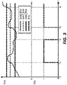
Figure 3 shows a graph representing the evolution of E1p and S1p. -
Figure 4 shows a block diagram representing the E1p calculation process (energy 1p). -
Figure 5 shows a graph representing the evolution of the pitch control parameters in accordance with the wind, where the aerodynamic stall zone and normal operation zone can be observed on either side of the dashed line. -
Figure 6 shows a graph representing the evolution of the pitch control parameters in accordance with the wind, where the central curve represents the evolution of the threshold values. - In light of the figures, following is a preferred embodiment of the object of this invention.
- The present idea enables the wind turbine to continue functioning in situations in which the rotor has an aerodynamic or mass anomaly by using the method described herein and illustrated in
figure 2c : - A first phase involving the detection and diagnosis of the variation of the physical properties of the blades with respect to the design properties (discriminating whether this variation is balanced between the blades, normally three blades).
- A second phase, based on the variation previously determined, in which the wind turbine control parameters are modified.
- A type of variation in the physical properties of the blades currently known is the aerodynamic and/or mass variation associated with the deposition of ice or dirt on the blades, the effect of which, among others, is the modification of the curves Cp (λ, β) that define the power coefficients of the blades for each working point (λ is defined as the coefficient between the linear speed of the tip of the blade and wind speed and β corresponds to the blade pitch angle).
-
Figure 1 shows the typical power curves of a wind turbine for different blade pitch angles, which determine the power captured by the wind turbine rotor depending on rotation speed and the area swept, as indicated in the formula below:
- Said
figure 1 also shows a static curve that follows the blade pitch angle commanded by the wind turbine controller during normal operation according to the state of the art: in general, the position of 0° is selected to function near maximum Cp in the variable wind turbine speed zone; once nominal power is reached, the controller increases the blade pitch angle setpoint in order to control the rotation speed of the rotor at approximately the nominal rotation speed (ωref). The curves Cp (λ, β) are very sensitive to changes in profile shape, which occur when there is ice or dirt on the blades. Ice can be deposited on the blades in a balanced manner, i.e. in the same manner and quantity on all the blades when the wind turbine is rotating, or in an unbalanced manner, i.e. in a different manner and quantity between at least two wind turbine blades, which usually occurs when the wind turbine is stopped or when ice falls off one of the blades. - An unbalanced (or non-balanced) modification of the shape or mass of the blade profiles causes the appearance of harmonic 1p values (at rotor rotation frequency) in certain data representative of wind turbine status, such as wind turbine rotor rotation speed, torque and loads which are greater than the values obtained during operation without rotor imbalance. This can be harmful to the wind turbine as it worsens the fatigue performance thereof, due to which once a certain level of energy in the harmonic 1p is exceeded, i.e. once an imbalance in the blades is detected, a controller according to the state of the art will stop the wind turbine, causing non-availability thereof and a decrease in the energy produced.
- Alternatively to the detection of an
energy 1p value greater than a threshold value, an optical inspection could be carried out by means of sensors that capture the shape of the blade profiles for detecting rotor imbalance. - In order to discriminate the existence of an unbalanced variation in the geometry of the wind turbine blade profiles and limit the non-availability of the wind turbine, according to the method proposed in the present invention, the following steps are carried out, as shown in
figures 2c ,3 and4 : - At least one parameter representative of wind turbine operating status, which can be, for example, turbine rotation speed (ωmed) is determined by means of a series of sensors, although it may also be a parameter relating to torque, wind turbine loads or any electrical variable.
- A first signal indicative of an unbalanced variation in the aerodynamic profile of the blades is calculated, for example, a signal indicative of the energy of the harmonic 1p obtained from said parameter relating to wind turbine operation.
- The sign indicative of the energy of the harmonic 1p is compared to a first threshold value (Lim1_1E1p), which in a preferred embodiment will be lower than the threshold value for which the wind turbine was designed.
- If the sign indicative of the energy of the harmonic 1p is greater than the first threshold value (Lim1_E1p), the torque controller and/or pitch controller is modified, switching the signal from the corresponding controller for passage thereof through a filter at a frequency of 1p, i.e. activating a first and/or second filter (F2(1p), F1(1p)) at a frequency of 1p, which prevents the torque and pitch controllers from working at that frequency (S1p=1). This prevents the control actions from amplifying the level of vibrations and loads at that frequency (indicated by the
energy level 1p) and the sign indicative ofenergy 1p falls below critical values. - Additionally, according to the invention, the first signal indicative of the harmonic 1p (E1p) is compared to a second threshold value (Lim2_E1p) greater than the first threshold value (Lim1_E1p), above which the wind generator is disconnected.
- In order to prevent the pitch control loop such as that shown in
figure 2a or the torque control loop shown infigure 2b from switching constantly between the branch wherein a filter is applied and the branch wherein a filter is not applied, i.e. to prevent the first filter F2(1p) from becoming constantly activated and deactivated, the signal indicative of the harmonic 1p (E1p) is compared to a third threshold value (Lim3_E1p) lower than the first threshold value (Lim1_E1p) and when the signal indicative of the harmonic 1p (E1p) returns to values lower than the third threshold value, the signal from the controller switches again to prevent it from passing through the filter at a frequency of 1p (S1p=0). - If these filters (F1(1p) and F2(1P)) were to become activated during normal operation, the dynamic characteristics of the controllers would be modified and would no longer be optimal for wind turbine control. However, as they only become activated when an unbalanced anomaly is detected in the rotor (when the
energy 1p level is greater than the first threshold value), the controllers do not lose their effectiveness during normal operation and are not activated, amplifying the load level at a frequency of 1p. - The balanced modification of the aerodynamics of the blade profiles and, therefore, of the curves Cp (λ, β), can cause the blade to enter a stall condition (delimited by the curve defined by the dashed line that crosses points (β1, β2, β3) of
figure 5 and the central curve offigure 6 ), wherein an increase in wind speed implies a reduction in captured power. - In this situation, a wind turbine control according to the state of the art would tend to move towards smaller angles of attack in order to increase power to the nominal zone, which increases the loads in the blade In this situation, the blades enter an aerodynamic zone not envisaged in a control according to the state of the art and are more exposed to the wind, in such a manner that in the event of ice falling off or gusts of wind, it can give rise to high loads that could damage wind turbine components such as the blades or hub.
- Therefore, the control method proposed comprises the step of comparing a second signal to a fourth threshold value, where said second signal is a current blade pitch signal and said fourth threshold value (β_threshold) is a blade pitch value greater than that of blade pitch entering a stall condition (β_lim_loss), to determine balanced variations in the aerodynamic profile of at least one wind turbine blade.
- To this end, in a preferred embodiment the following steps are carried out:
- A signal indicative of wind speed is taken (which will normally be a filtered signal of the measurement made by the anemometer).
- The blade pitch angle measurement is compared to a certain blade pitch threshold (β_threshold) which corresponds to a blade pitch value greater than or equal to that of a blade entering a stall condition at the wind speed indicated by the signal indicative of wind (alternatively, a comparison can be made between the power generated and that corresponding to that level of wind). Preferably, the threshold pitch value is greater than that on entering a stall condition (β_lim_loss) and lower than the value during normal operation (β_normal).
- If the blade pitch measurement is lower than the threshold value, the pitch controller is modified, establishing a new minimum pitch value β_min_mod. Preferably, the modified minimum pitch value β_min_mod is greater than the threshold stall pitch value β_lim_loss (in the state of the art, the minimum threshold pitch βmin_ET is predetermined and independent of wind speed; generally equal to zero or the angle of maximum production).
- The technical effect of this characteristic of the control method proposed when the anomaly existing in the blades is balanced is to prevent the pitch angle from being very small (approximately equal to zero or the angle of maximum production) as a consequence of the modification of the aerodynamic characteristics of the blades that cause the profiles to enter a stall condition. When this occurs, a controller according to the state of the art will tend to decrease the blade pitch angle to attempt to correct the power loss associated with aerodynamic loss, even if wind speed increases. This leads to an increase in wind turbine loads. To avoid this, a controller according to the state of the art, upon detecting the anomaly in the blades, disconnects the wind turbine, causing a reduction in the availability of the machine and in the energy produced.
Claims (11)
- A method for controlling a wind turbine that comprises a series of blades, said method comprising the following steps:- determining, by means of a series of sensors, at least one parameter representative of the wind turbine operating status;- calculating a first signal sensitive to unbalanced variations in the aerodynamic profile between the blades based on the at least one parameter representative of the wind turbine operating status, the first signal being a result of a calculation of a harmonic 1p at the rotation frequency of a rotor of the wind turbine based on the at least one parameter representative of the wind turbine operating status;- comparing said first signal to a first threshold value;- determining the existence of an unbalanced variation in the aerodynamic profile between the blades if the first signal exceeds the first threshold value;- modifying at least one torque control loop if the existence of an unbalanced variation in the aerodynamic profile of the blades is determined in the former step; and- comparing the first signal to a second threshold value, where said second threshold value is a value as of which the wind turbine is disconnected, said second threshold value being greater than the first threshold value.
- Method, according to claim 1, characterised in that the parameter representative of the wind turbine operating status is selected from: speed, torque, wind turbine loads and electrical variables.
- Method, according to either claim 1 or 2, characterised in that modifying at least one torque control loop comprises activating a first filter at a frequency of 1p in the torque control loop.
- Method, according to claim 3, further comprising modifying a blade pitch control loop by including a second filter at a frequency of 1p in the aforementioned blade pitch control loop.
- Method, according to any of claims 1 to 4, further comprising comparing the first signal to a third threshold value, where said third threshold value is a value smaller than the first threshold value, and deactivating the first filter at a frequency of 1p in the torque control loop if the first signal is less than the third threshold value and the first filter is activated.
- Method, according to claim 1, further comprising the step of comparing a second signal with a fourth threshold value, where said second signal is a current blade pitch signal and said fourth threshold value is a blade pitch value greater than that of a blade entering a stall condition.
- Method, according to claim 6, further comprising modifying the blade control pitch loop when the value of the second signal is lower than the value of the fourth threshold value.
- Method, according to claim 7, characterised in that modifying the blade pitch control loop comprises temporarily modifying the minimum blade pitch angle threshold and equating it to a value greater than or equal to that of the fourth threshold value.
- Method, according to claim 8, characterised in that the fourth threshold value is constant and predetermined.
- Method, according to claim 8, characterised in that the fourth threshold value is dependent on wind speed.
- Method, according to any one of claims 6 to 10, characterised in that it additionally comprises comparing the second signal to a fifth threshold value, where said fifth threshold value is a value as of which the wind generator is disconnected, said fifth threshold value being greater than the fourth threshold value.
Applications Claiming Priority (1)
| Application Number | Priority Date | Filing Date | Title |
|---|---|---|---|
| ES201231088A ES2442452B1 (en) | 2012-07-11 | 2012-07-11 | METHOD OF AIRCRAFT CONTROL |
Publications (3)
| Publication Number | Publication Date |
|---|---|
| EP2685092A2 EP2685092A2 (en) | 2014-01-15 |
| EP2685092A3 EP2685092A3 (en) | 2017-07-19 |
| EP2685092B1 true EP2685092B1 (en) | 2022-08-31 |
Family
ID=48917335
Family Applications (1)
| Application Number | Title | Priority Date | Filing Date |
|---|---|---|---|
| EP13176124.9A Active EP2685092B1 (en) | 2012-07-11 | 2013-07-11 | Wind turbine control method based on blade profile change |
Country Status (4)
| Country | Link |
|---|---|
| US (1) | US9523349B2 (en) |
| EP (1) | EP2685092B1 (en) |
| DK (1) | DK2685092T3 (en) |
| ES (2) | ES2442452B1 (en) |
Families Citing this family (4)
| Publication number | Priority date | Publication date | Assignee | Title |
|---|---|---|---|---|
| CN105222742A (en) * | 2014-05-26 | 2016-01-06 | 通用电气公司 | Slurry is apart from fault detection system and method |
| CN104088753B (en) * | 2014-06-24 | 2016-09-28 | 许继集团有限公司 | A kind of Large-scale Wind Turbines increases the spike adjustment control method of minimum headroom |
| CN117167205A (en) * | 2022-05-27 | 2023-12-05 | 金风科技股份有限公司 | Abnormal detection method, controller and wind turbine of wind turbine pitch system |
| EP4442989A1 (en) | 2023-04-04 | 2024-10-09 | Nordex Energy SE & Co. KG | Method for operating a wind turbine and wind turbine |
Family Cites Families (14)
| Publication number | Priority date | Publication date | Assignee | Title |
|---|---|---|---|---|
| US5155375A (en) * | 1991-09-19 | 1992-10-13 | U.S. Windpower, Inc. | Speed control system for a variable speed wind turbine |
| DE10323785B4 (en) | 2003-05-23 | 2009-09-10 | Wobben, Aloys, Dipl.-Ing. | Method for detecting an ice accumulation on rotor blades |
| US7086834B2 (en) * | 2004-06-10 | 2006-08-08 | General Electric Company | Methods and apparatus for rotor blade ice detection |
| MX2008011751A (en) * | 2006-03-16 | 2008-11-12 | Vestas Wind Sys As | A method and control system for reducing the fatigue loads in the components of a wind turbine subjected to asymmetrical loading of the rotor plane. |
| EP2079927A1 (en) * | 2006-10-02 | 2009-07-22 | Clipper Windpower Technology, Inc. | Wind turbine with blade pitch control to compensate for wind shear and wind misalignment |
| CN101720387B (en) * | 2007-03-30 | 2014-01-08 | 维斯塔斯风力系统有限公司 | Wind turbine with pitch control arranged to reduce life shortening loads on components thereof |
| US8277185B2 (en) * | 2007-12-28 | 2012-10-02 | General Electric Company | Wind turbine, wind turbine controller and method for controlling a wind turbine |
| CN102066747A (en) * | 2008-06-23 | 2011-05-18 | 丹麦技术大学 | A wind turbine blade with angled girders |
| US8096761B2 (en) * | 2008-10-16 | 2012-01-17 | General Electric Company | Blade pitch management method and system |
| CA2716497C (en) * | 2009-06-26 | 2013-11-12 | Mitsubishi Heavy Industries, Ltd. | Wind turbine generator and method of controlling the same |
| DE102010002203B4 (en) * | 2010-02-22 | 2014-05-15 | Senvion Se | Method for operating a wind energy plant |
| US8405251B2 (en) * | 2010-04-20 | 2013-03-26 | General Electric Company | Method and apparatus for reduction of harmonics in a power supply |
| US8292579B2 (en) * | 2011-11-03 | 2012-10-23 | General Electric Company | Method and system for deicing wind turbine rotor blades with induced torque |
| US20120133134A1 (en) * | 2011-11-15 | 2012-05-31 | General Electric Company | Method and apparatus for damping vibrations in a wind energy system |
-
2012
- 2012-07-11 ES ES201231088A patent/ES2442452B1/en active Active
-
2013
- 2013-07-10 US US13/938,343 patent/US9523349B2/en active Active
- 2013-07-11 ES ES13176124T patent/ES2930425T3/en active Active
- 2013-07-11 DK DK13176124.9T patent/DK2685092T3/en active
- 2013-07-11 EP EP13176124.9A patent/EP2685092B1/en active Active
Also Published As
| Publication number | Publication date |
|---|---|
| EP2685092A3 (en) | 2017-07-19 |
| US9523349B2 (en) | 2016-12-20 |
| DK2685092T3 (en) | 2022-11-21 |
| EP2685092A2 (en) | 2014-01-15 |
| ES2442452R1 (en) | 2014-03-06 |
| US20140028024A1 (en) | 2014-01-30 |
| ES2930425T3 (en) | 2022-12-12 |
| ES2442452B1 (en) | 2014-12-22 |
| ES2442452A2 (en) | 2014-02-11 |
Similar Documents
| Publication | Publication Date | Title |
|---|---|---|
| US8167556B2 (en) | Method and apparatus for damping tower oscillation in a wind turbine | |
| US8803351B2 (en) | Control method for a wind turbine | |
| US10107261B2 (en) | System and method for reducing oscillation loads of wind turbine | |
| US10982653B2 (en) | Adaptive control of a wind turbine by detecting a change in performance | |
| DK2886854T3 (en) | Method for controlling wind turbine | |
| CN105793561B (en) | Basic grid regulation for wind power plants | |
| EP2878809B1 (en) | Methods of operating a wind turbine, wind turbines and wind parks | |
| US9709033B2 (en) | Method for controlling a wind turbine during shutdown | |
| CN111512043B (en) | Method and system for controlling wind turbines to manage edge blade vibration | |
| US9523349B2 (en) | Wind turbine control method | |
| US20170328342A1 (en) | Power ramp rate limiter for wind turbines | |
| US20230176533A1 (en) | Model-based predictive control method for structural load reduction in wind turbines | |
| EP2995810A1 (en) | Control method for a wind turbine | |
| JP2018538476A (en) | Control method for wind turbine generator | |
| CA2889104C (en) | Method for operating a wind energy installation, and wind energy installation | |
| US20240175423A1 (en) | Method for controlling a wind power installation | |
| CN203515959U (en) | Three-order frequency vibration abatement system for wind turbine blades in wind turbine impeller rotation plane | |
| EP3881427A1 (en) | Method for stabilising a rotor of a wind turbine | |
| DK202170577A1 (en) | Controller for a wind turbine | |
| CN119102975B (en) | A Resonance Ride-Through Control Method and System Based on Wind Turbine Model |
Legal Events
| Date | Code | Title | Description |
|---|---|---|---|
| PUAI | Public reference made under article 153(3) epc to a published international application that has entered the european phase |
Free format text: ORIGINAL CODE: 0009012 |
|
| AK | Designated contracting states |
Kind code of ref document: A2 Designated state(s): AL AT BE BG CH CY CZ DE DK EE ES FI FR GB GR HR HU IE IS IT LI LT LU LV MC MK MT NL NO PL PT RO RS SE SI SK SM TR |
|
| AX | Request for extension of the european patent |
Extension state: BA ME |
|
| PUAL | Search report despatched |
Free format text: ORIGINAL CODE: 0009013 |
|
| AK | Designated contracting states |
Kind code of ref document: A3 Designated state(s): AL AT BE BG CH CY CZ DE DK EE ES FI FR GB GR HR HU IE IS IT LI LT LU LV MC MK MT NL NO PL PT RO RS SE SI SK SM TR |
|
| AX | Request for extension of the european patent |
Extension state: BA ME |
|
| RIC1 | Information provided on ipc code assigned before grant |
Ipc: F03D 11/00 00000000ALI20170609BHEP Ipc: F03D 1/06 20060101ALI20170609BHEP Ipc: F03D 7/00 20060101AFI20170609BHEP Ipc: F03D 7/02 20060101ALI20170609BHEP |
|
| STAA | Information on the status of an ep patent application or granted ep patent |
Free format text: STATUS: REQUEST FOR EXAMINATION WAS MADE |
|
| RBV | Designated contracting states (corrected) |
Designated state(s): AL AT BE BG CH CY CZ DE DK EE ES FI FR GB GR HR HU IE IS IT LI LT LU LV MC MK MT NL NO PL PT RO RS SE SI SK SM TR |
|
| 17P | Request for examination filed |
Effective date: 20180122 |
|
| STAA | Information on the status of an ep patent application or granted ep patent |
Free format text: STATUS: EXAMINATION IS IN PROGRESS |
|
| 17Q | First examination report despatched |
Effective date: 20200615 |
|
| RAP1 | Party data changed (applicant data changed or rights of an application transferred) |
Owner name: NORDEX ENERGY SPAIN, S.A. |
|
| RIC1 | Information provided on ipc code assigned before grant |
Ipc: F03D 7/02 20060101ALI20211208BHEP Ipc: F03D 1/06 20060101ALI20211208BHEP Ipc: F03D 7/00 20060101AFI20211208BHEP |
|
| GRAP | Despatch of communication of intention to grant a patent |
Free format text: ORIGINAL CODE: EPIDOSNIGR1 |
|
| STAA | Information on the status of an ep patent application or granted ep patent |
Free format text: STATUS: GRANT OF PATENT IS INTENDED |
|
| INTG | Intention to grant announced |
Effective date: 20220207 |
|
| GRAS | Grant fee paid |
Free format text: ORIGINAL CODE: EPIDOSNIGR3 |
|
| GRAA | (expected) grant |
Free format text: ORIGINAL CODE: 0009210 |
|
| STAA | Information on the status of an ep patent application or granted ep patent |
Free format text: STATUS: THE PATENT HAS BEEN GRANTED |
|
| AK | Designated contracting states |
Kind code of ref document: B1 Designated state(s): AL AT BE BG CH CY CZ DE DK EE ES FI FR GB GR HR HU IE IS IT LI LT LU LV MC MK MT NL NO PL PT RO RS SE SI SK SM TR |
|
| REG | Reference to a national code |
Ref country code: CH Ref legal event code: EP Ref country code: GB Ref legal event code: FG4D |
|
| REG | Reference to a national code |
Ref country code: AT Ref legal event code: REF Ref document number: 1515460 Country of ref document: AT Kind code of ref document: T Effective date: 20220915 Ref country code: DE Ref legal event code: R096 Ref document number: 602013082416 Country of ref document: DE |
|
| REG | Reference to a national code |
Ref country code: IE Ref legal event code: FG4D |
|
| REG | Reference to a national code |
Ref country code: DK Ref legal event code: T3 Effective date: 20221116 |
|
| REG | Reference to a national code |
Ref country code: SE Ref legal event code: TRGR |
|
| REG | Reference to a national code |
Ref country code: ES Ref legal event code: FG2A Ref document number: 2930425 Country of ref document: ES Kind code of ref document: T3 Effective date: 20221212 |
|
| REG | Reference to a national code |
Ref country code: LT Ref legal event code: MG9D |
|
| REG | Reference to a national code |
Ref country code: NL Ref legal event code: MP Effective date: 20220831 |
|
| REG | Reference to a national code |
Ref country code: NO Ref legal event code: T2 Effective date: 20220831 |
|
| PG25 | Lapsed in a contracting state [announced via postgrant information from national office to epo] |
Ref country code: RS Free format text: LAPSE BECAUSE OF FAILURE TO SUBMIT A TRANSLATION OF THE DESCRIPTION OR TO PAY THE FEE WITHIN THE PRESCRIBED TIME-LIMIT Effective date: 20220831 Ref country code: LV Free format text: LAPSE BECAUSE OF FAILURE TO SUBMIT A TRANSLATION OF THE DESCRIPTION OR TO PAY THE FEE WITHIN THE PRESCRIBED TIME-LIMIT Effective date: 20220831 Ref country code: LT Free format text: LAPSE BECAUSE OF FAILURE TO SUBMIT A TRANSLATION OF THE DESCRIPTION OR TO PAY THE FEE WITHIN THE PRESCRIBED TIME-LIMIT Effective date: 20220831 |
|
| REG | Reference to a national code |
Ref country code: AT Ref legal event code: MK05 Ref document number: 1515460 Country of ref document: AT Kind code of ref document: T Effective date: 20220831 |
|
| PG25 | Lapsed in a contracting state [announced via postgrant information from national office to epo] |
Ref country code: PL Free format text: LAPSE BECAUSE OF FAILURE TO SUBMIT A TRANSLATION OF THE DESCRIPTION OR TO PAY THE FEE WITHIN THE PRESCRIBED TIME-LIMIT Effective date: 20220831 Ref country code: IS Free format text: LAPSE BECAUSE OF FAILURE TO SUBMIT A TRANSLATION OF THE DESCRIPTION OR TO PAY THE FEE WITHIN THE PRESCRIBED TIME-LIMIT Effective date: 20221231 Ref country code: HR Free format text: LAPSE BECAUSE OF FAILURE TO SUBMIT A TRANSLATION OF THE DESCRIPTION OR TO PAY THE FEE WITHIN THE PRESCRIBED TIME-LIMIT Effective date: 20220831 Ref country code: GR Free format text: LAPSE BECAUSE OF FAILURE TO SUBMIT A TRANSLATION OF THE DESCRIPTION OR TO PAY THE FEE WITHIN THE PRESCRIBED TIME-LIMIT Effective date: 20221201 |
|
| PG25 | Lapsed in a contracting state [announced via postgrant information from national office to epo] |
Ref country code: SM Free format text: LAPSE BECAUSE OF FAILURE TO SUBMIT A TRANSLATION OF THE DESCRIPTION OR TO PAY THE FEE WITHIN THE PRESCRIBED TIME-LIMIT Effective date: 20220831 Ref country code: RO Free format text: LAPSE BECAUSE OF FAILURE TO SUBMIT A TRANSLATION OF THE DESCRIPTION OR TO PAY THE FEE WITHIN THE PRESCRIBED TIME-LIMIT Effective date: 20220831 Ref country code: PT Free format text: LAPSE BECAUSE OF FAILURE TO SUBMIT A TRANSLATION OF THE DESCRIPTION OR TO PAY THE FEE WITHIN THE PRESCRIBED TIME-LIMIT Effective date: 20230102 Ref country code: CZ Free format text: LAPSE BECAUSE OF FAILURE TO SUBMIT A TRANSLATION OF THE DESCRIPTION OR TO PAY THE FEE WITHIN THE PRESCRIBED TIME-LIMIT Effective date: 20220831 Ref country code: AT Free format text: LAPSE BECAUSE OF FAILURE TO SUBMIT A TRANSLATION OF THE DESCRIPTION OR TO PAY THE FEE WITHIN THE PRESCRIBED TIME-LIMIT Effective date: 20220831 |
|
| PG25 | Lapsed in a contracting state [announced via postgrant information from national office to epo] |
Ref country code: SK Free format text: LAPSE BECAUSE OF FAILURE TO SUBMIT A TRANSLATION OF THE DESCRIPTION OR TO PAY THE FEE WITHIN THE PRESCRIBED TIME-LIMIT Effective date: 20220831 Ref country code: EE Free format text: LAPSE BECAUSE OF FAILURE TO SUBMIT A TRANSLATION OF THE DESCRIPTION OR TO PAY THE FEE WITHIN THE PRESCRIBED TIME-LIMIT Effective date: 20220831 |
|
| REG | Reference to a national code |
Ref country code: DE Ref legal event code: R097 Ref document number: 602013082416 Country of ref document: DE |
|
| PG25 | Lapsed in a contracting state [announced via postgrant information from national office to epo] |
Ref country code: NL Free format text: LAPSE BECAUSE OF FAILURE TO SUBMIT A TRANSLATION OF THE DESCRIPTION OR TO PAY THE FEE WITHIN THE PRESCRIBED TIME-LIMIT Effective date: 20220831 Ref country code: AL Free format text: LAPSE BECAUSE OF FAILURE TO SUBMIT A TRANSLATION OF THE DESCRIPTION OR TO PAY THE FEE WITHIN THE PRESCRIBED TIME-LIMIT Effective date: 20220831 |
|
| PLBE | No opposition filed within time limit |
Free format text: ORIGINAL CODE: 0009261 |
|
| STAA | Information on the status of an ep patent application or granted ep patent |
Free format text: STATUS: NO OPPOSITION FILED WITHIN TIME LIMIT |
|
| P01 | Opt-out of the competence of the unified patent court (upc) registered |
Effective date: 20230529 |
|
| 26N | No opposition filed |
Effective date: 20230601 |
|
| PG25 | Lapsed in a contracting state [announced via postgrant information from national office to epo] |
Ref country code: SI Free format text: LAPSE BECAUSE OF FAILURE TO SUBMIT A TRANSLATION OF THE DESCRIPTION OR TO PAY THE FEE WITHIN THE PRESCRIBED TIME-LIMIT Effective date: 20220831 |
|
| PG25 | Lapsed in a contracting state [announced via postgrant information from national office to epo] |
Ref country code: MC Free format text: LAPSE BECAUSE OF FAILURE TO SUBMIT A TRANSLATION OF THE DESCRIPTION OR TO PAY THE FEE WITHIN THE PRESCRIBED TIME-LIMIT Effective date: 20220831 |
|
| PG25 | Lapsed in a contracting state [announced via postgrant information from national office to epo] |
Ref country code: MC Free format text: LAPSE BECAUSE OF FAILURE TO SUBMIT A TRANSLATION OF THE DESCRIPTION OR TO PAY THE FEE WITHIN THE PRESCRIBED TIME-LIMIT Effective date: 20220831 |
|
| REG | Reference to a national code |
Ref country code: CH Ref legal event code: PL |
|
| REG | Reference to a national code |
Ref country code: BE Ref legal event code: MM Effective date: 20230731 |
|
| PG25 | Lapsed in a contracting state [announced via postgrant information from national office to epo] |
Ref country code: LU Free format text: LAPSE BECAUSE OF NON-PAYMENT OF DUE FEES Effective date: 20230711 |
|
| GBPC | Gb: european patent ceased through non-payment of renewal fee |
Effective date: 20230711 |
|
| PG25 | Lapsed in a contracting state [announced via postgrant information from national office to epo] |
Ref country code: LU Free format text: LAPSE BECAUSE OF NON-PAYMENT OF DUE FEES Effective date: 20230711 |
|
| REG | Reference to a national code |
Ref country code: IE Ref legal event code: MM4A |
|
| PG25 | Lapsed in a contracting state [announced via postgrant information from national office to epo] |
Ref country code: CH Free format text: LAPSE BECAUSE OF NON-PAYMENT OF DUE FEES Effective date: 20230731 Ref country code: GB Free format text: LAPSE BECAUSE OF NON-PAYMENT OF DUE FEES Effective date: 20230711 |
|
| PG25 | Lapsed in a contracting state [announced via postgrant information from national office to epo] |
Ref country code: IT Free format text: LAPSE BECAUSE OF FAILURE TO SUBMIT A TRANSLATION OF THE DESCRIPTION OR TO PAY THE FEE WITHIN THE PRESCRIBED TIME-LIMIT Effective date: 20220831 Ref country code: FR Free format text: LAPSE BECAUSE OF NON-PAYMENT OF DUE FEES Effective date: 20230731 Ref country code: BE Free format text: LAPSE BECAUSE OF NON-PAYMENT OF DUE FEES Effective date: 20230731 |
|
| PG25 | Lapsed in a contracting state [announced via postgrant information from national office to epo] |
Ref country code: IE Free format text: LAPSE BECAUSE OF NON-PAYMENT OF DUE FEES Effective date: 20230711 |
|
| PG25 | Lapsed in a contracting state [announced via postgrant information from national office to epo] |
Ref country code: IE Free format text: LAPSE BECAUSE OF NON-PAYMENT OF DUE FEES Effective date: 20230711 |
|
| PG25 | Lapsed in a contracting state [announced via postgrant information from national office to epo] |
Ref country code: BG Free format text: LAPSE BECAUSE OF FAILURE TO SUBMIT A TRANSLATION OF THE DESCRIPTION OR TO PAY THE FEE WITHIN THE PRESCRIBED TIME-LIMIT Effective date: 20220831 |
|
| PG25 | Lapsed in a contracting state [announced via postgrant information from national office to epo] |
Ref country code: BG Free format text: LAPSE BECAUSE OF FAILURE TO SUBMIT A TRANSLATION OF THE DESCRIPTION OR TO PAY THE FEE WITHIN THE PRESCRIBED TIME-LIMIT Effective date: 20220831 |
|
| PG25 | Lapsed in a contracting state [announced via postgrant information from national office to epo] |
Ref country code: CY Free format text: LAPSE BECAUSE OF FAILURE TO SUBMIT A TRANSLATION OF THE DESCRIPTION OR TO PAY THE FEE WITHIN THE PRESCRIBED TIME-LIMIT; INVALID AB INITIO Effective date: 20130711 |
|
| PG25 | Lapsed in a contracting state [announced via postgrant information from national office to epo] |
Ref country code: HU Free format text: LAPSE BECAUSE OF FAILURE TO SUBMIT A TRANSLATION OF THE DESCRIPTION OR TO PAY THE FEE WITHIN THE PRESCRIBED TIME-LIMIT; INVALID AB INITIO Effective date: 20130711 |
|
| PGFP | Annual fee paid to national office [announced via postgrant information from national office to epo] |
Ref country code: ES Payment date: 20250819 Year of fee payment: 13 Ref country code: FI Payment date: 20250722 Year of fee payment: 13 |
|
| PGFP | Annual fee paid to national office [announced via postgrant information from national office to epo] |
Ref country code: DK Payment date: 20250723 Year of fee payment: 13 Ref country code: DE Payment date: 20250722 Year of fee payment: 13 |
|
| PGFP | Annual fee paid to national office [announced via postgrant information from national office to epo] |
Ref country code: NO Payment date: 20250722 Year of fee payment: 13 |
|
| PGFP | Annual fee paid to national office [announced via postgrant information from national office to epo] |
Ref country code: SE Payment date: 20250723 Year of fee payment: 13 |
|
| PG25 | Lapsed in a contracting state [announced via postgrant information from national office to epo] |
Ref country code: TR Free format text: LAPSE BECAUSE OF FAILURE TO SUBMIT A TRANSLATION OF THE DESCRIPTION OR TO PAY THE FEE WITHIN THE PRESCRIBED TIME-LIMIT Effective date: 20220831 |