EP2684547A1 - Fasteners - Google Patents
Fasteners Download PDFInfo
- Publication number
- EP2684547A1 EP2684547A1 EP12176222.3A EP12176222A EP2684547A1 EP 2684547 A1 EP2684547 A1 EP 2684547A1 EP 12176222 A EP12176222 A EP 12176222A EP 2684547 A1 EP2684547 A1 EP 2684547A1
- Authority
- EP
- European Patent Office
- Prior art keywords
- fasteners
- fastener
- web
- recess
- arm
- Prior art date
- Legal status (The legal status is an assumption and is not a legal conclusion. Google has not performed a legal analysis and makes no representation as to the accuracy of the status listed.)
- Granted
Links
- 230000002745 absorbent Effects 0.000 claims description 28
- 239000002250 absorbent Substances 0.000 claims description 28
- 239000000853 adhesive Substances 0.000 claims description 7
- 230000001070 adhesive effect Effects 0.000 claims description 7
- 238000000034 method Methods 0.000 claims description 7
- 229920005992 thermoplastic resin Polymers 0.000 claims description 7
- 238000004519 manufacturing process Methods 0.000 claims description 3
- 239000002699 waste material Substances 0.000 description 5
- 239000000463 material Substances 0.000 description 4
- 206010021639 Incontinence Diseases 0.000 description 3
- 238000005520 cutting process Methods 0.000 description 3
- 239000002390 adhesive tape Substances 0.000 description 2
- 230000001788 irregular Effects 0.000 description 2
- 239000007788 liquid Substances 0.000 description 2
- 230000014759 maintenance of location Effects 0.000 description 2
- 239000011248 coating agent Substances 0.000 description 1
- 238000000576 coating method Methods 0.000 description 1
- 238000010276 construction Methods 0.000 description 1
- 238000009826 distribution Methods 0.000 description 1
- 238000004806 packaging method and process Methods 0.000 description 1
- 239000002243 precursor Substances 0.000 description 1
- 229940081330 tena Drugs 0.000 description 1
- 238000009966 trimming Methods 0.000 description 1
- 230000003313 weakening effect Effects 0.000 description 1
Images


Classifications
-
- A—HUMAN NECESSITIES
- A61—MEDICAL OR VETERINARY SCIENCE; HYGIENE
- A61F—FILTERS IMPLANTABLE INTO BLOOD VESSELS; PROSTHESES; DEVICES PROVIDING PATENCY TO, OR PREVENTING COLLAPSING OF, TUBULAR STRUCTURES OF THE BODY, e.g. STENTS; ORTHOPAEDIC, NURSING OR CONTRACEPTIVE DEVICES; FOMENTATION; TREATMENT OR PROTECTION OF EYES OR EARS; BANDAGES, DRESSINGS OR ABSORBENT PADS; FIRST-AID KITS
- A61F13/00—Bandages or dressings; Absorbent pads
- A61F13/15—Absorbent pads, e.g. sanitary towels, swabs or tampons for external or internal application to the body; Supporting or fastening means therefor; Tampon applicators
- A61F13/56—Supporting or fastening means
- A61F13/62—Mechanical fastening means ; Fabric strip fastener elements, e.g. hook and loop
- A61F13/622—Fabric strip fastener elements, e.g. hook and loop
-
- A—HUMAN NECESSITIES
- A44—HABERDASHERY; JEWELLERY
- A44B—BUTTONS, PINS, BUCKLES, SLIDE FASTENERS, OR THE LIKE
- A44B18/00—Fasteners of the touch-and-close type; Making such fasteners
- A44B18/0069—Details
- A44B18/0073—Attaching means
-
- A—HUMAN NECESSITIES
- A61—MEDICAL OR VETERINARY SCIENCE; HYGIENE
- A61F—FILTERS IMPLANTABLE INTO BLOOD VESSELS; PROSTHESES; DEVICES PROVIDING PATENCY TO, OR PREVENTING COLLAPSING OF, TUBULAR STRUCTURES OF THE BODY, e.g. STENTS; ORTHOPAEDIC, NURSING OR CONTRACEPTIVE DEVICES; FOMENTATION; TREATMENT OR PROTECTION OF EYES OR EARS; BANDAGES, DRESSINGS OR ABSORBENT PADS; FIRST-AID KITS
- A61F13/00—Bandages or dressings; Absorbent pads
- A61F13/15—Absorbent pads, e.g. sanitary towels, swabs or tampons for external or internal application to the body; Supporting or fastening means therefor; Tampon applicators
- A61F13/15577—Apparatus or processes for manufacturing
- A61F13/15756—Applying tabs, strips, tapes, loops; Knotting the ends of pads
-
- A—HUMAN NECESSITIES
- A61—MEDICAL OR VETERINARY SCIENCE; HYGIENE
- A61F—FILTERS IMPLANTABLE INTO BLOOD VESSELS; PROSTHESES; DEVICES PROVIDING PATENCY TO, OR PREVENTING COLLAPSING OF, TUBULAR STRUCTURES OF THE BODY, e.g. STENTS; ORTHOPAEDIC, NURSING OR CONTRACEPTIVE DEVICES; FOMENTATION; TREATMENT OR PROTECTION OF EYES OR EARS; BANDAGES, DRESSINGS OR ABSORBENT PADS; FIRST-AID KITS
- A61F13/00—Bandages or dressings; Absorbent pads
- A61F13/15—Absorbent pads, e.g. sanitary towels, swabs or tampons for external or internal application to the body; Supporting or fastening means therefor; Tampon applicators
- A61F13/56—Supporting or fastening means
- A61F13/5622—Supporting or fastening means specially adapted for diapers or the like
-
- A—HUMAN NECESSITIES
- A61—MEDICAL OR VETERINARY SCIENCE; HYGIENE
- A61F—FILTERS IMPLANTABLE INTO BLOOD VESSELS; PROSTHESES; DEVICES PROVIDING PATENCY TO, OR PREVENTING COLLAPSING OF, TUBULAR STRUCTURES OF THE BODY, e.g. STENTS; ORTHOPAEDIC, NURSING OR CONTRACEPTIVE DEVICES; FOMENTATION; TREATMENT OR PROTECTION OF EYES OR EARS; BANDAGES, DRESSINGS OR ABSORBENT PADS; FIRST-AID KITS
- A61F13/00—Bandages or dressings; Absorbent pads
- A61F13/15—Absorbent pads, e.g. sanitary towels, swabs or tampons for external or internal application to the body; Supporting or fastening means therefor; Tampon applicators
- A61F13/56—Supporting or fastening means
- A61F13/62—Mechanical fastening means ; Fabric strip fastener elements, e.g. hook and loop
-
- Y—GENERAL TAGGING OF NEW TECHNOLOGICAL DEVELOPMENTS; GENERAL TAGGING OF CROSS-SECTIONAL TECHNOLOGIES SPANNING OVER SEVERAL SECTIONS OF THE IPC; TECHNICAL SUBJECTS COVERED BY FORMER USPC CROSS-REFERENCE ART COLLECTIONS [XRACs] AND DIGESTS
- Y10—TECHNICAL SUBJECTS COVERED BY FORMER USPC
- Y10T—TECHNICAL SUBJECTS COVERED BY FORMER US CLASSIFICATION
- Y10T24/00—Buckles, buttons, clasps, etc.
- Y10T24/27—Buckles, buttons, clasps, etc. including readily dissociable fastener having numerous, protruding, unitary filaments randomly interlocking with, and simultaneously moving towards, mating structure [e.g., hook-loop type fastener]
- Y10T24/2725—Buckles, buttons, clasps, etc. including readily dissociable fastener having numerous, protruding, unitary filaments randomly interlocking with, and simultaneously moving towards, mating structure [e.g., hook-loop type fastener] with feature facilitating, enhancing, or causing attachment of filament mounting surface to support therefor
Definitions
- the present invention relates to fasteners, webs comprising a plurality of such fasteners which are successively arranged, and absorbent articles comprising at least one of such fasteners.
- Some male incontinence guards such as those sold under the trade name Tena for Men (TM) level 1 or level 2, have a body side liner, an outer liner and an absorbent pad disposed therebetween.
- the guard is generally triangular shaped when laid out flat. The base of the triangle is worn closer to the waist of the user, while the point of the triangle is positioned more towards the area between the legs of the user. This shape of article is more comfortable for the wearer and offers liquid retention benefits.
- the outer liner has fastening elements in the form of rectangular strips of adhesive tape attached to it that are covered by a release liner. To wear, the release liner is peeled away and the adhesive strips serve to removably fix the guard in position on the underpants of the wearer.
- Alternative shapes for the adhesive tapes may be desirable that provide improved fastening coverage for such triangular-shaped absorbent articles. Such alternative shapes would optimally maintain material use efficiency (lack of waste trimmings) of rectangular strips.
- a Y-shape fastener or the like.
- Such a Y-shape is defined by two opposing arms which are separated from each other by a recess, and by a third arm extending in extension of and away from said recess.
- Such a Y-shape will provide coverage of the corner portions of a triangle shaped guard by a single fastening element.
- a problem with cutting a complex shape such as a Y-shape or the like is that it involves a significant amount of waste material as a result of a nesting mismatch in adjacent elements. Stamping such complex shapes out of a web of material results in too much waste for production efficiency purposes. Accordingly, it would be desirable to provide a fastener that can be produced with reduced waste.
- the present invention provides a fastener comprising a flexible planar backing and a fastening element on its upper side and/or on its lower side, wherein the fastener has at least one generally Y-shaped one-piece section defined by two opposing arms, which are separated from each other by a recess, and by a third arm joined to the two opposing arms and extending away from said recess, wherein the shape and size of said third arm correspond to the shape and size of said recess.
- This construction allows for successive fasteners to be stamped out of a web of material without producing any waste.
- the outer edges of the opposing arms preferably extend parallel to each other. Accordingly, the elements can be stamped out of a strip or roll of web material having parallel side edges.
- the recess as well as the third arm may have any shape, e. g. a generally rectangular, or triangular, polygonal, generally curved such as, e.g., semi-circular, and/or exhibit a more complex contour. This reduces the complexity of the stamping tool.
- the bottom of the recess, as well as the free corresponding end of the third arm, may comprise a widened portion. Such a widened portion improves the attachment of the free end of the third arm of fastener to an article, such as an absorbent article.
- the backing is made of flexible thermoplastic resin, in particular resiliently flexible thermoplastic resin so that the fastener can easily conform to the shape of the article to which the fastening element is affixed.
- each fastener element is chosen from the group comprising hook members of a hook and/loop fastener, loop members of a hook-and-loop fastener and/or an adhesive coating.
- the fastener consists of a plurality of adjacently arranged Y-shaped sections formed as a single piece, wherein one of the opposing arms of a first Y-shaped section also forms one of the opposing arms of an adjacent Y-shaped section.
- the present invention provides a web comprising a plurality of successively arranged fasteners of the above-mentioned type, wherein the fasteners are completely cut out apart from bridging segments which connect adjacent fasteners with each other.
- Such webs can be delivered to a producer of articles, such as absorbent articles, where the single fasteners are severed from the web and fixed to the articles.
- the web is in the form of a strip. This simplifies further processing.
- the web is in the form of a roll in order to facilitate the transport and packaging of the web.
- the present invention provides an absorbent article comprising at least one fastener of the above-mentioned type.
- the present invention relates to a method of providing a plurality of individual fasteners according to the present invention comprising the steps of
- the present invention also relates to a method of making absorbent articles comprising the steps of
- the present invention provides for an essentially waste-less method of providing integral fasteners.
- the fasteners of the present invention exhibit when applied to absorbent articles such as diapers, feminine hygiene articles such as feminine napkins or male incontinence guards, respectively, an improved stress distribution and/or an improved flexibility thereby distinctly improving the performance of the absorbent article.
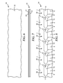
- Figures 1 and 2 show a strip of web 1 with parallel side edges from which fasteners according to the present invention may be produced.
- the web 1 comprises a flexible planar backing 2, which is made of a flexible thermoplastic resin, in particular resiliently flexible thermoplastic resin.
- the upper side and the lower side of the backing 2 may both be provided with a fastening element 3 and 4 each chosen independently from each other from a group comprising hook members of a hook-and-loop fastener, loop members of a hook-and-loop fastener or an adhesive coat.
- the fastening element 3 on the upper side of the backing 2 may be an adhesive coat, which may be covered by a release liner even though not shown here, and the fastening element 4 on the lower side of the backing 2 comprises a plurality of hook members of a hook-and-loop fastener, each hook member having a stem portion and may have a head portion, wherein the hook members are capable of being engaged with corresponding loop members of a hook-and-loop fastener or directly with garment like underwear.
- the web 1 can be supplied in roll form.
- Figure 3 shows a web of fasteners 5, according to a first embodiment of the present invention, which can be produced from the precursor web shown in Figures 1 and 2 by means of die cuttingor the like whereby the fasteners remain severably connected via bridging segments 11. Accordingly, also the web of fasteners 5 comprises the backing 2, the fastening element 3 and the optional fastening element 4.
- the web of fasteners 5 comprises a plurality of successively arranged fasteners 6, wherein each fastener 6 consists of one generally Y-shaped one-piece section.
- This Y-shaped one-piece section is defined by two opposing arms 7 and 8 which are separated from each other by a recess 9, and by a third arm 10 joined to the two opposing arms 7 and 8 and extending away from said recess 9, wherein the shape and size of said third arm 10 correspond to the shape and size of said recess 9.
- the arms 7 and 8 extend parallel to each other, and the recess 9 as well as the third arm 10 have a generally rectangular contour.
- Each fastener 6 is completely cut out from the web 1 apart from bridging segments 11, which connect adjacent fastener 6 with each other, so that the web of fasteners 5 still forms a continuous strip.
- the bridging elements can be formed, for example, by perforations or other weakening lines.
- FIG 4 shows a web of fasteners 12, according to a second embodiment of the present invention, which is made from the web 1 in Figures 1 and 2 by means of die-cutting or the like. Accordingly, also the web of fasteners 12 comprises a backing 2, a fastening element 3 and an optional fastening element 4. Similar to the web of fasteners 5 in Figure 3 the web of fasteners 12 in Figure 4 comprises a plurality of successively arranged fasteners 13, wherein each fastener 13 consists of a single generally Y-shaped one-piece section.
- Each generally Y-shaped one-piece section is defined by two opposing arms 14 and 15, which are separated from each other by a recess 16, and by a third arm 17 joined to the two opposing arms 14 and 15 and extending away from the recess 16, wherein the shape and size of said third arm 17 correspond to the shape and the size of the recess 16.
- the arms 14 and 15 extend parallel to each other.
- the recess 16 as well as the arm 17 generally essentially have a key-hole type contour wherein the bottom of the recess 16 as well as the free corresponding end of the third arm 17 comprise a widened portion 18 of generally circular shape as shown in the figures.
- Each fastener 13 is completely cut out apart from bridging segments 19, which connect adjacently arranged fasteners 13 with each other.
- FIG. 5 shows a web of fasteners 20, according to a third embodiment of the present invention, which is made from the web 1 in Figures 1 and 2 by means of die cutting or the like. Accordingly the web of fasteners 20 also comprises a backing 2 as well as a fastening element 3 and an optional fastening element 4.
- the web of fasteners 20 has a plurality of successively arranged fasteners, wherein each fastener 21 consists of two generally Y-shaped sections formed as single piece.
- the first Y-shaped section is defined by two opposing arms 22 and 23, which are separated from each other by a recess 24, and by a third arm 25 joined to the two opposing arms 22 and 23 and extending away from said recess 24, wherein the shape and size of said third arm 25 correspond to the shape and size of said recess 24.
- the second Y-shaped section is defined by two opposing arms 23 and 26, which are also separated from each other by a recess 27, as well as by an arm 28 joined to the two opposing arms 22 and 23 and extending away from said recess 27, wherein the shape and size of said arm 28 correspond to the shape and size of said recess 27.
- one of the opposing arms of the first Y-shaped section also forms one of the opposing arms of the adjacent Y-shaped section, namely the arm 23.
- the fasteners 21 are completely cut out apart from bridging segments 29, which connect adjacent fasteners 21 with each other.
- Figures 6 and 7 show a web 30 comprising a flexible planar backing 31 made of a flexible thermoplastic resin, in particular resiliently flexible thermoplastic resin.
- the backing 31 is provided on its upper side and on its lower side with fastening elements 32 and 33, each chosen from the group comprising hook members of a hook-and-loop fastener, loop members of a hook-and-loop fastener or an adhesive coat.
- the side edges of the web 30 may not be straight lines but have a regular or irregular curved form such as a sinusoidal form and/or regular or irregular polygonal form such as saw-tooth or zig-zag form.
- FIG 8 shows a web of fasteners 34, according to a fourth embodiment of the present invention, which is made from the web 30 in Figures 6 and 7 .
- the web of fasteners 34 comprises a plurality of successively arranged fasteners 36.
- the form and shape of each fastening element 36 generally correspond to the shape and size of the fasteners 6 in Figure 3 , for which reason same reference numerals are used for corresponding features.
- the sides 7, 8 of the fastener 36 are waved due to the wave form of the starting web 30 in Figure 6 .
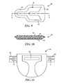
- Figures 9 and 10 show an absorbent article 38 according to a first embodiment of the present invention, which defines a male incontinence guard.
- the absorbent article 38 comprises a body side liner 39 (not shown), an outer liner 40 and an absorbent pad 41 disposed therebetween.
- the absorbent article 38 has a narrow portion 42 and a wide portion 43 when laid out flat. The wide portion 43 is worn closer to the waist of the user, while the narrow portion 42 is positioned more towards the area between the legs of the user. This shape of the absorbent article 38 is comfortable for the wearer and offers liquid retention benefits.
- On the outer liner 40 a fastener 6 of the type shown in Figure 3 is attached.
- an adhesive fastening element 4 after peeling off an optional release liner, is affixed to the outer liner 40, such that a hook-type fastening element 3 faces outwards in order to removably fix the absorbent article 38 in position on the underpants of a wearer.
- FIG 11 shows another absorbent article 44 according to an embodiment of the present invention, which defines a conventional diaper for an infant.
- the general configuration of such a diaper is already known in the art, wherefore it is not described in detail here.
- Fasteners 6 of the kind shown in Figure 3 are affixed to elastic strips 45 of the diaper 44, such that hook members of the fastening elements 4 face outward to be brought into contact with corresponding loop members 46 affixed to the absorbent article 44. Accordingly, the diaper can be opened and closed by means of the hook-and-loop fasteners.
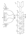
- Figure 12 shows a diaper as a further embodiment of an absorbent article 44 according to the present invention. It is similar to the embodiment of Fig. 11 but differs in that an elastic fastening tap 47 is attached to the elastic strips 45 wherein the fastener 6 is attached to both the elastic strips 45 and the additional fastening tab 47.
- Fig. 13 illustrates the method of separating individual fasteners 6 from the web 1 of fasteners 6.
- the fasteners 6 are completely cut out apart from severable bridging segments 11.
- the fasteners 6 are individualized by breaking up the bridging elements 11 thereby severing the individual fastener 6 from the remainder of the web 1.
Landscapes
- Health & Medical Sciences (AREA)
- Engineering & Computer Science (AREA)
- General Health & Medical Sciences (AREA)
- Public Health (AREA)
- Heart & Thoracic Surgery (AREA)
- Vascular Medicine (AREA)
- Life Sciences & Earth Sciences (AREA)
- Animal Behavior & Ethology (AREA)
- Epidemiology (AREA)
- Biomedical Technology (AREA)
- Veterinary Medicine (AREA)
- Manufacturing & Machinery (AREA)
- Mechanical Engineering (AREA)
- Absorbent Articles And Supports Therefor (AREA)
- Orthopedics, Nursing, And Contraception (AREA)
- Slide Fasteners, Snap Fasteners, And Hook Fasteners (AREA)
Abstract
Description
- The present invention relates to fasteners, webs comprising a plurality of such fasteners which are successively arranged, and absorbent articles comprising at least one of such fasteners.
- Some male incontinence guards, such as those sold under the trade name Tena for Men (TM) level 1 or
level 2, have a body side liner, an outer liner and an absorbent pad disposed therebetween. The guard is generally triangular shaped when laid out flat. The base of the triangle is worn closer to the waist of the user, while the point of the triangle is positioned more towards the area between the legs of the user. This shape of article is more comfortable for the wearer and offers liquid retention benefits. The outer liner has fastening elements in the form of rectangular strips of adhesive tape attached to it that are covered by a release liner. To wear, the release liner is peeled away and the adhesive strips serve to removably fix the guard in position on the underpants of the wearer. Alternative shapes for the adhesive tapes may be desirable that provide improved fastening coverage for such triangular-shaped absorbent articles. Such alternative shapes would optimally maintain material use efficiency (lack of waste trimmings) of rectangular strips. - It has been found that it may be desirable to form a Y-shape fastener or the like. Such a Y-shape is defined by two opposing arms which are separated from each other by a recess, and by a third arm extending in extension of and away from said recess. Such a Y-shape will provide coverage of the corner portions of a triangle shaped guard by a single fastening element.
- A problem with cutting a complex shape such as a Y-shape or the like is that it involves a significant amount of waste material as a result of a nesting mismatch in adjacent elements. Stamping such complex shapes out of a web of material results in too much waste for production efficiency purposes. Accordingly, it would be desirable to provide a fastener that can be produced with reduced waste.
- In order to solve this object, the present invention provides a fastener comprising a flexible planar backing and a fastening element on its upper side and/or on its lower side, wherein the fastener has at least one generally Y-shaped one-piece section defined by two opposing arms, which are separated from each other by a recess, and by a third arm joined to the two opposing arms and extending away from said recess, wherein the shape and size of said third arm correspond to the shape and size of said recess. This construction allows for successive fasteners to be stamped out of a web of material without producing any waste.
- The outer edges of the opposing arms preferably extend parallel to each other. Accordingly, the elements can be stamped out of a strip or roll of web material having parallel side edges.
- The recess as well as the third arm may have any shape, e. g. a generally rectangular, or triangular, polygonal, generally curved such as, e.g., semi-circular, and/or exhibit a more complex contour. This reduces the complexity of the stamping tool.
- The bottom of the recess, as well as the free corresponding end of the third arm, may comprise a widened portion. Such a widened portion improves the attachment of the free end of the third arm of fastener to an article, such as an absorbent article.
- According to one aspect of the present invention the backing is made of flexible thermoplastic resin, in particular resiliently flexible thermoplastic resin so that the fastener can easily conform to the shape of the article to which the fastening element is affixed.
- Preferably each fastener element is chosen from the group comprising hook members of a hook and/loop fastener, loop members of a hook-and-loop fastener and/or an adhesive coating.
- According to one aspect of the present invention the fastener consists of a plurality of adjacently arranged Y-shaped sections formed as a single piece, wherein one of the opposing arms of a first Y-shaped section also forms one of the opposing arms of an adjacent Y-shaped section.
- Moreover, the present invention provides a web comprising a plurality of successively arranged fasteners of the above-mentioned type, wherein the fasteners are completely cut out apart from bridging segments which connect adjacent fasteners with each other. Such webs can be delivered to a producer of articles, such as absorbent articles, where the single fasteners are severed from the web and fixed to the articles.
- In one embodiment, the web is in the form of a strip. This simplifies further processing.
- In an alternative embodiment, the web is in the form of a roll in order to facilitate the transport and packaging of the web.
- Furthermore, the present invention provides an absorbent article comprising at least one fastener of the above-mentioned type.
- Moreover, the present invention relates to a method of providing a plurality of individual fasteners according to the present invention comprising the steps of
- providing a web of pre-cut fasteners which are completely cut out apart from severable bridging elements, and
- individualizing said fasteners from said web by severing said bridges.
- The present invention also relates to a method of making absorbent articles comprising the steps of
- providing a web of absorbent articles,
- providing a plurality of fasteners according to the present invention, and
- applying said fasteners to said absorbent articles.
- The present invention provides for an essentially waste-less method of providing integral fasteners. The fasteners of the present invention exhibit when applied to absorbent articles such as diapers, feminine hygiene articles such as feminine napkins or male incontinence guards, respectively, an improved stress distribution and/or an improved flexibility thereby distinctly improving the performance of the absorbent article.
-
- Figure 1
- is a plan view of a web, from which a web of fasteners according to an embodiment of the present invention is produced;
- Figure 2
- is a side view of the web in
Figure 1 ; - Figure 3
- is a web of fasteners, according to a first embodiment of the present invention, produced from the web in
Figures 1 and 2 ; - Figure 4
- is a plan view of a web of fasteners, according to a second embodiment of the present invention, produced from the web in
Figures 1 and 2 ; - Figure 5
- is a plan view of a web of fasteners, according to a third embodiment of the present invention, produced from the web in
Figures 1 and 2 ; - Figure 6
- is a plan view of another web;
- Figure 7
- is a side view of the web in
Figure 6 ; - Figure 8
- is a plan view of a web of fasteners, according to a fourth embodiment of the present invention, produced from the web in
Figures 6 and 7 ; - Figure 9
- is a bottom view of an absorbent article according to an embodiment of the present invention;
- Figure 10
- is a sectional side view of the absorbent article in
Figure 9 and - Figure 11
- is a front view of another absorbent article according to the present invention.
- Figure 12
- is a front view of another embodiment of an absorbent article according to the present invention.
- Figure 13
- is a top view on a web according to the present invention illustrating a process of individualizing fasteners from said web.
- Detailed description of preferred embodiments of the invention
-
Figures 1 and 2 show a strip of web 1 with parallel side edges from which fasteners according to the present invention may be produced. The web 1 comprises a flexibleplanar backing 2, which is made of a flexible thermoplastic resin, in particular resiliently flexible thermoplastic resin. The upper side and the lower side of thebacking 2 may both be provided with afastening element 3 and 4 each chosen independently from each other from a group comprising hook members of a hook-and-loop fastener, loop members of a hook-and-loop fastener or an adhesive coat. For example, thefastening element 3 on the upper side of thebacking 2 may be an adhesive coat, which may be covered by a release liner even though not shown here, and the fastening element 4 on the lower side of thebacking 2 comprises a plurality of hook members of a hook-and-loop fastener, each hook member having a stem portion and may have a head portion, wherein the hook members are capable of being engaged with corresponding loop members of a hook-and-loop fastener or directly with garment like underwear. The web 1 can be supplied in roll form. -
Figure 3 shows a web offasteners 5, according to a first embodiment of the present invention, which can be produced from the precursor web shown inFigures 1 and 2 by means of die cuttingor the like whereby the fasteners remain severably connected via bridgingsegments 11. Accordingly, also the web offasteners 5 comprises thebacking 2, thefastening element 3 and the optional fastening element 4. The web offasteners 5 comprises a plurality of successively arrangedfasteners 6, wherein eachfastener 6 consists of one generally Y-shaped one-piece section. This Y-shaped one-piece section is defined by two opposingarms recess 9, and by athird arm 10 joined to the two opposingarms recess 9, wherein the shape and size of saidthird arm 10 correspond to the shape and size of saidrecess 9. Thearms recess 9 as well as thethird arm 10 have a generally rectangular contour. Eachfastener 6 is completely cut out from the web 1 apart from bridgingsegments 11, which connectadjacent fastener 6 with each other, so that the web offasteners 5 still forms a continuous strip. The bridging elements can be formed, for example, by perforations or other weakening lines. -
Figure 4 shows a web offasteners 12, according to a second embodiment of the present invention, which is made from the web 1 inFigures 1 and 2 by means of die-cutting or the like. Accordingly, also the web offasteners 12 comprises abacking 2, afastening element 3 and an optional fastening element 4. Similar to the web offasteners 5 inFigure 3 the web offasteners 12 inFigure 4 comprises a plurality of successively arrangedfasteners 13, wherein eachfastener 13 consists of a single generally Y-shaped one-piece section. Each generally Y-shaped one-piece section is defined by two opposingarms recess 16, and by athird arm 17 joined to the two opposingarms recess 16, wherein the shape and size of saidthird arm 17 correspond to the shape and the size of therecess 16. Thearms recess 16 as well as thearm 17 generally essentially have a key-hole type contour wherein the bottom of therecess 16 as well as the free corresponding end of thethird arm 17 comprise a widenedportion 18 of generally circular shape as shown in the figures. Other shapes such as essentially rectangular, triangular, polygonal, generally curved such as, e.g., semi-circular and combinations of the aforementioned shapes are also conceivable. Eachfastener 13 is completely cut out apart from bridgingsegments 19, which connect adjacently arrangedfasteners 13 with each other. -
Figure 5 shows a web offasteners 20, according to a third embodiment of the present invention, which is made from the web 1 inFigures 1 and 2 by means of die cutting or the like. Accordingly the web offasteners 20 also comprises abacking 2 as well as afastening element 3 and an optional fastening element 4. The web offasteners 20 has a plurality of successively arranged fasteners, wherein eachfastener 21 consists of two generally Y-shaped sections formed as single piece. The first Y-shaped section is defined by two opposingarms recess 24, and by athird arm 25 joined to the two opposingarms recess 24, wherein the shape and size of saidthird arm 25 correspond to the shape and size of saidrecess 24. The second Y-shaped section is defined by two opposingarms recess 27, as well as by anarm 28 joined to the two opposingarms recess 27, wherein the shape and size of saidarm 28 correspond to the shape and size of saidrecess 27. Accordingly, one of the opposing arms of the first Y-shaped section also forms one of the opposing arms of the adjacent Y-shaped section, namely thearm 23. Thefasteners 21 are completely cut out apart from bridgingsegments 29, which connectadjacent fasteners 21 with each other. - It should be noted that the number of Y-shaped sections forming one
fastener 21 can be varied as needed. -
Figures 6 and 7 show aweb 30 comprising a flexibleplanar backing 31 made of a flexible thermoplastic resin, in particular resiliently flexible thermoplastic resin. Thebacking 31 is provided on its upper side and on its lower side withfastening elements Figures 1 and 2 , the side edges of theweb 30 may not be straight lines but have a regular or irregular curved form such as a sinusoidal form and/or regular or irregular polygonal form such as saw-tooth or zig-zag form. -
Figure 8 shows a web offasteners 34, according to a fourth embodiment of the present invention, which is made from theweb 30 inFigures 6 and 7 . The web offasteners 34 comprises a plurality of successively arrangedfasteners 36. The form and shape of eachfastening element 36 generally correspond to the shape and size of thefasteners 6 inFigure 3 , for which reason same reference numerals are used for corresponding features. However, in contrast to thefastener 6 shown inFigure 3 , thesides fastener 36 are waved due to the wave form of the startingweb 30 inFigure 6 . -
Figures 9 and 10 show anabsorbent article 38 according to a first embodiment of the present invention, which defines a male incontinence guard. Theabsorbent article 38 comprises a body side liner 39 (not shown), anouter liner 40 and anabsorbent pad 41 disposed therebetween. Theabsorbent article 38 has anarrow portion 42 and awide portion 43 when laid out flat. Thewide portion 43 is worn closer to the waist of the user, while thenarrow portion 42 is positioned more towards the area between the legs of the user. This shape of theabsorbent article 38 is comfortable for the wearer and offers liquid retention benefits. On the outer liner 40 afastener 6 of the type shown inFigure 3 is attached. More precisely, an adhesive fastening element 4, after peeling off an optional release liner, is affixed to theouter liner 40, such that a hook-type fastening element 3 faces outwards in order to removably fix theabsorbent article 38 in position on the underpants of a wearer. -
Figure 11 shows anotherabsorbent article 44 according to an embodiment of the present invention, which defines a conventional diaper for an infant. The general configuration of such a diaper is already known in the art, wherefore it is not described in detail here.Fasteners 6 of the kind shown inFigure 3 are affixed toelastic strips 45 of thediaper 44, such that hook members of the fastening elements 4 face outward to be brought into contact withcorresponding loop members 46 affixed to theabsorbent article 44. Accordingly, the diaper can be opened and closed by means of the hook-and-loop fasteners. -
Figure 12 shows a diaper as a further embodiment of anabsorbent article 44 according to the present invention. It is similar to the embodiment ofFig. 11 but differs in that anelastic fastening tap 47 is attached to theelastic strips 45 wherein thefastener 6 is attached to both theelastic strips 45 and theadditional fastening tab 47. -
Fig. 13 illustrates the method of separatingindividual fasteners 6 from the web 1 offasteners 6. In the web 1 thefasteners 6 are completely cut out apart fromseverable bridging segments 11. Thefasteners 6 are individualized by breaking up thebridging elements 11 thereby severing theindividual fastener 6 from the remainder of the web 1.
Claims (12)
- A fastener (6; 13; 21, 36) comprising a flexible planar backing (2; 31) provided with a fastener element (3, 4; 32, 33) on its upper side and/or on its lower side, wherein the fastener (6; 13; 21; 36) consists of at least one generally Y-shaped one-piece section defined by two opposing arms (7, 8; 14, 15; 22, 23, 26), which are separated from each other by a recess (9; 16; 24, 27), and by a third arm (10; 17; 25, 28) joined to the two opposing arms (7, 8; 14, 15; 22, 23, 26) and extending away from said recess (9; 16; 24, 27), wherein the shape and size of said third arm (10; 17; 25, 28) correspond to the shape and size of said recess (9; 16; 24; 27).
- The fastener (6; 13; 21) according to claim 1, wherein the outer edges of the opposing arms (7, 8; 14, 15; 22, 23, 26) extend parallel to each other.
- The fastener (6; 13; 21; 36) according to one of the foregoing claims, wherein the recess (9; 16; 24, 27) as well as the third arm (10; 17; 25, 28) generally have a generally rectangular contour.
- The fastener (13) according to one of the foregoing claims, wherein the bottom of the recess (16) as well as the free corresponding end of the third arm (17) comprise a widened portion (18).
- The fastener (6; 13; 21; 36) according to one of the foregoing claims, wherein the backing (2; 31) is made of a flexible thermoplastic resin.
- The fastener (6; 13; 21; 36) according to one of the foregoing claims, wherein each fastening element (3, 4; 32, 33) is selected from the group comprising hook members of a hook-and-loop fastener, loop members of a hook-and-loop fastener and an adhesive coat.
- The fastener (21) according to one of the foregoing claims, wherein the element consists of a plurality of adjacently arranged Y-shaped sections formed as a single piece, wherein one of the opposing arms (23) of a first Y-shaped section also forms one of the opposing arms (23) of an adjacent Y-shaped section.
- A web of fasteners (5; 12; 20; 34) comprising a plurality of successively arranged fasteners (6; 13; 21; 36) according to one of the foregoing claims, wherein the fasteners (6; 13; 21; 36) are completely cut out apart from severable bridging segments (11; 19; 29), which connect adjacent fasteners (6; 13; 21; 36) with each other.
- The web of fasteners (5; 12; 20; 34) according to claim 8, wherein the web is a strip.
- A roll of fasteners (5; 12; 20; 34) according to claims 8 and 9.
- Absorbent article (38; 44) comprising at least one fastener according to one of the claims 1 to 7.
- Method of providing a plurality of individual fasteners according to any of claims 1 -7, the method comprising the steps of- providing a web of fasteners according to any of claims 8 to 10,and- individualizing said fasteners by severing them from said web. 13. Method of making absorbent articles comprising at least one fastener according to any of claims 1 - 7, the method comprising the steps of- providing a web of absorbent articles,- providing a plurality of fasteners according to any of claims 1 - 7, and- applying said fasteners to said absorbent articles.
Priority Applications (4)
| Application Number | Priority Date | Filing Date | Title |
|---|---|---|---|
| EP12176222.3A EP2684547B1 (en) | 2012-07-12 | 2012-07-12 | Fasteners |
| PL12176222T PL2684547T3 (en) | 2012-07-12 | 2012-07-12 | Fasteners |
| US14/414,257 US9789015B2 (en) | 2012-07-12 | 2013-07-12 | Fasteners |
| PCT/US2013/050201 WO2014011957A1 (en) | 2012-07-12 | 2013-07-12 | Fasteners |
Applications Claiming Priority (1)
| Application Number | Priority Date | Filing Date | Title |
|---|---|---|---|
| EP12176222.3A EP2684547B1 (en) | 2012-07-12 | 2012-07-12 | Fasteners |
Publications (2)
| Publication Number | Publication Date |
|---|---|
| EP2684547A1 true EP2684547A1 (en) | 2014-01-15 |
| EP2684547B1 EP2684547B1 (en) | 2017-11-08 |
Family
ID=48914424
Family Applications (1)
| Application Number | Title | Priority Date | Filing Date |
|---|---|---|---|
| EP12176222.3A Not-in-force EP2684547B1 (en) | 2012-07-12 | 2012-07-12 | Fasteners |
Country Status (4)
| Country | Link |
|---|---|
| US (1) | US9789015B2 (en) |
| EP (1) | EP2684547B1 (en) |
| PL (1) | PL2684547T3 (en) |
| WO (1) | WO2014011957A1 (en) |
Citations (3)
| Publication number | Priority date | Publication date | Assignee | Title |
|---|---|---|---|---|
| EP1452158A1 (en) * | 2003-02-28 | 2004-09-01 | 3M Innovative Properties Company | Method of preparing closure components suitable for use in diapers |
| EP1902695A1 (en) * | 2006-09-21 | 2008-03-26 | Tyco Healthcare Retail Services AG | Absorbent articles, fastener ears for absorbent articles, and processes for making same |
| WO2012015025A1 (en) * | 2010-07-30 | 2012-02-02 | 大王製紙株式会社 | Absorbent pad and absorptive article |
Family Cites Families (4)
| Publication number | Priority date | Publication date | Assignee | Title |
|---|---|---|---|---|
| US207253A (en) * | 1878-08-20 | Improvement in corset-clasps | ||
| US198097A (en) * | 1877-12-11 | Improvement in cockeyes | ||
| US3620180A (en) * | 1969-10-20 | 1971-11-16 | Waldes Kohinoor Inc | Readily engageable and disengageable fasteners |
| US4713864A (en) * | 1987-03-23 | 1987-12-22 | Hess Herman A | Separable fastener with sliding sleeve |
-
2012
- 2012-07-12 PL PL12176222T patent/PL2684547T3/en unknown
- 2012-07-12 EP EP12176222.3A patent/EP2684547B1/en not_active Not-in-force
-
2013
- 2013-07-12 US US14/414,257 patent/US9789015B2/en not_active Expired - Fee Related
- 2013-07-12 WO PCT/US2013/050201 patent/WO2014011957A1/en not_active Ceased
Patent Citations (3)
| Publication number | Priority date | Publication date | Assignee | Title |
|---|---|---|---|---|
| EP1452158A1 (en) * | 2003-02-28 | 2004-09-01 | 3M Innovative Properties Company | Method of preparing closure components suitable for use in diapers |
| EP1902695A1 (en) * | 2006-09-21 | 2008-03-26 | Tyco Healthcare Retail Services AG | Absorbent articles, fastener ears for absorbent articles, and processes for making same |
| WO2012015025A1 (en) * | 2010-07-30 | 2012-02-02 | 大王製紙株式会社 | Absorbent pad and absorptive article |
Also Published As
| Publication number | Publication date |
|---|---|
| EP2684547B1 (en) | 2017-11-08 |
| US20150173981A1 (en) | 2015-06-25 |
| WO2014011957A1 (en) | 2014-01-16 |
| PL2684547T3 (en) | 2018-03-30 |
| US9789015B2 (en) | 2017-10-17 |
Similar Documents
| Publication | Publication Date | Title |
|---|---|---|
| TWI386193B (en) | Strip of male fastening means, patch cut therefrom, fastening tape tab comprising such patch, and method of making such strip | |
| US8262637B2 (en) | Fastening tape for a hygiene item, diaper,method of closing a diaper, tape material and winding of a tape material | |
| CN103249326B (en) | Fastening tab and method of preparing said fastening tab | |
| AU2002325264B2 (en) | Hygiene article with fastening elements | |
| AU606249B2 (en) | Disposable diaper with improved hook and loop fastener system | |
| EP2667832B1 (en) | An absorbent article comprising a shaped element and a method of making such | |
| US7820003B2 (en) | Method for producing diaper | |
| US20040172792A1 (en) | Hook fastener engaging zones | |
| CN101237839B (en) | Composite web, disposable diaper and method of manufacture | |
| EP2641574B1 (en) | Method and apparatus for manufacturing disposable worn article | |
| US20160174643A1 (en) | Wardrobe tape and method of using same | |
| US20090071600A1 (en) | Method for producing disposable worn article | |
| EP2684547B1 (en) | Fasteners | |
| US10729594B2 (en) | Feminine hygiene products and apparatus and methods for making disposable products | |
| US8247636B2 (en) | Fastening tape for a hygiene item, and method for producing a fastening tape for a hygiene item | |
| AU2014250665A1 (en) | Easily removed identification bands | |
| JP3114623U (en) | Meal napkin | |
| EP2574321A1 (en) | Disposable Diaper For Adults Having A Non-Woven Closure Tape | |
| JP2008012332A (en) | Manufacturing method of long sheet member for fastening tape manufacturing |
Legal Events
| Date | Code | Title | Description |
|---|---|---|---|
| PUAI | Public reference made under article 153(3) epc to a published international application that has entered the european phase |
Free format text: ORIGINAL CODE: 0009012 |
|
| AK | Designated contracting states |
Kind code of ref document: A1 Designated state(s): AL AT BE BG CH CY CZ DE DK EE ES FI FR GB GR HR HU IE IS IT LI LT LU LV MC MK MT NL NO PL PT RO RS SE SI SK SM TR |
|
| AX | Request for extension of the european patent |
Extension state: BA ME |
|
| 17P | Request for examination filed |
Effective date: 20140613 |
|
| RBV | Designated contracting states (corrected) |
Designated state(s): AL AT BE BG CH CY CZ DE DK EE ES FI FR GB GR HR HU IE IS IT LI LT LU LV MC MK MT NL NO PL PT RO RS SE SI SK SM TR |
|
| 17Q | First examination report despatched |
Effective date: 20160411 |
|
| REG | Reference to a national code |
Ref country code: DE Ref legal event code: R079 Ref document number: 602012039423 Country of ref document: DE Free format text: PREVIOUS MAIN CLASS: A61F0013150000 Ipc: A44B0018000000 |
|
| GRAP | Despatch of communication of intention to grant a patent |
Free format text: ORIGINAL CODE: EPIDOSNIGR1 |
|
| STAA | Information on the status of an ep patent application or granted ep patent |
Free format text: STATUS: GRANT OF PATENT IS INTENDED |
|
| RIC1 | Information provided on ipc code assigned before grant |
Ipc: A61F 13/56 20060101ALI20170504BHEP Ipc: A44B 18/00 20060101AFI20170504BHEP Ipc: A61F 13/62 20060101ALI20170504BHEP Ipc: A61F 13/15 20060101ALI20170504BHEP |
|
| INTG | Intention to grant announced |
Effective date: 20170524 |
|
| GRAS | Grant fee paid |
Free format text: ORIGINAL CODE: EPIDOSNIGR3 |
|
| GRAA | (expected) grant |
Free format text: ORIGINAL CODE: 0009210 |
|
| STAA | Information on the status of an ep patent application or granted ep patent |
Free format text: STATUS: THE PATENT HAS BEEN GRANTED |
|
| AK | Designated contracting states |
Kind code of ref document: B1 Designated state(s): AL AT BE BG CH CY CZ DE DK EE ES FI FR GB GR HR HU IE IS IT LI LT LU LV MC MK MT NL NO PL PT RO RS SE SI SK SM TR |
|
| REG | Reference to a national code |
Ref country code: GB Ref legal event code: FG4D |
|
| REG | Reference to a national code |
Ref country code: CH Ref legal event code: EP Ref country code: AT Ref legal event code: REF Ref document number: 943330 Country of ref document: AT Kind code of ref document: T Effective date: 20171115 |
|
| REG | Reference to a national code |
Ref country code: IE Ref legal event code: FG4D |
|
| REG | Reference to a national code |
Ref country code: DE Ref legal event code: R096 Ref document number: 602012039423 Country of ref document: DE |
|
| REG | Reference to a national code |
Ref country code: SE Ref legal event code: TRGR |
|
| REG | Reference to a national code |
Ref country code: NL Ref legal event code: MP Effective date: 20171108 |
|
| REG | Reference to a national code |
Ref country code: LT Ref legal event code: MG4D |
|
| REG | Reference to a national code |
Ref country code: AT Ref legal event code: MK05 Ref document number: 943330 Country of ref document: AT Kind code of ref document: T Effective date: 20171108 |
|
| PG25 | Lapsed in a contracting state [announced via postgrant information from national office to epo] |
Ref country code: ES Free format text: LAPSE BECAUSE OF FAILURE TO SUBMIT A TRANSLATION OF THE DESCRIPTION OR TO PAY THE FEE WITHIN THE PRESCRIBED TIME-LIMIT Effective date: 20171108 Ref country code: FI Free format text: LAPSE BECAUSE OF FAILURE TO SUBMIT A TRANSLATION OF THE DESCRIPTION OR TO PAY THE FEE WITHIN THE PRESCRIBED TIME-LIMIT Effective date: 20171108 Ref country code: LT Free format text: LAPSE BECAUSE OF FAILURE TO SUBMIT A TRANSLATION OF THE DESCRIPTION OR TO PAY THE FEE WITHIN THE PRESCRIBED TIME-LIMIT Effective date: 20171108 Ref country code: NO Free format text: LAPSE BECAUSE OF FAILURE TO SUBMIT A TRANSLATION OF THE DESCRIPTION OR TO PAY THE FEE WITHIN THE PRESCRIBED TIME-LIMIT Effective date: 20180208 Ref country code: NL Free format text: LAPSE BECAUSE OF FAILURE TO SUBMIT A TRANSLATION OF THE DESCRIPTION OR TO PAY THE FEE WITHIN THE PRESCRIBED TIME-LIMIT Effective date: 20171108 |
|
| PG25 | Lapsed in a contracting state [announced via postgrant information from national office to epo] |
Ref country code: LV Free format text: LAPSE BECAUSE OF FAILURE TO SUBMIT A TRANSLATION OF THE DESCRIPTION OR TO PAY THE FEE WITHIN THE PRESCRIBED TIME-LIMIT Effective date: 20171108 Ref country code: AT Free format text: LAPSE BECAUSE OF FAILURE TO SUBMIT A TRANSLATION OF THE DESCRIPTION OR TO PAY THE FEE WITHIN THE PRESCRIBED TIME-LIMIT Effective date: 20171108 Ref country code: GR Free format text: LAPSE BECAUSE OF FAILURE TO SUBMIT A TRANSLATION OF THE DESCRIPTION OR TO PAY THE FEE WITHIN THE PRESCRIBED TIME-LIMIT Effective date: 20180209 Ref country code: RS Free format text: LAPSE BECAUSE OF FAILURE TO SUBMIT A TRANSLATION OF THE DESCRIPTION OR TO PAY THE FEE WITHIN THE PRESCRIBED TIME-LIMIT Effective date: 20171108 Ref country code: BG Free format text: LAPSE BECAUSE OF FAILURE TO SUBMIT A TRANSLATION OF THE DESCRIPTION OR TO PAY THE FEE WITHIN THE PRESCRIBED TIME-LIMIT Effective date: 20180208 Ref country code: IS Free format text: LAPSE BECAUSE OF FAILURE TO SUBMIT A TRANSLATION OF THE DESCRIPTION OR TO PAY THE FEE WITHIN THE PRESCRIBED TIME-LIMIT Effective date: 20180308 Ref country code: HR Free format text: LAPSE BECAUSE OF FAILURE TO SUBMIT A TRANSLATION OF THE DESCRIPTION OR TO PAY THE FEE WITHIN THE PRESCRIBED TIME-LIMIT Effective date: 20171108 |
|
| PG25 | Lapsed in a contracting state [announced via postgrant information from national office to epo] |
Ref country code: CZ Free format text: LAPSE BECAUSE OF FAILURE TO SUBMIT A TRANSLATION OF THE DESCRIPTION OR TO PAY THE FEE WITHIN THE PRESCRIBED TIME-LIMIT Effective date: 20171108 Ref country code: CY Free format text: LAPSE BECAUSE OF FAILURE TO SUBMIT A TRANSLATION OF THE DESCRIPTION OR TO PAY THE FEE WITHIN THE PRESCRIBED TIME-LIMIT Effective date: 20171108 Ref country code: EE Free format text: LAPSE BECAUSE OF FAILURE TO SUBMIT A TRANSLATION OF THE DESCRIPTION OR TO PAY THE FEE WITHIN THE PRESCRIBED TIME-LIMIT Effective date: 20171108 Ref country code: DK Free format text: LAPSE BECAUSE OF FAILURE TO SUBMIT A TRANSLATION OF THE DESCRIPTION OR TO PAY THE FEE WITHIN THE PRESCRIBED TIME-LIMIT Effective date: 20171108 Ref country code: SK Free format text: LAPSE BECAUSE OF FAILURE TO SUBMIT A TRANSLATION OF THE DESCRIPTION OR TO PAY THE FEE WITHIN THE PRESCRIBED TIME-LIMIT Effective date: 20171108 |
|
| REG | Reference to a national code |
Ref country code: DE Ref legal event code: R097 Ref document number: 602012039423 Country of ref document: DE |
|
| PG25 | Lapsed in a contracting state [announced via postgrant information from national office to epo] |
Ref country code: IT Free format text: LAPSE BECAUSE OF FAILURE TO SUBMIT A TRANSLATION OF THE DESCRIPTION OR TO PAY THE FEE WITHIN THE PRESCRIBED TIME-LIMIT Effective date: 20171108 Ref country code: RO Free format text: LAPSE BECAUSE OF FAILURE TO SUBMIT A TRANSLATION OF THE DESCRIPTION OR TO PAY THE FEE WITHIN THE PRESCRIBED TIME-LIMIT Effective date: 20171108 Ref country code: SM Free format text: LAPSE BECAUSE OF FAILURE TO SUBMIT A TRANSLATION OF THE DESCRIPTION OR TO PAY THE FEE WITHIN THE PRESCRIBED TIME-LIMIT Effective date: 20171108 |
|
| PGFP | Annual fee paid to national office [announced via postgrant information from national office to epo] |
Ref country code: PL Payment date: 20180621 Year of fee payment: 7 |
|
| PLBE | No opposition filed within time limit |
Free format text: ORIGINAL CODE: 0009261 |
|
| STAA | Information on the status of an ep patent application or granted ep patent |
Free format text: STATUS: NO OPPOSITION FILED WITHIN TIME LIMIT |
|
| 26N | No opposition filed |
Effective date: 20180809 |
|
| PG25 | Lapsed in a contracting state [announced via postgrant information from national office to epo] |
Ref country code: SI Free format text: LAPSE BECAUSE OF FAILURE TO SUBMIT A TRANSLATION OF THE DESCRIPTION OR TO PAY THE FEE WITHIN THE PRESCRIBED TIME-LIMIT Effective date: 20171108 |
|
| REG | Reference to a national code |
Ref country code: DE Ref legal event code: R119 Ref document number: 602012039423 Country of ref document: DE |
|
| REG | Reference to a national code |
Ref country code: CH Ref legal event code: PL |
|
| GBPC | Gb: european patent ceased through non-payment of renewal fee |
Effective date: 20180712 |
|
| PG25 | Lapsed in a contracting state [announced via postgrant information from national office to epo] |
Ref country code: MC Free format text: LAPSE BECAUSE OF FAILURE TO SUBMIT A TRANSLATION OF THE DESCRIPTION OR TO PAY THE FEE WITHIN THE PRESCRIBED TIME-LIMIT Effective date: 20171108 Ref country code: LU Free format text: LAPSE BECAUSE OF NON-PAYMENT OF DUE FEES Effective date: 20180712 |
|
| REG | Reference to a national code |
Ref country code: BE Ref legal event code: MM Effective date: 20180731 |
|
| REG | Reference to a national code |
Ref country code: IE Ref legal event code: MM4A |
|
| PG25 | Lapsed in a contracting state [announced via postgrant information from national office to epo] |
Ref country code: LI Free format text: LAPSE BECAUSE OF NON-PAYMENT OF DUE FEES Effective date: 20180731 Ref country code: DE Free format text: LAPSE BECAUSE OF NON-PAYMENT OF DUE FEES Effective date: 20190201 Ref country code: IE Free format text: LAPSE BECAUSE OF NON-PAYMENT OF DUE FEES Effective date: 20180712 Ref country code: FR Free format text: LAPSE BECAUSE OF NON-PAYMENT OF DUE FEES Effective date: 20180731 Ref country code: CH Free format text: LAPSE BECAUSE OF NON-PAYMENT OF DUE FEES Effective date: 20180731 Ref country code: GB Free format text: LAPSE BECAUSE OF NON-PAYMENT OF DUE FEES Effective date: 20180712 |
|
| PG25 | Lapsed in a contracting state [announced via postgrant information from national office to epo] |
Ref country code: SE Free format text: LAPSE BECAUSE OF NON-PAYMENT OF DUE FEES Effective date: 20180713 Ref country code: BE Free format text: LAPSE BECAUSE OF NON-PAYMENT OF DUE FEES Effective date: 20180731 |
|
| PG25 | Lapsed in a contracting state [announced via postgrant information from national office to epo] |
Ref country code: MT Free format text: LAPSE BECAUSE OF NON-PAYMENT OF DUE FEES Effective date: 20180712 |
|
| PG25 | Lapsed in a contracting state [announced via postgrant information from national office to epo] |
Ref country code: TR Free format text: LAPSE BECAUSE OF FAILURE TO SUBMIT A TRANSLATION OF THE DESCRIPTION OR TO PAY THE FEE WITHIN THE PRESCRIBED TIME-LIMIT Effective date: 20171108 |
|
| PG25 | Lapsed in a contracting state [announced via postgrant information from national office to epo] |
Ref country code: PT Free format text: LAPSE BECAUSE OF FAILURE TO SUBMIT A TRANSLATION OF THE DESCRIPTION OR TO PAY THE FEE WITHIN THE PRESCRIBED TIME-LIMIT Effective date: 20171108 Ref country code: HU Free format text: LAPSE BECAUSE OF FAILURE TO SUBMIT A TRANSLATION OF THE DESCRIPTION OR TO PAY THE FEE WITHIN THE PRESCRIBED TIME-LIMIT; INVALID AB INITIO Effective date: 20120712 |
|
| PG25 | Lapsed in a contracting state [announced via postgrant information from national office to epo] |
Ref country code: MK Free format text: LAPSE BECAUSE OF NON-PAYMENT OF DUE FEES Effective date: 20171108 |
|
| PG25 | Lapsed in a contracting state [announced via postgrant information from national office to epo] |
Ref country code: AL Free format text: LAPSE BECAUSE OF FAILURE TO SUBMIT A TRANSLATION OF THE DESCRIPTION OR TO PAY THE FEE WITHIN THE PRESCRIBED TIME-LIMIT Effective date: 20171108 |
|
| PG25 | Lapsed in a contracting state [announced via postgrant information from national office to epo] |
Ref country code: PL Free format text: LAPSE BECAUSE OF NON-PAYMENT OF DUE FEES Effective date: 20190712 |