EP2684520B1 - Apparatus for generating laser - Google Patents
Apparatus for generating laser Download PDFInfo
- Publication number
- EP2684520B1 EP2684520B1 EP12756992.9A EP12756992A EP2684520B1 EP 2684520 B1 EP2684520 B1 EP 2684520B1 EP 12756992 A EP12756992 A EP 12756992A EP 2684520 B1 EP2684520 B1 EP 2684520B1
- Authority
- EP
- European Patent Office
- Prior art keywords
- contact
- laser
- unit
- pcb
- reflector
- Prior art date
- Legal status (The legal status is an assumption and is not a legal conclusion. Google has not performed a legal analysis and makes no representation as to the accuracy of the status listed.)
- Not-in-force
Links
Images



Classifications
-
- H—ELECTRICITY
- H01—ELECTRIC ELEMENTS
- H01S—DEVICES USING THE PROCESS OF LIGHT AMPLIFICATION BY STIMULATED EMISSION OF RADIATION [LASER] TO AMPLIFY OR GENERATE LIGHT; DEVICES USING STIMULATED EMISSION OF ELECTROMAGNETIC RADIATION IN WAVE RANGES OTHER THAN OPTICAL
- H01S3/00—Lasers, i.e. devices using stimulated emission of electromagnetic radiation in the infrared, visible or ultraviolet wave range
- H01S3/10—Controlling the intensity, frequency, phase, polarisation or direction of the emitted radiation, e.g. switching, gating, modulating or demodulating
-
- A—HUMAN NECESSITIES
- A61—MEDICAL OR VETERINARY SCIENCE; HYGIENE
- A61B—DIAGNOSIS; SURGERY; IDENTIFICATION
- A61B5/00—Measuring for diagnostic purposes; Identification of persons
- A61B5/14—Devices for taking samples of blood ; Measuring characteristics of blood in vivo, e.g. gas concentration within the blood, pH-value of blood
- A61B5/1405—Devices for taking blood samples
-
- A—HUMAN NECESSITIES
- A61—MEDICAL OR VETERINARY SCIENCE; HYGIENE
- A61B—DIAGNOSIS; SURGERY; IDENTIFICATION
- A61B5/00—Measuring for diagnostic purposes; Identification of persons
- A61B5/14—Devices for taking samples of blood ; Measuring characteristics of blood in vivo, e.g. gas concentration within the blood, pH-value of blood
- A61B5/1405—Devices for taking blood samples
- A61B5/1411—Devices for taking blood samples by percutaneous method, e.g. by lancet
-
- A—HUMAN NECESSITIES
- A61—MEDICAL OR VETERINARY SCIENCE; HYGIENE
- A61B—DIAGNOSIS; SURGERY; IDENTIFICATION
- A61B5/00—Measuring for diagnostic purposes; Identification of persons
- A61B5/15—Devices for taking samples of blood
- A61B5/150007—Details
- A61B5/150015—Source of blood
- A61B5/150022—Source of blood for capillary blood or interstitial fluid
-
- A—HUMAN NECESSITIES
- A61—MEDICAL OR VETERINARY SCIENCE; HYGIENE
- A61B—DIAGNOSIS; SURGERY; IDENTIFICATION
- A61B5/00—Measuring for diagnostic purposes; Identification of persons
- A61B5/15—Devices for taking samples of blood
- A61B5/150007—Details
- A61B5/150954—Means for the detection of operative contact with patient, e.g. by temperature sensitive sensor
-
- A—HUMAN NECESSITIES
- A61—MEDICAL OR VETERINARY SCIENCE; HYGIENE
- A61B—DIAGNOSIS; SURGERY; IDENTIFICATION
- A61B5/00—Measuring for diagnostic purposes; Identification of persons
- A61B5/15—Devices for taking samples of blood
- A61B5/151—Devices specially adapted for taking samples of capillary blood, e.g. by lancets, needles or blades
- A61B5/15134—Bladeless capillary blood sampling devices, i.e. devices for perforating the skin in order to obtain a blood sample but not using a blade, needle, canula, or lancet, e.g. by laser perforation, suction or pressurized fluids
- A61B5/15136—Bladeless capillary blood sampling devices, i.e. devices for perforating the skin in order to obtain a blood sample but not using a blade, needle, canula, or lancet, e.g. by laser perforation, suction or pressurized fluids by use of radiation, e.g. laser
- A61B5/15138—Bladeless capillary blood sampling devices, i.e. devices for perforating the skin in order to obtain a blood sample but not using a blade, needle, canula, or lancet, e.g. by laser perforation, suction or pressurized fluids by use of radiation, e.g. laser provided with means to ensure the protection of the user, e.g. to avoid laser light entering the eyes of a user
-
- H—ELECTRICITY
- H01—ELECTRIC ELEMENTS
- H01S—DEVICES USING THE PROCESS OF LIGHT AMPLIFICATION BY STIMULATED EMISSION OF RADIATION [LASER] TO AMPLIFY OR GENERATE LIGHT; DEVICES USING STIMULATED EMISSION OF ELECTROMAGNETIC RADIATION IN WAVE RANGES OTHER THAN OPTICAL
- H01S3/00—Lasers, i.e. devices using stimulated emission of electromagnetic radiation in the infrared, visible or ultraviolet wave range
-
- A—HUMAN NECESSITIES
- A61—MEDICAL OR VETERINARY SCIENCE; HYGIENE
- A61B—DIAGNOSIS; SURGERY; IDENTIFICATION
- A61B18/00—Surgical instruments, devices or methods for transferring non-mechanical forms of energy to or from the body
- A61B18/18—Surgical instruments, devices or methods for transferring non-mechanical forms of energy to or from the body by applying electromagnetic radiation, e.g. microwaves
- A61B18/20—Surgical instruments, devices or methods for transferring non-mechanical forms of energy to or from the body by applying electromagnetic radiation, e.g. microwaves using laser
Definitions
- the present invention relates, in general, to apparatuses for generating lasers and, more particularly, to a laser generating apparatus and method which generates an Er:YAG laser to be used in blood collection.
- blood collection devices are used to collect blood from human bodies, for example, a blood sample used for a blood test.
- diabetic patients mainly use such blood collection devices.
- lancing devices are used in such a way as to lance the skin of with a sharp needle and cut capillary vessels.
- Disadvantages of such lancing devices for blood collection are as follows: the skin of the patient must be lanced and a callus is thus formed at the lanced portion; as a callus is formed, a depth to which the needle enters the skin of the patient must be gradually increased; and it is required to replace the needle with a new one every time.
- a bigger problem is that if the needle is reused without replacement, there is the probability of a secondary injection being caused.
- patients suffer from pain and fear of the needle.
- a laser blood collection device was proposed.
- the laser blood collection device can solve problems in sanitation and overcome a disadvantage of a patient suffering from pain, there is a problem in that due to structural characteristics, the size thereof is increased, making it difficult to carry.
- a laser generating apparatus is configured such that laser is emitted only by pushing an emission button. If children touch the laser blood collection device, a dangerous situation may be induced. Therefore, particular attention is required.
- an object of the present invention is to provide an apparatus and method for generating a laser which is able to solve the conventional sanitation problem and reduce pain during blood collection.
- Another object of the present invention is to provide an apparatus and method for generating a laser which is reduced in size to increase the portability thereof and is able to resist water.
- a further object of the present invention is to provide an apparatus and method for generating a laser which includes an accident prevention structure, thus markedly enhancing safety.
- the present invention provides a apparatus according to claim 1.
- the xenon tube and the crystal rod may be provided in the reflector and oriented perpendicular to or parallel to the rear surface of the PCB.
- An inner surface of the reflector may be plated with chrome.
- the PCB in contact with an inner surface of the reflector may be plated with gold.
- the display unit may be embodied by at least one selected from among an LED, an LCD and an OLED.
- the first through third contact point parts of the safety unit may respectively make contact with first through third contact parts of a casing.
- the switch unit may include: a power button used to turn on or off the laser generating apparatus; a selection button used to select a level of laser intensity; and a laser emission button used to conduct blood collection.
- Blood collection may be conducted in such a way that one hand of a user makes contact with the third contact part, and the first and second contact parts are brought into contact with a target portion of a body (skin) of the user.
- Blood collection may be conducted in such a way that one hand of a user makes contact with the third contact part, the other hand of the user makes contact with a body of a patient (another person), and the first and second contact parts are brought into contact with a target portion of the body of the patient.
- the apparatus may further include, on a rear surface of the casing, a charging jack connector used to charge the battery.
- the present application describes a method for generating a laser, including turning on power; charging a capacitor using a drive unit; selecting a level of laser emission and adjusting an intensity of a laser; checking a charge state of the capacitor using a display unit; after charging of the capacitor is completed, bringing a safety unit into contact with a human body to form an electrified state; and emitting a laser when in the electrified state.
- the bringing the safety unit into contact with the human body may include: bringing one hand of a user into contact with a third contact part of the safety unit; and bringing first and second contact parts of the safety unit into contact with a target portion of a body (skin) of the user.
- the bringing the safety unit into contact with the body part may include: bringing one hand of a user into contact with a third contact part of the safety unit; bringing the other hand of the user into contact with a body of a patient (another person); and bringing first and second contact parts of the safety unit into contact with a target portion (finger) of the patient.
- a laser generating apparatus is configured such that an Er:YAG laser which has a wavelength of 2940 nm and is widely used in the areas of dermatology and dentistry is used and the intensity of laser can be adjusted. Therefore, excessive bleeding can be prevented during blood collection.
- the present invention has a reduced size to facilitate carrying and has a safety unit which is operated in such a way as to sense contact between the apparatus and a human body, thus improving the safety for the user and preventing accidents.
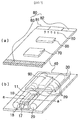
- Fig. 1 is a view illustrating a laser generating apparatus of the present invention.
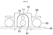
- Fig. 2 is a sectional view taken along line a-a' of Fig. 1b.
- Figs. 1a and 1b are views showing a laser generating apparatus embodied on a single PCB.
- the laser generating apparatus includes, on an upper surface of a PCB 40, a display unit 50, a switch unit 60, a control unit 70 and a safety unit 80.
- the display unit 50, the switch unit 60 and the control unit 70 are successively arranged from a first end of the front surface of the PCB 40 to a second end thereof.
- the display unit 50 displays a charge state of a battery and a level of laser intensity.
- the switch unit 60 includes a power on/off button, laser-intensity-level selection buttons and a laser emission button.
- the control unit 70 controls a drive unit 90, a battery 30 and the display unit 50 based on input signals of the switch unit 60 and the safety unit 80.
- the safety unit 80 includes a first contact point part 81 and a second contact point part 82 which are respectively disposed on left and right sides of the front end of the PCB 40, and a third contact point part 83 which is provided on a rear end of the PCB 40.
- a reflector 10 As shown in Fig. 1b , a reflector 10, the drive unit 90, capacitors 20 and the battery 30 are provided on the rear surface of the PCB 40.
- An internal space of the reflector 10 includes a first space 17 and a second space 18.
- a xenon tube 12 is mounted to the PCB 40 in the first space 17 and emits light.
- a crystal rod 11 is provided in the second space 18. The crystal rod 11 focuses light emitted from the xenon tube 12. Light focused by the crystal rod 11 is amplified, thus making an Er:YAG laser having a wavelength of 2940 nm.
- the drive unit 90 is disposed at a predetermined position behind the reflector 10.
- the capacitors 20 are disposed on opposite sides of the reflector 10 and the drive unit 90. Preferably, two to four capacitors 20 are provided.
- the battery 30 is disposed over both the drive unit 90 and the capacitors 20 that are provided on the opposite sides of the drive unit 90.
- the capacitors 20 are charged by the drive unit 90 that receives power from the battery 30.
- the charged capacitors 20 apply voltage to the xenon tube 12 so that the xenon tube 12 emits light.
- the emitted light is focused by the crystal rod 11, thus generating a laser beam.
- the crystal rod 11 and the xenon tube 12 which are disposed in the reflector 10 are oriented perpendicular to the surface of the PCB.
- Figs. 3 and 4 are respectively a perspective view and a sectional view illustrating the reflector of the laser generating apparatus according to the first embodiment the present invention.
- the xenon tube 12 is mounted to the PCB 40 and disposed in the first space 17 which is defined in a lower portion of the reflector 10.
- the crystal rod 11 is inserted into an insert hole 16 in the second space 17 which is defined in an upper portion of the reflector 10.
- the reflector 10 is mounted to the PCB 40 by bolts or by means of snap coupling designated by reference numeral 300.
- the laser generated from the crystal rod 11 is focused to a focusing lens 15 which is installed in a focusing lens installation part 13 and then is emitted through the opening 14.
- the laser emitted through the opening 14 penetrates the skin of a human body to enable to collect blood.
- the crystal rod 11, the focusing lens 15 and the opening 14 are coaxially arranged.
- An inner surface of the reflector 10 is plated with chrome, as designated by numeral 19, so that light of the xenon tube 12 can be reflected by the inner surface of the reflector 10.
- the surface of the PCB 40 to which the xenon tube 12 is mounted is plated with gold, as designated by numeral 41, so as to increase reflexibility of light emitted from the xenon tube 12.
- the reflector 10 has a curved shape having a predetermined radius of curvature or an aspherical surface shape so that light emitted from the xenon tube 12 can be effectively focused to the crystal rod 11.
- the reflector 10 can have any shape so long as it can increase the reflexibility.
- the reflector 10 may be formed into an integrated structure, a one-side open structure or a both-sides open structure, as long as the components can be easily installed in the reflector 10 or easily replaced with new ones.
- Fig. 5 is a block diagram showing the laser generating apparatus according to the present invention.
- control unit 70 of the laser generating apparatus controls the safety unit 80, the switch unit 60 and the display unit 50.
- the control unit 70 controls the apparatus such that when power is turned on, the battery 30 applies power to the drive unit 90.
- the drive unit 90 that has received power charges the capacitors 20.
- control unit 70 controls the display unit 50 such that the intensity of laser and the charge state of the capacitors 20 are displayed on the display unit 50.
- the control unit 70 controls the general operation of the laser generating apparatus in such a way that whether parts of the human body makes contact with the first through third contact point parts 81, 82 and 83 of the safety unit 80 is verified, and if there is nothing wrong, the laser emission button of the switch unit 60 is operated to emit a laser.
- Fig. 6 is a view showing an upper casing of the laser generating apparatus according to the present invention. A lower casing is omitted.
- the display unit 50 which displays the charge state and the level of laser output is provided at a predetermined position on the upper surface of a casing 200.
- the display unit 50 is embodied by any one selected from among LEDs, an LCD and an OLED.
- a first contact part 81' and a second contact part 82' are provided on left and right sides of a front end of the casing 200.
- a third contact part 83' is provided on a rear end of the casing 200.
- the first through third contact parts 81', 82' and 83' respectively make contact with the first through third contact point parts 81, 82 and 83.
- a power or cancel button 61 which makes contact with the switch unit 60 of Fig. 1a and is used to operate the laser generating apparatus or cancel the operation command
- left/right section buttons 62 which are used to adjust the intensity of laser
- a laser emission button 63 which is used for blood collecting.
- the laser generating apparatus of the present invention is used in such a way that the user makes contact with the third contact part 83' and brings the first and second contact parts 81' and 82' into contact with a part of the body to be involved with blood collection. Thereafter, the user pushes the laser emission button 63 to emit a laser. If even any one among the first through third contact parts 81' 82' and 83' does not make contact with the body part, a laser is not emitted.
- the laser generating apparatus When conducting the blood collection, to sense current that flows through the body of the user, one hand of the user makes contact with the third contact part 83', and the first and second contact parts 81' and 82' must be brought into contact with a portion of the body to be involved with the blood collection. Only in this case can the laser generating apparatus be operated.
- the laser generating apparatus when it is desired for the user to collect blood of a person, one hand of the user makes contact with the third contact part 83', and the other hand makes contact with a body part (the skin), for example a finger, of the target person before the first and second contact parts 81' and 82' are brought into contact with a blood collection involved portion of the target person. Only in this state can the laser generating apparatus be operated.
- the laser generating apparatus of the present invention can ensure safety and be prevented from being used wrongly.
- Figs. 7a and 7b are views respectively showing a front surface and a rear surface of the casing of the laser generating apparatus according to the first embodiment of the present invention.
- the first contact part 81' and the second contact part 82' are provided on left and right sides of the opening 14 in the front surface of the casing 200.
- a charging jack connector 100 which is used when the battery 30 is charged, is provided in the rear surface of the casing 200.
- the charging jack connector 100 is embodied by a charging terminal which can be connected to a TTA (standard 34 pins, 20 pins or 5 pins) or USB type charger or the like.
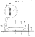
- Fig. 8 is a view showing a rear surface of a PCB of a laser generating apparatus according to a second embodiment of the present invention.
- the xenon tube 12 and the crystal rod 11 are horizontally provided in the first space 17 and the second space of the reflector 10a.
- the xenon tube 12 is connected to the PCB 40.
- the second embodiment of the present invention is advantageous in that the thickness thereof can be reduced compared to the case of the first embodiment, and the area of a gold-plated portion of the PCB 40 on which the xenon tube 12 is mounted is comparatively large so that a large quantity of light can be reflected.
- Fig. 9 is a flowchart showing a method of generating laser according to the present invention.
- the laser generating apparatus is turned on.
- the capacitors 20 are charged by the drive unit 90, at step S11.
- the level of laser intensity is selected to adjust the intensity of laser, at step S12.
- the charge state of the capacitor 20 is checked by means of the display unit 50. If the charging is completed, the first through third contact parts 81', 82' and 83' of the safety unit 80 are brought into contact with body parts of the user so that current can flow between the apparatus and the body, at step S14. Thereafter, at step S15, the laser emission button 63 is pressed to emit a laser. If a laser is not emitted or it is required to re-emit a laser, the charge state of the capacitors 20 is checked, and when the charging is completed, a laser is re-emitted, at step S16.
- making current flow may be achieved by bringing one hand of the user into contact with the third contact part 83' and bringing the first and second contact parts 81' and 82' of the safety unit 80 into contact with a target portion of the body part such as the skin, a finger, etc. to be involved with blood collection.
- making current flow may be achieved by bringing one hand of the user into contact with the third contact part 83', bringing the other hand of the user into contact with the body of a target person, and then bringing the first and second contact parts 81' and 82' of the safety unit 80 into contact with a target portion of the body part such as the skin, a finger, etc. of the target person.
- an Er:YAG laser having a wavelength of 2940 nm is used so that it is almost harmless to the human body. Furthermore, the present invention makes it possible for patients who suffer from diabetes to overcome the pain and fear of lancing the body with a needle to collect blood several times (three or more times) a day. Moreover, the present invention can solve a problem of secondary infection which may be caused when a needle is replaced with a new one or a needle that has been used for a patient is reused for another patient.
- the output of a laser can be controlled by adjusting the level of the laser intensity so that excessive bleeding can be prevented.
- the laser generating apparatus can be used not only for diabetic patients but also for collecting a blood sample for a blood test.
- the apparatus can collect only an appropriate amount of blood required for the blood test.
- the temperature of laser is very high, for example, is 1000°C or more, sterilizing effect can be provided so that a lanced portion can be prevented from being infected by bacteria.
Landscapes
- Health & Medical Sciences (AREA)
- Life Sciences & Earth Sciences (AREA)
- Physics & Mathematics (AREA)
- Engineering & Computer Science (AREA)
- Heart & Thoracic Surgery (AREA)
- Surgery (AREA)
- Biophysics (AREA)
- Pathology (AREA)
- Veterinary Medicine (AREA)
- Biomedical Technology (AREA)
- Public Health (AREA)
- Medical Informatics (AREA)
- Molecular Biology (AREA)
- Hematology (AREA)
- Animal Behavior & Ethology (AREA)
- General Health & Medical Sciences (AREA)
- Optics & Photonics (AREA)
- Electromagnetism (AREA)
- Dermatology (AREA)
- Plasma & Fusion (AREA)
- Radiation-Therapy Devices (AREA)
- Laser Surgery Devices (AREA)
- Lasers (AREA)
Description
- The present invention relates, in general, to apparatuses for generating lasers and, more particularly, to a laser generating apparatus and method which generates an Er:YAG laser to be used in blood collection.
- Generally, blood collection devices are used to collect blood from human bodies, for example, a blood sample used for a blood test. Particularly, diabetic patients mainly use such blood collection devices. Most diabetic patients use lancing devices for blood collection. Lancing devices are used in such a way as to lance the skin of with a sharp needle and cut capillary vessels. Disadvantages of such lancing devices for blood collection are as follows: the skin of the patient must be lanced and a callus is thus formed at the lanced portion; as a callus is formed, a depth to which the needle enters the skin of the patient must be gradually increased; and it is required to replace the needle with a new one every time. Particularly, a bigger problem is that if the needle is reused without replacement, there is the probability of a secondary injection being caused. Furthermore, because a needle is used for blood collection, patients suffer from pain and fear of the needle.
- In an effort to overcome the above disadvantages and affection risk, a laser blood collection device was proposed. However, although the laser blood collection device can solve problems in sanitation and overcome a disadvantage of a patient suffering from pain, there is a problem in that due to structural characteristics, the size thereof is increased, making it difficult to carry.
- Moreover, a laser generating apparatus is configured such that laser is emitted only by pushing an emission button. If children touch the laser blood collection device, a dangerous situation may be induced. Therefore, particular attention is required.
- Accordingly, the present invention has been made keeping in mind the above problems occurring in the prior art, and an object of the present invention is to provide an apparatus and method for generating a laser which is able to solve the conventional sanitation problem and reduce pain during blood collection.
- Another object of the present invention is to provide an apparatus and method for generating a laser which is reduced in size to increase the portability thereof and is able to resist water.
- A further object of the present invention is to provide an apparatus and method for generating a laser which includes an accident prevention structure, thus markedly enhancing safety.
- In order to accomplish the above objects, in an aspect, the present invention provides a apparatus according to claim 1.
- The xenon tube and the crystal rod may be provided in the reflector and oriented perpendicular to or parallel to the rear surface of the PCB.
- An inner surface of the reflector may be plated with chrome.
- The PCB in contact with an inner surface of the reflector may be plated with gold.
- The display unit may be embodied by at least one selected from among an LED, an LCD and an OLED.
- The first through third contact point parts of the safety unit may respectively make contact with first through third contact parts of a casing.
- The switch unit may include: a power button used to turn on or off the laser generating apparatus; a selection button used to select a level of laser intensity; and a laser emission button used to conduct blood collection.
- Blood collection may be conducted in such a way that one hand of a user makes contact with the third contact part, and the first and second contact parts are brought into contact with a target portion of a body (skin) of the user.
- Blood collection may be conducted in such a way that one hand of a user makes contact with the third contact part, the other hand of the user makes contact with a body of a patient (another person), and the first and second contact parts are brought into contact with a target portion of the body of the patient.
- The apparatus may further include, on a rear surface of the casing, a charging jack connector used to charge the battery.
- The present application describes a method for generating a laser, including turning on power; charging a capacitor using a drive unit; selecting a level of laser emission and adjusting an intensity of a laser; checking a charge state of the capacitor using a display unit; after charging of the capacitor is completed, bringing a safety unit into contact with a human body to form an electrified state; and emitting a laser when in the electrified state.
- The bringing the safety unit into contact with the human body may include: bringing one hand of a user into contact with a third contact part of the safety unit; and bringing first and second contact parts of the safety unit into contact with a target portion of a body (skin) of the user.
- The bringing the safety unit into contact with the body part may include: bringing one hand of a user into contact with a third contact part of the safety unit; bringing the other hand of the user into contact with a body of a patient (another person); and bringing first and second contact parts of the safety unit into contact with a target portion (finger) of the patient.
- A laser generating apparatus according to the present invention is configured such that an Er:YAG laser which has a wavelength of 2940 nm and is widely used in the areas of dermatology and dentistry is used and the intensity of laser can be adjusted. Therefore, excessive bleeding can be prevented during blood collection.
- Furthermore, the present invention has a reduced size to facilitate carrying and has a safety unit which is operated in such a way as to sense contact between the apparatus and a human body, thus improving the safety for the user and preventing accidents.
-
-
Figs. 1a and 1b show a front surface and a rear surface of a PCB of a laser generating apparatus according to a first embodiment of the present invention; -
Fig. 2 is a sectional view taken along line a-a' ofFig. 1b . -
Fig. 3 is a perspective view of a reflector according to the present invention; -
Fig. 4 is a sectional view of the reflector according to the present invention; -
Fig. 5 is a block diagram showing the laser generating apparatus according to the present invention; -
Fig. 6 is a view showing an upper surface of a casing of the laser generating apparatus according to the present invention; -
Fig. 7 is a view showing a front surface of the casing of the laser generating apparatus according to the present invention; -
Fig. 8 is a view showing a rear surface of a PCB of a laser generating apparatus according to a second embodiment of the present invention; -
Fig. 9 is a flowchart showing a method of generating laser according to the present invention. - Hereinafter, a first embodiment of the present invention will be described in detail with reference to the attached drawings.
-
Fig. 1 is a view illustrating a laser generating apparatus of the present invention.Fig. 2 is a sectional view taken along line a-a' ofFig. 1b. Figs. 1a and 1b are views showing a laser generating apparatus embodied on a single PCB. - As shown in
Fig. 1a , the laser generating apparatus according to the present invention includes, on an upper surface of aPCB 40, adisplay unit 50, aswitch unit 60, acontrol unit 70 and asafety unit 80. - The
display unit 50, theswitch unit 60 and thecontrol unit 70 are successively arranged from a first end of the front surface of thePCB 40 to a second end thereof. - The
display unit 50 displays a charge state of a battery and a level of laser intensity. - The
switch unit 60 includes a power on/off button, laser-intensity-level selection buttons and a laser emission button. - The
control unit 70 controls adrive unit 90, abattery 30 and thedisplay unit 50 based on input signals of theswitch unit 60 and thesafety unit 80. - The
safety unit 80 includes a firstcontact point part 81 and a secondcontact point part 82 which are respectively disposed on left and right sides of the front end of thePCB 40, and a thirdcontact point part 83 which is provided on a rear end of thePCB 40. - As shown in
Fig. 1b , areflector 10, thedrive unit 90,capacitors 20 and thebattery 30 are provided on the rear surface of thePCB 40. - An internal space of the
reflector 10 includes afirst space 17 and asecond space 18. Axenon tube 12 is mounted to thePCB 40 in thefirst space 17 and emits light. Acrystal rod 11 is provided in thesecond space 18. Thecrystal rod 11 focuses light emitted from thexenon tube 12. Light focused by thecrystal rod 11 is amplified, thus making an Er:YAG laser having a wavelength of 2940 nm. - The
drive unit 90 is disposed at a predetermined position behind thereflector 10. Thecapacitors 20 are disposed on opposite sides of thereflector 10 and thedrive unit 90. Preferably, two to fourcapacitors 20 are provided. Thebattery 30 is disposed over both thedrive unit 90 and thecapacitors 20 that are provided on the opposite sides of thedrive unit 90. - The
capacitors 20 are charged by thedrive unit 90 that receives power from thebattery 30. The chargedcapacitors 20 apply voltage to thexenon tube 12 so that thexenon tube 12 emits light. The emitted light is focused by thecrystal rod 11, thus generating a laser beam. - The
crystal rod 11 and thexenon tube 12 which are disposed in thereflector 10 are oriented perpendicular to the surface of the PCB. -
Figs. 3 and4 are respectively a perspective view and a sectional view illustrating the reflector of the laser generating apparatus according to the first embodiment the present invention. - As shown in
Figs. 3 and4 , thexenon tube 12 is mounted to thePCB 40 and disposed in thefirst space 17 which is defined in a lower portion of thereflector 10. Thecrystal rod 11 is inserted into aninsert hole 16 in thesecond space 17 which is defined in an upper portion of thereflector 10. Thereflector 10 is mounted to thePCB 40 by bolts or by means of snap coupling designated byreference numeral 300. - The laser generated from the
crystal rod 11 is focused to a focusinglens 15 which is installed in a focusinglens installation part 13 and then is emitted through theopening 14. The laser emitted through theopening 14 penetrates the skin of a human body to enable to collect blood. Thecrystal rod 11, the focusinglens 15 and theopening 14 are coaxially arranged. - An inner surface of the
reflector 10 is plated with chrome, as designated bynumeral 19, so that light of thexenon tube 12 can be reflected by the inner surface of thereflector 10. The surface of thePCB 40 to which thexenon tube 12 is mounted is plated with gold, as designated bynumeral 41, so as to increase reflexibility of light emitted from thexenon tube 12. - Preferably, the
reflector 10 has a curved shape having a predetermined radius of curvature or an aspherical surface shape so that light emitted from thexenon tube 12 can be effectively focused to thecrystal rod 11. Thereflector 10 can have any shape so long as it can increase the reflexibility. Furthermore, thereflector 10 may be formed into an integrated structure, a one-side open structure or a both-sides open structure, as long as the components can be easily installed in thereflector 10 or easily replaced with new ones. -
Fig. 5 is a block diagram showing the laser generating apparatus according to the present invention. - As shown in
Fig. 5 , thecontrol unit 70 of the laser generating apparatus according to the present invention controls thesafety unit 80, theswitch unit 60 and thedisplay unit 50. - The
control unit 70 controls the apparatus such that when power is turned on, thebattery 30 applies power to thedrive unit 90. Thedrive unit 90 that has received power charges thecapacitors 20. - Furthermore, when the intensity of laser is adjusted by the
switch unit 60, thecontrol unit 70 controls thedisplay unit 50 such that the intensity of laser and the charge state of thecapacitors 20 are displayed on thedisplay unit 50. - After the charging of the
capacitor 20 has been completed and the adjustment in the intensity of laser using theswitch unit 60 has been completed, thecontrol unit 70 controls the general operation of the laser generating apparatus in such a way that whether parts of the human body makes contact with the first through thirdcontact point parts safety unit 80 is verified, and if there is nothing wrong, the laser emission button of theswitch unit 60 is operated to emit a laser. -
Fig. 6 is a view showing an upper casing of the laser generating apparatus according to the present invention. A lower casing is omitted. - As shown in
Fig. 6 , thedisplay unit 50 which displays the charge state and the level of laser output is provided at a predetermined position on the upper surface of acasing 200. Thedisplay unit 50 is embodied by any one selected from among LEDs, an LCD and an OLED. - A first contact part 81' and a second contact part 82' are provided on left and right sides of a front end of the
casing 200. A third contact part 83' is provided on a rear end of thecasing 200. The first through third contact parts 81', 82' and 83' respectively make contact with the first through thirdcontact point parts - Furthermore, provided are a power or cancel
button 61 which makes contact with theswitch unit 60 ofFig. 1a and is used to operate the laser generating apparatus or cancel the operation command, left/right section buttons 62 which are used to adjust the intensity of laser, and alaser emission button 63 which is used for blood collecting. - The laser generating apparatus of the present invention is used in such a way that the user makes contact with the third contact part 83' and brings the first and second contact parts 81' and 82' into contact with a part of the body to be involved with blood collection. Thereafter, the user pushes the
laser emission button 63 to emit a laser. If even any one among the first through third contact parts 81' 82' and 83' does not make contact with the body part, a laser is not emitted. - When conducting the blood collection, to sense current that flows through the body of the user, one hand of the user makes contact with the third contact part 83', and the first and second contact parts 81' and 82' must be brought into contact with a portion of the body to be involved with the blood collection. Only in this case can the laser generating apparatus be operated.
- Meanwhile, when it is desired for the user to collect blood of a person, one hand of the user makes contact with the third contact part 83', and the other hand makes contact with a body part (the skin), for example a finger, of the target person before the first and second contact parts 81' and 82' are brought into contact with a blood collection involved portion of the target person. Only in this state can the laser generating apparatus be operated.
- Therefore, the laser generating apparatus of the present invention can ensure safety and be prevented from being used wrongly.
-
Figs. 7a and 7b are views respectively showing a front surface and a rear surface of the casing of the laser generating apparatus according to the first embodiment of the present invention. - As shown in
Figs. 7a and 7b , the first contact part 81' and the second contact part 82' are provided on left and right sides of theopening 14 in the front surface of thecasing 200. A charging jack connector 100, which is used when thebattery 30 is charged, is provided in the rear surface of thecasing 200. The charging jack connector 100 is embodied by a charging terminal which can be connected to a TTA (standard 34 pins, 20 pins or 5 pins) or USB type charger or the like. - Hereinafter, a second embodiment of the present invention will be described in detail with reference to the attached drawings.
-
Fig. 8 is a view showing a rear surface of a PCB of a laser generating apparatus according to a second embodiment of the present invention. - As shown in
Fig. 8 , although the general construction of the rear surface of the PCB according to the second embodiment of the present invention is the same as that of the first embodiment shown inFig. 1b , only the shape of thereflector 10a is different between the first embodiment and the second embodiment. - In this embodiment, the
xenon tube 12 and thecrystal rod 11 are horizontally provided in thefirst space 17 and the second space of thereflector 10a. Thexenon tube 12 is connected to thePCB 40. - The second embodiment of the present invention is advantageous in that the thickness thereof can be reduced compared to the case of the first embodiment, and the area of a gold-plated portion of the
PCB 40 on which thexenon tube 12 is mounted is comparatively large so that a large quantity of light can be reflected. -
Fig. 9 is a flowchart showing a method of generating laser according to the present invention. - As shown in
Fig. 9 , in the laser generating method, at step S10, the laser generating apparatus is turned on. When the power is turned on, thecapacitors 20 are charged by thedrive unit 90, at step S11. While thecapacitors 20 are being charged, the level of laser intensity is selected to adjust the intensity of laser, at step S12. - At step S13, the charge state of the
capacitor 20 is checked by means of thedisplay unit 50. If the charging is completed, the first through third contact parts 81', 82' and 83' of thesafety unit 80 are brought into contact with body parts of the user so that current can flow between the apparatus and the body, at step S14. Thereafter, at step S15, thelaser emission button 63 is pressed to emit a laser. If a laser is not emitted or it is required to re-emit a laser, the charge state of thecapacitors 20 is checked, and when the charging is completed, a laser is re-emitted, at step S16. - Here, making current flow may be achieved by bringing one hand of the user into contact with the third contact part 83' and bringing the first and second contact parts 81' and 82' of the
safety unit 80 into contact with a target portion of the body part such as the skin, a finger, etc. to be involved with blood collection. - Alternatively, making current flow may be achieved by bringing one hand of the user into contact with the third contact part 83', bringing the other hand of the user into contact with the body of a target person, and then bringing the first and second contact parts 81' and 82' of the
safety unit 80 into contact with a target portion of the body part such as the skin, a finger, etc. of the target person. - As described above, in a laser generating apparatus according to the present invention, an Er:YAG laser having a wavelength of 2940 nm is used so that it is almost harmless to the human body. Furthermore, the present invention makes it possible for patients who suffer from diabetes to overcome the pain and fear of lancing the body with a needle to collect blood several times (three or more times) a day. Moreover, the present invention can solve a problem of secondary infection which may be caused when a needle is replaced with a new one or a needle that has been used for a patient is reused for another patient. The output of a laser can be controlled by adjusting the level of the laser intensity so that excessive bleeding can be prevented.
- In addition, the laser generating apparatus can be used not only for diabetic patients but also for collecting a blood sample for a blood test. The apparatus can collect only an appropriate amount of blood required for the blood test. Furthermore, because the temperature of laser is very high, for example, is 1000°C or more, sterilizing effect can be provided so that a lanced portion can be prevented from being infected by bacteria.
Claims (10)
- An apparatus for generating a laser, comprising:a display unit (50) displaying a battery charge state and an intensity of a laser; a switch unit (60) provided to turn power on/off, adjust the intensity of the laser and control emission of the laser; and a control unit (70) controlling at least the display unit (50), anda reflector (10, 10a) having a first space (17) and a second space (18) therein; a xenon tube (12) emitting light in the first space (17); a crystal rod (11) amplifying the light in the second space (18) and generating a laser; a focusing lens (15) focusing the laser and forming a focus; a focusing lens installation part (13) in which the focusing lens (15) is installed; a capacitor (20) applying voltage to the xenon tube (12); a drive unit (90) controlled by the control unit (70) and charging the capacitor; and a battery (30) supplying power to the drive unit (90),Characterized in that the apparatus further comprises:a safety unit (80) comprising first through third contact point parts (81, 82, 83), the first and second contact point parts (81,82) being disposed on left and right sides of a front end of the PCB (40) and the third contact point part (83) being provided on a rear end of the PCB (40),and in that the control unit (70) controls an operation of the apparatus when:* a user makes contact with his hand with the third contact point part, and* a body part of a user to be involved with blood collection makes further contact with said first and second contact point parts, andthe display unit (50), the switch unit (60), the safety unit (80), the control unit (70) are arranged on an upper surface of a PCB and the reflector (10, 10a), the xenon tube (12), the crystal rod (11), the focusing lens (15), the focusing lens installation part (13), the capacitor (20), the drive unit (90), and the battery (30) are arranged on a rear surface of the PCB.
- The apparatus according to claim 1, wherein the xenon tube (12) and the crystal rod (11) are provided in the reflector (10, 10a) and oriented perpendicular to or parallel to the rear surface of the PCB (40).
- The apparatus according to claim 1, wherein an inner surface of the reflector (10, 10a) is plated with chrome.
- The apparatus according to claim 1, wherein the PCB (40) in contact with an inner surface of the reflector (10, 10a) is plated with gold.
- The apparatus according to claim 1, wherein the display unit (50) is embodied by at least one selected from among an LED, an LCD and an OLED.
- The apparatus according to claim 1, wherein the first through third contact point parts (81, 82, 83) of the safety unit (80) respectively make contact with first through third contact parts (81', 82', 83') of a casing (200).
- The apparatus according to claim 1, wherein the switch unit (60) comprises a power button used to turn on or off the apparatus, a selection button used to select a level of laser intensity and a laser emission button used to conduct blood collection.
- The apparatus according to claim 6, wherein the third contact part (83') of the casing (200) is in contact with one hand of a user, and the first and second contact parts (81', 82') of the casing (200) are brought into contact with a target portion of a body of the user.
- The apparatus according to claim 6, wherein the third contact part (83') of the casing (200) is in contact with one hand of a user and the first and second contact parts (81', 82') of the casing (200) are brought into contact with a target portion of the body of another person contacting with the other hand of the user.
- The apparatus according to claim 6, further comprising, on a rear surface of the casing, a charging jack connector (100) used to charge the battery (30).
Applications Claiming Priority (2)
| Application Number | Priority Date | Filing Date | Title |
|---|---|---|---|
| KR1020110021622A KR101185482B1 (en) | 2011-03-11 | 2011-03-11 | Laser apparatus and laser production method |
| PCT/KR2012/001720 WO2012124936A2 (en) | 2011-03-11 | 2012-03-09 | Method and apparatus for generating laser |
Publications (3)
| Publication Number | Publication Date |
|---|---|
| EP2684520A2 EP2684520A2 (en) | 2014-01-15 |
| EP2684520A4 EP2684520A4 (en) | 2014-09-03 |
| EP2684520B1 true EP2684520B1 (en) | 2016-03-09 |
Family
ID=46831177
Family Applications (1)
| Application Number | Title | Priority Date | Filing Date |
|---|---|---|---|
| EP12756992.9A Not-in-force EP2684520B1 (en) | 2011-03-11 | 2012-03-09 | Apparatus for generating laser |
Country Status (6)
| Country | Link |
|---|---|
| US (1) | US9325147B2 (en) |
| EP (1) | EP2684520B1 (en) |
| KR (1) | KR101185482B1 (en) |
| CN (1) | CN103732141B (en) |
| CA (1) | CA2831696A1 (en) |
| WO (1) | WO2012124936A2 (en) |
Families Citing this family (3)
| Publication number | Priority date | Publication date | Assignee | Title |
|---|---|---|---|---|
| CN108201443B (en) * | 2016-12-19 | 2021-08-10 | 比亚迪股份有限公司 | Laser blood sampling instrument |
| KR102371000B1 (en) * | 2021-03-02 | 2022-03-07 | (주)스핀텍 | High power laser light source |
| CN113795087B (en) * | 2021-11-15 | 2022-05-03 | 深圳市大族数控科技股份有限公司 | Windowing method and windowing equipment |
Family Cites Families (13)
| Publication number | Priority date | Publication date | Assignee | Title |
|---|---|---|---|---|
| US5643252A (en) * | 1992-10-28 | 1997-07-01 | Venisect, Inc. | Laser perforator |
| US5947957A (en) * | 1994-12-23 | 1999-09-07 | Jmar Technology Co. | Portable laser for blood sampling |
| US6074383A (en) * | 1998-09-30 | 2000-06-13 | Becton Dickinson And Company | Laser lancet tip |
| US6733493B2 (en) | 2000-11-16 | 2004-05-11 | Innotech Usa, Inc. | Laser skin perforator |
| JPWO2007108518A1 (en) * | 2006-03-22 | 2009-08-06 | パナソニック株式会社 | Blood test apparatus and control method thereof |
| EP1997433B1 (en) * | 2006-03-22 | 2013-05-15 | Panasonic Corporation | Laser perforation device and laser perforation method |
| KR100782142B1 (en) | 2006-04-14 | 2007-12-04 | (주)아이소텍 | Er: very low bloodless blood collection device using BA laser and blood glucose measurement device using it |
| US7577179B2 (en) * | 2006-09-12 | 2009-08-18 | Panasonic Corporation | Laser irradiation apparatus |
| JP2008194345A (en) * | 2007-02-15 | 2008-08-28 | Matsushita Electric Ind Co Ltd | Laser puncturing apparatus and laser puncturing method |
| KR20100032364A (en) * | 2007-04-29 | 2010-03-25 | 아크레이 가부시키가이샤 | Analysis device |
| WO2009031312A1 (en) * | 2007-09-04 | 2009-03-12 | Panasonic Corporation | Blood testing device |
| WO2009031313A1 (en) * | 2007-09-04 | 2009-03-12 | Panasonic Corporation | Blood analysis device and blood analysis system using the same |
| JP2010099107A (en) | 2008-10-21 | 2010-05-06 | Panasonic Corp | Blood testing device |
-
2011
- 2011-03-11 KR KR1020110021622A patent/KR101185482B1/en not_active Expired - Fee Related
-
2012
- 2012-03-09 EP EP12756992.9A patent/EP2684520B1/en not_active Not-in-force
- 2012-03-09 US US14/004,526 patent/US9325147B2/en not_active Expired - Fee Related
- 2012-03-09 CN CN201280022796.XA patent/CN103732141B/en not_active Expired - Fee Related
- 2012-03-09 CA CA2831696A patent/CA2831696A1/en not_active Abandoned
- 2012-03-09 WO PCT/KR2012/001720 patent/WO2012124936A2/en not_active Ceased
Also Published As
| Publication number | Publication date |
|---|---|
| CN103732141B (en) | 2016-11-02 |
| EP2684520A2 (en) | 2014-01-15 |
| KR101185482B1 (en) | 2012-10-02 |
| WO2012124936A2 (en) | 2012-09-20 |
| US9325147B2 (en) | 2016-04-26 |
| CA2831696A1 (en) | 2012-09-20 |
| CN103732141A (en) | 2014-04-16 |
| KR20120103793A (en) | 2012-09-20 |
| WO2012124936A3 (en) | 2012-12-20 |
| US20140081171A1 (en) | 2014-03-20 |
| EP2684520A4 (en) | 2014-09-03 |
Similar Documents
| Publication | Publication Date | Title |
|---|---|---|
| KR100782142B1 (en) | Er: very low bloodless blood collection device using BA laser and blood glucose measurement device using it | |
| US10758118B2 (en) | Handheld ophthalmic laser system with replaceable contact tips and treatment guide | |
| RU2309699C2 (en) | Skin laser perforator | |
| US20070255180A1 (en) | Lancing device cap with integrated light source | |
| US20080140164A1 (en) | Light emitting therapeutic devices and methods | |
| KR101058681B1 (en) | Laser drilling device and laser drilling method | |
| ES2818182T3 (en) | Laser irradiation device | |
| SG191947A1 (en) | Laser therapy appratus, laser therapy system, and determination method | |
| CN103561650B (en) | Portable laser blood sampling device with double safety device and disposable cap for use therewith | |
| US9325147B2 (en) | Method and apparatus for generating laser | |
| KR101471884B1 (en) | Portable handpiece treatment apparatus using laser | |
| EP2394700A1 (en) | Device for irradiating tissue | |
| JP2005279053A (en) | Pupil response confirmation device and fatigue recovery facilitating device | |
| KR101775631B1 (en) | Lancing device and control method thereof | |
| EP3246069A1 (en) | Improved medical device for laser therapy | |
| JP4340250B2 (en) | Phototherapy device | |
| CN202437329U (en) | Manipulative radiofrequency catheter electrode device | |
| KR20140120952A (en) | Diode Laser Using Blood Sampling Device | |
| JP2010104491A (en) | Puncture device and blood test instrument using the same | |
| JP5011935B2 (en) | Blood test equipment | |
| JPH11151307A (en) | Laser therapy equipment | |
| KR200420950Y1 (en) | Er: very low bloodless blood collection device using BA laser and blood glucose measurement device using it | |
| KR101650127B1 (en) | Perforation device | |
| JP2008000557A (en) | Medical infusion tube illuminating device | |
| JP5922682B2 (en) | Hair removal treatment equipment |
Legal Events
| Date | Code | Title | Description |
|---|---|---|---|
| PUAI | Public reference made under article 153(3) epc to a published international application that has entered the european phase |
Free format text: ORIGINAL CODE: 0009012 |
|
| 17P | Request for examination filed |
Effective date: 20131011 |
|
| AK | Designated contracting states |
Kind code of ref document: A2 Designated state(s): AL AT BE BG CH CY CZ DE DK EE ES FI FR GB GR HR HU IE IS IT LI LT LU LV MC MK MT NL NO PL PT RO RS SE SI SK SM TR |
|
| DAX | Request for extension of the european patent (deleted) | ||
| A4 | Supplementary search report drawn up and despatched |
Effective date: 20140801 |
|
| RIC1 | Information provided on ipc code assigned before grant |
Ipc: H01S 3/10 20060101ALI20140728BHEP Ipc: A61B 18/20 20060101ALI20140728BHEP Ipc: A61B 5/151 20060101ALI20140728BHEP Ipc: A61B 5/15 20060101AFI20140728BHEP |
|
| 17Q | First examination report despatched |
Effective date: 20150316 |
|
| GRAP | Despatch of communication of intention to grant a patent |
Free format text: ORIGINAL CODE: EPIDOSNIGR1 |
|
| INTG | Intention to grant announced |
Effective date: 20150910 |
|
| GRAS | Grant fee paid |
Free format text: ORIGINAL CODE: EPIDOSNIGR3 |
|
| GRAA | (expected) grant |
Free format text: ORIGINAL CODE: 0009210 |
|
| AK | Designated contracting states |
Kind code of ref document: B1 Designated state(s): AL AT BE BG CH CY CZ DE DK EE ES FI FR GB GR HR HU IE IS IT LI LT LU LV MC MK MT NL NO PL PT RO RS SE SI SK SM TR |
|
| REG | Reference to a national code |
Ref country code: GB Ref legal event code: FG4D |
|
| REG | Reference to a national code |
Ref country code: AT Ref legal event code: REF Ref document number: 778876 Country of ref document: AT Kind code of ref document: T Effective date: 20160315 Ref country code: CH Ref legal event code: EP |
|
| REG | Reference to a national code |
Ref country code: IE Ref legal event code: FG4D |
|
| REG | Reference to a national code |
Ref country code: DE Ref legal event code: R096 Ref document number: 602012015409 Country of ref document: DE |
|
| REG | Reference to a national code |
Ref country code: LT Ref legal event code: MG4D |
|
| REG | Reference to a national code |
Ref country code: NL Ref legal event code: MP Effective date: 20160309 |
|
| PG25 | Lapsed in a contracting state [announced via postgrant information from national office to epo] |
Ref country code: FI Free format text: LAPSE BECAUSE OF FAILURE TO SUBMIT A TRANSLATION OF THE DESCRIPTION OR TO PAY THE FEE WITHIN THE PRESCRIBED TIME-LIMIT Effective date: 20160309 Ref country code: NO Free format text: LAPSE BECAUSE OF FAILURE TO SUBMIT A TRANSLATION OF THE DESCRIPTION OR TO PAY THE FEE WITHIN THE PRESCRIBED TIME-LIMIT Effective date: 20160609 Ref country code: ES Free format text: LAPSE BECAUSE OF FAILURE TO SUBMIT A TRANSLATION OF THE DESCRIPTION OR TO PAY THE FEE WITHIN THE PRESCRIBED TIME-LIMIT Effective date: 20160309 Ref country code: GR Free format text: LAPSE BECAUSE OF FAILURE TO SUBMIT A TRANSLATION OF THE DESCRIPTION OR TO PAY THE FEE WITHIN THE PRESCRIBED TIME-LIMIT Effective date: 20160610 Ref country code: HR Free format text: LAPSE BECAUSE OF FAILURE TO SUBMIT A TRANSLATION OF THE DESCRIPTION OR TO PAY THE FEE WITHIN THE PRESCRIBED TIME-LIMIT Effective date: 20160309 |
|
| REG | Reference to a national code |
Ref country code: AT Ref legal event code: MK05 Ref document number: 778876 Country of ref document: AT Kind code of ref document: T Effective date: 20160309 |
|
| PG25 | Lapsed in a contracting state [announced via postgrant information from national office to epo] |
Ref country code: LT Free format text: LAPSE BECAUSE OF FAILURE TO SUBMIT A TRANSLATION OF THE DESCRIPTION OR TO PAY THE FEE WITHIN THE PRESCRIBED TIME-LIMIT Effective date: 20160309 Ref country code: RS Free format text: LAPSE BECAUSE OF FAILURE TO SUBMIT A TRANSLATION OF THE DESCRIPTION OR TO PAY THE FEE WITHIN THE PRESCRIBED TIME-LIMIT Effective date: 20160309 Ref country code: PL Free format text: LAPSE BECAUSE OF FAILURE TO SUBMIT A TRANSLATION OF THE DESCRIPTION OR TO PAY THE FEE WITHIN THE PRESCRIBED TIME-LIMIT Effective date: 20160309 Ref country code: BE Free format text: LAPSE BECAUSE OF NON-PAYMENT OF DUE FEES Effective date: 20160331 Ref country code: LV Free format text: LAPSE BECAUSE OF FAILURE TO SUBMIT A TRANSLATION OF THE DESCRIPTION OR TO PAY THE FEE WITHIN THE PRESCRIBED TIME-LIMIT Effective date: 20160309 Ref country code: SE Free format text: LAPSE BECAUSE OF FAILURE TO SUBMIT A TRANSLATION OF THE DESCRIPTION OR TO PAY THE FEE WITHIN THE PRESCRIBED TIME-LIMIT Effective date: 20160309 Ref country code: NL Free format text: LAPSE BECAUSE OF FAILURE TO SUBMIT A TRANSLATION OF THE DESCRIPTION OR TO PAY THE FEE WITHIN THE PRESCRIBED TIME-LIMIT Effective date: 20160309 |
|
| PG25 | Lapsed in a contracting state [announced via postgrant information from national office to epo] |
Ref country code: IS Free format text: LAPSE BECAUSE OF FAILURE TO SUBMIT A TRANSLATION OF THE DESCRIPTION OR TO PAY THE FEE WITHIN THE PRESCRIBED TIME-LIMIT Effective date: 20160709 Ref country code: EE Free format text: LAPSE BECAUSE OF FAILURE TO SUBMIT A TRANSLATION OF THE DESCRIPTION OR TO PAY THE FEE WITHIN THE PRESCRIBED TIME-LIMIT Effective date: 20160309 |
|
| REG | Reference to a national code |
Ref country code: CH Ref legal event code: PL |
|
| PG25 | Lapsed in a contracting state [announced via postgrant information from national office to epo] |
Ref country code: PT Free format text: LAPSE BECAUSE OF FAILURE TO SUBMIT A TRANSLATION OF THE DESCRIPTION OR TO PAY THE FEE WITHIN THE PRESCRIBED TIME-LIMIT Effective date: 20160711 Ref country code: AT Free format text: LAPSE BECAUSE OF FAILURE TO SUBMIT A TRANSLATION OF THE DESCRIPTION OR TO PAY THE FEE WITHIN THE PRESCRIBED TIME-LIMIT Effective date: 20160309 Ref country code: RO Free format text: LAPSE BECAUSE OF FAILURE TO SUBMIT A TRANSLATION OF THE DESCRIPTION OR TO PAY THE FEE WITHIN THE PRESCRIBED TIME-LIMIT Effective date: 20160309 Ref country code: SK Free format text: LAPSE BECAUSE OF FAILURE TO SUBMIT A TRANSLATION OF THE DESCRIPTION OR TO PAY THE FEE WITHIN THE PRESCRIBED TIME-LIMIT Effective date: 20160309 Ref country code: CZ Free format text: LAPSE BECAUSE OF FAILURE TO SUBMIT A TRANSLATION OF THE DESCRIPTION OR TO PAY THE FEE WITHIN THE PRESCRIBED TIME-LIMIT Effective date: 20160309 Ref country code: SM Free format text: LAPSE BECAUSE OF FAILURE TO SUBMIT A TRANSLATION OF THE DESCRIPTION OR TO PAY THE FEE WITHIN THE PRESCRIBED TIME-LIMIT Effective date: 20160309 |
|
| REG | Reference to a national code |
Ref country code: DE Ref legal event code: R097 Ref document number: 602012015409 Country of ref document: DE |
|
| REG | Reference to a national code |
Ref country code: IE Ref legal event code: MM4A |
|
| PG25 | Lapsed in a contracting state [announced via postgrant information from national office to epo] |
Ref country code: IT Free format text: LAPSE BECAUSE OF FAILURE TO SUBMIT A TRANSLATION OF THE DESCRIPTION OR TO PAY THE FEE WITHIN THE PRESCRIBED TIME-LIMIT Effective date: 20160309 Ref country code: BE Free format text: LAPSE BECAUSE OF FAILURE TO SUBMIT A TRANSLATION OF THE DESCRIPTION OR TO PAY THE FEE WITHIN THE PRESCRIBED TIME-LIMIT Effective date: 20160309 |
|
| PLBE | No opposition filed within time limit |
Free format text: ORIGINAL CODE: 0009261 |
|
| STAA | Information on the status of an ep patent application or granted ep patent |
Free format text: STATUS: NO OPPOSITION FILED WITHIN TIME LIMIT |
|
| PG25 | Lapsed in a contracting state [announced via postgrant information from national office to epo] |
Ref country code: CH Free format text: LAPSE BECAUSE OF NON-PAYMENT OF DUE FEES Effective date: 20160331 Ref country code: DK Free format text: LAPSE BECAUSE OF FAILURE TO SUBMIT A TRANSLATION OF THE DESCRIPTION OR TO PAY THE FEE WITHIN THE PRESCRIBED TIME-LIMIT Effective date: 20160309 Ref country code: IE Free format text: LAPSE BECAUSE OF NON-PAYMENT OF DUE FEES Effective date: 20160309 Ref country code: LI Free format text: LAPSE BECAUSE OF NON-PAYMENT OF DUE FEES Effective date: 20160331 |
|
| 26N | No opposition filed |
Effective date: 20161212 |
|
| REG | Reference to a national code |
Ref country code: FR Ref legal event code: ST Effective date: 20170120 |
|
| PG25 | Lapsed in a contracting state [announced via postgrant information from national office to epo] |
Ref country code: BG Free format text: LAPSE BECAUSE OF FAILURE TO SUBMIT A TRANSLATION OF THE DESCRIPTION OR TO PAY THE FEE WITHIN THE PRESCRIBED TIME-LIMIT Effective date: 20160609 |
|
| GBPC | Gb: european patent ceased through non-payment of renewal fee |
Effective date: 20160609 |
|
| PG25 | Lapsed in a contracting state [announced via postgrant information from national office to epo] |
Ref country code: FR Free format text: LAPSE BECAUSE OF NON-PAYMENT OF DUE FEES Effective date: 20160509 |
|
| PG25 | Lapsed in a contracting state [announced via postgrant information from national office to epo] |
Ref country code: SI Free format text: LAPSE BECAUSE OF FAILURE TO SUBMIT A TRANSLATION OF THE DESCRIPTION OR TO PAY THE FEE WITHIN THE PRESCRIBED TIME-LIMIT Effective date: 20160309 Ref country code: GB Free format text: LAPSE BECAUSE OF NON-PAYMENT OF DUE FEES Effective date: 20160609 |
|
| PG25 | Lapsed in a contracting state [announced via postgrant information from national office to epo] |
Ref country code: MT Free format text: LAPSE BECAUSE OF FAILURE TO SUBMIT A TRANSLATION OF THE DESCRIPTION OR TO PAY THE FEE WITHIN THE PRESCRIBED TIME-LIMIT Effective date: 20160309 |
|
| PG25 | Lapsed in a contracting state [announced via postgrant information from national office to epo] |
Ref country code: MC Free format text: LAPSE BECAUSE OF FAILURE TO SUBMIT A TRANSLATION OF THE DESCRIPTION OR TO PAY THE FEE WITHIN THE PRESCRIBED TIME-LIMIT Effective date: 20160309 |
|
| PG25 | Lapsed in a contracting state [announced via postgrant information from national office to epo] |
Ref country code: HU Free format text: LAPSE BECAUSE OF FAILURE TO SUBMIT A TRANSLATION OF THE DESCRIPTION OR TO PAY THE FEE WITHIN THE PRESCRIBED TIME-LIMIT; INVALID AB INITIO Effective date: 20120309 Ref country code: CY Free format text: LAPSE BECAUSE OF FAILURE TO SUBMIT A TRANSLATION OF THE DESCRIPTION OR TO PAY THE FEE WITHIN THE PRESCRIBED TIME-LIMIT Effective date: 20160309 |
|
| PG25 | Lapsed in a contracting state [announced via postgrant information from national office to epo] |
Ref country code: MT Free format text: LAPSE BECAUSE OF FAILURE TO SUBMIT A TRANSLATION OF THE DESCRIPTION OR TO PAY THE FEE WITHIN THE PRESCRIBED TIME-LIMIT Effective date: 20160331 Ref country code: LU Free format text: LAPSE BECAUSE OF NON-PAYMENT OF DUE FEES Effective date: 20160309 Ref country code: TR Free format text: LAPSE BECAUSE OF FAILURE TO SUBMIT A TRANSLATION OF THE DESCRIPTION OR TO PAY THE FEE WITHIN THE PRESCRIBED TIME-LIMIT Effective date: 20160309 Ref country code: MK Free format text: LAPSE BECAUSE OF FAILURE TO SUBMIT A TRANSLATION OF THE DESCRIPTION OR TO PAY THE FEE WITHIN THE PRESCRIBED TIME-LIMIT Effective date: 20160309 |
|
| PGFP | Annual fee paid to national office [announced via postgrant information from national office to epo] |
Ref country code: DE Payment date: 20180514 Year of fee payment: 7 |
|
| PG25 | Lapsed in a contracting state [announced via postgrant information from national office to epo] |
Ref country code: AL Free format text: LAPSE BECAUSE OF FAILURE TO SUBMIT A TRANSLATION OF THE DESCRIPTION OR TO PAY THE FEE WITHIN THE PRESCRIBED TIME-LIMIT Effective date: 20160309 |
|
| REG | Reference to a national code |
Ref country code: DE Ref legal event code: R119 Ref document number: 602012015409 Country of ref document: DE |
|
| PG25 | Lapsed in a contracting state [announced via postgrant information from national office to epo] |
Ref country code: DE Free format text: LAPSE BECAUSE OF NON-PAYMENT OF DUE FEES Effective date: 20191001 |