EP2683139A1 - Portable terminal - Google Patents
Portable terminal Download PDFInfo
- Publication number
- EP2683139A1 EP2683139A1 EP11859957.0A EP11859957A EP2683139A1 EP 2683139 A1 EP2683139 A1 EP 2683139A1 EP 11859957 A EP11859957 A EP 11859957A EP 2683139 A1 EP2683139 A1 EP 2683139A1
- Authority
- EP
- European Patent Office
- Prior art keywords
- battery
- main machine
- machine body
- pushing button
- portable terminal
- Prior art date
- Legal status (The legal status is an assumption and is not a legal conclusion. Google has not performed a legal analysis and makes no representation as to the accuracy of the status listed.)
- Granted
Links
Images



Classifications
-
- H—ELECTRICITY
- H05—ELECTRIC TECHNIQUES NOT OTHERWISE PROVIDED FOR
- H05K—PRINTED CIRCUITS; CASINGS OR CONSTRUCTIONAL DETAILS OF ELECTRIC APPARATUS; MANUFACTURE OF ASSEMBLAGES OF ELECTRICAL COMPONENTS
- H05K5/00—Casings, cabinets or drawers for electric apparatus
- H05K5/0086—Casings, cabinets or drawers for electric apparatus portable, e.g. battery operated apparatus
-
- H—ELECTRICITY
- H04—ELECTRIC COMMUNICATION TECHNIQUE
- H04M—TELEPHONIC COMMUNICATION
- H04M1/00—Substation equipment, e.g. for use by subscribers
- H04M1/02—Constructional features of telephone sets
- H04M1/0202—Portable telephone sets, e.g. cordless phones, mobile phones or bar type handsets
- H04M1/026—Details of the structure or mounting of specific components
- H04M1/0262—Details of the structure or mounting of specific components for a battery compartment
-
- H—ELECTRICITY
- H01—ELECTRIC ELEMENTS
- H01M—PROCESSES OR MEANS, e.g. BATTERIES, FOR THE DIRECT CONVERSION OF CHEMICAL ENERGY INTO ELECTRICAL ENERGY
- H01M50/00—Constructional details or processes of manufacture of the non-active parts of electrochemical cells other than fuel cells, e.g. hybrid cells
- H01M50/20—Mountings; Secondary casings or frames; Racks, modules or packs; Suspension devices; Shock absorbers; Transport or carrying devices; Holders
- H01M50/202—Casings or frames around the primary casing of a single cell or a single battery
-
- H—ELECTRICITY
- H01—ELECTRIC ELEMENTS
- H01M—PROCESSES OR MEANS, e.g. BATTERIES, FOR THE DIRECT CONVERSION OF CHEMICAL ENERGY INTO ELECTRICAL ENERGY
- H01M50/00—Constructional details or processes of manufacture of the non-active parts of electrochemical cells other than fuel cells, e.g. hybrid cells
- H01M50/20—Mountings; Secondary casings or frames; Racks, modules or packs; Suspension devices; Shock absorbers; Transport or carrying devices; Holders
- H01M50/244—Secondary casings; Racks; Suspension devices; Carrying devices; Holders characterised by their mounting method
-
- H—ELECTRICITY
- H01—ELECTRIC ELEMENTS
- H01M—PROCESSES OR MEANS, e.g. BATTERIES, FOR THE DIRECT CONVERSION OF CHEMICAL ENERGY INTO ELECTRICAL ENERGY
- H01M50/00—Constructional details or processes of manufacture of the non-active parts of electrochemical cells other than fuel cells, e.g. hybrid cells
- H01M50/20—Mountings; Secondary casings or frames; Racks, modules or packs; Suspension devices; Shock absorbers; Transport or carrying devices; Holders
- H01M50/247—Mountings; Secondary casings or frames; Racks, modules or packs; Suspension devices; Shock absorbers; Transport or carrying devices; Holders specially adapted for portable devices, e.g. mobile phones, computers, hand tools or pacemakers
-
- Y—GENERAL TAGGING OF NEW TECHNOLOGICAL DEVELOPMENTS; GENERAL TAGGING OF CROSS-SECTIONAL TECHNOLOGIES SPANNING OVER SEVERAL SECTIONS OF THE IPC; TECHNICAL SUBJECTS COVERED BY FORMER USPC CROSS-REFERENCE ART COLLECTIONS [XRACs] AND DIGESTS
- Y02—TECHNOLOGIES OR APPLICATIONS FOR MITIGATION OR ADAPTATION AGAINST CLIMATE CHANGE
- Y02E—REDUCTION OF GREENHOUSE GAS [GHG] EMISSIONS, RELATED TO ENERGY GENERATION, TRANSMISSION OR DISTRIBUTION
- Y02E60/00—Enabling technologies; Technologies with a potential or indirect contribution to GHG emissions mitigation
- Y02E60/10—Energy storage using batteries
Definitions
- the present application relates to the technical field of electronic products, and particularly to a portable terminal.
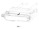
- Figure 1 is a schematic structural view of a typical portable terminal
- Figure 2 is a schematic partial enlarged view of part A in Figure 1
- Figure 3 is a schematic partial enlarged view of part B in Figure 1 .
- the portable terminal generally includes two parts: a main machine 11 and a battery 12. Since in use, the battery 12 needs to be detached from the main machine 11 frequently so as to be charged, repaired or replaced, the battery 12 and the main machine 11 are movably connected.
- Each of the outer side of the top end and the inner side of the tail end of the main machine 11 as shown in Figure 1 has an engaging groove 111 open to a respective side face, and the main machine 11 has an opening configured to receive the bottom portion of the battery 12.
- the battery 12 When being mounted, the battery 12 is pushed forwards along an axial direction of the opening from the tail end of the main machine 11, so that the top end of the battery 12 abuts against the top end of the main machine 11.
- each of both sides of the top end of the battery 12 has a sliding catch (not shown in Figure 1 ) engaged with the respective engaging groove 111 at the top end of the main machine 11, and the tail end of the battery 12 also has a sliding catch 121 engaged with the respective engaging groove 111 at the tail end of the main machine 11. Then, after the sliding catch engages with the engaging groove 111, the battery 12 cannot move leftwards and rightwards or upwards and downwards relative to the main machine 11; however, the battery 12 may still exit along the axial direction of the opening from the main machine 11.
- a pushing button 13 is further provided.
- the tail end of the main machine 11 as shown in Figure 1 has a groove opened upwards, with the pushing button 13 being placed in the groove.
- the upper portion of the pushing button 13 has a protrusion, and a spring is provided between the pushing button 13 and the bottom portion of the groove.
- a spring is provided between the pushing button 13 and the bottom portion of the groove.
- the protrusion of the pushing button 13 is located above the opening of the groove.
- the tail end of the battery 12 is provided with a groove opened downwards at the position corresponding to the protrusion.
- the pushing button 13 In mounting, the pushing button 13 is pushed downwards, so that the spring is compressed and the protrusion enters within the groove, without limitation to sliding of the battery 12; and after the battery 12 slides into the opening of the main machine 11, the pushing button 13 is released, and is ejected upwards under the elastic force of the spring, so that the protrusion of the pushing button 13 is inserted into the groove of the battery 12, thereby preventing the battery 12 from exiting axially.
- the pushing button 13 and a spring are primarily adopted for preventing the battery 12 from exiting. Due to the elasticity of the spring, the battery 12 is likely to be loosened, resulting in a poor contact of the electrodes of the battery 12. Moreover, when the portable terminal falls off or is stricken, the spring would be compressed under the gravity of the pushing button 13 or the inertia, and as a result, the pushing button 13 fails so that the battery 12 may exit. Furthermore, in the prior art, only a small segment of sliding catch 121 is adopted, resulting in insufficient stability.
- An object of the present application is to provide a portable terminal in which the battery and the main machine body may be fixed firmly so that the battery will not drop off even when the portable terminal encounters situations such as falling off or being stricken, and may be assembled and disassembled easily.
- the present application provides a portable terminal including a main machine body and a battery.
- the main machine body has an opening portion for receiving the bottom portion of the battery.
- the main machine body is engaged with the battery in a transverse direction and a longitudinal direction.
- One of the main machine body and the battery is provided with a pushing button moveable in the longitudinal direction, with a compression spring (27) being provided therebetween.
- the other one of the main machine body and the battery is provided with an engaging groove extending in the longitudinal direction.
- the main machine body and the battery are engaged in an axial direction via the pushing button and the engaging groove.
- the portable terminal further includes a locking cover connected to the pushing button.
- a torsion spring is provided between the locking cover and the pushing button, such that the locking cover and the pushing button rotate about the axis of the spring body of the torsion spring.
- the longitudinal distance between one end of the locking cover and the battery or the main machine body provided with the compression spring is less than the distance by which the pushing button is inserted into the engaging groove.
- the pushing button has an axial protrusion
- the locking cover is hinged with the protrusion by a rotating shaft.
- the rotating shaft extends transversely through the protrusion, and the spring body of the torsion spring extends throughout the rotating shaft.
- the locking cover has two clamping arms located at both sides of the protrusion respectively, and the rotating shaft extends through the two clamping arms and the protrusion.
- the torsion spring is a double torsion spring, and two spring arms located at a side of the double torsion spring are connected to the two clamping arms respectively.
- each of the both sides of the main machine body has a sliding groove extending axially and opened outwards, and each of the both sides of the battery has a rib engaged in the corresponding sliding groove and sliding in an axial direction of the sliding groove.
- the sliding grooves are located outside of the both sides of the main machine body, and the ribs are located inside of the both sides of the battery.
- the battery includes a cell body and a shell for loading the cell body.
- the shell includes a battery top shell and a battery bottom shell.
- the battery bottom shell is located in the opening portion, and the rib is located at each of side edges of the battery top shell, and one end of the locking cover abuts against the top portion of the tail end of the battery top shell.
- a torque may be applied to the torsion spring, so that a force may be applied to one end of the locking cover, and the locking cover may be turned relative to the pushing button.
- the longitudinal distance between one end of the locking cover and the battery or the main machine body does not limit the longitudinal movement of the pushing button anymore, and then the pushing button is pushed to compress the compression spring, so that the bottom portion of the battery is allowed to abut against the bottom portion of the main machine body. After the bottom portion of the battery abuts against the bottom portion of the main machine body, the pushing button and the locking cover are released.
- the pushing button stretches out under the elastic force of the compression spring to be engaged with the engaging groove of the main machine body or the battery; and on the other hand, the locking cover returns to be in the initial state under the returning action of the torsion spring.
- the pushing button cannot exit from the engaging groove and is in the deadlocked state, thereby achieving double axial engagement between the battery and the main machine body. Even when the portable apparatus falls off or is stricken, the pushing button will not exit entirely from the engaging groove, that is, the pushing button may still lock the battery and the main machine body reliably.
- the locking cover is returned, and the pushing button is pushed to compress the compression spring, so that the pushing button is disengaged from the engaging groove of the main machine body or the battery. Consequently, the battery may exit from the opening portion of the main machine body.
- the outer portion of the pushing button may have an axial protrusion.
- the locking cover is connected to the protrusion via a torsion spring.
- a transverse rotating shaft is provided on the protrusion, and the locking cover is hinged with the protrusion via the transverse rotating shaft. Since the protrusion extends by a certain distance in the axial direction, the locking cover is facilitated to be turned about the axis of the spring body of the torsion spring without being limited by other structures. Besides, since the locking cover is hinged with the protrusion via the transverse rotating shaft, the connection of the double torsion spring may be simplified.
- the main machine body has a sliding groove located at each of its both outer sides, with the sliding groove being opened outwards, and correspondingly, a rib is provided inside of each of the both sides of the shell of the battery.
- the top end of the battery slides gradually into the opening portion from the tail end of the main machine body, till the top end of the battery and the top end of the main machine body abut against each other.
- two sides of the battery and two sides of the main machine body are respectively engaged along the whole axial length of the sliding grooves, so that the main machine body and the battery may be fixed firmly in a transverse direction and a longitudinal direction.
- the engaging groove is located at an outer side of the main machine body, which may prevent the outside dust, moisture or other foreign matters from entering the space between the battery and main machine body, so as to ensure the service performance of the portable terminal apparatus.
- Figure 1 is a schematic structural view of a typical portable terminal
- Figure 2 is a schematic partial enlarged view of part A in Figure 1 ;
- Figure 3 is a schematic partial enlarged view of part B in Figure 1 ;
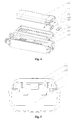
- Figure 4 is a schematic exploded structural view of an assembly of a specific embodiment of a portable terminal according to the present application.
- Figure 5 is a schematic cross-sectional view of the portable terminal shown in Figure 4 ;
- Figure 6 is a right view showing the tail end of the portable terminal shown in Figure 4 ;
- Figure 7 is a schematic view showing the principle of the structure in Figure 6 ;
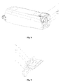
- Figure 8 is a schematic structural view of the portable terminal shown in Figure 4 ;
- Figure 9 is a schematic structural view showing the pushing button fitted with the locking cover in another specific embodiment of the portable terminal according to the present application.
- FIG. 10 is a schematic view showing the battery fitted with the main machine body in still another specific embodiment of the portable terminal according to the present application.
- Figure 11 is a schematic view taken along line C of Figure 10 .
- An object of the present application is to provide a portable terminal in which the battery and the main machine body may be fixed firmly so that the battery will not drop off even when the portable terminal encounters situations such as falling off or being stricken, and may be assembled and disassembled easily.
- Figure 4 is a schematic exploded structural view of an assembly of a specific embodiment of a portable terminal according to the present application
- Figure 5 is a schematic cross-sectional view of the portable terminal shown in Figure 4
- Figure 6 is a right view showing the tail end of the portable terminal shown in Figure 4
- Figure 7 is a schematic view showing the principle of the structure in Figure 6
- Figure 8 is a schematic structural view of the portable terminal shown in Figure 4 .
- a portable terminal includes a main machine body 21 and a battery 22.
- the main machine body 21 has an opening portion for receiving the bottom portion of the battery 22.
- only the bottom portion of the battery 22 is located in the opening portion.
- the main machine body 21 is engaged with the battery 22 in a transverse direction and a longitudinal direction.
- the transverse direction is a direction perpendicular to an axial direction of the opening portion in the opening plane of the opening portion
- the longitudinal direction is a direction perpendicular to the opening plane of the opening portion.
- the longitudinal direction is a vertical direction of the portable terminal.
- an engaging groove open to a respective side face may be machined at each of both sides of the top end and of the tail end of the main machine body 21, and a structure adapted to be inserted into the respective engaging groove may be machined at each of both sides of the top end and of the tail end of the battery 22, so that the battery 22 may be pushed into the opening portion from a rear end of the main machine body 21 and cannot move leftwards and rightwards (transversely), upwards and downwards (longitudinally) relative to the main machine body 21.
- the top end of the battery 22 abuts against the top end of the main machine body 21, so that the battery 22 may exit from the tail end of the main machine body 21 only along the opening portion.
- the main machine body 21 may be provided with a pushing button 24 moving in the longitudinal direction, and a compression spring 27 is provided between the main machine body 21 and the pushing button 24.
- the battery 22 may be provided with an engaging groove extending in the longitudinal direction, so that the main machine body 21 is engaged with the battery 22 in the axial direction via the pushing button 24 and the engaging groove.
- the tail end of the battery 21 may have a pushing button 24 moving in the longitudinal direction, and a compression spring 27 may be provided between the battery 21 and the pushing button 24.
- the lower end of the pushing button 24 may be inserted into the engaging groove of the main machine body 21, so that the battery 22 is incapable of exiting in the axial direction of the opening portion due to the limitation of the pushing button 24.
- the pushing button 24 When the battery 22 is disassembled, the pushing button 24 is pushed upwards, and the compression spring 27 is compressed, so that the lower end of the pushing button 24 is disengaged from the engaging groove of the main machine body 21, thereby allowing the axial movement of the battery 22 without the limitation of the pushing button 24. In this way, the battery 22 may exit from the opening portion.
- the pushing button 24 In mounting, the pushing button 24 is pushed upwards until the battery 22 is mounted in the opening portion, and then is released, so that the pushing button 24 moves downwards due to the returning action of the compression spring 27 and then the lower portion of the pushing button 24 is engaged in the engaging groove of the tail end of the main machine body 21, causing that the battery 22 is incapable of exiting.
- the portable terminal further includes a locking cover 25, with a torsion spring 23 being provided between the locking cover 25 and the pushing button 24.
- the torsion spring 23 is provided between the outer side of the pushing button 24 and the locking cover 25.
- the outer side of the pushing button 24 is the portion of the pushing button 24 facing outwards after the pushing button 24 is assembled.
- the pushing button 24 may rotate about the axis of the spring body of the torsion spring 23 relative to the locking cover 25; and when the torsion spring 23 is in a return state without being applied with the torque, the longitudinal distance between one end of the locking cover 25 and the battery 22 or the main machine body 21 provided with the compression spring 27 is less than the distance by which the pushing button 24 is inserted into the engaging groove.
- the compression spring 27 is arranged at the tail end of the battery 22, and the upper end of the locking cover 25 abuts against the tail end of the battery 22 when the torsion spring 23 is returned, so that the pushing button 24 connected with the locking cover 25 cannot move upwards.
- the lower end of the pushing button 24 abuts against the bottom portion of the engaging groove of the main machine body 21, so that the pushing button 24 cannot move downwards.
- the pushing button 24 is in a rigid deadlocked state.
- the upper end of the locking cover 25 abuts against the tail end of the battery 22 when the torsion spring 23 is returned, so long as the longitudinal distance between the upper end of the locking cover 25 and the tail end of the battery 22 is less than the distance by which the pushing button 24 is inserted into the engaging groove of the main machine body 21, that is, the pushing button 24 may move upwards by a small distance, but cannot exit from the engaging groove of the main machine body 21.
- a torque may be applied to the torsion spring 23, so that a force may be applied to one end of the locking cover 25, and the locking cover 25 may be turned relative to the pushing button 24.
- the longitudinal distance between one end of the locking cover 25 and the battery 22 or the main machine body 21 does not limit the longitudinal movement of the pushing button 24 anymore, and then the pushing button 24 is pushed to compress the compression spring 27, so that the bottom portion of the battery 22 is allowed to abut against the bottom portion of the main machine body 21.
- the pushing button 24 and the locking cover 25 are released.
- the pushing button 24 stretches out under the elastic force of the compression spring 27 to be engaged with the engaging groove of the main machine body 21 or the battery 22; and on the other hand, the locking cover 25 returns to be in the initial state under the returning action of the torsion spring 23.
- the locking cover 25 as shown in Figure 7 abuts against the tail end of the battery 22 again, so that the pushing button 24 cannot move and is in the deadlocked state, thereby achieving double axial engagement between the battery 22 and the main machine body 21. Even when the portable apparatus falls off or is stricken, the pushing button 24 will not exit entirely from the engaging groove, that is, the pushing button 24 may still lock the battery 22 and the main machine body 21 reliably.
- the locking cover 25 is returned, and the pushing button 24 is pushed to compress the compression spring 27, so that the pushing button 24 is disengaged from the engaging groove of the main machine body 21 or the battery 22. Consequently, the battery 22 may exit from the opening portion of the main machine body 21.
- Figure 9 is a schematic structural view showing the pushing button fitted with the locking cover in another specific embodiment of the portable terminal according to the present application.
- the outer side of the pushing button 24 may be provided with an axial protrusion 241, and the locking cover 25 is connected to the protrusion 241 via a torsion spring 23. Since the protrusion 241 extends by a certain distance in the axial direction, the locking cover 25 is facilitated to be turned about the axis of the spring body of the torsion spring 23 without being limited by other structures.
- a transverse rotating shaft 26 may further be arranged on the protrusion 241, and the locking cover 25 is hinged with the protrusion 241 by the transverse rotating shaft 26.
- the double torsion spring 23 may result in simpler connection.
- the locking cover 25 may have two clamping arms located at both sides of the protrusion 241 respectively, and the rotating shaft 26 passes through the two clamping arms and the protrusion 241.
- the torsion spring 23 is a double torsion spring. Two spring arms located at a side of the double torsion spring abut against the two clamping arms respectively, and the spring arms on the other side of the double torsion spring are connected to the pushing button 24.
- two axial through holes arranged transversely in parallel may be machined at the middle portion of the pushing button 24, and then the transverse spring arms of the double torsion spring 23 may be located at the inner side of the pushing button 24, and the two spring arms opposing to the transverse spring arms are located at the outer side of the pushing button 24 so as to abut against the two clamping arms of the locking cover 25 located at the outer side of the pushing button 24.
- the axial through hole facilitates turning the locking cover 25, for example, the locking cover 25 is rotated anticlockwise by 90°.
- the two spring arms of the locking cover 25 may be rotated into the axial through holes of the pushing button 24, and then the locking cover 25 may be pushed upwards, so as to drive the pushing button 24 to compress the compression spring 27 and thus to be disengaged from the engaging groove of the tail end of the main machine body 21.
- the battery 22 may exit in the axial direction of the opening portion.
- the locking cover 25 is rotated anticlockwise by 90° and then pushed upwards; and after the battery 22 is mounted into the opening portion, the locking cover 25 is released, so that the pushing button 24 is engaged in the engaging groove.
- the locking cover 25 may be rotated by any angle, so long as the angle of the rotation enables the locking cover 25 not to abut against the battery 22 or the main machine body 21 and enables the pushing button 24 to be retracted.
- the locking cover 25 may rotate to a large extent, and may also act as a component for urging the pushing button 24, so that the double deadlocked process and the unlocking process may be performed continuously, resulting in easier operation. Furthermore, such a structure may be easily machined without influencing the appearance of the portable terminal.
- Each of the both sides of the main machine body 21 may have a sliding groove 211 extending axially and opened outwards, and each of the both sides of the battery 22 may have a rib 2211 mated with the corresponding sliding groove 211, so that the rib 2211 may be engaged in the corresponding sliding groove 211 and may slide in the axial direction of the sliding groove 211.
- the top end of the battery 22 slides gradually into the opening portion from the tail end of the main machine body 21, till the top end of the battery 22 and the top end of the main machine body 21 abut against each other.
- both sides of the battery 22 and both sides of the main machine body 21 are respectively engaged along the whole axial length of the sliding grooves 211, so that the main machine body 21 and the battery 22 may be fixed firmly in the transverse direction and the longitudinal direction.
- Figure 10 is a schematic view showing the battery fitted with the main machine body in still another specific embodiment of the portable terminal according to the present application; and Figure 11 is a schematic view taken along line C of Figure 10 .
- the sliding groove 211 may be located outside of the respective sides of the main machine body 21, and may be opened outwards.
- the rib 2211 may be located inside of the respective sides of a shell of the battery 22.
- the upper portion of the battery 22 engagingly covers the main machine body 21.
- Such a structure may prevent the outside dust, moisture or other foreign matters from entering the space between the battery 22 and the main machine body 21, so as to ensure the service performance of the portable terminal apparatus.
- a sliding groove 211 opened inwards may be provided inside of each of the both sides of the main machine body 21, and correspondingly, the rib 2211 may be located at outside of each of the both sides of the battery 22, thereby also achieving the object of the present application.
- the battery 22 may include a cell body and a shell for loading the cell body.
- the cell body may be referred as a power supply.
- the shell may include a battery top shell 221 and a battery bottom shell 222. As shown in Figure 4 .
- the battery bottom shell 222 and the battery top shell 221 are engaged and connected together to form an integrated piece, and then slide into the opening portion of the main machine body 21 along the sliding groove 211.
- the battery bottom shell 222 is located in the opening portion, and the rib 2211 is located at each of side edges of the battery top shell 221, and one end of the locking cover 25 abuts against the tail end of the battery top shell 221.
Landscapes
- Chemical & Material Sciences (AREA)
- Chemical Kinetics & Catalysis (AREA)
- Electrochemistry (AREA)
- General Chemical & Material Sciences (AREA)
- Engineering & Computer Science (AREA)
- Signal Processing (AREA)
- Life Sciences & Earth Sciences (AREA)
- Biophysics (AREA)
- Computer Hardware Design (AREA)
- Microelectronics & Electronic Packaging (AREA)
- Telephone Set Structure (AREA)
- Battery Mounting, Suspending (AREA)
Abstract
Description
- The present application relates to the technical field of electronic products, and particularly to a portable terminal.
- With the rapid development of electronic technology, the application of a portable terminal apparatus has become increasingly wider, for example, in walkie-talkies, mobile phones and other electronic products.
- As shown in
Figures 1 ,2 and3 ,Figure 1 is a schematic structural view of a typical portable terminal;Figure 2 is a schematic partial enlarged view of part A inFigure 1 ; andFigure 3 is a schematic partial enlarged view of part B inFigure 1 . - The portable terminal generally includes two parts: a
main machine 11 and abattery 12. Since in use, thebattery 12 needs to be detached from themain machine 11 frequently so as to be charged, repaired or replaced, thebattery 12 and themain machine 11 are movably connected. Each of the outer side of the top end and the inner side of the tail end of themain machine 11 as shown inFigure 1 has anengaging groove 111 open to a respective side face, and themain machine 11 has an opening configured to receive the bottom portion of thebattery 12. When being mounted, thebattery 12 is pushed forwards along an axial direction of the opening from the tail end of themain machine 11, so that the top end of thebattery 12 abuts against the top end of themain machine 11. Also, each of both sides of the top end of thebattery 12 has a sliding catch (not shown inFigure 1 ) engaged with the respectiveengaging groove 111 at the top end of themain machine 11, and the tail end of thebattery 12 also has asliding catch 121 engaged with the respectiveengaging groove 111 at the tail end of themain machine 11. Then, after the sliding catch engages with theengaging groove 111, thebattery 12 cannot move leftwards and rightwards or upwards and downwards relative to themain machine 11; however, thebattery 12 may still exit along the axial direction of the opening from themain machine 11. Thus, a pushingbutton 13 is further provided. The tail end of themain machine 11 as shown inFigure 1 has a groove opened upwards, with the pushingbutton 13 being placed in the groove. The upper portion of the pushingbutton 13 has a protrusion, and a spring is provided between the pushingbutton 13 and the bottom portion of the groove. When the spring is not pressed, the protrusion of the pushingbutton 13 is located above the opening of the groove. The tail end of thebattery 12 is provided with a groove opened downwards at the position corresponding to the protrusion. In mounting, the pushingbutton 13 is pushed downwards, so that the spring is compressed and the protrusion enters within the groove, without limitation to sliding of thebattery 12; and after thebattery 12 slides into the opening of themain machine 11, the pushingbutton 13 is released, and is ejected upwards under the elastic force of the spring, so that the protrusion of the pushingbutton 13 is inserted into the groove of thebattery 12, thereby preventing thebattery 12 from exiting axially. - However, in the prior art, the pushing
button 13 and a spring are primarily adopted for preventing thebattery 12 from exiting. Due to the elasticity of the spring, thebattery 12 is likely to be loosened, resulting in a poor contact of the electrodes of thebattery 12. Moreover, when the portable terminal falls off or is stricken, the spring would be compressed under the gravity of the pushingbutton 13 or the inertia, and as a result, the pushingbutton 13 fails so that thebattery 12 may exit. Furthermore, in the prior art, only a small segment of slidingcatch 121 is adopted, resulting in insufficient stability. - Thus, it is a technical problem to be addressed by the person skilled in the art to provide a portable terminal in which the battery and the main machine may be fixed firmly and assembled and disassembled easily.
- An object of the present application is to provide a portable terminal in which the battery and the main machine body may be fixed firmly so that the battery will not drop off even when the portable terminal encounters situations such as falling off or being stricken, and may be assembled and disassembled easily.
- For addressing the above technical problems, the present application provides a portable terminal including a main machine body and a battery. The main machine body has an opening portion for receiving the bottom portion of the battery. The main machine body is engaged with the battery in a transverse direction and a longitudinal direction. One of the main machine body and the battery is provided with a pushing button moveable in the longitudinal direction, with a compression spring (27) being provided therebetween. The other one of the main machine body and the battery is provided with an engaging groove extending in the longitudinal direction. The main machine body and the battery are engaged in an axial direction via the pushing button and the engaging groove. The portable terminal further includes a locking cover connected to the pushing button. A torsion spring is provided between the locking cover and the pushing button, such that the locking cover and the pushing button rotate about the axis of the spring body of the torsion spring. When the torsion spring is returned, the longitudinal distance between one end of the locking cover and the battery or the main machine body provided with the compression spring is less than the distance by which the pushing button is inserted into the engaging groove.
- Preferably, the pushing button has an axial protrusion, and the locking cover is hinged with the protrusion by a rotating shaft. The rotating shaft extends transversely through the protrusion, and the spring body of the torsion spring extends throughout the rotating shaft.
- Preferably, the locking cover has two clamping arms located at both sides of the protrusion respectively, and the rotating shaft extends through the two clamping arms and the protrusion. The torsion spring is a double torsion spring, and two spring arms located at a side of the double torsion spring are connected to the two clamping arms respectively.
- Preferably, each of the both sides of the main machine body has a sliding groove extending axially and opened outwards, and each of the both sides of the battery has a rib engaged in the corresponding sliding groove and sliding in an axial direction of the sliding groove.
- Preferably, the sliding grooves are located outside of the both sides of the main machine body, and the ribs are located inside of the both sides of the battery.
- Preferably, the battery includes a cell body and a shell for loading the cell body. The shell includes a battery top shell and a battery bottom shell. The battery bottom shell is located in the opening portion, and the rib is located at each of side edges of the battery top shell, and one end of the locking cover abuts against the top portion of the tail end of the battery top shell.
- When the portable terminal according to the present application is mounted, a torque may be applied to the torsion spring, so that a force may be applied to one end of the locking cover, and the locking cover may be turned relative to the pushing button. Thus, the longitudinal distance between one end of the locking cover and the battery or the main machine body does not limit the longitudinal movement of the pushing button anymore, and then the pushing button is pushed to compress the compression spring, so that the bottom portion of the battery is allowed to abut against the bottom portion of the main machine body. After the bottom portion of the battery abuts against the bottom portion of the main machine body, the pushing button and the locking cover are released. As a result, on the one hand, the pushing button stretches out under the elastic force of the compression spring to be engaged with the engaging groove of the main machine body or the battery; and on the other hand, the locking cover returns to be in the initial state under the returning action of the torsion spring. Thus, the pushing button cannot exit from the engaging groove and is in the deadlocked state, thereby achieving double axial engagement between the battery and the main machine body. Even when the portable apparatus falls off or is stricken, the pushing button will not exit entirely from the engaging groove, that is, the pushing button may still lock the battery and the main machine body reliably. In disassembling, similarly, the locking cover is returned, and the pushing button is pushed to compress the compression spring, so that the pushing button is disengaged from the engaging groove of the main machine body or the battery. Consequently, the battery may exit from the opening portion of the main machine body.
- In a specific embodiment, the outer portion of the pushing button may have an axial protrusion. The locking cover is connected to the protrusion via a torsion spring. A transverse rotating shaft is provided on the protrusion, and the locking cover is hinged with the protrusion via the transverse rotating shaft. Since the protrusion extends by a certain distance in the axial direction, the locking cover is facilitated to be turned about the axis of the spring body of the torsion spring without being limited by other structures. Besides, since the locking cover is hinged with the protrusion via the transverse rotating shaft, the connection of the double torsion spring may be simplified.
- In another specific embodiment, the main machine body has a sliding groove located at each of its both outer sides, with the sliding groove being opened outwards, and correspondingly, a rib is provided inside of each of the both sides of the shell of the battery. In mounting, the top end of the battery slides gradually into the opening portion from the tail end of the main machine body, till the top end of the battery and the top end of the main machine body abut against each other. Here, two sides of the battery and two sides of the main machine body are respectively engaged along the whole axial length of the sliding grooves, so that the main machine body and the battery may be fixed firmly in a transverse direction and a longitudinal direction. Furthermore, the engaging groove is located at an outer side of the main machine body, which may prevent the outside dust, moisture or other foreign matters from entering the space between the battery and main machine body, so as to ensure the service performance of the portable terminal apparatus.
-
Figure 1 is a schematic structural view of a typical portable terminal; -
Figure 2 is a schematic partial enlarged view of part A inFigure 1 ; -
Figure 3 is a schematic partial enlarged view of part B inFigure 1 ; -
Figure 4 is a schematic exploded structural view of an assembly of a specific embodiment of a portable terminal according to the present application; -
Figure 5 is a schematic cross-sectional view of the portable terminal shown inFigure 4 ; -
Figure 6 is a right view showing the tail end of the portable terminal shown inFigure 4 ; -
Figure 7 is a schematic view showing the principle of the structure inFigure 6 ; -
Figure 8 is a schematic structural view of the portable terminal shown inFigure 4 ; -
Figure 9 is a schematic structural view showing the pushing button fitted with the locking cover in another specific embodiment of the portable terminal according to the present application; -
Figure 10 is a schematic view showing the battery fitted with the main machine body in still another specific embodiment of the portable terminal according to the present application; and -
Figure 11 is a schematic view taken along line C ofFigure 10 . - An object of the present application is to provide a portable terminal in which the battery and the main machine body may be fixed firmly so that the battery will not drop off even when the portable terminal encounters situations such as falling off or being stricken, and may be assembled and disassembled easily.
- For those skilled in the art to understand better the technical solutions of the present application, the present application will be further described below in detail in conjunction with the accompanying drawings and the specific embodiments.
- Referring to
Figures 4 to 8 ,Figure 4 is a schematic exploded structural view of an assembly of a specific embodiment of a portable terminal according to the present application;Figure 5 is a schematic cross-sectional view of the portable terminal shown inFigure 4 ;Figure 6 is a right view showing the tail end of the portable terminal shown inFigure 4 ;Figure 7 is a schematic view showing the principle of the structure inFigure 6 ; andFigure 8 is a schematic structural view of the portable terminal shown inFigure 4 . - A portable terminal according to the present application includes a
main machine body 21 and abattery 22. Themain machine body 21 has an opening portion for receiving the bottom portion of thebattery 22. In the portable terminal shown inFigure 8 , only the bottom portion of thebattery 22 is located in the opening portion. Themain machine body 21 is engaged with thebattery 22 in a transverse direction and a longitudinal direction. The transverse direction is a direction perpendicular to an axial direction of the opening portion in the opening plane of the opening portion, and the longitudinal direction is a direction perpendicular to the opening plane of the opening portion. In the case of respective ofFigure 4 , the longitudinal direction is a vertical direction of the portable terminal. For example, an engaging groove open to a respective side face may be machined at each of both sides of the top end and of the tail end of themain machine body 21, and a structure adapted to be inserted into the respective engaging groove may be machined at each of both sides of the top end and of the tail end of thebattery 22, so that thebattery 22 may be pushed into the opening portion from a rear end of themain machine body 21 and cannot move leftwards and rightwards (transversely), upwards and downwards (longitudinally) relative to themain machine body 21. After thebattery 22 is placed into the opening portion, the top end of thebattery 22 abuts against the top end of themain machine body 21, so that thebattery 22 may exit from the tail end of themain machine body 21 only along the opening portion. Themain machine body 21 may be provided with a pushingbutton 24 moving in the longitudinal direction, and acompression spring 27 is provided between themain machine body 21 and the pushingbutton 24. Thebattery 22 may be provided with an engaging groove extending in the longitudinal direction, so that themain machine body 21 is engaged with thebattery 22 in the axial direction via the pushingbutton 24 and the engaging groove. Of course, as shown inFigures 5 and6 , the tail end of thebattery 21 may have a pushingbutton 24 moving in the longitudinal direction, and acompression spring 27 may be provided between thebattery 21 and the pushingbutton 24. The lower end of the pushingbutton 24 may be inserted into the engaging groove of themain machine body 21, so that thebattery 22 is incapable of exiting in the axial direction of the opening portion due to the limitation of the pushingbutton 24. When thebattery 22 is disassembled, the pushingbutton 24 is pushed upwards, and thecompression spring 27 is compressed, so that the lower end of the pushingbutton 24 is disengaged from the engaging groove of themain machine body 21, thereby allowing the axial movement of thebattery 22 without the limitation of the pushingbutton 24. In this way, thebattery 22 may exit from the opening portion. In mounting, the pushingbutton 24 is pushed upwards until thebattery 22 is mounted in the opening portion, and then is released, so that the pushingbutton 24 moves downwards due to the returning action of thecompression spring 27 and then the lower portion of the pushingbutton 24 is engaged in the engaging groove of the tail end of themain machine body 21, causing that thebattery 22 is incapable of exiting. - The portable terminal further includes a locking
cover 25, with atorsion spring 23 being provided between the lockingcover 25 and the pushingbutton 24. Preferably, thetorsion spring 23 is provided between the outer side of the pushingbutton 24 and the lockingcover 25. The outer side of the pushingbutton 24 is the portion of the pushingbutton 24 facing outwards after the pushingbutton 24 is assembled. When a torque is applied to thetorsion spring 23, the pushingbutton 24 may rotate about the axis of the spring body of thetorsion spring 23 relative to the lockingcover 25; and when thetorsion spring 23 is in a return state without being applied with the torque, the longitudinal distance between one end of the lockingcover 25 and thebattery 22 or themain machine body 21 provided with thecompression spring 27 is less than the distance by which the pushingbutton 24 is inserted into the engaging groove. As shown inFigure 7 , thecompression spring 27 is arranged at the tail end of thebattery 22, and the upper end of the lockingcover 25 abuts against the tail end of thebattery 22 when thetorsion spring 23 is returned, so that the pushingbutton 24 connected with the lockingcover 25 cannot move upwards. Also, the lower end of the pushingbutton 24 abuts against the bottom portion of the engaging groove of themain machine body 21, so that the pushingbutton 24 cannot move downwards. Thus, the pushingbutton 24 is in a rigid deadlocked state. In fact, it is not necessary that the upper end of the lockingcover 25 abuts against the tail end of thebattery 22 when thetorsion spring 23 is returned, so long as the longitudinal distance between the upper end of the lockingcover 25 and the tail end of thebattery 22 is less than the distance by which the pushingbutton 24 is inserted into the engaging groove of themain machine body 21, that is, the pushingbutton 24 may move upwards by a small distance, but cannot exit from the engaging groove of themain machine body 21. - In mounting, a torque may be applied to the
torsion spring 23, so that a force may be applied to one end of the lockingcover 25, and the lockingcover 25 may be turned relative to the pushingbutton 24. Thus, the longitudinal distance between one end of the lockingcover 25 and thebattery 22 or themain machine body 21 does not limit the longitudinal movement of the pushingbutton 24 anymore, and then the pushingbutton 24 is pushed to compress thecompression spring 27, so that the bottom portion of thebattery 22 is allowed to abut against the bottom portion of themain machine body 21. After the bottom portion of thebattery 22 abuts against the bottom portion of themain machine body 21, the pushingbutton 24 and the lockingcover 25 are released. As a result, on the one hand, the pushingbutton 24 stretches out under the elastic force of thecompression spring 27 to be engaged with the engaging groove of themain machine body 21 or thebattery 22; and on the other hand, the lockingcover 25 returns to be in the initial state under the returning action of thetorsion spring 23. The lockingcover 25 as shown inFigure 7 abuts against the tail end of thebattery 22 again, so that the pushingbutton 24 cannot move and is in the deadlocked state, thereby achieving double axial engagement between thebattery 22 and themain machine body 21. Even when the portable apparatus falls off or is stricken, the pushingbutton 24 will not exit entirely from the engaging groove, that is, the pushingbutton 24 may still lock thebattery 22 and themain machine body 21 reliably. In disassembling, similarly, the lockingcover 25 is returned, and the pushingbutton 24 is pushed to compress thecompression spring 27, so that the pushingbutton 24 is disengaged from the engaging groove of themain machine body 21 or thebattery 22. Consequently, thebattery 22 may exit from the opening portion of themain machine body 21. - Referring to
Figure 9, Figure 9 is a schematic structural view showing the pushing button fitted with the locking cover in another specific embodiment of the portable terminal according to the present application. - The outer side of the pushing
button 24 may be provided with anaxial protrusion 241, and the lockingcover 25 is connected to theprotrusion 241 via atorsion spring 23. Since theprotrusion 241 extends by a certain distance in the axial direction, the lockingcover 25 is facilitated to be turned about the axis of the spring body of thetorsion spring 23 without being limited by other structures. A transverserotating shaft 26 may further be arranged on theprotrusion 241, and the lockingcover 25 is hinged with theprotrusion 241 by the transverserotating shaft 26. Thedouble torsion spring 23 may result in simpler connection. - As shown in
Figure 9 , the lockingcover 25 may have two clamping arms located at both sides of theprotrusion 241 respectively, and therotating shaft 26 passes through the two clamping arms and theprotrusion 241. Thetorsion spring 23 is a double torsion spring. Two spring arms located at a side of the double torsion spring abut against the two clamping arms respectively, and the spring arms on the other side of the double torsion spring are connected to the pushingbutton 24. As shown inFigure 4 , two axial through holes arranged transversely in parallel may be machined at the middle portion of the pushingbutton 24, and then the transverse spring arms of thedouble torsion spring 23 may be located at the inner side of the pushingbutton 24, and the two spring arms opposing to the transverse spring arms are located at the outer side of the pushingbutton 24 so as to abut against the two clamping arms of the lockingcover 25 located at the outer side of the pushingbutton 24. Furthermore, the axial through hole facilitates turning the lockingcover 25, for example, the lockingcover 25 is rotated anticlockwise by 90°. The two spring arms of the locking cover 25 (in the present embodiment, the two spring arms abut against the tail end of the battery 22) may be rotated into the axial through holes of the pushingbutton 24, and then the lockingcover 25 may be pushed upwards, so as to drive the pushingbutton 24 to compress thecompression spring 27 and thus to be disengaged from the engaging groove of the tail end of themain machine body 21. Here, thebattery 22 may exit in the axial direction of the opening portion. In mounting, similarly, the lockingcover 25 is rotated anticlockwise by 90° and then pushed upwards; and after thebattery 22 is mounted into the opening portion, the lockingcover 25 is released, so that the pushingbutton 24 is engaged in the engaging groove. Of course, it is not necessary to rotate the lockingcover 25 by 90°. That is, the lockingcover 25 may be rotated by any angle, so long as the angle of the rotation enables the lockingcover 25 not to abut against thebattery 22 or themain machine body 21 and enables the pushingbutton 24 to be retracted. In the present embodiment, the lockingcover 25 may rotate to a large extent, and may also act as a component for urging the pushingbutton 24, so that the double deadlocked process and the unlocking process may be performed continuously, resulting in easier operation. Furthermore, such a structure may be easily machined without influencing the appearance of the portable terminal. - Each of the both sides of the
main machine body 21 may have a slidinggroove 211 extending axially and opened outwards, and each of the both sides of thebattery 22 may have arib 2211 mated with the corresponding slidinggroove 211, so that therib 2211 may be engaged in the corresponding slidinggroove 211 and may slide in the axial direction of the slidinggroove 211. When thebattery 22 is mounted, the top end of thebattery 22 slides gradually into the opening portion from the tail end of themain machine body 21, till the top end of thebattery 22 and the top end of themain machine body 21 abut against each other. Here, both sides of thebattery 22 and both sides of themain machine body 21 are respectively engaged along the whole axial length of the slidinggrooves 211, so that themain machine body 21 and thebattery 22 may be fixed firmly in the transverse direction and the longitudinal direction. - Referring to
Figures 10 and 11, Figure 10 is a schematic view showing the battery fitted with the main machine body in still another specific embodiment of the portable terminal according to the present application; andFigure 11 is a schematic view taken along line C ofFigure 10 . - The sliding
groove 211 may be located outside of the respective sides of themain machine body 21, and may be opened outwards. Correspondingly, therib 2211 may be located inside of the respective sides of a shell of thebattery 22. Thus, after being assembled, the upper portion of thebattery 22 engagingly covers themain machine body 21. Such a structure may prevent the outside dust, moisture or other foreign matters from entering the space between thebattery 22 and themain machine body 21, so as to ensure the service performance of the portable terminal apparatus. Alternatively, a slidinggroove 211 opened inwards may be provided inside of each of the both sides of themain machine body 21, and correspondingly, therib 2211 may be located at outside of each of the both sides of thebattery 22, thereby also achieving the object of the present application. - The
battery 22 may include a cell body and a shell for loading the cell body. The cell body may be referred as a power supply. The shell may include abattery top shell 221 and abattery bottom shell 222. As shown inFigure 4 . In assembling, thebattery bottom shell 222 and thebattery top shell 221 are engaged and connected together to form an integrated piece, and then slide into the opening portion of themain machine body 21 along the slidinggroove 211. After being assembled, thebattery bottom shell 222 is located in the opening portion, and therib 2211 is located at each of side edges of thebattery top shell 221, and one end of the lockingcover 25 abuts against the tail end of thebattery top shell 221. - The portable terminal according to the present application has been described above in detail. In the description, the specific examples are used to elaborate the principle and implementations of the present application. It is noted that the above description of the embodiments is provided only for the purpose of better understanding the method and spirit of the present application. It should be noted that, many improvements and modifications can be made by those skilled in the art without departing from the principle of the present invention, and these improvements and modifications also fall within the scope of protection of the application defined by the claims.
Claims (6)
- A portable terminal, comprising a main machine body (21) and a battery (22), wherein the main machine body (21) has an opening portion for receiving a bottom portion of the battery (22) and is engaged with the battery (22) in a transverse direction and a longitudinal direction,
one of the main machine body (21) and the battery (22) is provided with a pushing button (24) moveable in the longitudinal direction, with a compression spring (27) being provided therebetween, and the other one of the main machine body (21) and the battery (22) is provided with an engaging groove extending in the longitudinal direction,
the main machine body (21) and the battery (22) are engaged in an axial direction via the pushing button (24) and the engaging groove, and
wherein the portable terminal further comprises a locking cover (25) connected to the pushing button (24), a torsion spring (23) is provided between the locking cover (25) and the pushing button (24) such that the locking cover (25) and the pushing button (24) rotate about an axis of a spring body of the torsion spring (23), and
when the torsion spring (23) is returned, a longitudinal distance between one end of the locking cover (25) and the battery (22) or the main machine body (21) provided with the compression spring (27) is less than a distance by which the pushing button (24) is inserted into the engaging groove. - The portable terminal according to claim 1, wherein the pushing button (24) has an axial protrusion (241), and the locking cover (25) is hinged with the protrusion (241) by a rotating shaft (26), the rotating shaft (26) extends transversely through the protrusion (241), and the spring body of the torsion spring (23) extends throughout the rotating shaft (26).
- The portable terminal according to claim 2, wherein the locking cover (25) has two clamping arms located at both sides of the protrusion (241) respectively, the rotating shaft (26) extends through the two clamping arms and the protrusion (241), the torsion spring (23) is a double torsion spring, and two spring arms located at a side of the double torsion spring are connected to the two clamping arms respectively.
- The portable terminal according to any one of claims 1 to 3, wherein each of both sides of the main machine body (21) has a sliding groove (211) extending axially and opened outwards, and each of both sides of the battery (22) has a rib (2211) engaged in the corresponding sliding groove (211) and sliding in an axial direction of the sliding groove (211).
- The portable terminal according to claim 4, wherein the sliding grooves are located outside of the both sides of the main machine body (21), and the ribs (2211) are located inside of the both sides of the battery (22).
- The portable terminal according to claim 5, wherein the battery (22) comprises a cell body and a shell for loading the cell body,
the shell comprises a battery top shell (221) and a battery bottom shell (222), and wherein the battery bottom shell (222) is located in the opening portion, the rib (2211) is located at each of side edges of the battery top shell (221), and one end of the locking cover (25) abuts against a top portion of the tail end of the battery top shell (221).
Applications Claiming Priority (1)
| Application Number | Priority Date | Filing Date | Title |
|---|---|---|---|
| PCT/CN2011/071476 WO2012116494A1 (en) | 2011-03-03 | 2011-03-03 | Portable terminal |
Publications (3)
| Publication Number | Publication Date |
|---|---|
| EP2683139A1 true EP2683139A1 (en) | 2014-01-08 |
| EP2683139A4 EP2683139A4 (en) | 2015-01-07 |
| EP2683139B1 EP2683139B1 (en) | 2015-08-12 |
Family
ID=46757353
Family Applications (1)
| Application Number | Title | Priority Date | Filing Date |
|---|---|---|---|
| EP11859957.0A Active EP2683139B1 (en) | 2011-03-03 | 2011-03-03 | Portable terminal |
Country Status (3)
| Country | Link |
|---|---|
| US (1) | US9357664B2 (en) |
| EP (1) | EP2683139B1 (en) |
| WO (1) | WO2012116494A1 (en) |
Cited By (2)
| Publication number | Priority date | Publication date | Assignee | Title |
|---|---|---|---|---|
| CN111740061A (en) * | 2020-07-06 | 2020-10-02 | 深圳中顺新能源科技有限公司 | 5V lithium battery protection structure |
| EP3809514A4 (en) * | 2019-09-04 | 2021-04-21 | Dongguan Amperex Technology Limited | Battery module |
Families Citing this family (12)
| Publication number | Priority date | Publication date | Assignee | Title |
|---|---|---|---|---|
| USD710361S1 (en) * | 2013-01-11 | 2014-08-05 | Bluebird Inc. | Data scan device |
| CN107046113B (en) * | 2017-03-15 | 2023-04-18 | 中科和光(天津)应用激光技术研究所有限公司 | Structure for rapidly replacing battery |
| CN107426368B (en) * | 2017-08-29 | 2023-11-03 | 华勤技术股份有限公司 | Buckling structure and terminal |
| CN107655892B (en) * | 2017-10-31 | 2023-09-12 | 安徽能通新能源科技有限公司 | Lithium battery monitoring device |
| CN110165717A (en) * | 2018-02-11 | 2019-08-23 | 杨龙胜 | A kind of general dorsal clamp type mobile phone charge pal |
| CN109346635B (en) * | 2018-09-29 | 2021-06-01 | 湖北华中光电科技有限公司 | Battery box device with quick disassembly, assembly, locking and sealing functions and use method thereof |
| CN114665898A (en) * | 2020-12-22 | 2022-06-24 | 苏州东华软件科技有限公司 | Small-size wireless terminal equipment that can portable |
| CN112788889B (en) * | 2020-12-22 | 2023-08-11 | 海能达通信股份有限公司 | Communication equipment |
| CN113613439A (en) * | 2021-08-12 | 2021-11-05 | 刘玉帅 | Cardiovascular internal medicine is with respiratory device of dismouting of being convenient for |
| CN114599177A (en) * | 2022-03-08 | 2022-06-07 | 嘉兴昆通科技有限公司 | Emergency rescue positioning terminal |
| CN114865194B (en) * | 2022-05-25 | 2023-11-21 | 武汉氢能与燃料电池产业技术研究院有限公司 | Power supply device |
| CN115242261B (en) * | 2022-08-01 | 2023-09-22 | 成都高新物联网科技有限公司 | Private network handheld terminal |
Family Cites Families (10)
| Publication number | Priority date | Publication date | Assignee | Title |
|---|---|---|---|---|
| JPH07115654A (en) | 1993-10-19 | 1995-05-02 | Matsushita Electric Ind Co Ltd | Automatic convergence device |
| JP2788870B2 (en) * | 1995-05-15 | 1998-08-20 | 埼玉日本電気株式会社 | Battery pack lock structure for mobile phones |
| TWI274288B (en) | 2004-03-04 | 2007-02-21 | Benq Corp | Electronic apparatus and engaging device thereof |
| US20060175840A1 (en) | 2005-02-04 | 2006-08-10 | Fih Co., Ltd | Battery cover latching assembly for portable electronic device |
| CN101546817B (en) * | 2008-03-26 | 2013-08-07 | 深圳富泰宏精密工业有限公司 | Clamping and locking structure for battery cover |
| CN101604734A (en) * | 2008-06-12 | 2009-12-16 | 英业达股份有限公司 | Battery Fixing Mechanism |
| CN101820458A (en) | 2009-02-26 | 2010-09-01 | 深圳富泰宏精密工业有限公司 | Battery cover assembly |
| CN101931671B (en) * | 2009-06-26 | 2013-12-11 | 鸿富锦精密工业(深圳)有限公司 | Electronic device |
| CN101958406B (en) | 2009-07-13 | 2014-10-22 | 赛恩倍吉科技顾问(深圳)有限公司 | Clamping mechanism and portable electronic device using same |
| CN201479188U (en) | 2009-09-15 | 2010-05-19 | 洪越治 | A portable walkie-talkie |
-
2011
- 2011-03-03 WO PCT/CN2011/071476 patent/WO2012116494A1/en not_active Ceased
- 2011-03-03 US US14/002,527 patent/US9357664B2/en active Active
- 2011-03-03 EP EP11859957.0A patent/EP2683139B1/en active Active
Cited By (5)
| Publication number | Priority date | Publication date | Assignee | Title |
|---|---|---|---|---|
| EP3809514A4 (en) * | 2019-09-04 | 2021-04-21 | Dongguan Amperex Technology Limited | Battery module |
| AU2020202328B2 (en) * | 2019-09-04 | 2022-02-17 | Dongguan Amperex Technology Limited | Battery module |
| US11870085B2 (en) | 2019-09-04 | 2024-01-09 | Dongguan Amperex Technology Limited | Fastener-free casing and battery module |
| US12212010B2 (en) | 2019-09-04 | 2025-01-28 | Dongguan Amperex Technology Limited | Fastener-free casing and battery module |
| CN111740061A (en) * | 2020-07-06 | 2020-10-02 | 深圳中顺新能源科技有限公司 | 5V lithium battery protection structure |
Also Published As
| Publication number | Publication date |
|---|---|
| WO2012116494A1 (en) | 2012-09-07 |
| US20130335916A1 (en) | 2013-12-19 |
| EP2683139B1 (en) | 2015-08-12 |
| US9357664B2 (en) | 2016-05-31 |
| EP2683139A4 (en) | 2015-01-07 |
Similar Documents
| Publication | Publication Date | Title |
|---|---|---|
| US9357664B2 (en) | Portable terminal | |
| CN205608398U (en) | Processing case | |
| CN102454692B (en) | Hinge structure and portable electronic device using same | |
| CN107275530B (en) | Electronic device and battery locking device | |
| CN110086490A (en) | Card support structure of electronic equipment and electronic equipment | |
| CN104393740B (en) | Power Adapter | |
| TWM447523U (en) | Portable electronic device and battery module thereof | |
| US9256257B2 (en) | Electronic device and docking station | |
| US9508965B1 (en) | Housing structure with battery cover | |
| US10593914B2 (en) | Battery cover structure for portable optical communication equipment and optical communication equipment | |
| CN102454693A (en) | Hinge structure and portable electronic device using the same | |
| CN102779958B (en) | There is the battery pack locking structure from ejecting function | |
| CN114125640B (en) | Headphone boxes and headphones | |
| CN102562781B (en) | Hinge structure and portable electronic device with the hinge structure | |
| CN102376915A (en) | Electronic equipment and its cell locking device | |
| TW201501856A (en) | Clamping device | |
| CN110645261B (en) | Rotating mechanism and electronic equipment | |
| CN219591736U (en) | Be applied to precious locking of charging head and pop-up mechanism that charges | |
| CN102111466B (en) | Portable terminal | |
| TW201833445A (en) | Unloading mechanism assembly | |
| GB2634365A (en) | Plug pin device | |
| US20110256439A1 (en) | Battery fixing apparatus and electronic device using the same | |
| CN108733144B (en) | Connecting device and electronic equipment | |
| US9104089B2 (en) | Electronic device | |
| CN221468068U (en) | Mobile power supply |
Legal Events
| Date | Code | Title | Description |
|---|---|---|---|
| PUAI | Public reference made under article 153(3) epc to a published international application that has entered the european phase |
Free format text: ORIGINAL CODE: 0009012 |
|
| 17P | Request for examination filed |
Effective date: 20130916 |
|
| AK | Designated contracting states |
Kind code of ref document: A1 Designated state(s): AL AT BE BG CH CY CZ DE DK EE ES FI FR GB GR HR HU IE IS IT LI LT LU LV MC MK MT NL NO PL PT RO RS SE SI SK SM TR |
|
| DAX | Request for extension of the european patent (deleted) | ||
| REG | Reference to a national code |
Ref country code: DE Ref legal event code: R079 Ref document number: 602011018830 Country of ref document: DE Free format text: PREVIOUS MAIN CLASS: H04M0001020000 Ipc: H01M0002100000 |
|
| A4 | Supplementary search report drawn up and despatched |
Effective date: 20141205 |
|
| RIC1 | Information provided on ipc code assigned before grant |
Ipc: H01M 2/10 20060101AFI20141201BHEP Ipc: H04M 1/02 20060101ALI20141201BHEP |
|
| GRAP | Despatch of communication of intention to grant a patent |
Free format text: ORIGINAL CODE: EPIDOSNIGR1 |
|
| INTG | Intention to grant announced |
Effective date: 20150318 |
|
| GRAS | Grant fee paid |
Free format text: ORIGINAL CODE: EPIDOSNIGR3 |
|
| GRAA | (expected) grant |
Free format text: ORIGINAL CODE: 0009210 |
|
| AK | Designated contracting states |
Kind code of ref document: B1 Designated state(s): AL AT BE BG CH CY CZ DE DK EE ES FI FR GB GR HR HU IE IS IT LI LT LU LV MC MK MT NL NO PL PT RO RS SE SI SK SM TR |
|
| REG | Reference to a national code |
Ref country code: GB Ref legal event code: FG4D |
|
| REG | Reference to a national code |
Ref country code: CH Ref legal event code: EP |
|
| REG | Reference to a national code |
Ref country code: AT Ref legal event code: REF Ref document number: 742832 Country of ref document: AT Kind code of ref document: T Effective date: 20150815 |
|
| REG | Reference to a national code |
Ref country code: IE Ref legal event code: FG4D |
|
| REG | Reference to a national code |
Ref country code: DE Ref legal event code: R096 Ref document number: 602011018830 Country of ref document: DE |
|
| REG | Reference to a national code |
Ref country code: LT Ref legal event code: MG4D |
|
| REG | Reference to a national code |
Ref country code: AT Ref legal event code: MK05 Ref document number: 742832 Country of ref document: AT Kind code of ref document: T Effective date: 20150812 |
|
| REG | Reference to a national code |
Ref country code: NL Ref legal event code: MP Effective date: 20150812 |
|
| PG25 | Lapsed in a contracting state [announced via postgrant information from national office to epo] |
Ref country code: FI Free format text: LAPSE BECAUSE OF FAILURE TO SUBMIT A TRANSLATION OF THE DESCRIPTION OR TO PAY THE FEE WITHIN THE PRESCRIBED TIME-LIMIT Effective date: 20150812 Ref country code: NO Free format text: LAPSE BECAUSE OF FAILURE TO SUBMIT A TRANSLATION OF THE DESCRIPTION OR TO PAY THE FEE WITHIN THE PRESCRIBED TIME-LIMIT Effective date: 20151112 Ref country code: LT Free format text: LAPSE BECAUSE OF FAILURE TO SUBMIT A TRANSLATION OF THE DESCRIPTION OR TO PAY THE FEE WITHIN THE PRESCRIBED TIME-LIMIT Effective date: 20150812 Ref country code: GR Free format text: LAPSE BECAUSE OF FAILURE TO SUBMIT A TRANSLATION OF THE DESCRIPTION OR TO PAY THE FEE WITHIN THE PRESCRIBED TIME-LIMIT Effective date: 20151113 Ref country code: LV Free format text: LAPSE BECAUSE OF FAILURE TO SUBMIT A TRANSLATION OF THE DESCRIPTION OR TO PAY THE FEE WITHIN THE PRESCRIBED TIME-LIMIT Effective date: 20150812 |
|
| PG25 | Lapsed in a contracting state [announced via postgrant information from national office to epo] |
Ref country code: SE Free format text: LAPSE BECAUSE OF FAILURE TO SUBMIT A TRANSLATION OF THE DESCRIPTION OR TO PAY THE FEE WITHIN THE PRESCRIBED TIME-LIMIT Effective date: 20150812 Ref country code: RS Free format text: LAPSE BECAUSE OF FAILURE TO SUBMIT A TRANSLATION OF THE DESCRIPTION OR TO PAY THE FEE WITHIN THE PRESCRIBED TIME-LIMIT Effective date: 20150812 Ref country code: IS Free format text: LAPSE BECAUSE OF FAILURE TO SUBMIT A TRANSLATION OF THE DESCRIPTION OR TO PAY THE FEE WITHIN THE PRESCRIBED TIME-LIMIT Effective date: 20151212 Ref country code: AT Free format text: LAPSE BECAUSE OF FAILURE TO SUBMIT A TRANSLATION OF THE DESCRIPTION OR TO PAY THE FEE WITHIN THE PRESCRIBED TIME-LIMIT Effective date: 20150812 Ref country code: ES Free format text: LAPSE BECAUSE OF FAILURE TO SUBMIT A TRANSLATION OF THE DESCRIPTION OR TO PAY THE FEE WITHIN THE PRESCRIBED TIME-LIMIT Effective date: 20150812 Ref country code: HR Free format text: LAPSE BECAUSE OF FAILURE TO SUBMIT A TRANSLATION OF THE DESCRIPTION OR TO PAY THE FEE WITHIN THE PRESCRIBED TIME-LIMIT Effective date: 20150812 Ref country code: PL Free format text: LAPSE BECAUSE OF FAILURE TO SUBMIT A TRANSLATION OF THE DESCRIPTION OR TO PAY THE FEE WITHIN THE PRESCRIBED TIME-LIMIT Effective date: 20150812 Ref country code: PT Free format text: LAPSE BECAUSE OF FAILURE TO SUBMIT A TRANSLATION OF THE DESCRIPTION OR TO PAY THE FEE WITHIN THE PRESCRIBED TIME-LIMIT Effective date: 20151214 |
|
| REG | Reference to a national code |
Ref country code: FR Ref legal event code: PLFP Year of fee payment: 6 |
|
| PG25 | Lapsed in a contracting state [announced via postgrant information from national office to epo] |
Ref country code: NL Free format text: LAPSE BECAUSE OF FAILURE TO SUBMIT A TRANSLATION OF THE DESCRIPTION OR TO PAY THE FEE WITHIN THE PRESCRIBED TIME-LIMIT Effective date: 20150812 |
|
| PG25 | Lapsed in a contracting state [announced via postgrant information from national office to epo] |
Ref country code: CZ Free format text: LAPSE BECAUSE OF FAILURE TO SUBMIT A TRANSLATION OF THE DESCRIPTION OR TO PAY THE FEE WITHIN THE PRESCRIBED TIME-LIMIT Effective date: 20150812 Ref country code: IT Free format text: LAPSE BECAUSE OF FAILURE TO SUBMIT A TRANSLATION OF THE DESCRIPTION OR TO PAY THE FEE WITHIN THE PRESCRIBED TIME-LIMIT Effective date: 20150812 Ref country code: EE Free format text: LAPSE BECAUSE OF FAILURE TO SUBMIT A TRANSLATION OF THE DESCRIPTION OR TO PAY THE FEE WITHIN THE PRESCRIBED TIME-LIMIT Effective date: 20150812 Ref country code: SK Free format text: LAPSE BECAUSE OF FAILURE TO SUBMIT A TRANSLATION OF THE DESCRIPTION OR TO PAY THE FEE WITHIN THE PRESCRIBED TIME-LIMIT Effective date: 20150812 Ref country code: DK Free format text: LAPSE BECAUSE OF FAILURE TO SUBMIT A TRANSLATION OF THE DESCRIPTION OR TO PAY THE FEE WITHIN THE PRESCRIBED TIME-LIMIT Effective date: 20150812 |
|
| REG | Reference to a national code |
Ref country code: DE Ref legal event code: R097 Ref document number: 602011018830 Country of ref document: DE |
|
| PG25 | Lapsed in a contracting state [announced via postgrant information from national office to epo] |
Ref country code: RO Free format text: LAPSE BECAUSE OF FAILURE TO SUBMIT A TRANSLATION OF THE DESCRIPTION OR TO PAY THE FEE WITHIN THE PRESCRIBED TIME-LIMIT Effective date: 20150812 |
|
| PLBE | No opposition filed within time limit |
Free format text: ORIGINAL CODE: 0009261 |
|
| STAA | Information on the status of an ep patent application or granted ep patent |
Free format text: STATUS: NO OPPOSITION FILED WITHIN TIME LIMIT |
|
| 26N | No opposition filed |
Effective date: 20160513 |
|
| PG25 | Lapsed in a contracting state [announced via postgrant information from national office to epo] |
Ref country code: SI Free format text: LAPSE BECAUSE OF FAILURE TO SUBMIT A TRANSLATION OF THE DESCRIPTION OR TO PAY THE FEE WITHIN THE PRESCRIBED TIME-LIMIT Effective date: 20150812 Ref country code: BE Free format text: LAPSE BECAUSE OF NON-PAYMENT OF DUE FEES Effective date: 20160331 |
|
| PG25 | Lapsed in a contracting state [announced via postgrant information from national office to epo] |
Ref country code: MC Free format text: LAPSE BECAUSE OF FAILURE TO SUBMIT A TRANSLATION OF THE DESCRIPTION OR TO PAY THE FEE WITHIN THE PRESCRIBED TIME-LIMIT Effective date: 20150812 Ref country code: LU Free format text: LAPSE BECAUSE OF FAILURE TO SUBMIT A TRANSLATION OF THE DESCRIPTION OR TO PAY THE FEE WITHIN THE PRESCRIBED TIME-LIMIT Effective date: 20160303 |
|
| REG | Reference to a national code |
Ref country code: CH Ref legal event code: PL |
|
| REG | Reference to a national code |
Ref country code: IE Ref legal event code: MM4A |
|
| PG25 | Lapsed in a contracting state [announced via postgrant information from national office to epo] |
Ref country code: BE Free format text: LAPSE BECAUSE OF FAILURE TO SUBMIT A TRANSLATION OF THE DESCRIPTION OR TO PAY THE FEE WITHIN THE PRESCRIBED TIME-LIMIT Effective date: 20150812 |
|
| PG25 | Lapsed in a contracting state [announced via postgrant information from national office to epo] |
Ref country code: IE Free format text: LAPSE BECAUSE OF NON-PAYMENT OF DUE FEES Effective date: 20160303 Ref country code: CH Free format text: LAPSE BECAUSE OF NON-PAYMENT OF DUE FEES Effective date: 20160331 Ref country code: LI Free format text: LAPSE BECAUSE OF NON-PAYMENT OF DUE FEES Effective date: 20160331 |
|
| REG | Reference to a national code |
Ref country code: FR Ref legal event code: PLFP Year of fee payment: 7 |
|
| PG25 | Lapsed in a contracting state [announced via postgrant information from national office to epo] |
Ref country code: MT Free format text: LAPSE BECAUSE OF FAILURE TO SUBMIT A TRANSLATION OF THE DESCRIPTION OR TO PAY THE FEE WITHIN THE PRESCRIBED TIME-LIMIT Effective date: 20150812 |
|
| REG | Reference to a national code |
Ref country code: FR Ref legal event code: PLFP Year of fee payment: 8 |
|
| PG25 | Lapsed in a contracting state [announced via postgrant information from national office to epo] |
Ref country code: CY Free format text: LAPSE BECAUSE OF FAILURE TO SUBMIT A TRANSLATION OF THE DESCRIPTION OR TO PAY THE FEE WITHIN THE PRESCRIBED TIME-LIMIT Effective date: 20150812 Ref country code: HU Free format text: LAPSE BECAUSE OF FAILURE TO SUBMIT A TRANSLATION OF THE DESCRIPTION OR TO PAY THE FEE WITHIN THE PRESCRIBED TIME-LIMIT; INVALID AB INITIO Effective date: 20110303 Ref country code: SM Free format text: LAPSE BECAUSE OF FAILURE TO SUBMIT A TRANSLATION OF THE DESCRIPTION OR TO PAY THE FEE WITHIN THE PRESCRIBED TIME-LIMIT Effective date: 20150812 |
|
| PG25 | Lapsed in a contracting state [announced via postgrant information from national office to epo] |
Ref country code: MT Free format text: LAPSE BECAUSE OF FAILURE TO SUBMIT A TRANSLATION OF THE DESCRIPTION OR TO PAY THE FEE WITHIN THE PRESCRIBED TIME-LIMIT Effective date: 20160331 Ref country code: MK Free format text: LAPSE BECAUSE OF FAILURE TO SUBMIT A TRANSLATION OF THE DESCRIPTION OR TO PAY THE FEE WITHIN THE PRESCRIBED TIME-LIMIT Effective date: 20150812 Ref country code: TR Free format text: LAPSE BECAUSE OF FAILURE TO SUBMIT A TRANSLATION OF THE DESCRIPTION OR TO PAY THE FEE WITHIN THE PRESCRIBED TIME-LIMIT Effective date: 20150812 |
|
| PG25 | Lapsed in a contracting state [announced via postgrant information from national office to epo] |
Ref country code: BG Free format text: LAPSE BECAUSE OF FAILURE TO SUBMIT A TRANSLATION OF THE DESCRIPTION OR TO PAY THE FEE WITHIN THE PRESCRIBED TIME-LIMIT Effective date: 20150812 |
|
| PG25 | Lapsed in a contracting state [announced via postgrant information from national office to epo] |
Ref country code: AL Free format text: LAPSE BECAUSE OF FAILURE TO SUBMIT A TRANSLATION OF THE DESCRIPTION OR TO PAY THE FEE WITHIN THE PRESCRIBED TIME-LIMIT Effective date: 20150812 |
|
| REG | Reference to a national code |
Ref country code: DE Ref legal event code: R079 Ref document number: 602011018830 Country of ref document: DE Free format text: PREVIOUS MAIN CLASS: H01M0002100000 Ipc: H01M0050200000 |
|
| PGFP | Annual fee paid to national office [announced via postgrant information from national office to epo] |
Ref country code: GB Payment date: 20260323 Year of fee payment: 16 |
|
| PGFP | Annual fee paid to national office [announced via postgrant information from national office to epo] |
Ref country code: DE Payment date: 20260313 Year of fee payment: 16 |
|
| PGFP | Annual fee paid to national office [announced via postgrant information from national office to epo] |
Ref country code: FR Payment date: 20260330 Year of fee payment: 16 |