EP2683137B1 - Preventive diagnostic system for gas insulated switchgears GIS based on IEC 61850 - Google Patents
Preventive diagnostic system for gas insulated switchgears GIS based on IEC 61850 Download PDFInfo
- Publication number
- EP2683137B1 EP2683137B1 EP13175178.6A EP13175178A EP2683137B1 EP 2683137 B1 EP2683137 B1 EP 2683137B1 EP 13175178 A EP13175178 A EP 13175178A EP 2683137 B1 EP2683137 B1 EP 2683137B1
- Authority
- EP
- European Patent Office
- Prior art keywords
- das
- iec
- ccu
- diagnostic system
- gis
- Prior art date
- Legal status (The legal status is an assumption and is not a legal conclusion. Google has not performed a legal analysis and makes no representation as to the accuracy of the status listed.)
- Active
Links
Images

Classifications
-
- G—PHYSICS
- G01—MEASURING; TESTING
- G01R—MEASURING ELECTRIC VARIABLES; MEASURING MAGNETIC VARIABLES
- G01R31/00—Arrangements for testing electric properties; Arrangements for locating electric faults; Arrangements for electrical testing characterised by what is being tested not provided for elsewhere
- G01R31/12—Testing dielectric strength or breakdown voltage ; Testing or monitoring effectiveness or level of insulation, e.g. of a cable or of an apparatus, for example using partial discharge measurements; Electrostatic testing
-
- H—ELECTRICITY
- H01—ELECTRIC ELEMENTS
- H01H—ELECTRIC SWITCHES; RELAYS; SELECTORS; EMERGENCY PROTECTIVE DEVICES
- H01H33/00—High-tension or heavy-current switches with arc-extinguishing or arc-preventing means
- H01H33/02—Details
- H01H33/26—Means for detecting the presence of an arc or other discharge
-
- G—PHYSICS
- G01—MEASURING; TESTING
- G01R—MEASURING ELECTRIC VARIABLES; MEASURING MAGNETIC VARIABLES
- G01R31/00—Arrangements for testing electric properties; Arrangements for locating electric faults; Arrangements for electrical testing characterised by what is being tested not provided for elsewhere
- G01R31/327—Testing of circuit interrupters, switches or circuit-breakers
-
- H—ELECTRICITY
- H04—ELECTRIC COMMUNICATION TECHNIQUE
- H04L—TRANSMISSION OF DIGITAL INFORMATION, e.g. TELEGRAPHIC COMMUNICATION
- H04L67/00—Network arrangements or protocols for supporting network services or applications
- H04L67/01—Protocols
- H04L67/12—Protocols specially adapted for proprietary or special-purpose networking environments, e.g. medical networks, sensor networks, networks in vehicles or remote metering networks
-
- H—ELECTRICITY
- H04—ELECTRIC COMMUNICATION TECHNIQUE
- H04L—TRANSMISSION OF DIGITAL INFORMATION, e.g. TELEGRAPHIC COMMUNICATION
- H04L69/00—Network arrangements, protocols or services independent of the application payload and not provided for in the other groups of this subclass
- H04L69/08—Protocols for interworking; Protocol conversion
-
- G—PHYSICS
- G01—MEASURING; TESTING
- G01R—MEASURING ELECTRIC VARIABLES; MEASURING MAGNETIC VARIABLES
- G01R31/00—Arrangements for testing electric properties; Arrangements for locating electric faults; Arrangements for electrical testing characterised by what is being tested not provided for elsewhere
- G01R31/12—Testing dielectric strength or breakdown voltage ; Testing or monitoring effectiveness or level of insulation, e.g. of a cable or of an apparatus, for example using partial discharge measurements; Electrostatic testing
- G01R31/1227—Testing dielectric strength or breakdown voltage ; Testing or monitoring effectiveness or level of insulation, e.g. of a cable or of an apparatus, for example using partial discharge measurements; Electrostatic testing of components, parts or materials
- G01R31/1254—Testing dielectric strength or breakdown voltage ; Testing or monitoring effectiveness or level of insulation, e.g. of a cable or of an apparatus, for example using partial discharge measurements; Electrostatic testing of components, parts or materials of gas-insulated power appliances or vacuum gaps
-
- H—ELECTRICITY
- H02—GENERATION; CONVERSION OR DISTRIBUTION OF ELECTRIC POWER
- H02B—BOARDS, SUBSTATIONS OR SWITCHING ARRANGEMENTS FOR THE SUPPLY OR DISTRIBUTION OF ELECTRIC POWER
- H02B13/00—Arrangement of switchgear in which switches are enclosed in, or structurally associated with, a casing, e.g. cubicle
- H02B13/02—Arrangement of switchgear in which switches are enclosed in, or structurally associated with, a casing, e.g. cubicle with metal casing
- H02B13/035—Gas-insulated switchgear
- H02B13/065—Means for detecting or reacting to mechanical or electrical defects
- H02B13/0655—Means for detecting or reacting to mechanical or electrical defects through monitoring changes of gas properties
-
- H—ELECTRICITY
- H04—ELECTRIC COMMUNICATION TECHNIQUE
- H04L—TRANSMISSION OF DIGITAL INFORMATION, e.g. TELEGRAPHIC COMMUNICATION
- H04L67/00—Network arrangements or protocols for supporting network services or applications
- H04L67/01—Protocols
- H04L67/12—Protocols specially adapted for proprietary or special-purpose networking environments, e.g. medical networks, sensor networks, networks in vehicles or remote metering networks
- H04L67/125—Protocols specially adapted for proprietary or special-purpose networking environments, e.g. medical networks, sensor networks, networks in vehicles or remote metering networks involving control of end-device applications over a network
-
- Y—GENERAL TAGGING OF NEW TECHNOLOGICAL DEVELOPMENTS; GENERAL TAGGING OF CROSS-SECTIONAL TECHNOLOGIES SPANNING OVER SEVERAL SECTIONS OF THE IPC; TECHNICAL SUBJECTS COVERED BY FORMER USPC CROSS-REFERENCE ART COLLECTIONS [XRACs] AND DIGESTS
- Y04—INFORMATION OR COMMUNICATION TECHNOLOGIES HAVING AN IMPACT ON OTHER TECHNOLOGY AREAS
- Y04S—SYSTEMS INTEGRATING TECHNOLOGIES RELATED TO POWER NETWORK OPERATION, COMMUNICATION OR INFORMATION TECHNOLOGIES FOR IMPROVING THE ELECTRICAL POWER GENERATION, TRANSMISSION, DISTRIBUTION, MANAGEMENT OR USAGE, i.e. SMART GRIDS
- Y04S40/00—Systems for electrical power generation, transmission, distribution or end-user application management characterised by the use of communication or information technologies, or communication or information technology specific aspects supporting them
- Y04S40/18—Network protocols supporting networked applications, e.g. including control of end-device applications over a network
Definitions
- the present disclosure relates to a preventive diagnostic system for a GIS based on IEC 61850, and more particularly, to a preventive diagnostic system for a GIS based on IEC 61850 that enables communication between a DAS and a CCU to be made in compliance with the communication specification of IEC 61850 by applying IEC 61850 to the preventive diagnostic system for a GIS.
- a preventive diagnostic system for a gas insulated switchgear is a system that measures gas leakage and partial discharge inside the GIS, which are indications of the breakage of insulation, detects a breakdown in advance, and takes measures thereto.
- IEC International Electrotechnical Commission
- IEC 61850 has not been applied to preventive diagnostic systems for a GIS. Accordingly, there is a problem in that it is difficult to smoothly integrate a conventional preventive diagnostic system for a GIS with a substation automation system to which IEC 61850 is applied and to perform an efficient operation of such a preventive diagnostic system.
- Gao Qiang et al, "High voltage equipment online monitoring system of smart substation", Innovative Smart Grid Technologies - Asia, 2012 IEEE, IEEE, 21 May 2012, pages 1-5 relates to the basic structure and function of the high voltage online monitoring system of a smart substation, and the detailed terms about the monitoring device, comprehensive monitoring unit, substation monitoring unit and communication protocols were covered respectively.
- the system comprises on-line detection equipment and a remote center connected with the on-line detection equipment and is characterized in that the on-line detection equipment comprises a node setting unit, a data acquisition unit and a model uploading unit, wherein the node setting unit is used for completing and expanding the existing standard and carrying out defining of a logic node on detection data according to the preset classification; the data acquisition unit is connected with the node setting unit and is used for carrying out real-time detection on the working condition of a transformer substation according to the node set by the node setting unit and acquiring data; the model uploading unit is respectively connected with the data acquisition unit and the remote center and is used for forming a standard IED (Intelligent Electronic Device) data transmission file by using a descriptive language configurated to the transformer substation and sending the standard IED data transmission file to the remote center.
- IED Intelligent Electronic Device
- a logical node (LN) for the preventive diagnostic system for a GIS is designed.
- a standard model In order for the preventive diagnostic system for a GIS to perform communication in compliance with IEC 61850, information of a standard model is used, and the standard model is configured by a logical node, a logical data acquisition system (DAS), and a common data class (CDC).
- Data objects defined in IEC 61850 are mapped into objects defined in a manufacturing message specification (MMS) and perform MMS communication.
- MMS manufacturing message specification
- a logical DAS is mapped into a domain object
- a logical node and data are mapped into named variable objects
- a data set is mapped into a named variable list.
- a control block is mapped into a control block object, and a log is mapped into a journal object.
- the MMS communication is performed in a form in which information is supplied to an MMS server in accordance with a request from an MMS client.
- the MMS server acquires information matching actual hardware, that is, power facilities as one-to-one relation through A/D conversion and stores the information.
- the stored information is actually stored in variable objects of the MMS server that are data and data attributes and is provided every time when there is a request from a client.
- a logical node for the preventive diagnostic system for a GIS is designed.
- Table 1 illustrates a logical node drawing for the preventive diagnostic system for a GIS illustrated in FIG. 1 as a table.
- M represents an attribute that is essentially configured
- O represents an attribute that may be selectively configured, which are determined based on the implementation.
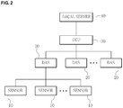
- FIG. 2 is a schematic diagram that illustrates the configuration of a preventive diagnostic system for a GIS based on IEC 61850 according to an embodiment of the present disclosure.
- each partial discharge sensor 10 is installed to the GIS, detects the occurrence of partial discharge, and delivers sensed data to a DAS 20.
- the DAS 20 receives sensed data from a plurality of the partial discharge sensors 10, processes the sensed data, and delivers the processed sensed data to a central communication unit (CCU) 30.
- CCU central communication unit
- the above-described DAS 20 generates an ICD file representing the content of the configuration thereof using the logical node designed for the preventive diagnostic system for a GIS so as to communicate with the CCU 30 in compliance with IEC 61850 and delivers the generated ICD file to the CCU 30.
- the ICD file is an extensible markup language (XML) file configured to have a tag-based structure in the form of a tree, and the content thereof is divided into network information in which an IP address and an MAC address used for MMS communication and general object oriented substation event (GOOSE) communication are set, service information in which functions that may be served in the DAS 20 are defined, logical node information in which information relating to logical nodes provided by the DAS 20 is defined, and report information in which information relating to reports provided by the DAS 20 is defined.
- XML extensible markup language
- the CCU 30 transmits the sensed data received from the DAS's 20 to a local server 40 in real time.
- the above-described CCU 30 makes a network connection for communicating with the DAS 20 in compliance with IEC 61850 in accordance with the content of the ICD file delivered from the DAS 20 and communicates with the DAS 20 in compliance with IEC 61850.
- the local server 40 generates report data using the real-time data received from the CCU 30 and supplies the generated report data to a user through an HMI screen.
- the memory map is defined in a substation configuration description (SCD) file and the ICD file and is applied by downloading necessary files such as the SCD file, the ICD file, an osicfg.xml file, and a logging.xml file from the CCU 30 to the DAS 20.
- SCD substation configuration description
- the existing communication protocol between the DAS 20 and the CCU 30 may be directly reflected on the memory map for IEC 61850.
- an interface with a higher-level system CCU
- an IEC 61850 COM client to which a component object model (COM) technology is applied performs such a role.
- the IEC 61850 COM client has functions for operating or stopping each DAS 20 and performing monitoring, control, and the like of measured values.
- the IEC 61850 COM client is configured to immediately respond when there is a request from a higher-level system.
- Major functions of the IEC 61850 COM client include a function for analyzing and providing the ICD file and the SCD file, a function for operating and stopping each DAS, and a function for controlling and monitoring each DAS.
- the CCU 30 is configured to include a configuration tool, an operation tool, and a value viewer tool.
- the configuration tool has a function for generating a database that is necessary to the system operating, and, as major functions thereof, there are a system configuration function, a tag generation function, and a mapping function.
- the system configuration function configures a gateway system (not illustrated in the figure) to which the DAS 20 is connected and the DAS 20.
- a plurality of DAS's 20 are installed in one gate system, and a maximum number of DAS's 20 is determined based on the capacity of the gateway system.
- the content of the configuration of the DAS 20 follows the international standard specification and, consequently, is stored in the XML format in accordance with the international standards. Thus, all the configurations of the DAS 20 that are compliant with the specification of IEC 61850 may be employed.
- the tag generation function automatically generates tags. All the elements from a higher-level server to a lower-level I/O device have unique names called tags, and these tag names are elements that may be commonly used by mutually-different application programs.
- the mapping function selects a value to be actually used from among many values of the DAS 20.
- All the monitoring elements of the DAS 20 are defined as international standard specifications. While all the monitoring elements may be used, only some of the monitoring elements may be used based on the properties thereof. Accordingly, when all the monitoring elements that are not actually used are managed, there is a large loss of resources, and the efficiency is low. Therefore, it is necessary to select necessary monitoring elements depending on the situation.
- the operation tool is responsible for operating or stopping each DAS 20 and may perform the operating or stopping of DAS's altogether by selecting a higher-level group.
- a DAS 20 is operated or stopped through the operation tool of the CCU 30
- information and a command of the DAS 20 are delivered to the IEC 61850 COM client of the DAS 20.
- the IEC 61850 COM client directly issues a command to the DAS 20 in accordance with the command received from the operation tool of the CCU 30 and responses to the operation tool of the CCU 30 with the state.
- the value viewer tool performs the function of monitoring and controlling a value received from each DAS 20.
- the value viewer tool outputs a current value of the selected DAS 20 in real time.
- the value viewer tool newly generates the value.
- the CCU 30 communicates with the DAS's 20 arranged at the lower end in compliance with IEC 61850 so as to transmit or receive data.
- the local server 40 since a local server 40 that was developed in the past transmits or receives data in a channel data format of 17 frames, the local server cannot transmit or receive data that is in the format of IEC 61850. Accordingly, it is preferable to load an IEC 61850 client, which is a program converting data having the format of IEC 61850 into the channel data format of 17 frames that may be received by the local server 40, into the CCU 30 in consideration of the compatibility with an existing system.
- the above-described IEC 61850 client is configured to be able to perform IEC 61850 communication with DAS's 20 arranged at the lower end by registering "iec_mprocess.dll" as a COM.
- the IEC 61850 client may access the registered COM and extract necessary data of the DAS 20. Through this, the IEC 61850 client may extract data of all the DAS's 20 connected to the lower end of the CCU 30. Thereafter, the IEC 61850 client maps all the data of the DAS's 20 into channel data of 17 frames with being divided into analog tags and digital tags based on Tag_Mst and the mapping table of the database.
- the IEC 61850 client transmits the mapped channel data to the higher-level local server 40.
- the local server 40 receives the data and stores the data in a shared memory such that an HMI and the other servers may access the data.
- the DAS 20 in which a CPU is mounted has been described as an example. However, in a case where the CPU is not mounted in the DAS 20, it is preferable to mount a communication card capable of performing IEC 61850 communication in the DAS 20.
- the preventive diagnostic system for a GIS based on IEC 61850 according to the present disclosure is not limited to the above-described embodiment and may be variously changed within a range allowed by the technical concept of the present disclosure.
Landscapes
- Engineering & Computer Science (AREA)
- Computer Networks & Wireless Communication (AREA)
- Signal Processing (AREA)
- Physics & Mathematics (AREA)
- General Physics & Mathematics (AREA)
- Computer Security & Cryptography (AREA)
- Health & Medical Sciences (AREA)
- Computing Systems (AREA)
- General Health & Medical Sciences (AREA)
- Medical Informatics (AREA)
- Computer And Data Communications (AREA)
- Remote Monitoring And Control Of Power-Distribution Networks (AREA)
- Data Exchanges In Wide-Area Networks (AREA)
- Debugging And Monitoring (AREA)
Description
- The present disclosure relates to a preventive diagnostic system for a GIS based on IEC 61850, and more particularly, to a preventive diagnostic system for a GIS based on IEC 61850 that enables communication between a DAS and a CCU to be made in compliance with the communication specification of IEC 61850 by applying IEC 61850 to the preventive diagnostic system for a GIS.
- Generally, a preventive diagnostic system for a gas insulated switchgear (GIS) is a system that measures gas leakage and partial discharge inside the GIS, which are indications of the breakage of insulation, detects a breakdown in advance, and takes measures thereto.
- The request for a standard protocol for mutual compatibility between facilities inside substations and the automation of substations has increased. Accordingly, in order to constitute a mutual common protocol for easy extension and interfaces of substation facilities domestically and internationally, the International Electrotechnical Commission (IEC) has constituted a substation protocol called IEC 61850.
- Thus, all the power monitoring control equipment installed inside substations are regulated to follow IEC 61850.
- However, currently, IEC 61850 has not been applied to preventive diagnostic systems for a GIS. Accordingly, there is a problem in that it is difficult to smoothly integrate a conventional preventive diagnostic system for a GIS with a substation automation system to which IEC 61850 is applied and to perform an efficient operation of such a preventive diagnostic system.
- Weifeng Xin et al. "Design of intelligent component for high voltage GIS based on IEC61850", Electric Power Equipment - Switching Technology, 2011 1st International Conference on IEEE, 23 October 2011, pages 262-265 relates to a design of intelligent component for HV GIS, especially the IEC61850 communication interface. The intelligent component adopts decentralized control topology to realize the online monitoring of primary equipment, and it has such functions as human-machine interface, local or remote control, logic interlocking and the most important IEC61850 communication interface.
- Gao Qiang et al, "High voltage equipment online monitoring system of smart substation", Innovative Smart Grid Technologies - Asia, 2012 IEEE, IEEE, 21 May 2012, pages 1-5 relates to the basic structure and function of the high voltage online monitoring system of a smart substation, and the detailed terms about the monitoring device, comprehensive monitoring unit, substation monitoring unit and communication protocols were covered respectively.
- Heinemann L et al, "Modular online condition monitoring system for gas insulated switchgear", Transmission and Distribution Conference and Exposition, 2010 IEEE PES, IEEE, Piscataway, NJ, USA, 19 April 2010, page 1-6 relates to an add-on component for switchgear with single pole and three pole operated circuit breakers suitable for various layouts which are independent of existing control and protection technology. The modular online condition monitoring system can be retrofitted on existing installations, and depending on customer needs, the modular system provides the functions requested from simple and cost efficient gas monitoring, up to a complete system with partial discharge detection and arc detection.
-
CN102495179 relates to an insulating gas detection system and a data management method thereof. The system comprises on-line detection equipment and a remote center connected with the on-line detection equipment and is characterized in that the on-line detection equipment comprises a node setting unit, a data acquisition unit and a model uploading unit, wherein the node setting unit is used for completing and expanding the existing standard and carrying out defining of a logic node on detection data according to the preset classification; the data acquisition unit is connected with the node setting unit and is used for carrying out real-time detection on the working condition of a transformer substation according to the node set by the node setting unit and acquiring data; the model uploading unit is respectively connected with the data acquisition unit and the remote center and is used for forming a standard IED (Intelligent Electronic Device) data transmission file by using a descriptive language configurated to the transformer substation and sending the standard IED data transmission file to the remote center. - Hongwei Li, "Research on Technologies of Intelligent Equipment in Smart Substation", Innovative Smart Grid Technologies - Asia (ISGT Asia), 2012 IEEE, 21-24 May 2012 describes intelligent equipment for smart substations in a power grid.
-
- (Patent Literature 1) Korean Patent Application Publication No.
10-2008-0094479 - (Patent Literature 2) Korean Patent Application Publication No.
10-2007-0121238 - The invention is defined in the appended claims.
- The above and other aspects, features and advantages of the disclosed exemplary embodiments will be more apparent from the following detailed description taken in conjunction with the accompanying drawings in which:
-
FIG. 1 is an exemplary diagram that illustrates a logical node drawing for a preventive diagnostic system for a GIS according to the present disclosure; and -
FIG. 2 is a schematic diagram that illustrates the configuration of a preventive diagnostic system for a GIS based on IEC 61850 according to an embodiment of the present disclosure. - Hereinafter, a preventive diagnostic system for a GIS based on IEC 61850 according to a preferred embodiment of the present disclosure will be described in detail with reference to the accompanying drawings.
- First, in order to implement a preventive diagnostic system for a GIS based on IEC 61850 according to the present disclosure, as illustrated in
FIG. 1 , a logical node (LN) for the preventive diagnostic system for a GIS is designed. - In order for the preventive diagnostic system for a GIS to perform communication in compliance with IEC 61850, information of a standard model is used, and the standard model is configured by a logical node, a logical data acquisition system (DAS), and a common data class (CDC). Data objects defined in IEC 61850 are mapped into objects defined in a manufacturing message specification (MMS) and perform MMS communication. A logical DAS is mapped into a domain object, a logical node and data are mapped into named variable objects, and a data set is mapped into a named variable list. In addition, a control block is mapped into a control block object, and a log is mapped into a journal object.
- The MMS communication is performed in a form in which information is supplied to an MMS server in accordance with a request from an MMS client. For example, the MMS server acquires information matching actual hardware, that is, power facilities as one-to-one relation through A/D conversion and stores the information. The stored information is actually stored in variable objects of the MMS server that are data and data attributes and is provided every time when there is a request from a client.
- In accordance with this, in the present disclosure, as illustrated in
FIG. 1 , a logical node for the preventive diagnostic system for a GIS is designed. - Table 1 illustrates a logical node drawing for the preventive diagnostic system for a GIS illustrated in
FIG. 1 as a table. Here, M represents an attribute that is essentially configured, and O represents an attribute that may be selectively configured, which are determined based on the implementation.[Table 1] SMPD Class Attribute Name Attribute Type Explanation T M/O LNName Data Common Logical Node Information EEhealth INS External Equipment health O EEName DPL External Equipment Name O OpCnt INS Operation Counter M Measurement Value LPaDsch INS Partial Discharge Level C VPaDsch SAV Partial Discharge Peak Measurement Value M Status Information PsDschAlm SPS Occurrence/ No-Occurrence of Partial Discharge C CountPD INS Number of Occurrences of Partial Discharge M LoPDx INS Partial Discharge Occurring Position X M LoPDy INS Partial Discharge Occurring Position Y M TyPD INS Partial Discharge Occurring Pattern M MaxPD INS Discharge Amount of Maximal Partial Discharge M LophPD INS Discharge Phase of Maximal Partial Discharge M NoPD INS Noise pattern M -
FIG. 2 is a schematic diagram that illustrates the configuration of a preventive diagnostic system for a GIS based on IEC 61850 according to an embodiment of the present disclosure. - In
FIG. 2 , eachpartial discharge sensor 10 is installed to the GIS, detects the occurrence of partial discharge, and delivers sensed data to aDAS 20. - The
DAS 20 receives sensed data from a plurality of thepartial discharge sensors 10, processes the sensed data, and delivers the processed sensed data to a central communication unit (CCU) 30. - The above-described
DAS 20 generates an ICD file representing the content of the configuration thereof using the logical node designed for the preventive diagnostic system for a GIS so as to communicate with theCCU 30 in compliance with IEC 61850 and delivers the generated ICD file to theCCU 30. - The ICD file is an extensible markup language (XML) file configured to have a tag-based structure in the form of a tree, and the content thereof is divided into network information in which an IP address and an MAC address used for MMS communication and general object oriented substation event (GOOSE) communication are set, service information in which functions that may be served in the
DAS 20 are defined, logical node information in which information relating to logical nodes provided by theDAS 20 is defined, and report information in which information relating to reports provided by theDAS 20 is defined. - Meanwhile, the CCU 30 transmits the sensed data received from the DAS's 20 to a
local server 40 in real time. - The above-described CCU 30 makes a network connection for communicating with the
DAS 20 in compliance with IEC 61850 in accordance with the content of the ICD file delivered from theDAS 20 and communicates with theDAS 20 in compliance with IEC 61850. - The
local server 40 generates report data using the real-time data received from the CCU 30 and supplies the generated report data to a user through an HMI screen. - In order to interface the
DAS 20 and the CCU 30 in the format of IEC 61850, a memory map that is commonly applied needs to be configured. The memory map is defined in a substation configuration description (SCD) file and the ICD file and is applied by downloading necessary files such as the SCD file, the ICD file, an osicfg.xml file, and a logging.xml file from theCCU 30 to theDAS 20. Specifically, the existing communication protocol between theDAS 20 and the CCU 30 may be directly reflected on the memory map for IEC 61850. - In order to transmit the constituent elements and measurement values, and the like of each
DAS 20, an interface with a higher-level system (CCU) is necessary, and an IEC 61850 COM client to which a component object model (COM) technology is applied performs such a role. The IEC 61850 COM client has functions for operating or stopping eachDAS 20 and performing monitoring, control, and the like of measured values. In addition, the IEC 61850 COM client is configured to immediately respond when there is a request from a higher-level system. Major functions of the IEC 61850 COM client include a function for analyzing and providing the ICD file and the SCD file, a function for operating and stopping each DAS, and a function for controlling and monitoring each DAS. - The CCU 30 is configured to include a configuration tool, an operation tool, and a value viewer tool.
- The configuration tool has a function for generating a database that is necessary to the system operating, and, as major functions thereof, there are a system configuration function, a tag generation function, and a mapping function.
- Here, the system configuration function configures a gateway system (not illustrated in the figure) to which the
DAS 20 is connected and theDAS 20. A plurality of DAS's 20 are installed in one gate system, and a maximum number of DAS's 20 is determined based on the capacity of the gateway system. The content of the configuration of theDAS 20 follows the international standard specification and, consequently, is stored in the XML format in accordance with the international standards. Thus, all the configurations of theDAS 20 that are compliant with the specification of IEC 61850 may be employed. - The tag generation function automatically generates tags. All the elements from a higher-level server to a lower-level I/O device have unique names called tags, and these tag names are elements that may be commonly used by mutually-different application programs.
- Finally, the mapping function selects a value to be actually used from among many values of the
DAS 20. All the monitoring elements of theDAS 20 are defined as international standard specifications. While all the monitoring elements may be used, only some of the monitoring elements may be used based on the properties thereof. Accordingly, when all the monitoring elements that are not actually used are managed, there is a large loss of resources, and the efficiency is low. Therefore, it is necessary to select necessary monitoring elements depending on the situation. - By controlling the operations of the DAS's 20, the operation tool is responsible for operating or stopping each
DAS 20 and may perform the operating or stopping of DAS's altogether by selecting a higher-level group. When aDAS 20 is operated or stopped through the operation tool of theCCU 30, information and a command of theDAS 20 are delivered to the IEC 61850 COM client of theDAS 20. Thereafter, the IEC 61850 COM client directly issues a command to theDAS 20 in accordance with the command received from the operation tool of theCCU 30 and responses to the operation tool of theCCU 30 with the state. - The value viewer tool performs the function of monitoring and controlling a value received from each
DAS 20. When anarbitrary DAS 20 is selected, the value viewer tool outputs a current value of the selectedDAS 20 in real time. On the other hand, when a user inputs a value, the value viewer tool newly generates the value. - As described above, in the preventive diagnostic system for a GIS based on IEC 61850 according to the present disclosure, the
CCU 30 communicates with the DAS's 20 arranged at the lower end in compliance with IEC 61850 so as to transmit or receive data. However, since alocal server 40 that was developed in the past transmits or receives data in a channel data format of 17 frames, the local server cannot transmit or receive data that is in the format of IEC 61850. Accordingly, it is preferable to load an IEC 61850 client, which is a program converting data having the format of IEC 61850 into the channel data format of 17 frames that may be received by thelocal server 40, into theCCU 30 in consideration of the compatibility with an existing system. - The above-described IEC 61850 client is configured to be able to perform IEC 61850 communication with DAS's 20 arranged at the lower end by registering "iec_mprocess.dll" as a COM. The IEC 61850 client may access the registered COM and extract necessary data of the
DAS 20. Through this, the IEC 61850 client may extract data of all the DAS's 20 connected to the lower end of theCCU 30. Thereafter, the IEC 61850 client maps all the data of the DAS's 20 into channel data of 17 frames with being divided into analog tags and digital tags based on Tag_Mst and the mapping table of the database. Then, when a time synchronization signal is delivered from thelocal server 40, the IEC 61850 client transmits the mapped channel data to the higher-levellocal server 40. Thelocal server 40 receives the data and stores the data in a shared memory such that an HMI and the other servers may access the data. - In the embodiment of the present disclosure, the
DAS 20 in which a CPU is mounted has been described as an example. However, in a case where the CPU is not mounted in theDAS 20, it is preferable to mount a communication card capable of performing IEC 61850 communication in theDAS 20. - The preventive diagnostic system for a GIS based on IEC 61850 according to the present disclosure is not limited to the above-described embodiment and may be variously changed within a range allowed by the technical concept of the present disclosure.
Claims (5)
- A preventive diagnostic system for a gas insulated switchgear, GIS, based on IEC 61850, the preventive diagnostic system comprising:a plurality of data acquisition systems, DASs, (20) being disposed in the GIS and configured to receive sensing data of partial discharge from a plurality of partial discharge sensors (10) when the partial discharge occurs;a central communication unit, CCU, (30) operable to transfer the received sensing data to a server in real time; andthe server (40) operable to generate report data using the sensing data received from the CCU (30) and to provide the report data to a user through an HMI screen,wherein each of the plurality of DASs (20) is configured to generate an ICD file representing a content of the configuration of the respective DAS (20) using a logical node designed for the preventive diagnostic system for a GIS and to provide the CCU (30) with the ICD file, andwherein the CCU (30) is arranged to perform a network connection so as to communicate with each DAS (20) in compliance with IEC 61850 based on a content of the provided ICD file, the CCU (30) comprising:a configuration tool operable to generate a database used for a system operation, configure a gateway system to which each DAS (20) is connected and a system operable to configure each DAS (20), automatically generate tags, and select a value to be used from among a plurality of values of each DAS (20);an operation tool configured to control operations of the DASs (20); anda value viewer tool configured to monitor and control values received from the DASs (20).
- The preventive diagnostic system for a GIS based on IEC 61850 according to claim 1, wherein the CCU (30) is operable to convert IEC 61850 data into channel data.
- The preventive diagnostic system for a GIS based on IEC 61850 according to claim 1,
wherein the DAS comprises an IEC 61850 COM client that interfaces with the CCU (30) so as to transmit constituent elements and a measured value to the CCU (30), and
wherein the IEC 61850 COM client is configured to operate or stop the DAS in accordance with a DAS (20) operation or stop command received from the CCU (30) and is configured to control and monitor the DAS (20) in accordance with a DAS (20) control and monitoring command. - The preventive diagnostic system for a GIS based on IEC 61850 according to claim 1, wherein the ICD file includes:network information in which a MAC address and an IP address for MMS communication and GOOSE communication are set;service information including information for functions serviceable in the DAS (20); andlogical node information including information for the logical node provided by the DAS (20).
- The preventive diagnostic system for a GIS based on IEC 61850 according to claim 1, wherein a communication card capable of performing IEC 61850 communication is mounted in a case where a CPU (30) is not mounted in the DAS (20).
Applications Claiming Priority (1)
| Application Number | Priority Date | Filing Date | Title |
|---|---|---|---|
| KR1020120073690A KR20140006524A (en) | 2012-07-06 | 2012-07-06 | Preventive diagnostic system for gis based on iec 61850 |
Publications (2)
| Publication Number | Publication Date |
|---|---|
| EP2683137A1 EP2683137A1 (en) | 2014-01-08 |
| EP2683137B1 true EP2683137B1 (en) | 2018-06-13 |
Family
ID=48740962
Family Applications (1)
| Application Number | Title | Priority Date | Filing Date |
|---|---|---|---|
| EP13175178.6A Active EP2683137B1 (en) | 2012-07-06 | 2013-07-04 | Preventive diagnostic system for gas insulated switchgears GIS based on IEC 61850 |
Country Status (3)
| Country | Link |
|---|---|
| US (1) | US9448286B2 (en) |
| EP (1) | EP2683137B1 (en) |
| KR (1) | KR20140006524A (en) |
Families Citing this family (7)
| Publication number | Priority date | Publication date | Assignee | Title |
|---|---|---|---|---|
| EP2933696A1 (en) * | 2014-04-16 | 2015-10-21 | ABB Technology AG | Mobile human machine interface for control devices |
| KR20150121369A (en) * | 2014-04-18 | 2015-10-29 | 현대중공업 주식회사 | Gis preventive diagnostic system and gas pressure monitoring method thereof |
| WO2016175349A1 (en) * | 2015-04-29 | 2016-11-03 | 한빛이디에스(주) | Iec 61850-90-3 interoperability-based usp-applied smart sensor and application level data service method therefor |
| CN106374439B (en) * | 2016-09-29 | 2019-02-12 | 北京东土科技股份有限公司 | Software-defined implementation method based on intelligent substation protection control system |
| DE102019204385A1 (en) * | 2019-03-28 | 2020-10-01 | Siemens Aktiengesellschaft | Monitoring order and procedure for monitoring |
| CN114089174A (en) * | 2021-10-20 | 2022-02-25 | 平高集团有限公司 | High-voltage switch mechanical characteristic monitoring device and GIS circuit breaker |
| CN114157732B (en) * | 2021-11-12 | 2024-03-19 | 西安羚控电子科技有限公司 | Remote measurement data analysis method and system for large and medium-sized fixed wing unmanned aerial vehicle |
Family Cites Families (16)
| Publication number | Priority date | Publication date | Assignee | Title |
|---|---|---|---|---|
| US6427138B1 (en) * | 2000-02-17 | 2002-07-30 | Ncr Corporation | Methods and apparatus for providing an electronic price label countdown timer |
| US7046166B2 (en) * | 2003-04-29 | 2006-05-16 | Rockwell Scientific Licensing, Llc | Modular wireless integrated network sensor (WINS) node with a dual bus architecture |
| KR100722981B1 (en) | 2005-07-22 | 2007-05-30 | 한양대학교 산학협력단 | Method for producing trans-4-methylcyclohexylamine by catalytic hydrogenation |
| KR20070121238A (en) | 2006-06-21 | 2007-12-27 | 한전케이디엔 주식회사 | IC64-based digital substation system for partial discharge measurement in substations |
| KR101337261B1 (en) | 2006-07-24 | 2013-12-05 | 삼성디스플레이 주식회사 | Liquid crystal display and driving method thereof |
| US7962659B2 (en) * | 2006-09-29 | 2011-06-14 | Rockwell Automation Technologies, Inc. | Interoperably configurable HMI system and method |
| KR101093790B1 (en) | 2007-04-20 | 2011-12-19 | 현대중공업 주식회사 | IC 61850 server with preventive diagnostics |
| US7676333B2 (en) * | 2007-11-06 | 2010-03-09 | General Electric Company | Method and apparatus for analyzing partial discharges in electrical devices |
| CN102713772B (en) * | 2009-08-14 | 2016-06-29 | Abb技术有限公司 | Method and system for engineering of substation automation systems |
| WO2012035617A1 (en) * | 2010-09-14 | 2012-03-22 | 株式会社 東芝 | Smart grid ontology update device |
| EP2673865A1 (en) * | 2011-03-24 | 2013-12-18 | Schneider Electric Energy GmbH | Merging unit and method of operating a merging unit |
| US8868360B2 (en) * | 2011-04-29 | 2014-10-21 | General Electric Company | System and device for detecting defects in underground cables |
| US8893216B2 (en) * | 2011-06-15 | 2014-11-18 | Cisco Technology, Inc. | Security measures for the smart grid |
| AR089003A1 (en) * | 2011-11-28 | 2014-07-23 | Syngenta Participations Ag | SCALABLE PILOT DRYER |
| CN102495179B (en) | 2011-11-28 | 2016-06-08 | 广东电网公司电力科学研究院 | Insulating gas detection system and data managing method thereof |
| CN202693740U (en) * | 2012-06-25 | 2013-01-23 | 广西电网公司电力科学研究院 | GIS (Geographic Information System) partial discharge online monitoring comprehensive processing unit |
-
2012
- 2012-07-06 KR KR1020120073690A patent/KR20140006524A/en not_active Withdrawn
-
2013
- 2013-07-03 US US13/934,681 patent/US9448286B2/en active Active
- 2013-07-04 EP EP13175178.6A patent/EP2683137B1/en active Active
Non-Patent Citations (3)
| Title |
|---|
| APOSTOLOV A P: "UML and XML use in IEC 61850", TRANSMISSION AND DISTRIBUTION CONFERENCE AND EXPOSITION, 2010 IEEE PES, IEEE, PISCATAWAY, NJ, USA, 19 April 2010 (2010-04-19), pages 1 - 6, XP031689112, ISBN: 978-1-4244-6546-0 * |
| JIAN-CHENG TAN ET AL: "Testing IEC 61850 based multi-vendor substation automation systems for interoperability", POWER SYSTEMS CONFERENCE AND EXPOSITION, 2009. PES '09. IEEE/PES, IEEE, PISCATAWAY, NJ, USA, 15 March 2009 (2009-03-15), pages 1 - 5, XP031450795, ISBN: 978-1-4244-3810-5 * |
| MACKIEWICZ R E: "Overview of IEC 61850 and Benefits", PES TD 2005/2006 MAY 21-24, 2006, PISCATAWAY, NJ, USA,IEEE, PISCATAWAY, NJ, USA, 21 May 2006 (2006-05-21), pages 376 - 383, XP031331075, ISBN: 978-0-7803-9194-9 * |
Also Published As
| Publication number | Publication date |
|---|---|
| US9448286B2 (en) | 2016-09-20 |
| EP2683137A1 (en) | 2014-01-08 |
| KR20140006524A (en) | 2014-01-16 |
| US20140012523A1 (en) | 2014-01-09 |
Similar Documents
| Publication | Publication Date | Title |
|---|---|---|
| US9448286B2 (en) | Preventive diagnostic system for GIS based on IEC 61850 | |
| EP2130349B1 (en) | Method of configuring an intelligent electronic device | |
| US8880658B2 (en) | Method and system for publishing data from intelligent electronic devices | |
| CN104412543B (en) | Automatically configure the configuration module of the communication capacity of intelligent electronic device | |
| CN101710735A (en) | Sharing modeling method of intelligent substation and primary station | |
| CN102879662A (en) | Device and method for detecting secondary virtual loop of intelligent transformer substation | |
| US20130031340A1 (en) | Electricity system configuration method and computer program performing the method | |
| CN103199624A (en) | Smart converting station based on international electrotechnical commission (IEC) 61850 | |
| CN104580245B (en) | A kind of 104 packet parsing system of distribution terminal and its analytic method | |
| CN114398862A (en) | Remote point table maintenance method based on terminal debugging device | |
| KR20080100295A (en) | Gateway Architecture for Substation Automation | |
| KR20110066695A (en) | Multifunctional Gateway System for Power Information | |
| KR20090001508A (en) | IC 61850 Data Conversion Method for Substation Automation | |
| CN105488990A (en) | Industrial real-time data acquisition system based on wireless adapters | |
| Mohagheghi et al. | Modeling distribution automation system components using IEC 61850 | |
| KR20150080233A (en) | Microgrid capable of Dispersed Generators Plug And Play based on IEC 61850 and Plug And Play Method therefor | |
| KR101992980B1 (en) | Virtual data generator for multiple protocols | |
| CN120929516A (en) | Automatic SCD generation method, system, equipment and storage medium for intelligent substation | |
| CN103109438B (en) | For controlling the communication equipment of the extension of active distribution network | |
| CN206712547U (en) | Low voltage distribution monitoring apparatus and system | |
| Kardam et al. | Communication and load balancing using SCADA model based integrated substation | |
| CN103151845B (en) | Intelligent substation state monitoring platform based on IEC 61850 | |
| CN110854999A (en) | Intelligent electric power quantity monitoring system | |
| CN107071591A (en) | Avoided during a kind of distribution power automation terminal access to a method for debugging | |
| Kang et al. | A tesbed for experimenting IoT platform on high-voltage customer electrical installation |
Legal Events
| Date | Code | Title | Description |
|---|---|---|---|
| PUAI | Public reference made under article 153(3) epc to a published international application that has entered the european phase |
Free format text: ORIGINAL CODE: 0009012 |
|
| 17P | Request for examination filed |
Effective date: 20130704 |
|
| AK | Designated contracting states |
Kind code of ref document: A1 Designated state(s): AL AT BE BG CH CY CZ DE DK EE ES FI FR GB GR HR HU IE IS IT LI LT LU LV MC MK MT NL NO PL PT RO RS SE SI SK SM TR |
|
| AX | Request for extension of the european patent |
Extension state: BA ME |
|
| RIN1 | Information on inventor provided before grant (corrected) |
Inventor name: MIN, BYOUNG WOON Inventor name: LEE, JEONG BOK Inventor name: PARK, CHANG SUN |
|
| 17Q | First examination report despatched |
Effective date: 20140804 |
|
| STAA | Information on the status of an ep patent application or granted ep patent |
Free format text: STATUS: EXAMINATION IS IN PROGRESS |
|
| RAP1 | Party data changed (applicant data changed or rights of an application transferred) |
Owner name: HYUNDAI ELECTRIC & ENERGY SYSTEMS CO., LTD. |
|
| GRAP | Despatch of communication of intention to grant a patent |
Free format text: ORIGINAL CODE: EPIDOSNIGR1 |
|
| STAA | Information on the status of an ep patent application or granted ep patent |
Free format text: STATUS: GRANT OF PATENT IS INTENDED |
|
| INTG | Intention to grant announced |
Effective date: 20180131 |
|
| GRAS | Grant fee paid |
Free format text: ORIGINAL CODE: EPIDOSNIGR3 |
|
| GRAA | (expected) grant |
Free format text: ORIGINAL CODE: 0009210 |
|
| STAA | Information on the status of an ep patent application or granted ep patent |
Free format text: STATUS: THE PATENT HAS BEEN GRANTED |
|
| AK | Designated contracting states |
Kind code of ref document: B1 Designated state(s): AL AT BE BG CH CY CZ DE DK EE ES FI FR GB GR HR HU IE IS IT LI LT LU LV MC MK MT NL NO PL PT RO RS SE SI SK SM TR |
|
| REG | Reference to a national code |
Ref country code: GB Ref legal event code: FG4D |
|
| REG | Reference to a national code |
Ref country code: CH Ref legal event code: EP Ref country code: AT Ref legal event code: REF Ref document number: 1009680 Country of ref document: AT Kind code of ref document: T Effective date: 20180615 |
|
| REG | Reference to a national code |
Ref country code: IE Ref legal event code: FG4D |
|
| REG | Reference to a national code |
Ref country code: DE Ref legal event code: R096 Ref document number: 602013038796 Country of ref document: DE |
|
| REG | Reference to a national code |
Ref country code: FR Ref legal event code: PLFP Year of fee payment: 6 |
|
| REG | Reference to a national code |
Ref country code: NL Ref legal event code: MP Effective date: 20180613 |
|
| REG | Reference to a national code |
Ref country code: LT Ref legal event code: MG4D |
|
| PG25 | Lapsed in a contracting state [announced via postgrant information from national office to epo] |
Ref country code: SE Free format text: LAPSE BECAUSE OF FAILURE TO SUBMIT A TRANSLATION OF THE DESCRIPTION OR TO PAY THE FEE WITHIN THE PRESCRIBED TIME-LIMIT Effective date: 20180613 Ref country code: CY Free format text: LAPSE BECAUSE OF FAILURE TO SUBMIT A TRANSLATION OF THE DESCRIPTION OR TO PAY THE FEE WITHIN THE PRESCRIBED TIME-LIMIT Effective date: 20180613 Ref country code: LT Free format text: LAPSE BECAUSE OF FAILURE TO SUBMIT A TRANSLATION OF THE DESCRIPTION OR TO PAY THE FEE WITHIN THE PRESCRIBED TIME-LIMIT Effective date: 20180613 Ref country code: ES Free format text: LAPSE BECAUSE OF FAILURE TO SUBMIT A TRANSLATION OF THE DESCRIPTION OR TO PAY THE FEE WITHIN THE PRESCRIBED TIME-LIMIT Effective date: 20180613 Ref country code: NO Free format text: LAPSE BECAUSE OF FAILURE TO SUBMIT A TRANSLATION OF THE DESCRIPTION OR TO PAY THE FEE WITHIN THE PRESCRIBED TIME-LIMIT Effective date: 20180913 Ref country code: FI Free format text: LAPSE BECAUSE OF FAILURE TO SUBMIT A TRANSLATION OF THE DESCRIPTION OR TO PAY THE FEE WITHIN THE PRESCRIBED TIME-LIMIT Effective date: 20180613 Ref country code: BG Free format text: LAPSE BECAUSE OF FAILURE TO SUBMIT A TRANSLATION OF THE DESCRIPTION OR TO PAY THE FEE WITHIN THE PRESCRIBED TIME-LIMIT Effective date: 20180913 |
|
| PG25 | Lapsed in a contracting state [announced via postgrant information from national office to epo] |
Ref country code: RS Free format text: LAPSE BECAUSE OF FAILURE TO SUBMIT A TRANSLATION OF THE DESCRIPTION OR TO PAY THE FEE WITHIN THE PRESCRIBED TIME-LIMIT Effective date: 20180613 Ref country code: HR Free format text: LAPSE BECAUSE OF FAILURE TO SUBMIT A TRANSLATION OF THE DESCRIPTION OR TO PAY THE FEE WITHIN THE PRESCRIBED TIME-LIMIT Effective date: 20180613 Ref country code: LV Free format text: LAPSE BECAUSE OF FAILURE TO SUBMIT A TRANSLATION OF THE DESCRIPTION OR TO PAY THE FEE WITHIN THE PRESCRIBED TIME-LIMIT Effective date: 20180613 Ref country code: GR Free format text: LAPSE BECAUSE OF FAILURE TO SUBMIT A TRANSLATION OF THE DESCRIPTION OR TO PAY THE FEE WITHIN THE PRESCRIBED TIME-LIMIT Effective date: 20180914 |
|
| REG | Reference to a national code |
Ref country code: AT Ref legal event code: MK05 Ref document number: 1009680 Country of ref document: AT Kind code of ref document: T Effective date: 20180613 |
|
| PG25 | Lapsed in a contracting state [announced via postgrant information from national office to epo] |
Ref country code: NL Free format text: LAPSE BECAUSE OF FAILURE TO SUBMIT A TRANSLATION OF THE DESCRIPTION OR TO PAY THE FEE WITHIN THE PRESCRIBED TIME-LIMIT Effective date: 20180613 |
|
| PG25 | Lapsed in a contracting state [announced via postgrant information from national office to epo] |
Ref country code: SK Free format text: LAPSE BECAUSE OF FAILURE TO SUBMIT A TRANSLATION OF THE DESCRIPTION OR TO PAY THE FEE WITHIN THE PRESCRIBED TIME-LIMIT Effective date: 20180613 Ref country code: EE Free format text: LAPSE BECAUSE OF FAILURE TO SUBMIT A TRANSLATION OF THE DESCRIPTION OR TO PAY THE FEE WITHIN THE PRESCRIBED TIME-LIMIT Effective date: 20180613 Ref country code: IS Free format text: LAPSE BECAUSE OF FAILURE TO SUBMIT A TRANSLATION OF THE DESCRIPTION OR TO PAY THE FEE WITHIN THE PRESCRIBED TIME-LIMIT Effective date: 20181013 Ref country code: PL Free format text: LAPSE BECAUSE OF FAILURE TO SUBMIT A TRANSLATION OF THE DESCRIPTION OR TO PAY THE FEE WITHIN THE PRESCRIBED TIME-LIMIT Effective date: 20180613 Ref country code: AT Free format text: LAPSE BECAUSE OF FAILURE TO SUBMIT A TRANSLATION OF THE DESCRIPTION OR TO PAY THE FEE WITHIN THE PRESCRIBED TIME-LIMIT Effective date: 20180613 Ref country code: CZ Free format text: LAPSE BECAUSE OF FAILURE TO SUBMIT A TRANSLATION OF THE DESCRIPTION OR TO PAY THE FEE WITHIN THE PRESCRIBED TIME-LIMIT Effective date: 20180613 Ref country code: RO Free format text: LAPSE BECAUSE OF FAILURE TO SUBMIT A TRANSLATION OF THE DESCRIPTION OR TO PAY THE FEE WITHIN THE PRESCRIBED TIME-LIMIT Effective date: 20180613 |
|
| PG25 | Lapsed in a contracting state [announced via postgrant information from national office to epo] |
Ref country code: SM Free format text: LAPSE BECAUSE OF FAILURE TO SUBMIT A TRANSLATION OF THE DESCRIPTION OR TO PAY THE FEE WITHIN THE PRESCRIBED TIME-LIMIT Effective date: 20180613 Ref country code: IT Free format text: LAPSE BECAUSE OF FAILURE TO SUBMIT A TRANSLATION OF THE DESCRIPTION OR TO PAY THE FEE WITHIN THE PRESCRIBED TIME-LIMIT Effective date: 20180613 |
|
| REG | Reference to a national code |
Ref country code: CH Ref legal event code: PL |
|
| REG | Reference to a national code |
Ref country code: DE Ref legal event code: R097 Ref document number: 602013038796 Country of ref document: DE |
|
| PG25 | Lapsed in a contracting state [announced via postgrant information from national office to epo] |
Ref country code: LU Free format text: LAPSE BECAUSE OF NON-PAYMENT OF DUE FEES Effective date: 20180704 Ref country code: MC Free format text: LAPSE BECAUSE OF FAILURE TO SUBMIT A TRANSLATION OF THE DESCRIPTION OR TO PAY THE FEE WITHIN THE PRESCRIBED TIME-LIMIT Effective date: 20180613 |
|
| REG | Reference to a national code |
Ref country code: BE Ref legal event code: MM Effective date: 20180731 |
|
| REG | Reference to a national code |
Ref country code: IE Ref legal event code: MM4A |
|
| PLBE | No opposition filed within time limit |
Free format text: ORIGINAL CODE: 0009261 |
|
| STAA | Information on the status of an ep patent application or granted ep patent |
Free format text: STATUS: NO OPPOSITION FILED WITHIN TIME LIMIT |
|
| PG25 | Lapsed in a contracting state [announced via postgrant information from national office to epo] |
Ref country code: IE Free format text: LAPSE BECAUSE OF NON-PAYMENT OF DUE FEES Effective date: 20180704 Ref country code: LI Free format text: LAPSE BECAUSE OF NON-PAYMENT OF DUE FEES Effective date: 20180731 Ref country code: CH Free format text: LAPSE BECAUSE OF NON-PAYMENT OF DUE FEES Effective date: 20180731 |
|
| 26N | No opposition filed |
Effective date: 20190314 |
|
| PG25 | Lapsed in a contracting state [announced via postgrant information from national office to epo] |
Ref country code: DK Free format text: LAPSE BECAUSE OF FAILURE TO SUBMIT A TRANSLATION OF THE DESCRIPTION OR TO PAY THE FEE WITHIN THE PRESCRIBED TIME-LIMIT Effective date: 20180613 Ref country code: BE Free format text: LAPSE BECAUSE OF NON-PAYMENT OF DUE FEES Effective date: 20180731 Ref country code: SI Free format text: LAPSE BECAUSE OF FAILURE TO SUBMIT A TRANSLATION OF THE DESCRIPTION OR TO PAY THE FEE WITHIN THE PRESCRIBED TIME-LIMIT Effective date: 20180613 |
|
| PG25 | Lapsed in a contracting state [announced via postgrant information from national office to epo] |
Ref country code: AL Free format text: LAPSE BECAUSE OF FAILURE TO SUBMIT A TRANSLATION OF THE DESCRIPTION OR TO PAY THE FEE WITHIN THE PRESCRIBED TIME-LIMIT Effective date: 20180613 |
|
| PG25 | Lapsed in a contracting state [announced via postgrant information from national office to epo] |
Ref country code: MT Free format text: LAPSE BECAUSE OF NON-PAYMENT OF DUE FEES Effective date: 20180704 |
|
| PG25 | Lapsed in a contracting state [announced via postgrant information from national office to epo] |
Ref country code: TR Free format text: LAPSE BECAUSE OF FAILURE TO SUBMIT A TRANSLATION OF THE DESCRIPTION OR TO PAY THE FEE WITHIN THE PRESCRIBED TIME-LIMIT Effective date: 20180613 |
|
| PG25 | Lapsed in a contracting state [announced via postgrant information from national office to epo] |
Ref country code: HU Free format text: LAPSE BECAUSE OF FAILURE TO SUBMIT A TRANSLATION OF THE DESCRIPTION OR TO PAY THE FEE WITHIN THE PRESCRIBED TIME-LIMIT; INVALID AB INITIO Effective date: 20130704 Ref country code: PT Free format text: LAPSE BECAUSE OF FAILURE TO SUBMIT A TRANSLATION OF THE DESCRIPTION OR TO PAY THE FEE WITHIN THE PRESCRIBED TIME-LIMIT Effective date: 20180613 |
|
| PG25 | Lapsed in a contracting state [announced via postgrant information from national office to epo] |
Ref country code: MK Free format text: LAPSE BECAUSE OF NON-PAYMENT OF DUE FEES Effective date: 20180613 |
|
| REG | Reference to a national code |
Ref country code: DE Ref legal event code: R079 Ref document number: 602013038796 Country of ref document: DE Free format text: PREVIOUS MAIN CLASS: H04L0029080000 Ipc: H04L0065000000 |
|
| PGFP | Annual fee paid to national office [announced via postgrant information from national office to epo] |
Ref country code: DE Payment date: 20250707 Year of fee payment: 13 |
|
| PGFP | Annual fee paid to national office [announced via postgrant information from national office to epo] |
Ref country code: GB Payment date: 20250707 Year of fee payment: 13 |
|
| PGFP | Annual fee paid to national office [announced via postgrant information from national office to epo] |
Ref country code: FR Payment date: 20250715 Year of fee payment: 13 |