EP2683053A1 - Charging control system, charging control method and recording medium - Google Patents
Charging control system, charging control method and recording medium Download PDFInfo
- Publication number
- EP2683053A1 EP2683053A1 EP20120754793 EP12754793A EP2683053A1 EP 2683053 A1 EP2683053 A1 EP 2683053A1 EP 20120754793 EP20120754793 EP 20120754793 EP 12754793 A EP12754793 A EP 12754793A EP 2683053 A1 EP2683053 A1 EP 2683053A1
- Authority
- EP
- European Patent Office
- Prior art keywords
- charging
- electric power
- vehicles
- control
- time
- Prior art date
- Legal status (The legal status is an assumption and is not a legal conclusion. Google has not performed a legal analysis and makes no representation as to the accuracy of the status listed.)
- Withdrawn
Links
Images




Classifications
-
- H—ELECTRICITY
- H02—GENERATION; CONVERSION OR DISTRIBUTION OF ELECTRIC POWER
- H02J—ELECTRIC POWER NETWORKS; CIRCUIT ARRANGEMENTS OR SYSTEMS FOR SUPPLYING OR DISTRIBUTING ELECTRIC POWER; SYSTEMS FOR STORING ELECTRIC ENERGY
- H02J7/00—Circuit arrangements for charging or discharging batteries or for supplying loads from batteries
- H02J7/50—Circuit arrangements for charging or discharging batteries or for supplying loads from batteries acting upon multiple batteries simultaneously or sequentially
-
- B—PERFORMING OPERATIONS; TRANSPORTING
- B60—VEHICLES IN GENERAL
- B60L—PROPULSION OF ELECTRICALLY-PROPELLED VEHICLES; SUPPLYING ELECTRIC POWER FOR AUXILIARY EQUIPMENT OF ELECTRICALLY-PROPELLED VEHICLES; ELECTRODYNAMIC BRAKE SYSTEMS FOR VEHICLES IN GENERAL; MAGNETIC SUSPENSION OR LEVITATION FOR VEHICLES; MONITORING OPERATING VARIABLES OF ELECTRICALLY-PROPELLED VEHICLES; ELECTRIC SAFETY DEVICES FOR ELECTRICALLY-PROPELLED VEHICLES
- B60L53/00—Methods of charging batteries, specially adapted for electric vehicles; Charging stations or on-board charging equipment therefor; Exchange of energy storage elements in electric vehicles
- B60L53/10—Methods of charging batteries, specially adapted for electric vehicles; Charging stations or on-board charging equipment therefor; Exchange of energy storage elements in electric vehicles characterised by the energy transfer between the charging station and the vehicle
- B60L53/11—DC charging controlled by the charging station, e.g. mode 4
-
- B—PERFORMING OPERATIONS; TRANSPORTING
- B60—VEHICLES IN GENERAL
- B60L—PROPULSION OF ELECTRICALLY-PROPELLED VEHICLES; SUPPLYING ELECTRIC POWER FOR AUXILIARY EQUIPMENT OF ELECTRICALLY-PROPELLED VEHICLES; ELECTRODYNAMIC BRAKE SYSTEMS FOR VEHICLES IN GENERAL; MAGNETIC SUSPENSION OR LEVITATION FOR VEHICLES; MONITORING OPERATING VARIABLES OF ELECTRICALLY-PROPELLED VEHICLES; ELECTRIC SAFETY DEVICES FOR ELECTRICALLY-PROPELLED VEHICLES
- B60L53/00—Methods of charging batteries, specially adapted for electric vehicles; Charging stations or on-board charging equipment therefor; Exchange of energy storage elements in electric vehicles
- B60L53/10—Methods of charging batteries, specially adapted for electric vehicles; Charging stations or on-board charging equipment therefor; Exchange of energy storage elements in electric vehicles characterised by the energy transfer between the charging station and the vehicle
- B60L53/14—Conductive energy transfer
-
- B—PERFORMING OPERATIONS; TRANSPORTING
- B60—VEHICLES IN GENERAL
- B60L—PROPULSION OF ELECTRICALLY-PROPELLED VEHICLES; SUPPLYING ELECTRIC POWER FOR AUXILIARY EQUIPMENT OF ELECTRICALLY-PROPELLED VEHICLES; ELECTRODYNAMIC BRAKE SYSTEMS FOR VEHICLES IN GENERAL; MAGNETIC SUSPENSION OR LEVITATION FOR VEHICLES; MONITORING OPERATING VARIABLES OF ELECTRICALLY-PROPELLED VEHICLES; ELECTRIC SAFETY DEVICES FOR ELECTRICALLY-PROPELLED VEHICLES
- B60L53/00—Methods of charging batteries, specially adapted for electric vehicles; Charging stations or on-board charging equipment therefor; Exchange of energy storage elements in electric vehicles
- B60L53/30—Constructional details of charging stations
-
- B—PERFORMING OPERATIONS; TRANSPORTING
- B60—VEHICLES IN GENERAL
- B60L—PROPULSION OF ELECTRICALLY-PROPELLED VEHICLES; SUPPLYING ELECTRIC POWER FOR AUXILIARY EQUIPMENT OF ELECTRICALLY-PROPELLED VEHICLES; ELECTRODYNAMIC BRAKE SYSTEMS FOR VEHICLES IN GENERAL; MAGNETIC SUSPENSION OR LEVITATION FOR VEHICLES; MONITORING OPERATING VARIABLES OF ELECTRICALLY-PROPELLED VEHICLES; ELECTRIC SAFETY DEVICES FOR ELECTRICALLY-PROPELLED VEHICLES
- B60L53/00—Methods of charging batteries, specially adapted for electric vehicles; Charging stations or on-board charging equipment therefor; Exchange of energy storage elements in electric vehicles
- B60L53/60—Monitoring or controlling charging stations
- B60L53/63—Monitoring or controlling charging stations in response to network capacity
-
- B—PERFORMING OPERATIONS; TRANSPORTING
- B60—VEHICLES IN GENERAL
- B60L—PROPULSION OF ELECTRICALLY-PROPELLED VEHICLES; SUPPLYING ELECTRIC POWER FOR AUXILIARY EQUIPMENT OF ELECTRICALLY-PROPELLED VEHICLES; ELECTRODYNAMIC BRAKE SYSTEMS FOR VEHICLES IN GENERAL; MAGNETIC SUSPENSION OR LEVITATION FOR VEHICLES; MONITORING OPERATING VARIABLES OF ELECTRICALLY-PROPELLED VEHICLES; ELECTRIC SAFETY DEVICES FOR ELECTRICALLY-PROPELLED VEHICLES
- B60L53/00—Methods of charging batteries, specially adapted for electric vehicles; Charging stations or on-board charging equipment therefor; Exchange of energy storage elements in electric vehicles
- B60L53/60—Monitoring or controlling charging stations
- B60L53/64—Optimising energy costs, e.g. responding to electricity rates
-
- B—PERFORMING OPERATIONS; TRANSPORTING
- B60—VEHICLES IN GENERAL
- B60L—PROPULSION OF ELECTRICALLY-PROPELLED VEHICLES; SUPPLYING ELECTRIC POWER FOR AUXILIARY EQUIPMENT OF ELECTRICALLY-PROPELLED VEHICLES; ELECTRODYNAMIC BRAKE SYSTEMS FOR VEHICLES IN GENERAL; MAGNETIC SUSPENSION OR LEVITATION FOR VEHICLES; MONITORING OPERATING VARIABLES OF ELECTRICALLY-PROPELLED VEHICLES; ELECTRIC SAFETY DEVICES FOR ELECTRICALLY-PROPELLED VEHICLES
- B60L53/00—Methods of charging batteries, specially adapted for electric vehicles; Charging stations or on-board charging equipment therefor; Exchange of energy storage elements in electric vehicles
- B60L53/60—Monitoring or controlling charging stations
- B60L53/65—Monitoring or controlling charging stations involving identification of vehicles or their battery types
-
- B—PERFORMING OPERATIONS; TRANSPORTING
- B60—VEHICLES IN GENERAL
- B60L—PROPULSION OF ELECTRICALLY-PROPELLED VEHICLES; SUPPLYING ELECTRIC POWER FOR AUXILIARY EQUIPMENT OF ELECTRICALLY-PROPELLED VEHICLES; ELECTRODYNAMIC BRAKE SYSTEMS FOR VEHICLES IN GENERAL; MAGNETIC SUSPENSION OR LEVITATION FOR VEHICLES; MONITORING OPERATING VARIABLES OF ELECTRICALLY-PROPELLED VEHICLES; ELECTRIC SAFETY DEVICES FOR ELECTRICALLY-PROPELLED VEHICLES
- B60L53/00—Methods of charging batteries, specially adapted for electric vehicles; Charging stations or on-board charging equipment therefor; Exchange of energy storage elements in electric vehicles
- B60L53/60—Monitoring or controlling charging stations
- B60L53/66—Data transfer between charging stations and vehicles
- B60L53/665—Methods related to measuring, billing or payment
-
- B—PERFORMING OPERATIONS; TRANSPORTING
- B60—VEHICLES IN GENERAL
- B60L—PROPULSION OF ELECTRICALLY-PROPELLED VEHICLES; SUPPLYING ELECTRIC POWER FOR AUXILIARY EQUIPMENT OF ELECTRICALLY-PROPELLED VEHICLES; ELECTRODYNAMIC BRAKE SYSTEMS FOR VEHICLES IN GENERAL; MAGNETIC SUSPENSION OR LEVITATION FOR VEHICLES; MONITORING OPERATING VARIABLES OF ELECTRICALLY-PROPELLED VEHICLES; ELECTRIC SAFETY DEVICES FOR ELECTRICALLY-PROPELLED VEHICLES
- B60L53/00—Methods of charging batteries, specially adapted for electric vehicles; Charging stations or on-board charging equipment therefor; Exchange of energy storage elements in electric vehicles
- B60L53/60—Monitoring or controlling charging stations
- B60L53/67—Controlling two or more charging stations
-
- B—PERFORMING OPERATIONS; TRANSPORTING
- B60—VEHICLES IN GENERAL
- B60L—PROPULSION OF ELECTRICALLY-PROPELLED VEHICLES; SUPPLYING ELECTRIC POWER FOR AUXILIARY EQUIPMENT OF ELECTRICALLY-PROPELLED VEHICLES; ELECTRODYNAMIC BRAKE SYSTEMS FOR VEHICLES IN GENERAL; MAGNETIC SUSPENSION OR LEVITATION FOR VEHICLES; MONITORING OPERATING VARIABLES OF ELECTRICALLY-PROPELLED VEHICLES; ELECTRIC SAFETY DEVICES FOR ELECTRICALLY-PROPELLED VEHICLES
- B60L55/00—Arrangements for supplying energy stored within a vehicle to a power network, i.e. vehicle-to-grid [V2G] arrangements
-
- H—ELECTRICITY
- H02—GENERATION; CONVERSION OR DISTRIBUTION OF ELECTRIC POWER
- H02J—ELECTRIC POWER NETWORKS; CIRCUIT ARRANGEMENTS OR SYSTEMS FOR SUPPLYING OR DISTRIBUTING ELECTRIC POWER; SYSTEMS FOR STORING ELECTRIC ENERGY
- H02J13/00—Circuit arrangements for providing remote monitoring or remote control of equipment in a power distribution network
- H02J13/18—Circuit arrangements for providing remote monitoring or remote control of equipment in a power distribution network characterised by the remotely-controlled equipment, e.g. converters or transformers
- H02J13/333—Circuit arrangements for providing remote monitoring or remote control of equipment in a power distribution network characterised by the remotely-controlled equipment, e.g. converters or transformers the equipment forming part of substations
-
- H—ELECTRICITY
- H02—GENERATION; CONVERSION OR DISTRIBUTION OF ELECTRIC POWER
- H02J—ELECTRIC POWER NETWORKS; CIRCUIT ARRANGEMENTS OR SYSTEMS FOR SUPPLYING OR DISTRIBUTING ELECTRIC POWER; SYSTEMS FOR STORING ELECTRIC ENERGY
- H02J3/00—Circuit arrangements for AC mains or AC distribution networks
- H02J3/17—Demand-responsive operation of AC power transmission or distribution networks
-
- B—PERFORMING OPERATIONS; TRANSPORTING
- B60—VEHICLES IN GENERAL
- B60L—PROPULSION OF ELECTRICALLY-PROPELLED VEHICLES; SUPPLYING ELECTRIC POWER FOR AUXILIARY EQUIPMENT OF ELECTRICALLY-PROPELLED VEHICLES; ELECTRODYNAMIC BRAKE SYSTEMS FOR VEHICLES IN GENERAL; MAGNETIC SUSPENSION OR LEVITATION FOR VEHICLES; MONITORING OPERATING VARIABLES OF ELECTRICALLY-PROPELLED VEHICLES; ELECTRIC SAFETY DEVICES FOR ELECTRICALLY-PROPELLED VEHICLES
- B60L2240/00—Control parameters of input or output; Target parameters
- B60L2240/70—Interactions with external data bases, e.g. traffic centres
-
- B—PERFORMING OPERATIONS; TRANSPORTING
- B60—VEHICLES IN GENERAL
- B60L—PROPULSION OF ELECTRICALLY-PROPELLED VEHICLES; SUPPLYING ELECTRIC POWER FOR AUXILIARY EQUIPMENT OF ELECTRICALLY-PROPELLED VEHICLES; ELECTRODYNAMIC BRAKE SYSTEMS FOR VEHICLES IN GENERAL; MAGNETIC SUSPENSION OR LEVITATION FOR VEHICLES; MONITORING OPERATING VARIABLES OF ELECTRICALLY-PROPELLED VEHICLES; ELECTRIC SAFETY DEVICES FOR ELECTRICALLY-PROPELLED VEHICLES
- B60L2240/00—Control parameters of input or output; Target parameters
- B60L2240/80—Time limits
-
- H—ELECTRICITY
- H01—ELECTRIC ELEMENTS
- H01M—PROCESSES OR MEANS, e.g. BATTERIES, FOR THE DIRECT CONVERSION OF CHEMICAL ENERGY INTO ELECTRICAL ENERGY
- H01M10/00—Secondary cells; Manufacture thereof
- H01M10/42—Methods or arrangements for servicing or maintenance of secondary cells or secondary half-cells
- H01M10/44—Methods for charging or discharging
- H01M10/441—Methods for charging or discharging for several batteries or cells simultaneously or sequentially
-
- H—ELECTRICITY
- H01—ELECTRIC ELEMENTS
- H01M—PROCESSES OR MEANS, e.g. BATTERIES, FOR THE DIRECT CONVERSION OF CHEMICAL ENERGY INTO ELECTRICAL ENERGY
- H01M2220/00—Batteries for particular applications
- H01M2220/20—Batteries in motive systems, e.g. vehicle, ship, plane
-
- H—ELECTRICITY
- H02—GENERATION; CONVERSION OR DISTRIBUTION OF ELECTRIC POWER
- H02J—ELECTRIC POWER NETWORKS; CIRCUIT ARRANGEMENTS OR SYSTEMS FOR SUPPLYING OR DISTRIBUTING ELECTRIC POWER; SYSTEMS FOR STORING ELECTRIC ENERGY
- H02J2105/00—Networks for supplying or distributing electric power characterised by their spatial reach or by the load
- H02J2105/30—Networks for supplying or distributing electric power characterised by their spatial reach or by the load the load networks being external to vehicles, i.e. exchanging power with vehicles
- H02J2105/33—Networks for supplying or distributing electric power characterised by their spatial reach or by the load the load networks being external to vehicles, i.e. exchanging power with vehicles exchanging power with road vehicles
- H02J2105/37—Networks for supplying or distributing electric power characterised by their spatial reach or by the load the load networks being external to vehicles, i.e. exchanging power with vehicles exchanging power with road vehicles exchanging power with electric vehicles [EV] or with hybrid electric vehicles [HEV]
-
- H—ELECTRICITY
- H02—GENERATION; CONVERSION OR DISTRIBUTION OF ELECTRIC POWER
- H02J—ELECTRIC POWER NETWORKS; CIRCUIT ARRANGEMENTS OR SYSTEMS FOR SUPPLYING OR DISTRIBUTING ELECTRIC POWER; SYSTEMS FOR STORING ELECTRIC ENERGY
- H02J2105/00—Networks for supplying or distributing electric power characterised by their spatial reach or by the load
- H02J2105/50—Networks for supplying or distributing electric power characterised by their spatial reach or by the load for selectively controlling the operation of the loads
- H02J2105/52—Networks for supplying or distributing electric power characterised by their spatial reach or by the load for selectively controlling the operation of the loads for limitation of the power consumption in the networks or in one section of the networks, e.g. load shedding or peak shaving
-
- Y—GENERAL TAGGING OF NEW TECHNOLOGICAL DEVELOPMENTS; GENERAL TAGGING OF CROSS-SECTIONAL TECHNOLOGIES SPANNING OVER SEVERAL SECTIONS OF THE IPC; TECHNICAL SUBJECTS COVERED BY FORMER USPC CROSS-REFERENCE ART COLLECTIONS [XRACs] AND DIGESTS
- Y02—TECHNOLOGIES OR APPLICATIONS FOR MITIGATION OR ADAPTATION AGAINST CLIMATE CHANGE
- Y02E—REDUCTION OF GREENHOUSE GAS [GHG] EMISSIONS, RELATED TO ENERGY GENERATION, TRANSMISSION OR DISTRIBUTION
- Y02E60/00—Enabling technologies; Technologies with a potential or indirect contribution to GHG emissions mitigation
-
- Y—GENERAL TAGGING OF NEW TECHNOLOGICAL DEVELOPMENTS; GENERAL TAGGING OF CROSS-SECTIONAL TECHNOLOGIES SPANNING OVER SEVERAL SECTIONS OF THE IPC; TECHNICAL SUBJECTS COVERED BY FORMER USPC CROSS-REFERENCE ART COLLECTIONS [XRACs] AND DIGESTS
- Y02—TECHNOLOGIES OR APPLICATIONS FOR MITIGATION OR ADAPTATION AGAINST CLIMATE CHANGE
- Y02E—REDUCTION OF GREENHOUSE GAS [GHG] EMISSIONS, RELATED TO ENERGY GENERATION, TRANSMISSION OR DISTRIBUTION
- Y02E60/00—Enabling technologies; Technologies with a potential or indirect contribution to GHG emissions mitigation
- Y02E60/10—Energy storage using batteries
-
- Y—GENERAL TAGGING OF NEW TECHNOLOGICAL DEVELOPMENTS; GENERAL TAGGING OF CROSS-SECTIONAL TECHNOLOGIES SPANNING OVER SEVERAL SECTIONS OF THE IPC; TECHNICAL SUBJECTS COVERED BY FORMER USPC CROSS-REFERENCE ART COLLECTIONS [XRACs] AND DIGESTS
- Y02—TECHNOLOGIES OR APPLICATIONS FOR MITIGATION OR ADAPTATION AGAINST CLIMATE CHANGE
- Y02T—CLIMATE CHANGE MITIGATION TECHNOLOGIES RELATED TO TRANSPORTATION
- Y02T10/00—Road transport of goods or passengers
- Y02T10/60—Other road transportation technologies with climate change mitigation effect
- Y02T10/70—Energy storage systems for electromobility, e.g. batteries
-
- Y—GENERAL TAGGING OF NEW TECHNOLOGICAL DEVELOPMENTS; GENERAL TAGGING OF CROSS-SECTIONAL TECHNOLOGIES SPANNING OVER SEVERAL SECTIONS OF THE IPC; TECHNICAL SUBJECTS COVERED BY FORMER USPC CROSS-REFERENCE ART COLLECTIONS [XRACs] AND DIGESTS
- Y02—TECHNOLOGIES OR APPLICATIONS FOR MITIGATION OR ADAPTATION AGAINST CLIMATE CHANGE
- Y02T—CLIMATE CHANGE MITIGATION TECHNOLOGIES RELATED TO TRANSPORTATION
- Y02T10/00—Road transport of goods or passengers
- Y02T10/60—Other road transportation technologies with climate change mitigation effect
- Y02T10/7072—Electromobility specific charging systems or methods for batteries, ultracapacitors, supercapacitors or double-layer capacitors
-
- Y—GENERAL TAGGING OF NEW TECHNOLOGICAL DEVELOPMENTS; GENERAL TAGGING OF CROSS-SECTIONAL TECHNOLOGIES SPANNING OVER SEVERAL SECTIONS OF THE IPC; TECHNICAL SUBJECTS COVERED BY FORMER USPC CROSS-REFERENCE ART COLLECTIONS [XRACs] AND DIGESTS
- Y02—TECHNOLOGIES OR APPLICATIONS FOR MITIGATION OR ADAPTATION AGAINST CLIMATE CHANGE
- Y02T—CLIMATE CHANGE MITIGATION TECHNOLOGIES RELATED TO TRANSPORTATION
- Y02T10/00—Road transport of goods or passengers
- Y02T10/60—Other road transportation technologies with climate change mitigation effect
- Y02T10/72—Electric energy management in electromobility
-
- Y—GENERAL TAGGING OF NEW TECHNOLOGICAL DEVELOPMENTS; GENERAL TAGGING OF CROSS-SECTIONAL TECHNOLOGIES SPANNING OVER SEVERAL SECTIONS OF THE IPC; TECHNICAL SUBJECTS COVERED BY FORMER USPC CROSS-REFERENCE ART COLLECTIONS [XRACs] AND DIGESTS
- Y02—TECHNOLOGIES OR APPLICATIONS FOR MITIGATION OR ADAPTATION AGAINST CLIMATE CHANGE
- Y02T—CLIMATE CHANGE MITIGATION TECHNOLOGIES RELATED TO TRANSPORTATION
- Y02T90/00—Enabling technologies or technologies with a potential or indirect contribution to GHG emissions mitigation
- Y02T90/10—Technologies relating to charging of electric vehicles
- Y02T90/12—Electric charging stations
-
- Y—GENERAL TAGGING OF NEW TECHNOLOGICAL DEVELOPMENTS; GENERAL TAGGING OF CROSS-SECTIONAL TECHNOLOGIES SPANNING OVER SEVERAL SECTIONS OF THE IPC; TECHNICAL SUBJECTS COVERED BY FORMER USPC CROSS-REFERENCE ART COLLECTIONS [XRACs] AND DIGESTS
- Y02—TECHNOLOGIES OR APPLICATIONS FOR MITIGATION OR ADAPTATION AGAINST CLIMATE CHANGE
- Y02T—CLIMATE CHANGE MITIGATION TECHNOLOGIES RELATED TO TRANSPORTATION
- Y02T90/00—Enabling technologies or technologies with a potential or indirect contribution to GHG emissions mitigation
- Y02T90/10—Technologies relating to charging of electric vehicles
- Y02T90/14—Plug-in electric vehicles
-
- Y—GENERAL TAGGING OF NEW TECHNOLOGICAL DEVELOPMENTS; GENERAL TAGGING OF CROSS-SECTIONAL TECHNOLOGIES SPANNING OVER SEVERAL SECTIONS OF THE IPC; TECHNICAL SUBJECTS COVERED BY FORMER USPC CROSS-REFERENCE ART COLLECTIONS [XRACs] AND DIGESTS
- Y02—TECHNOLOGIES OR APPLICATIONS FOR MITIGATION OR ADAPTATION AGAINST CLIMATE CHANGE
- Y02T—CLIMATE CHANGE MITIGATION TECHNOLOGIES RELATED TO TRANSPORTATION
- Y02T90/00—Enabling technologies or technologies with a potential or indirect contribution to GHG emissions mitigation
- Y02T90/10—Technologies relating to charging of electric vehicles
- Y02T90/16—Information or communication technologies improving the operation of electric vehicles
-
- Y—GENERAL TAGGING OF NEW TECHNOLOGICAL DEVELOPMENTS; GENERAL TAGGING OF CROSS-SECTIONAL TECHNOLOGIES SPANNING OVER SEVERAL SECTIONS OF THE IPC; TECHNICAL SUBJECTS COVERED BY FORMER USPC CROSS-REFERENCE ART COLLECTIONS [XRACs] AND DIGESTS
- Y02—TECHNOLOGIES OR APPLICATIONS FOR MITIGATION OR ADAPTATION AGAINST CLIMATE CHANGE
- Y02T—CLIMATE CHANGE MITIGATION TECHNOLOGIES RELATED TO TRANSPORTATION
- Y02T90/00—Enabling technologies or technologies with a potential or indirect contribution to GHG emissions mitigation
- Y02T90/10—Technologies relating to charging of electric vehicles
- Y02T90/16—Information or communication technologies improving the operation of electric vehicles
- Y02T90/167—Systems integrating technologies related to power network operation and communication or information technologies for supporting the interoperability of electric or hybrid vehicles, i.e. smartgrids as interface for battery charging of electric vehicles [EV] or hybrid vehicles [HEV]
-
- Y—GENERAL TAGGING OF NEW TECHNOLOGICAL DEVELOPMENTS; GENERAL TAGGING OF CROSS-SECTIONAL TECHNOLOGIES SPANNING OVER SEVERAL SECTIONS OF THE IPC; TECHNICAL SUBJECTS COVERED BY FORMER USPC CROSS-REFERENCE ART COLLECTIONS [XRACs] AND DIGESTS
- Y04—INFORMATION OR COMMUNICATION TECHNOLOGIES HAVING AN IMPACT ON OTHER TECHNOLOGY AREAS
- Y04S—SYSTEMS INTEGRATING TECHNOLOGIES RELATED TO POWER NETWORK OPERATION, COMMUNICATION OR INFORMATION TECHNOLOGIES FOR IMPROVING THE ELECTRICAL POWER GENERATION, TRANSMISSION, DISTRIBUTION, MANAGEMENT OR USAGE, i.e. SMART GRIDS
- Y04S10/00—Systems supporting electrical power generation, transmission or distribution
- Y04S10/12—Monitoring or controlling equipment for energy generation units, e.g. distributed energy generation [DER] or load-side generation
- Y04S10/126—Monitoring or controlling equipment for energy generation units, e.g. distributed energy generation [DER] or load-side generation the energy generation units being or involving electric vehicles [EV] or hybrid vehicles [HEV], i.e. power aggregation of EV or HEV, vehicle to grid arrangements [V2G]
-
- Y—GENERAL TAGGING OF NEW TECHNOLOGICAL DEVELOPMENTS; GENERAL TAGGING OF CROSS-SECTIONAL TECHNOLOGIES SPANNING OVER SEVERAL SECTIONS OF THE IPC; TECHNICAL SUBJECTS COVERED BY FORMER USPC CROSS-REFERENCE ART COLLECTIONS [XRACs] AND DIGESTS
- Y04—INFORMATION OR COMMUNICATION TECHNOLOGIES HAVING AN IMPACT ON OTHER TECHNOLOGY AREAS
- Y04S—SYSTEMS INTEGRATING TECHNOLOGIES RELATED TO POWER NETWORK OPERATION, COMMUNICATION OR INFORMATION TECHNOLOGIES FOR IMPROVING THE ELECTRICAL POWER GENERATION, TRANSMISSION, DISTRIBUTION, MANAGEMENT OR USAGE, i.e. SMART GRIDS
- Y04S30/00—Systems supporting specific end-user applications in the sector of transportation
- Y04S30/10—Systems supporting the interoperability of electric or hybrid vehicles
- Y04S30/12—Remote or cooperative charging
-
- Y—GENERAL TAGGING OF NEW TECHNOLOGICAL DEVELOPMENTS; GENERAL TAGGING OF CROSS-SECTIONAL TECHNOLOGIES SPANNING OVER SEVERAL SECTIONS OF THE IPC; TECHNICAL SUBJECTS COVERED BY FORMER USPC CROSS-REFERENCE ART COLLECTIONS [XRACs] AND DIGESTS
- Y04—INFORMATION OR COMMUNICATION TECHNOLOGIES HAVING AN IMPACT ON OTHER TECHNOLOGY AREAS
- Y04S—SYSTEMS INTEGRATING TECHNOLOGIES RELATED TO POWER NETWORK OPERATION, COMMUNICATION OR INFORMATION TECHNOLOGIES FOR IMPROVING THE ELECTRICAL POWER GENERATION, TRANSMISSION, DISTRIBUTION, MANAGEMENT OR USAGE, i.e. SMART GRIDS
- Y04S30/00—Systems supporting specific end-user applications in the sector of transportation
- Y04S30/10—Systems supporting the interoperability of electric or hybrid vehicles
- Y04S30/14—Details associated with the interoperability, e.g. vehicle recognition, authentication, identification or billing
Definitions
- the present invention relates to a charging control system, a charging control method, and a recording medium for motor vehicles that run on electricity including hybrid electric vehicles that are equipped with a storage battery together with another motive power source.
- renewable power sources such as solar cells and wind power generators that are rapidly being put into use are considered to be an effective means for achieving lower carbon emissions and solving the problem of energy resources.
- these types of renewable power sources experience large fluctuations in output.
- an adjustment means is indispensable for offsetting the fluctuations in output of the renewable power sources.
- Thermal power generators which feature rapid response speed, are currently the chief means used as such adjustment means.
- a dilemma may arise in which, as renewable electric power sources are increased, the number of thermal electric power generators that are not environmentally friendly need to be increased as adjustment means that adjusts large output fluctuations of the renewable electric power sources.
- Obtaining a powerful adjustment means to take the place of thermal power generators is therefore a major issue.
- the introduction of high-capacity storage batteries such as sodium sulfur batteries
- the introduction of high-capacity storage batteries is considered to face extremely high obstacles.
- V2G Vehicle-to-Grid
- EV Electric Vehicles
- the V2G proposal itself dates to the 1980s, and research reports estimating the extent of the macro stabilization effect over an entire electric power system network have been issued continuously. In the past few years, the reports have come to focus on technology relating to real-time control, and moreover, micro control methods, i.e., individual charging and discharging of multiple EVs for the construction of an actual system.
- Non-Patent Document 1 describes a charging/discharging control method for implementing optimum scheduling by Particle Swarm Optimization (PSO), which is inspired by the movement of a school of fish, by setting EV operation models, distribution network models, and time-variation models of the price of electric power.
- PSO Particle Swarm Optimization
- Patent Document 1 describes the configuration of an EV charging planning device and refers to optimum charging scheduling that uses a genetic algorithm.
- V2G A case that assumes not only the charging of an EV but also the discharging from the EV to the distribution network (electric power system side) is typically referred to as V2G.
- G2V a case that assumes only charging of an EV may be referred to as G2V to distinguish from V2G.
- G2V is assumed to decrease the load upon the internal storage batteries of an EV in proportion to the decrease of the number of charge/discharge cycles.
- Patent Document 1 Japanese Unexamined Patent Application Publication No. 2000-209707
- Non-Patent Document 1 G.K. Venayagamoorthy et al., "Real-Time Modeling of Distributed Plug-in Vehicles for V2G Transactions," Energy Conversion Congress and Exposition, 2009. ECCE 2009. IEEE, 3937-3941 (2009 ).
- a charging control system of the present invention for achieving the above-described object is a charging control system that controls charging of a plurality of vehicles that run on electric power and includes:
- a charging control method of the present invention is a charging control method in a charging control system that controls charging of a plurality of vehicles that run on electric power and includes:
- a recording medium of the present invention is a recording medium that can be read by a computer and on which a program is recorded that causes a computer for controlling charging of a plurality of vehicles that run on electric power to execute:
- the present invention can promote the practical implementation of a multiple-EV linked charging system that can serve as an adjustment means that attends to, for example, fluctuations in output of a renewable power source even in cases in which only the setting of ON/OFF of charging can be effected from outside the EVs and continuous adjustment of charging speed cannot be effected.
- the present example is a system that allows charging of electric vehicles EV 5a-51 in small community 7, in parking area 8, or at fast charging station 9.
- Electric power aggregators 3a-3c are provided corresponding to each of small community 7, parking area 8, and fast charging station 9. These electric power aggregators 3a-3c are connected to substation 2 by way of electric power distribution network and information communication network 1.
- Electric power control server 2a is provided at substation 2.
- HEMS (Home Energy Management Systems) 4a-4d are provided in small community 7.
- High-capacity energy storage 6 is also connected to electric power distribution network and information communication network 1.
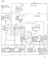
- each of electric power aggregators 3a-3c includes acquisition unit 10, priority order assignment unit 20, and control unit 30.
- constructions corresponding to an actual example to be described are shown as the constructions of each of acquisition unit 10, priority order assignment unit 20, and control unit 30.
- the constructions of each of acquisition unit 10, priority order assignment unit 20, and control unit 30 are not limited to those shown in FIG. 2 and can be modified as appropriate.
- Acquisition unit 10 is an example of the reception means.
- Acquisition unit 10 includes electric power demand request acquisition unit 11, connection detection unit 12, connection completion time acquisition unit 13, charging amount acquisition unit 14, and fixed charging speed acquisition unit 15.
- Acquisition unit 10 receives electric power demands from the electric power supply side.
- Priority order assignment unit 20 is one example of the assignment means.
- Priority order assignment unit 20 includes possible charging time calculation unit 21, index calculation unit 22, and priority order determination unit 23.
- Priority order assignment unit 20 assigns an order of priority relating to the charging of a plurality of EVs based on, for example, a predetermined index.
- Control unit 30 is an example of the control means.
- Control unit 30 includes setting unit 31 and charging control unit 32.
- Control unit 30 selects from among a plurality of EVs in the order of higher priority charging-object vehicles in which, for example, the ON/OFF setting for ON/OFF of charging is to be set to ON and sets the ON/OFF setting of the charging-object vehicles to ON.
- Control unit 30 then changes the number of charging-object vehicles according to changes of the electric power demands over time.
- Setting unit 31 includes requested demand ratio function calculation unit 31a, flattened charging speed calculation unit 31 b, normalization unit 31 c, correction coefficient calculation unit 31d, and target value setting unit 31e.
- electric power aggregators 3a-3c check the possible charging time, required charging amount, and the charging speed inherent to the EV for each of electric vehicles EV 5a-51 at the same time as the start of connection to chargers (power distribution network).
- electric power aggregators 3a-3c assign an order of priority relating to charging to each EV based on the possible charging time, the required charging amount, and the charging speed inherent to the EV.
- the time points may each be times at fixed time intervals or times that are set in advance. In the following explanation, each time point also refers to "each predetermined time.”
- Electric power aggregators 3a-3c select in order from EVs having the highest order of priority a number of EVs that satisfies the desired total electric power demand that is the target as the charging-object EVs (charging-object vehicles).
- Electric power aggregators 3a-3c set the ON setting of charging only for charging-object EVs.
- the charging speed when charging is ON is assumed to be set to a value that is inherent to each EV (charging speed that is inherent to the EV).
- electric power aggregators 3a-3c acquire the electric power demand requests that are data for prescribing the total electric power demand that is the target from the electric power supply (electric power company) side (for example, control server 2a) that, it is assumed, wishes to adjust the electric power demand.
- the electric power supply (electric power company) side for example, control server 2a
- the electric power demand requests include time sequence data that reflect the mid- to long-term electric power demand requests (for example, electric power prices that vary over time) and sudden electric power demand requests that occur due to accidents and short-term fluctuations in the output of renewable power sources.
- Electric power aggregators 3a-3c calculate the total electric power demand that is the target (the target value of charging demand) based on the time sequence data that reflect the mid-to long-term electric power demand requests and the sudden electric power demand requests.
- Electric power aggregators 3a-3c thus carry out charging scheduling, i.e., the determination of the charging ON/OFF state of each EV for each time point.
- Electric power aggregators 3a-3c control the storage batteries of electric vehicles EV 5a-51 and charging equipment based on the result of the charging scheduling.
- FIG. 3A is a view for describing an outline of the charging control method in the charging control system shown in FIG. 2 .
- Setting unit 31 first receives time sequence data relating to mid- and long-term electric power demand requests presented by the electric power supply (electric power company) side and the sudden electric power demand requests that immediately precede the charging presented from the electric power supply (electric power company) side. Setting unit 31 next defines (sets) the target value Ptotal_target(t) of the total charging demand at each time point based on the time sequence data relating to mid- to long-term electric power demand requests and the sudden electric power demand requests (Step A).
- time sequence data relating to the mid- to long-term electric power demand requests include, for example, electric power prices that change depending on time.
- the target value Ptotal_target(t) of the total charging demand includes advance scheduling as a portion that reverts to mid- to long-term electric power demand requests, and further, "real-time response" that reverts to sudden electric power demand requests.
- priority order assignment unit 20 receives the scheduled time of connection completion (departure) of each EV from acquisition unit 10 for each predetermined time point. Priority order assignment unit 20 next calculates the possible charging time Tn from the scheduled time of connection completion (departure) and a desired charging time margin. Priority order assignment unit 20 further receives from acquisition unit 10 at each predetermined time a charging amount (required charging amount) Qn that is required for each EV and a charging speed (inherent charging speed) pn that is inherent to each EV.
- priority order assignment unit 20 determines the priority of charging of EV based on the possible charging time Tn, the required charge amount Qn, and the inherent charging speed pn of each EV.
- n is the ID number of each EV.
- priority order assignment unit 20 calculates a required charging time Yn by dividing the required charging amount Qn by the inherent charging speed pn and then uses as the priority of charging index (POC) a value obtained by further dividing the required charging time Yn by the possible charging time Tn.
- priority order assignment unit 20 determines the charging order of priority of EV based on the priority of charging index (POC) and then shows the state of sorting the records of EV according to the determination result.
- Charging control unit 32 next selects charging-object EVs (charging-object vehicles) according to the order of priority until the total charging demand Ptotal(t) that is the total sum when the charging speed Pn(t) of each EV (i.e., the charging amount per unit time) is added in order from EVs having the highest priority most closely approaches the charging demand target value Ptotal_target(t).
- the total charging demand at each time point as seen from the electric power system network (electric power supply) side is the sum total Ptotal(t) for all EVs at each time point of this Pn(t).
- setting unit 31 preferably redefines the total charging demand target value Ptotal_target(t) in real time immediately after a real-time response.
- a system can be constructed as adjustment means that handles EV charging demands, whereby fluctuations in the output of a renewable power source can be absorbed.
- FIG. 3B also shows EVs for which the POC has attained a value equal to or greater than 1.
- An EV for which the POC has become equal to or greater than 1 corresponds to a case in which the possible charging time is already shorter than the required charging time at the time point at which the EV connected to the charging equipment (power distribution network). Because the charging speed and the scheduled departure time are fixed, the charging control side has no recourse but to raise the order of priority of charging and carry out charging as long as time permits. In this case, the desired charging amount at departure time obviously cannot be attained.
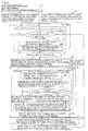
- FIG. 4 is a view for describing an actual example of the charging control method in the charging control system shown in FIG. 1 .
- Connection completion time acquisition unit 13 first acquires past performance data (for both workdays and holidays) relating to the charging equipment (power distribution network) connection times and charging amounts of each EV (Step 1).
- Connection completion time acquisition unit 13 next both estimates (for the following day until several days after for both workdays and holidays) the charging demand at each time point based on the past performance data and calculates the average value (estimated value) of the time points of arrival (connection to charging equipment) and departure (detachment from charging equipment) of EVs (Step 2).
- electric power demand request acquisition unit 11 acquires from the electric power supply side data of changes over time (including for example electric power prices) of the requested power demands that is to be the target of charge demand control. These data are the electric power demands requested from the electric power supply side and are subject to changes over time.
- FIG. 5 shows views for describing the process in requested demand ratio function calculation unit 31a.
- FIG. 5A shows the data acquired by electric power demand request acquisition unit 11.
- FIG. 5B shows requested demand ratio function F'(t) that is calculated in requested demand ratio function calculation unit 31a.
- Requested demand ratio function calculation unit 31a calculates the requested demand ratio function F'(t) that changes together with the passage of time as shown in FIG. 5B according to the electric power price that changes together with the passage of time as shown in FIG. 5A .
- This requested demand ratio function F'(t) is described here only because it is necessary when showing an example of the method of defining the target value Ptotal_target(t) of total charging demand, but when using another method of defining the target value of the total charging demand, there is no particular need to calculate this ratio function.
- connection detection unit 12 detects the connection of EVs to the charging equipment (power distribution network) (Step 4), and charging amount acquisition unit 14 acquires the current charged amount Zn and required charging amount Qn for each EV, and fixed charging speed acquisition unit 15 acquires the fixed charging speed pn that is inherent to each EV for each of these EV (Step 5).
- Possible charging time calculation unit 21 then, based on the scheduled (estimated) departure time that was calculated by connection completion time acquisition unit 13 and the current time, calculates the possible charging time Tn that is the guaranteed continuous time of connection to the charging equipment (power distribution network) that takes a margin into consideration (Step 6).
- the simulation shown here assumes that 50 EVs will be used in commuting (the EVs will be driving during the morning and evening).
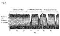
- FIG. 6 shows an example of the charging equipment connection pattern for 50 EVs.
- a random charging equipment (power distribution network) connection pattern (for a three-day interval of holiday/weekday/weekday) such as shown in FIG. 6 is generated for each EV and that the EVs are all connected to the charging equipment during the time intervals in which the EVs are not being driven, i.e., that all EVs are the objects of charging control, and the present embodiment is applied to this situation.
- Index calculation unit 22 next calculates a numerical POC that is the index of the priority of charging for each predetermined time point and creates a table (see FIG. 3B ) that consolidates these values for each predetermined time point (Step 7).
- Priority order determination unit 23 uses the priority of charging index POC to sort this table and determines the charging order of priority of EVs for each time point (Step 8).
- FIG. 4 shows an example in which [required charging amount On ⁇ fixed charging speed pn ⁇ possible charging time Tn] is taken as the index.
- Target value setting unit 31e sets the target value Ptotal_target(t) of the total charging demand that is to be the target.
- Normalization unit 31c first normalizes F'(t) such that the average value within a possible charging time slot is "1" for each EV, and then calculates the requested demand ratio function Fn(t) (Step 9).
- flattened charging speed calculation unit 31b calculates the flattened charging speed vn, i.e., the slowest charging speed that can still satisfy the desired charging amount at the departure time by dividing the required charging amount Qn by the possible charging time Tn for each EV (Step 10).
- correction coefficient calculation unit 31d When there is a sudden electric power demand request from the electric power supply side (Step 11), correction coefficient calculation unit 31d, according to the degree of the request, changes the real-time correction coefficient C(t) of the virtual charging speed to any value from "1" that was set as the initial value (Step 12).
- correction coefficient calculation unit 31d leaves the real-time correction coefficient C(t) of the virtual charging speed unchanged at "1" that was set as the initial value (Step 13).
- Target value setting unit 31e next multiplies the virtual flattened charging speed vn by the normalized requested demand ratio function Fn(t) and the real-time correction coefficient C(t) to calculate the virtual charging speed Vn(t) at each time point for each EV (Step 14).
- Target value setting unit 31e next defines (sets) the total sum of this virtual charging speed Vn(t) for all EVs as the target value Ptotal_target(t) of the total charging demand (Step 15).
- charging control unit 32 selects charging-object EVs (charging-object vehicles) in accordance with the order of priority until the total charging demand Ptotal(t), which is the sum total when the charging speeds Pn(t) of each EV (the charging amount per unit time) are added starting from EVs having higher order of priority, becomes closest to the charging demand target value Ptotal_target(t).
- charging control unit 32 determines the charging speed Pn(t) (pn or 0) at each time point for each EV (Step 16).
- Charging control unit 32 next communicates charging speed Pn(t) to each EV charging apparatus, whereby the control of the charging equipment, i.e., the electric power demand control, is finally realized (Step 17).
- FIG. 8 shows the results of simulating the changes in the form of total charging demand for a case that assumes 50 EVs. However, it is here assumed that there was no demand for real-time response and C(t) was made to equal "1" in all time slots.
- FIG. 8A shows, for reference, the result for a case in which charging scheduling is not carried out by the present exemplary embodiment, in other words, for a case in which each EV owner independently carried out charging scheduling such that charging cost was minimized based on electric power price data that change over time.
- the charging demand concentrates at specific times, although the results also depend on the form of the electric power price curve that is the starting point for decision-making. As a result, rather than absorbing fluctuations in the output of a renewable power source, these results indicate the potential for additionally incurring large and steep fluctuations in demand.
- FIG. 8B shows the result of the scheduling of charging of the present exemplary embodiment.
- the solid line that is depicted substantially edging the graph that indicates the electric power demand represents the target value Ptotal_target(t) of the total charging demand.
- charging scheduling is realized that substantially accurately reproduces the form of the requested demand ratio function F'(t) shown in FIG. 5B for each time slot.
- the function of controlling electric power demand of a multiple-EV linked charging system is sufficient to serve as the adjustment means for fluctuations in the output of a renewable power source.
- priority order assignment unit 20 resets the order of priority of EVs together with the passage of time. As a result, large disparities in the opportunities of charging for each EV can be reduced.
- the following methods of determining order can be considered. These methods may be used independently or may be used in combination. A combination of methods is effective when it is desired to determine priority for the same EV by yet another measure as the priority POC.
- the present exemplary embodiment allows circumvention at any time of the concentration of charging to limited EV or to parking areas of these EVs (the dispersal or minimization of load upon the internal storage batteries of EVs or upon the charging infrastructure). This is because, when a priority of charging index has been adopted in which priority of charging changes moment to moment, the charging load may be dispersed automatically.
- scheduling can be optimized by means of a low-load calculation process. This is because desired charging scheduling can be completed by using only a simple index to assign priority of charging to EV and without using a high-level mathematical method or optimization algorithm.
- the present exemplary embodiment is a charging control algorithm that is basically under no limitations due to the number of EVs.
- the total EV charging demand can be controlled even when the charging speed cannot be continuously adjusted from outside of the EVs. This is because the total EV charging demand is altered by implementing only the ON/OFF adjustment of the charging of each EV instead of through continuous adjustment of the charging speed.
- the certain attainment of desired (full) charging at the time of departure can be realized.
- change does not occur in the total charging amount ⁇ Qn in the initial scheduling when an EV connects to a charger despite the occurrence of any type of electric power demand request because the assumed flattened charging speed vn by which the certain attainment of desired charging is guaranteed when it is assumed that the charging speed can be continuously altered is multiplied by a requested demand ratio function F'(t) that has been normalized such that the average value within the time slot in which charging is possible is "1," and at the same time, even in the event of a real-time response to a sudden request for change in demand, this response is followed immediately by redefining the target value of total charging demand.
- G2V multiple-EV linked charging
- a program for realizing the functions of these components may be recorded on a recording medium that can be read in electric power aggregators 3a-3c, and electric power aggregators 3a-3c may then be caused to read and execute the program that was recorded on this recording medium.
- the recording medium that can be read in electric power aggregators 3a-3c refers to an IC card or memory card, a movable recording medium such as a floppy disk (registered trademark), a magneto-optical disk, a DVD, or a CD, or an HDD that is incorporated in electric power aggregators 3a-3c.
- the program that is recorded on this recording medium is, for example, read into control blocks, and processing similar to the processing described hereinabove is then carried out by the control of the control blocks.
Landscapes
- Engineering & Computer Science (AREA)
- Power Engineering (AREA)
- Transportation (AREA)
- Mechanical Engineering (AREA)
- Charge And Discharge Circuits For Batteries Or The Like (AREA)
- Electric Propulsion And Braking For Vehicles (AREA)
Abstract
Description
- The present invention relates to a charging control system, a charging control method, and a recording medium for motor vehicles that run on electricity including hybrid electric vehicles that are equipped with a storage battery together with another motive power source.
- As environmental problems becomes increasingly serious in recent years, renewable power sources such as solar cells and wind power generators that are rapidly being put into use are considered to be an effective means for achieving lower carbon emissions and solving the problem of energy resources. However, these types of renewable power sources experience large fluctuations in output. As a result, from the standpoint of electrical quality, an adjustment means is indispensable for offsetting the fluctuations in output of the renewable power sources. Thermal power generators, which feature rapid response speed, are currently the chief means used as such adjustment means. Thus, a dilemma may arise in which, as renewable electric power sources are increased, the number of thermal electric power generators that are not environmentally friendly need to be increased as adjustment means that adjusts large output fluctuations of the renewable electric power sources. Obtaining a powerful adjustment means to take the place of thermal power generators is therefore a major issue. As such an adjustment means, the introduction of high-capacity storage batteries (such as sodium sulfur batteries) is effective, but from the standpoint of installation and operating costs, the introduction of high-capacity storage batteries is considered to face extremely high obstacles.
- Great strides are being made in research relating to V2G (Vehicle-to-Grid) technology that, by effecting multiple linkage and operation, employs the storage batteries that are mounted in vehicles that run on electricity (hereinbelow referred to as EV (Electric Vehicles) that include hybrid electric vehicles that are equipped with storage batteries together with another motive power source) and that are expected to rapidly come into widespread use, similar to renewable power sources and the chargers to which these storage batteries are connected as virtual high-capacity storage batteries for electric power system stabilization. The V2G proposal itself dates to the 1980s, and research reports estimating the extent of the macro stabilization effect over an entire electric power system network have been issued continuously. In the past few years, the reports have come to focus on technology relating to real-time control, and moreover, micro control methods, i.e., individual charging and discharging of multiple EVs for the construction of an actual system.
- For example, Non-Patent
Document 1 describes a charging/discharging control method for implementing optimum scheduling by Particle Swarm Optimization (PSO), which is inspired by the movement of a school of fish, by setting EV operation models, distribution network models, and time-variation models of the price of electric power. -
Patent Document 1 describes the configuration of an EV charging planning device and refers to optimum charging scheduling that uses a genetic algorithm. - A case that assumes not only the charging of an EV but also the discharging from the EV to the distribution network (electric power system side) is typically referred to as V2G. However, a case that assumes only charging of an EV may be referred to as G2V to distinguish from V2G. G2V is assumed to decrease the load upon the internal storage batteries of an EV in proportion to the decrease of the number of charge/discharge cycles.
- Patent Document 1: Japanese Unexamined Patent Application Publication No.
2000-209707 - Non-Patent Document 1: G.K. Venayagamoorthy et al., "Real-Time Modeling of Distributed Plug-in Vehicles for V2G Transactions," Energy Conversion Congress and Exposition, 2009. ECCE 2009. IEEE, 3937-3941 (2009).
- As envisioned in the future, when a battery controller that is mounted in an EV is closed within the EV and independently controls the charging speed of the storage battery in the EV, it is highly likely that only controlling the charging ON/OFF will be possible from outside the EV and continuous adjustment of the charging speed will not be possible.
- The issue at hand is therefore the need for a charging control system that will facilitate the practical implementation of a multiple-EV linked charging system that can serve as an adjustment means that attends to the fluctuations in output of a renewable power source even for cases in which only the controlling the charging ON/OFF can be carried out from outside the EV and continuous adjustment of the charging speed cannot be implemented.
- It is an object of the present invention to provide a charging control system, charging control method, and program that can provide a solution to the above-described problem.
- A charging control system of the present invention for achieving the above-described object is a charging control system that controls charging of a plurality of vehicles that run on electric power and includes:
- assignment means that, based on a predetermined index, assigns to the plurality of vehicles an order of priority relating to charging;
- receiving means that receives electric power demands that are requested from the electric power supply side; and
- control means that selects from among the plurality of vehicles according to higher order of priority charging-object vehicles in which the ON/OFF setting for ON/OFF of the charging is to be set to ON, and that sets the ON/OFF setting of the charging-object vehicles to ON;
- wherein the control means changes the number of the charging-object vehicles according to changes of said electric power demands over time.
- A charging control method of the present invention is a charging control method in a charging control system that controls charging of a plurality of vehicles that run on electric power and includes:
- based on a predetermined index, assigning to the plurality of vehicles an order of priority relating to charging;
- receiving electric power demands that are requested from the electric power supply side; and
- selecting from among the plurality of vehicles in the order of higher order of priority charging-object vehicles in which the ON/OFF setting relating to the ON/OFF of the charging is to be set to ON and implementing control to set the ON/OFF setting of the charging-object vehicles to ON;
- wherein, in the control, the number of the charging-object vehicles changes according to changes of said electric power demands over time.
- A recording medium of the present invention is a recording medium that can be read by a computer and on which a program is recorded that causes a computer for controlling charging of a plurality of vehicles that run on electric power to execute:
- an assignment procedure of, based on a predetermined index, assigning an order of priority relating to charging of the plurality of vehicles;
- a reception procedure of receiving electric power demands that are requested from the electric power supply side; and
- a control procedure of selecting from among the plurality of vehicles in the order of higher order of priority charging-object vehicles in which the ON/OFF setting regarding the ON/OFF of the charging is to be set to ON and implementing control to set the ON/OFF setting of the charging-object vehicles to ON;
- wherein, in the control procedure, the number of the charging-object vehicles changes according to changes of said electric power demands over time.
- Due to the above-described configuration, the present invention can promote the practical implementation of a multiple-EV linked charging system that can serve as an adjustment means that attends to, for example, fluctuations in output of a renewable power source even in cases in which only the setting of ON/OFF of charging can be effected from outside the EVs and continuous adjustment of charging speed cannot be effected.
-
-
FIG. 1 shows the overall configuration of an example of the charging environment of electric vehicles in which the charging control system of the present invention has been adopted. -
FIG. 2 shows the configuration of the electric power aggregators shown inFIG. 1 . -
FIG. 3A is a view for describing the basic concept of the charging control method in the charging control system shown inFIG. 1 . -
FIG. 3B shows an example of an EV table. -
FIG. 4 is a view for describing an example of the charging control system shown inFIG. 1 . -
FIG. 5A shows data that are acquired in the electric power demand request acquisition unit. -
FIG. 5B shows requested demand ratio function F'(t) that is calculated in the requested demand ratio function calculation unit. -
FIG. 6 shows an example of the charger connection pattern of 50 EVs. -
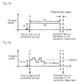
FIG. 7A shows a summary of the method of defining the target value of all charge demands. -
FIG. 7B shows a summary of the method of defining the target value of total charge demands. -
FIG. 8A shows the result of simulating changes in the form of total charging demands when the number of EVs is assumed to be 50. -
FIG. 8B shows the result of simulating changes in the form of total charge demands when the number of EVs is assumed to be 50. - An exemplary embodiment of the present invention is next described with reference to the accompanying drawings.
-
-
FIG. 1 shows an example of the charging environment of electric vehicles in which the charging control system of an exemplary embodiment of the present invention has been adopted. -
FIG. 2 shows the configuration ofelectric power aggregators 3a-3c shown inFIG. 1 . - As shown in
FIG. 1 , the present example is a system that allows charging ofelectric vehicles EV 5a-51 insmall community 7, inparking area 8, or at fast chargingstation 9.Electric power aggregators 3a-3c are provided corresponding to each ofsmall community 7,parking area 8, and fast chargingstation 9. Theseelectric power aggregators 3a-3c are connected tosubstation 2 by way of electric power distribution network andinformation communication network 1. Electricpower control server 2a is provided atsubstation 2. In addition, HEMS (Home Energy Management Systems) 4a-4d are provided insmall community 7. High-capacity energy storage 6 is also connected to electric power distribution network andinformation communication network 1. - As shown in
FIG. 2 , each ofelectric power aggregators 3a-3c includesacquisition unit 10, priorityorder assignment unit 20, andcontrol unit 30. InFIG. 2 , constructions corresponding to an actual example to be described are shown as the constructions of each ofacquisition unit 10, priorityorder assignment unit 20, andcontrol unit 30. The constructions of each ofacquisition unit 10, priorityorder assignment unit 20, andcontrol unit 30 are not limited to those shown inFIG. 2 and can be modified as appropriate. -
Acquisition unit 10 is an example of the reception means.Acquisition unit 10 includes electric power demandrequest acquisition unit 11,connection detection unit 12, connection completiontime acquisition unit 13, chargingamount acquisition unit 14, and fixed chargingspeed acquisition unit 15.Acquisition unit 10 receives electric power demands from the electric power supply side. - Priority
order assignment unit 20 is one example of the assignment means. Priorityorder assignment unit 20 includes possible chargingtime calculation unit 21,index calculation unit 22, and priorityorder determination unit 23. Priorityorder assignment unit 20 assigns an order of priority relating to the charging of a plurality of EVs based on, for example, a predetermined index. -
Control unit 30 is an example of the control means.Control unit 30 includes settingunit 31 and chargingcontrol unit 32.Control unit 30 selects from among a plurality of EVs in the order of higher priority charging-object vehicles in which, for example, the ON/OFF setting for ON/OFF of charging is to be set to ON and sets the ON/OFF setting of the charging-object vehicles to ON.Control unit 30 then changes the number of charging-object vehicles according to changes of the electric power demands over time. - Setting
unit 31 includes requested demand ratiofunction calculation unit 31a, flattened chargingspeed calculation unit 31 b,normalization unit 31 c, correction coefficient calculation unit 31d, and targetvalue setting unit 31e. - These constituent elements are actually assumed to be realized by a program that is installed in
electric power aggregators 3a-3c and are also assumed to be provided inHEMS 4a-4d. - In the charging control system that is configured as described hereinabove,
electric power aggregators 3a-3c check the possible charging time, required charging amount, and the charging speed inherent to the EV for each ofelectric vehicles EV 5a-51 at the same time as the start of connection to chargers (power distribution network). - At each time point,
electric power aggregators 3a-3c assign an order of priority relating to charging to each EV based on the possible charging time, the required charging amount, and the charging speed inherent to the EV. The time points may each be times at fixed time intervals or times that are set in advance. In the following explanation, each time point also refers to "each predetermined time." -
Electric power aggregators 3a-3c select in order from EVs having the highest order of priority a number of EVs that satisfies the desired total electric power demand that is the target as the charging-object EVs (charging-object vehicles). -
Electric power aggregators 3a-3c set the ON setting of charging only for charging-object EVs. - The charging speed when charging is ON is assumed to be set to a value that is inherent to each EV (charging speed that is inherent to the EV).
- In addition,
electric power aggregators 3a-3c acquire the electric power demand requests that are data for prescribing the total electric power demand that is the target from the electric power supply (electric power company) side (for example,control server 2a) that, it is assumed, wishes to adjust the electric power demand. - The electric power demand requests include time sequence data that reflect the mid- to long-term electric power demand requests (for example, electric power prices that vary over time) and sudden electric power demand requests that occur due to accidents and short-term fluctuations in the output of renewable power sources.
-
Electric power aggregators 3a-3c calculate the total electric power demand that is the target (the target value of charging demand) based on the time sequence data that reflect the mid-to long-term electric power demand requests and the sudden electric power demand requests. -
Electric power aggregators 3a-3c thus carry out charging scheduling, i.e., the determination of the charging ON/OFF state of each EV for each time point.Electric power aggregators 3a-3c control the storage batteries ofelectric vehicles EV 5a-51 and charging equipment based on the result of the charging scheduling. - The charging control method in the charging control system that is configured as described hereinabove is next described.
-
FIG. 3A is a view for describing an outline of the charging control method in the charging control system shown inFIG. 2 . - Setting
unit 31 first receives time sequence data relating to mid- and long-term electric power demand requests presented by the electric power supply (electric power company) side and the sudden electric power demand requests that immediately precede the charging presented from the electric power supply (electric power company) side. Settingunit 31 next defines (sets) the target value Ptotal_target(t) of the total charging demand at each time point based on the time sequence data relating to mid- to long-term electric power demand requests and the sudden electric power demand requests (Step A). - Here, time sequence data relating to the mid- to long-term electric power demand requests include, for example, electric power prices that change depending on time.
- The target value Ptotal_target(t) of the total charging demand includes advance scheduling as a portion that reverts to mid- to long-term electric power demand requests, and further, "real-time response" that reverts to sudden electric power demand requests.
- No particular limitations are imposed on the method of defining the target value Ptotal_target(t) of the total charging demand, but an example of this method will be described hereinbelow.
- When each EV next arrives at a parking area and connects to the charging equipment (distribution network), priority
order assignment unit 20 receives the scheduled time of connection completion (departure) of each EV fromacquisition unit 10 for each predetermined time point. Priorityorder assignment unit 20 next calculates the possible charging time Tn from the scheduled time of connection completion (departure) and a desired charging time margin. Priorityorder assignment unit 20 further receives fromacquisition unit 10 at each predetermined time a charging amount (required charging amount) Qn that is required for each EV and a charging speed (inherent charging speed) pn that is inherent to each EV. - At each time point, priority
order assignment unit 20 determines the priority of charging of EV based on the possible charging time Tn, the required charge amount Qn, and the inherent charging speed pn of each EV. - In this case, n is the ID number of each EV.
- No particular limitations apply to the definition of the index for determining the priority of charging. As one example, in
FIG. 3B , priorityorder assignment unit 20 calculates a required charging time Yn by dividing the required charging amount Qn by the inherent charging speed pn and then uses as the priority of charging index (POC) a value obtained by further dividing the required charging time Yn by the possible charging time Tn. InFIG. 3B , priorityorder assignment unit 20 determines the charging order of priority of EV based on the priority of charging index (POC) and then shows the state of sorting the records of EV according to the determination result. -
Charging control unit 32 next selects charging-object EVs (charging-object vehicles) according to the order of priority until the total charging demand Ptotal(t) that is the total sum when the charging speed Pn(t) of each EV (i.e., the charging amount per unit time) is added in order from EVs having the highest priority most closely approaches the charging demand target value Ptotal_target(t). -
Charging control unit 32 sets charging for charging-object EVs to ON, i.e., sets Pn(t) = pn, and sets charging for other EVs to OFF, i.e., sets Pn(t) = 0 (Step B). - The real-time electric power demand response as well as the scheduling of the charging speed Pn(t) (= pn or 0) at each time point in each EV is thus carried out by the above-described procedure.
- The total charging demand at each time point as seen from the electric power system network (electric power supply) side is the sum total Ptotal(t) for all EVs at each time point of this Pn(t).
- If charging is carried out at the charging demand target value Ptotal_target(t) without change after a real-time response, a change in the original total charge amount ΣQn can be expected to occur. In other words, the concern will arise that there will be EVs that have not reached the desired charging amount at the time of departure.
- Accordingly, in order to compensate for alterations to this total charge amount ΣQn, setting
unit 31 preferably redefines the total charging demand target value Ptotal_target(t) in real time immediately after a real-time response. - By using the above-described method, a system can be constructed as adjustment means that handles EV charging demands, whereby fluctuations in the output of a renewable power source can be absorbed.
-
FIG. 3B also shows EVs for which the POC has attained a value equal to or greater than 1. An EV for which the POC has become equal to or greater than 1 corresponds to a case in which the possible charging time is already shorter than the required charging time at the time point at which the EV connected to the charging equipment (power distribution network). Because the charging speed and the scheduled departure time are fixed, the charging control side has no recourse but to raise the order of priority of charging and carry out charging as long as time permits. In this case, the desired charging amount at departure time obviously cannot be attained. - Although explanation in the present exemplary embodiment has focused on a G2V system that controls only the charging of EV, by extending the scope such as by permitting the minus sign in the charging speed, the embodiment can also be applied to a typical V2G system that includes discharging from EVs.
- An actual example of the above-described charging control method is next described together with with the results of simulation.
-
FIG. 4 is a view for describing an actual example of the charging control method in the charging control system shown inFIG. 1 . - Connection completion
time acquisition unit 13 first acquires past performance data (for both workdays and holidays) relating to the charging equipment (power distribution network) connection times and charging amounts of each EV (Step 1). - Connection completion
time acquisition unit 13 next both estimates (for the following day until several days after for both workdays and holidays) the charging demand at each time point based on the past performance data and calculates the average value (estimated value) of the time points of arrival (connection to charging equipment) and departure (detachment from charging equipment) of EVs (Step 2). - In parallel with these procedures, electric power demand
request acquisition unit 11 acquires from the electric power supply side data of changes over time (including for example electric power prices) of the requested power demands that is to be the target of charge demand control. These data are the electric power demands requested from the electric power supply side and are subject to changes over time. - Requested demand ratio
function calculation unit 31a then calculates the requested demand ratio function F'(t) that changes over time based on these data (Step 3). However, at this point, normalization has not been carried out within the possible charging time of each EV, and this function is shared among all EVs. No particular limitations apply to the method of calculating this requested demand ratio function F'(t). In this example, the requested demand ratio function F'(t) is calculated as:
-
FIG. 5 shows views for describing the process in requested demand ratiofunction calculation unit 31a.FIG. 5A shows the data acquired by electric power demandrequest acquisition unit 11.FIG. 5B shows requested demand ratio function F'(t) that is calculated in requested demand ratiofunction calculation unit 31a. - Requested demand ratio
function calculation unit 31a calculates the requested demand ratio function F'(t) that changes together with the passage of time as shown inFIG. 5B according to the electric power price that changes together with the passage of time as shown inFIG. 5A . - This requested demand ratio function F'(t) is described here only because it is necessary when showing an example of the method of defining the target value Ptotal_target(t) of total charging demand, but when using another method of defining the target value of the total charging demand, there is no particular need to calculate this ratio function.
- After the above-described preparation,
connection detection unit 12 detects the connection of EVs to the charging equipment (power distribution network) (Step 4), and chargingamount acquisition unit 14 acquires the current charged amount Zn and required charging amount Qn for each EV, and fixed chargingspeed acquisition unit 15 acquires the fixed charging speed pn that is inherent to each EV for each of these EV (Step 5). - Possible charging
time calculation unit 21 then, based on the scheduled (estimated) departure time that was calculated by connection completiontime acquisition unit 13 and the current time, calculates the possible charging time Tn that is the guaranteed continuous time of connection to the charging equipment (power distribution network) that takes a margin into consideration (Step 6). The simulation shown here assumes that 50 EVs will be used in commuting (the EVs will be driving during the morning and evening). -
FIG. 6 shows an example of the charging equipment connection pattern for 50 EVs. - In the present exemplary embodiment, it is assumed that a random charging equipment (power distribution network) connection pattern (for a three-day interval of holiday/weekday/weekday) such as shown in
FIG. 6 is generated for each EV and that the EVs are all connected to the charging equipment during the time intervals in which the EVs are not being driven, i.e., that all EVs are the objects of charging control, and the present embodiment is applied to this situation. -
Index calculation unit 22 next calculates a numerical POC that is the index of the priority of charging for each predetermined time point and creates a table (seeFIG. 3B ) that consolidates these values for each predetermined time point (Step 7). - Priority
order determination unit 23 then uses the priority of charging index POC to sort this table and determines the charging order of priority of EVs for each time point (Step 8). - Although no particular limitations are imposed relating to priority of charging index POC as previously stated,
FIG. 4 shows an example in which [required charging amount On ÷ fixed charging speed pn ÷ possible charging time Tn] is taken as the index. - Target
value setting unit 31e then sets the target value Ptotal_target(t) of the total charging demand that is to be the target. - Although no particular limitation is imposed on the method of setting this target value of the total charging demand, an example was shown in the outline explanation of the method of defining the target value of the total charging demand in
FIGs. 7A and 7B and the flow chart ofFIG. 4 . -
Normalization unit 31c first normalizes F'(t) such that the average value within a possible charging time slot is "1" for each EV, and then calculates the requested demand ratio function Fn(t) (Step 9). - In addition, in a case in which it is assumed that the charging speed can change virtually continuously, flattened charging
speed calculation unit 31b calculates the flattened charging speed vn, i.e., the slowest charging speed that can still satisfy the desired charging amount at the departure time by dividing the required charging amount Qn by the possible charging time Tn for each EV (Step 10). - When there is a sudden electric power demand request from the electric power supply side (Step 11), correction coefficient calculation unit 31d, according to the degree of the request, changes the real-time correction coefficient C(t) of the virtual charging speed to any value from "1" that was set as the initial value (Step 12).
- On the other hand, when there is no sudden electric power demand request from the electric power supply side (Step 11), correction coefficient calculation unit 31d leaves the real-time correction coefficient C(t) of the virtual charging speed unchanged at "1" that was set as the initial value (Step 13).
- Target
value setting unit 31e next multiplies the virtual flattened charging speed vn by the normalized requested demand ratio function Fn(t) and the real-time correction coefficient C(t) to calculate the virtual charging speed Vn(t) at each time point for each EV (Step 14). - Target
value setting unit 31e next defines (sets) the total sum of this virtual charging speed Vn(t) for all EVs as the target value Ptotal_target(t) of the total charging demand (Step 15). - After the target value Ptotal_target(t) of the total charging demand has been defined by means of procedures such as those described above, charging
control unit 32 selects charging-object EVs (charging-object vehicles) in accordance with the order of priority until the total charging demand Ptotal(t), which is the sum total when the charging speeds Pn(t) of each EV (the charging amount per unit time) are added starting from EVs having higher order of priority, becomes closest to the charging demand target value Ptotal_target(t).Charging control unit 32 sets charging to ON, i.e., sets Pn(t) = pn for charging-object EVs and sets charging to OFF, i.e., sets Pn(t) = 0 for other EVs. By means of the above-described procedures, chargingcontrol unit 32 determines the charging speed Pn(t) (pn or 0) at each time point for each EV (Step 16). -
Charging control unit 32 next communicates charging speed Pn(t) to each EV charging apparatus, whereby the control of the charging equipment, i.e., the electric power demand control, is finally realized (Step 17). -
FIG. 8 shows the results of simulating the changes in the form of total charging demand for a case that assumes 50 EVs. However, it is here assumed that there was no demand for real-time response and C(t) was made to equal "1" in all time slots. -
FIG. 8A shows, for reference, the result for a case in which charging scheduling is not carried out by the present exemplary embodiment, in other words, for a case in which each EV owner independently carried out charging scheduling such that charging cost was minimized based on electric power price data that change over time. - In the case shown in
FIG. 8A , the charging demand concentrates at specific times, although the results also depend on the form of the electric power price curve that is the starting point for decision-making. As a result, rather than absorbing fluctuations in the output of a renewable power source, these results indicate the potential for additionally incurring large and steep fluctuations in demand. - In contrast,
FIG. 8B shows the result of the scheduling of charging of the present exemplary embodiment. InFIG. 8B , the solid line that is depicted substantially edging the graph that indicates the electric power demand represents the target value Ptotal_target(t) of the total charging demand. - In the example shown in
FIG. 8B , charging scheduling is realized that substantially accurately reproduces the form of the requested demand ratio function F'(t) shown inFIG. 5B for each time slot. As a result, in this case, the function of controlling electric power demand of a multiple-EV linked charging system is sufficient to serve as the adjustment means for fluctuations in the output of a renewable power source. - In the present exemplary embodiment, moreover, priority
order assignment unit 20 resets the order of priority of EVs together with the passage of time. As a result, large disparities in the opportunities of charging for each EV can be reduced. - Despite the apparent increase in the burden of charging costs borne by the owner of each EV resulting from the charging control realized by the present exemplary embodiment, in actuality, because it can be assumed that the present exemplary embodiment is used in a business model in which a value equivalent to the contribution to stabilization of the electric power system will be fed back from the electric power supply side by way of the operator of the multiple-EV linked charging system, the charging costs borne by each EV owner can be expected to decrease.
- Still further, changing the value of C(t) in real time from the initial value of "1" to any value enables a "real-time response" to sudden variations in electric power demands.
- However, if charging is simply continued based on the charging demand target value Ptotal_target(t) after a real-time response to electric power demands, a change can be expected to occur in the original total charging amount ΣQn. In other words, the concern will arise that there will be EVs that will not reach the desired charging amount at the time of departure. Accordingly, in order to compensate for the change in the total charging amount ΣQn immediately after a real-time response, redefinition (resetting) of the total charging demand target value Ptotal_target(t)
is preferably implemented in real time. In this way, the certain attainment of the desired charging amount at the departure time of the EV can be realized. - When the connection time of charging equipment is cut short at the convenience of an EV owner, the certain attainment of the desired charging at departure time is of course no longer possible. However, if a departure that is earlier than scheduled is reported to the charging control side as soon as possible, the order of priority can be raised by updating the possible charging time, whereby the possibility of attaining the desired charging at the time of departure can be increased.
- Finally, the explanation of the method for determining the order of priority of charging is supplemented hereinbelow.
- In addition to the method shown in the exemplary embodiment described above, the following methods of determining order can be considered. These methods may be used independently or may be used in combination. A combination of methods is effective when it is desired to determine priority for the same EV by yet another measure as the priority POC.
-
- (A) The method of determining the priority of charging may take as an index (POC) the load amount upon the charging means and equipment such as the charger itself, the cable that connects the EV and charger, and the connectors. This method is effective when, for example, the concern arises that the concentration of the charging demands may exceed the specified capacity of the above-described charging means and equipment and the charging demands must therefore be dispersed spatially or over time.
- (B) The method of determining priority of charging may take as an index (POC) the state of the storage battery, such as the amount of load upon the storage battery in the EV, the remaining life of the storage battery, and the storage rate (SOC). This is an effective method of determining priority when the protection or longer life of the storage battery in an EV are to be prioritized, carrying out early and fixed charging depending on the charging amount and charging rate (SOC) and avoiding a specific charging amount or charging rate (SOC) is effective in some cases.
- (C) The method of determining priority of charging may take as an index (POC) the local amount of load upon the electric power distribution network and equipment (electric power distribution lines) from the power plant up to arrival at the charger. As with method (A), the concern may arise that the specified capacity of common or shared electric power facilities will be exceeded by concentration of charging demand, and this method is effective when the charging demand must be dispersed spatially or over time.
- (D) The method of determining priority of charging may take as an index (POC) the contracted fee or the provisions of a contract guaranteeing service quality that has been concluded between the EV owner and the provider of charging control. This method prioritizes charging for specific EV users that takes as a basis a contract relating to service quality similar to, for example, a guarantee of bandwidth in the field of communication.
- (E) An index (POC) may be used that is based on any one of, or a combination of a plurality of: the charging amount of an EV, the charging rate of an EV, the permissible range of the charging amount of an EV, the permissible range of the charging speed of an EV, the desired charging amount that is necessary for an EV, the desired charging rate that is necessary for an EV, the permissible charging speed of an EV, the time necessary for desired charging in an EV, and the possible charging time of an EV. For example, an index (POC) may be used that is based on the value calculated by the formula: (desired charging amount, desired charging rate, or time necessary for desired charging) / (possible charging time).
- The effects of the present exemplary embodiment are next described.
- The present exemplary embodiment allows circumvention at any time of the concentration of charging to limited EV or to parking areas of these EVs (the dispersal or minimization of load upon the internal storage batteries of EVs or upon the charging infrastructure). This is because, when a priority of charging index has been adopted in which priority of charging changes moment to moment, the charging load may be dispersed automatically.
- In addition, real-time requests (requests to change demand) to the adjustment means can be dealt with. This is because the adoption of "(necessary charging time Yn) ÷ (possible charging time Tn)" as the priority of charging index automatically maximizes the degree of freedom for shifting charging times if the total EV charging demands are viewed as a whole by carrying out charging starting from EVs having little freedom for shifting of charging times, or alternatively, by postponing the charging of EVs having greater freedom for shifting of charging times. In addition, when determining the charging speed of each EV in real time, adaptability is improved by the exclusion of lengthy calculation procedures up to charger control by considering the mid- to long-term "advance scheduling" portion as independent through the separate introduction of a correction coefficient.
- In addition, scheduling can be optimized by means of a low-load calculation process. This is because desired charging scheduling can be completed by using only a simple index to assign priority of charging to EV and without using a high-level mathematical method or optimization algorithm.
- In addition, it is possible to ensure scalability for the number of EVs (to cope with a transitional period in which the number of EVs ranges from one to an increased number). This is because the present exemplary embodiment is a charging control algorithm that is basically under no limitations due to the number of EVs.
- In addition, the total EV charging demand can be controlled even when the charging speed cannot be continuously adjusted from outside of the EVs. This is because the total EV charging demand is altered by implementing only the ON/OFF adjustment of the charging of each EV instead of through continuous adjustment of the charging speed.
- In addition, due to the adoption of a method of defining (setting) the target value of the total charging demand that is described in the present exemplary embodiment, the following effects can be expected.
- The certain attainment of desired (full) charging at the time of departure can be realized. As one reason that can be offered for this effect, change does not occur in the total charging amount ΣQn in the initial scheduling when an EV connects to a charger despite the occurrence of any type of electric power demand request because the assumed flattened charging speed vn by which the certain attainment of desired charging is guaranteed when it is assumed that the charging speed can be continuously altered is multiplied by a requested demand ratio function F'(t) that has been normalized such that the average value within the time slot in which charging is possible is "1," and at the same time, even in the event of a real-time response to a sudden request for change in demand, this response is followed immediately by redefining the target value of total charging demand. However, cases are excluded in which the possible charging time is already shorter than the required charging time at the time point at which an EV connects to the charger (power distribution network). In such cases, the charging speed and the scheduled departure time are fixed, and the desired charging amount at the time of departure of course cannot be attained.
- The practical application of a multiple-EV linked charging (G2V) system that is capable of power adjustment for fluctuations in the output of renewable power sources can thus be further facilitated.
- In the present invention, instead of realizing the processing in
electric power aggregators 3a-3c by means of dedicated hardware, a program for realizing the functions of these components may be recorded on a recording medium that can be read inelectric power aggregators 3a-3c, andelectric power aggregators 3a-3c may then be caused to read and execute the program that was recorded on this recording medium. The recording medium that can be read inelectric power aggregators 3a-3c refers to an IC card or memory card, a movable recording medium such as a floppy disk (registered trademark), a magneto-optical disk, a DVD, or a CD, or an HDD that is incorporated inelectric power aggregators 3a-3c. The program that is recorded on this recording medium is, for example, read into control blocks, and processing similar to the processing described hereinabove is then carried out by the control of the control blocks. - Although the invention of the present application has been described with reference to exemplary embodiments, the invention of the present application is not limited to the above-described exemplary embodiments. The configuration and details of the invention of the present application are open to various modifications within the scope of the invention of the present application that will be understood by one of ordinary skill in the art.
- This application claims the benefits of priority based on Japanese Patent Application No.
2011-047838 -
- 1
- electric power distribution network and information communication network
- 2
- substation
- 2a
- electric power control server
- 3a-3c
- electric power aggregators
- 4a, 4b, 4c, 4d
- HEMS
- 5a-51
- electric vehicles EVs
- 6
- high-capacity energy storage
- 7
- small community
- 8
- parking area
- 9
- fast charging station
- 10
- acquisition unit
- 11
- electric power demand request acquisition unit
- 12
- connection detection unit
- 13
- connection completion time acquisition unit
- 14
- charging amount acquisition unit
- 15
- fixed charging speed acquisition unit
- 20
- priority order assignment unit
- 21
- possible charging time calculation unit
- 22
- index calculation unit
- 23
- priority order determination unit
- 30
- control unit
- 31
- setting unit
- 31a
- requested demand ratio function calculation unit
- 31b
- flattened charging speed calculation unit
- 31c
- normalization unit
- 31d
- correction coefficient calculation unit
- 32
- charging control unit
Claims (10)
- A charging control system that controls charging of a plurality of vehicles that run on electric power, comprising:assignment means that, based on a predetermined index, assigns to said plurality of vehicles an order of priority relating to charging;receiving means that receives electric power demands that are requested from an electric power supply side; andcontrol means that selects from among said plurality of vehicles according to higher said order of priority charging-object vehicles in which an ON/OFF setting for ON/OFF of said charging is to be set to ON and sets the ON/OFF setting of said charging-object vehicle to ON;wherein said control means changes the number of said charging-object vehicles according to changes of said electric power demands over time.
- The charging control system as set forth in claim 1, wherein said assignment means uses as said predetermined index an index that is based on any one of, or any plurality of: a charging amount of said vehicles, a charging rate of said vehicles, a permissible range of charging amount of said vehicles, a permissible range of charging rate of said vehicles, a desired charging amount that is necessary for said vehicles, a desired charging speed that is necessary for said vehicles, a permissible charging speed of said vehicles, a time interval required for said desired charging in said vehicles, and a time interval in which charging of said vehicles is possible.
- The charging control system as set forth in claim 2, wherein said assignment means uses as said predetermined index an index that is based on a value that is calculated by the formula: (said desired charging amount, said desired charging rate, or said time interval required for said desired charging) / (said time interval in which said charging is possible).
- The charging control system as set forth in claim 1, wherein:said control means controls charging means that is connected to said vehicle to control the ON/OFF of charging of that vehicle; andsaid assignment means uses as said predetermined index a load amount of said charging means or a load amount of electric power distribution lines that supply electric power to said charging means.
- The charging control system as set forth in claim 1, wherein said assignment means uses, as said predetermined index, a state of a storage battery that is installed in said vehicle and for which ON/OFF of said charging is controlled.
- The charging control system as set forth in claim 1, wherein said assignment means uses, as said predetermined index, a content of a contract concluded between an owner of said vehicle and a provider of charging control.
- The charging control system as set forth in any one of claims 1 to 6, wherein electric power demands requested from the electric power supply side include sudden electric power demands.
- The charging control system as set forth in any one of claims 1 to 6, wherein said control means calculates the charging amount per unit time of said plurality of vehicles based on a function that represents the change over time of electric power demands that are requested from the electric power supply side, uses the total sum of the charging amount to set a target value of charging demand, and changes the number of said charging-object vehicles according to said target value.
- A charging control method in a charging control system that controls charging of a plurality of vehicles that run on electric power, comprising:based on a predetermined index, assigning to said plurality of vehicles an order of priority relating to charging;receiving electric power demands that are requested from an electric power supply side; andselecting from among said plurality of vehicles according to higher said order of priority charging-object vehicles in which an ON/OFF setting relating to ON/OFF of said charging is to be set to ON and implementing control to set the ON/OFF setting of said charging-object vehicles to ON;wherein, in said control, the number of said charging-object vehicles changes according to changes of said electric power demands over time.
- A recording medium that can be read by a computer and on which a program is recorded that causes a computer for controlling charging of a plurality of vehicles that run on electric power to execute:an assignment procedure of, based on a predetermined index, assigning an order of priority relating to charging to said plurality of vehicles;a reception procedure of receiving electric power demands that are requested from an electric power supply side; anda control procedure of selecting from among said plurality of vehicles according to higher said order of priority charging-object vehicles in which an ON/OFF setting for ON/OFF of said charging is to be set to ON and implementing control to set the ON/OFF setting of said charging-object vehicles to ON;wherein, in said control procedure, the number of said charging-object vehicles changes according to changes of said electric power demands over time.
Applications Claiming Priority (2)
| Application Number | Priority Date | Filing Date | Title |
|---|---|---|---|
| JP2011047838 | 2011-03-04 | ||
| PCT/JP2012/053263 WO2012120976A1 (en) | 2011-03-04 | 2012-02-13 | Charging control system, charging control method and recording medium |
Publications (2)
| Publication Number | Publication Date |
|---|---|
| EP2683053A1 true EP2683053A1 (en) | 2014-01-08 |
| EP2683053A4 EP2683053A4 (en) | 2015-05-20 |
Family
ID=46797945
Family Applications (1)
| Application Number | Title | Priority Date | Filing Date |
|---|---|---|---|
| EP12754793.3A Withdrawn EP2683053A4 (en) | 2011-03-04 | 2012-02-13 | CHARGE CONTROL SYSTEM, CHARGE METHOD, AND RECORDING MEDIUM |
Country Status (4)
| Country | Link |
|---|---|
| US (1) | US9248752B2 (en) |
| EP (1) | EP2683053A4 (en) |
| JP (1) | JP6052621B2 (en) |
| WO (1) | WO2012120976A1 (en) |
Cited By (4)
| Publication number | Priority date | Publication date | Assignee | Title |
|---|---|---|---|---|
| CN106494246A (en) * | 2016-10-19 | 2017-03-15 | 宁波江东晶量电子科技有限公司 | Charging pile charge control system and method |
| EP3597474A1 (en) * | 2014-07-15 | 2020-01-22 | EnBW Energie Baden-Württemberg AG | Charging system comprising at least one charging station and method for operating a charging system for charging electric vehicles |
| CN113597720A (en) * | 2019-03-22 | 2021-11-02 | 日产自动车株式会社 | Power reception control method and power reception control device for power reception element |
| US11843271B2 (en) | 2019-03-22 | 2023-12-12 | Nissan Motor Co., Ltd. | Power reception control method for power storage element and power reception control device |
Families Citing this family (50)
| Publication number | Priority date | Publication date | Assignee | Title |
|---|---|---|---|---|
| CN103814394A (en) * | 2011-08-16 | 2014-05-21 | 佳境有限公司 | Estimation and management of loads in electric vehicle networks |
| JP2013055731A (en) * | 2011-09-01 | 2013-03-21 | Nissan Motor Co Ltd | Charging system and charging method |
| JP5919525B2 (en) * | 2011-11-22 | 2016-05-18 | パナソニックIpマネジメント株式会社 | Vehicle management system |
| US10192184B2 (en) * | 2012-03-30 | 2019-01-29 | Sony Corporation | Energy storage |
| KR101488586B1 (en) * | 2013-03-04 | 2015-02-02 | 주식회사 엘지씨엔에스 | Method and system of dynamic charging |
| US9511675B2 (en) * | 2013-09-13 | 2016-12-06 | Nissan North America, Inc. | Methods of decreasing peak energy consumption |
| JP6226193B2 (en) * | 2014-03-05 | 2017-11-08 | 清水建設株式会社 | Charge / discharge management device, charge / discharge management method, and program |
| JP6544720B2 (en) * | 2015-06-17 | 2019-07-17 | パナソニックIpマネジメント株式会社 | Management apparatus, management method, and management program |
| JP6724343B2 (en) | 2015-11-17 | 2020-07-15 | オムロン株式会社 | Reservation management device, reservation management system, and reservation management method |
| JP6597218B2 (en) | 2015-11-17 | 2019-10-30 | オムロン株式会社 | Battery reservation device and battery reservation method |
| JP6766343B2 (en) * | 2015-11-17 | 2020-10-14 | オムロン株式会社 | Battery reservation device |
| JP6582909B2 (en) | 2015-11-17 | 2019-10-02 | オムロン株式会社 | Battery reservation device and battery reservation method |
| SE541327C2 (en) * | 2016-03-01 | 2019-07-02 | Hybricon Bus Systems Ab | Systems and procedures for communication, prioritization, routing and charging of electric vehicles at charging stations with or without storage capacity |
| CN105654622B (en) * | 2016-03-04 | 2019-10-15 | 深圳市速满跑科技有限公司 | Charging pile management method and system |
| JP6585525B2 (en) * | 2016-03-08 | 2019-10-02 | 本田技研工業株式会社 | Power system |
| KR102285989B1 (en) * | 2016-07-27 | 2021-08-04 | 주식회사 케이티 | Apparatus and method for controlling battery charger for electric vehicle |
| US10468897B2 (en) * | 2016-10-14 | 2019-11-05 | International Business Machines Corporation | Wireless electric power sharing between vehicles |
| US20180175666A1 (en) * | 2016-12-20 | 2018-06-21 | Ecojiva, LLC | Electrical load management system |
| US12261432B2 (en) | 2016-12-20 | 2025-03-25 | Ecojiva Llc | Electrical load management system |
| JP6624084B2 (en) * | 2017-01-12 | 2019-12-25 | トヨタ自動車株式会社 | Electric vehicle |
| DE102017209716A1 (en) * | 2017-06-08 | 2018-12-13 | Audi Ag | Method for controlling a charging process of an energy storage device of a motor vehicle, control device, charging management device, server device, and motor vehicle |
| DE102017006678A1 (en) * | 2017-07-14 | 2019-01-17 | Drägerwerk AG & Co. KGaA | Cascadable multi-loader and method of operation thereof |
| JP6959063B2 (en) * | 2017-08-04 | 2021-11-02 | アズビル株式会社 | Charge control system |
| JP6879861B2 (en) * | 2017-08-08 | 2021-06-02 | アズビル株式会社 | Electric actuator |
| DE102018109077A1 (en) | 2018-04-17 | 2019-10-17 | Wobben Properties Gmbh | Charging station for charging electric vehicles |
| DE102018109078A1 (en) * | 2018-04-17 | 2019-10-17 | Wobben Properties Gmbh | Charging station for charging electric vehicles |
| JP7173674B2 (en) * | 2018-07-25 | 2022-11-16 | 東芝デジタルソリューションズ株式会社 | CHARGE CONTROL DEVICE, CHARGE MANAGEMENT SYSTEM, METHOD AND PROGRAM |
| JP7168293B2 (en) * | 2018-07-25 | 2022-11-09 | 東芝デジタルソリューションズ株式会社 | Charging management system, method and program |
| US10647218B1 (en) * | 2019-04-12 | 2020-05-12 | Bordin New Energy Vehicle Corporation, Inc. | System for thermally conditioning a battery pack of an electric vehicle |
| GB201907140D0 (en) * | 2019-05-21 | 2019-07-03 | Rolls Royce Plc | Forecast of electric vehicles state of charge and energy storage capacity |
| CN110601293A (en) * | 2019-09-18 | 2019-12-20 | 深圳来电科技有限公司 | Method and equipment for controlling charging of mobile power supply by mobile power supply leasing equipment |
| CN110525264B (en) * | 2019-09-22 | 2023-02-28 | 国网山东省电力公司莱芜供电公司 | A control system and control method for improving the operating reliability of parallel charging piles |
| JP7251503B2 (en) * | 2020-03-16 | 2023-04-04 | トヨタ自動車株式会社 | Power management device and power management method |
| CN112208377B (en) * | 2020-09-30 | 2022-03-15 | 重庆长安新能源汽车科技有限公司 | Household alternating current charging pile, system and charging method |
| JP7569703B2 (en) * | 2021-02-10 | 2024-10-18 | 日産自動車株式会社 | Method for controlling power receiving element and power receiving control device for power receiving element |
| DE102021103044A1 (en) | 2021-02-10 | 2022-08-11 | Audi Aktiengesellschaft | Method of exchanging electrical energy |
| CN113500940B (en) * | 2021-07-08 | 2022-06-28 | 东北电力大学 | A dynamic optimization strategy for orderly charging and discharging of electric vehicles based on particle swarm optimization |
| JP7619206B2 (en) * | 2021-08-17 | 2025-01-22 | トヨタ自動車株式会社 | Control device, program, and power management system |
| JP7563333B2 (en) * | 2021-08-20 | 2024-10-08 | トヨタ自動車株式会社 | Contactless power transmission system, vehicle, server and power transmission device |
| JP7739881B2 (en) * | 2021-09-13 | 2025-09-17 | 日産自動車株式会社 | Charging device, power system including the charging device, and charging method |
| FI131650B1 (en) * | 2022-06-17 | 2025-08-22 | Liikennevirta Oy / Virta Ltd | Method and device for managing charging transactions and charging station load |
| US20240034177A1 (en) * | 2022-07-20 | 2024-02-01 | Ford Global Technologies, Llc | Smart charge scheduling for an aggregate of electric vehicles considering grid demand |
| US12415436B2 (en) * | 2022-07-28 | 2025-09-16 | Rivian Ip Holdings, Llc | Non-wire alternatives grid deferrals |
| JP7673711B2 (en) * | 2022-08-10 | 2025-05-09 | トヨタ自動車株式会社 | Energy management method, program, and computer device |
| JP2024114506A (en) * | 2023-02-13 | 2024-08-23 | 株式会社東光高岳 | Information processing method, program, and information processing device |
| CN116667492B (en) * | 2023-06-06 | 2024-10-29 | 深圳三晖能源科技有限公司 | Charging control method and device based on Internet of Things, electronic device, and storage medium |
| CN119953225B (en) * | 2023-11-09 | 2025-10-31 | 重庆长安汽车股份有限公司 | An energy sharing and dispatching method, a charging method, a vehicle, and a server. |
| JP2025186831A (en) * | 2024-06-12 | 2025-12-24 | 株式会社日立製作所 | Charging system and charging method |
| JP7761111B1 (en) | 2024-10-09 | 2025-10-28 | 富士電機株式会社 | Control System |
| SE2550424A1 (en) * | 2025-05-05 | 2026-06-10 | Waybler Ab | A system and a Computer-Implemented Method for Charging Electric Vehicles |
Family Cites Families (9)
| Publication number | Priority date | Publication date | Assignee | Title |
|---|---|---|---|---|
| JP2000209707A (en) | 1999-01-07 | 2000-07-28 | Mitsubishi Electric Corp | Electric vehicle charging planning device |
| JP2001069678A (en) * | 1999-08-31 | 2001-03-16 | Seikichi Kobayashi | Charge control device for vehicles, etc. |
| JP2008067418A (en) * | 2006-09-04 | 2008-03-21 | Nippon Telegr & Teleph Corp <Ntt> | Charging control method, power storage device and charging control system |
| US8054048B2 (en) * | 2007-10-04 | 2011-11-08 | GM Global Technology Operations LLC | Power grid load management for plug-in vehicles |
| JP4333798B2 (en) | 2007-11-30 | 2009-09-16 | トヨタ自動車株式会社 | Charge control device and charge control method |
| AT506911B1 (en) * | 2008-06-05 | 2012-06-15 | Andexlinger Erich | METHOD AND SYSTEM FOR REGULATING THE INTENSITY OF LOADING A BATTERY |
| JP5077701B2 (en) | 2008-10-31 | 2012-11-21 | 本田技研工業株式会社 | Power supply control device |
| US8085034B2 (en) * | 2008-10-31 | 2011-12-27 | Yaniv Sirton | Managing charging of electric vehicles |
| JP4648464B2 (en) * | 2009-02-11 | 2011-03-09 | 中部電力株式会社 | Vehicle charging system and charging control device for apartment house |
-
2012
- 2012-02-13 WO PCT/JP2012/053263 patent/WO2012120976A1/en not_active Ceased
- 2012-02-13 US US14/002,678 patent/US9248752B2/en active Active
- 2012-02-13 EP EP12754793.3A patent/EP2683053A4/en not_active Withdrawn
- 2012-02-13 JP JP2013503432A patent/JP6052621B2/en active Active
Cited By (7)
| Publication number | Priority date | Publication date | Assignee | Title |
|---|---|---|---|---|
| EP3597474A1 (en) * | 2014-07-15 | 2020-01-22 | EnBW Energie Baden-Württemberg AG | Charging system comprising at least one charging station and method for operating a charging system for charging electric vehicles |
| CN106494246A (en) * | 2016-10-19 | 2017-03-15 | 宁波江东晶量电子科技有限公司 | Charging pile charge control system and method |
| CN106494246B (en) * | 2016-10-19 | 2019-01-25 | 广州乐盈信息科技股份有限公司 | Charging pile charging control system and method |
| CN113597720A (en) * | 2019-03-22 | 2021-11-02 | 日产自动车株式会社 | Power reception control method and power reception control device for power reception element |
| EP3944453A4 (en) * | 2019-03-22 | 2022-04-06 | Nissan Motor Co., Ltd. | ENERGY RECEIVING ELEMENTS ENERGY RECEIVING CONTROL METHOD AND ENERGY RECEIVING CONTROL DEVICE |
| US11390186B2 (en) | 2019-03-22 | 2022-07-19 | Nissan Motor Co., Ltd. | Power reception control method for power reception element and power reception control device |
| US11843271B2 (en) | 2019-03-22 | 2023-12-12 | Nissan Motor Co., Ltd. | Power reception control method for power storage element and power reception control device |
Also Published As
| Publication number | Publication date |
|---|---|
| JPWO2012120976A1 (en) | 2014-07-17 |
| US9248752B2 (en) | 2016-02-02 |
| WO2012120976A1 (en) | 2012-09-13 |
| US20130335032A1 (en) | 2013-12-19 |
| EP2683053A4 (en) | 2015-05-20 |
| JP6052621B2 (en) | 2016-12-27 |
Similar Documents
| Publication | Publication Date | Title |
|---|---|---|
| US9248752B2 (en) | Charging control system, charging control method, and recording medium | |
| US9278626B2 (en) | Charging control system, charging control method, and program | |
| Ma et al. | Optimal charging of plug-in electric vehicles for a car-park infrastructure | |
| Wang et al. | Integrated energy exchange scheduling for multimicrogrid system with electric vehicles | |
| Honarmand et al. | Optimal scheduling of electric vehicles in an intelligent parking lot considering vehicle-to-grid concept and battery condition | |
| JP6194795B2 (en) | Charge control device, battery management device, charge control method and program | |
| JP6473983B2 (en) | Power aggregator, charging method and program | |
| Bhatti et al. | Electric vehicle charging stations and the employed energy management schemes: a classification based comparative survey | |
| CN106130137A (en) | A kind of electric automobile coordinates charging system and self-decision method thereof | |
| He et al. | An optimal charging/discharging strategy for smart electrical car parks | |
| CN108321796A (en) | Household energy management system and method | |
| Darabi et al. | An event-based simulation framework to examine the response of power grid to the charging demand of plug-in hybrid electric vehicles | |
| US20230396064A1 (en) | Energy storage optimization | |
| Striani et al. | Wind based charging via autonomously controlled EV chargers under grid constraints | |
| Hussain et al. | Mobility-aware vehicle-to-grid (V2G) optimization for uniform utilization in smart grid based power distribution network | |
| Gunapriya et al. | Performance enhancement of EV charging stations and distribution system: a GJO–APCNN technique | |
| Wang et al. | Optimal joint management of charging and battery swapping services for electric vehicles | |
| Zhu et al. | A stochastic optimization approach to aggregated electric vehicles charging in smart grids | |
| Szcześniak et al. | Optimal electric bus charging scheduling for local balancing of fluctuations in PV generation | |
| Denagama Vitharanage | Optimal scheduling of electric vehicles in a low voltage distribution network for cost-efficient integration of distributed photovoltaic | |
| Elgammal et al. | Optimal electric vehicle charging control strategy powered by grid linked hybrid PV wind battery renewable energy system | |
| Shaaban et al. | PEVs real-time coordination in smart grid based on moving time window | |
| Popović et al. | Electric vehicles as electricity storages in electric power systems | |
| Sung et al. | Research on charging behavior of electric vehicles based on multiple objectives | |
| Abdelwahed et al. | Online optimization to enable sustainable public transport |
Legal Events
| Date | Code | Title | Description |
|---|---|---|---|
| PUAI | Public reference made under article 153(3) epc to a published international application that has entered the european phase |
Free format text: ORIGINAL CODE: 0009012 |
|
| 17P | Request for examination filed |
Effective date: 20130828 |
|
| AK | Designated contracting states |
Kind code of ref document: A1 Designated state(s): AL AT BE BG CH CY CZ DE DK EE ES FI FR GB GR HR HU IE IS IT LI LT LU LV MC MK MT NL NO PL PT RO RS SE SI SK SM TR |
|
| DAX | Request for extension of the european patent (deleted) | ||
| RA4 | Supplementary search report drawn up and despatched (corrected) |
Effective date: 20150417 |
|
| RIC1 | Information provided on ipc code assigned before grant |
Ipc: H02J 3/00 20060101ALI20150413BHEP Ipc: H02J 3/14 20060101ALI20150413BHEP Ipc: H01M 10/44 20060101ALI20150413BHEP Ipc: H02J 13/00 20060101ALI20150413BHEP Ipc: H02J 7/00 20060101ALI20150413BHEP Ipc: H02J 7/02 20060101AFI20150413BHEP Ipc: B60L 11/18 20060101ALI20150413BHEP |
|
| 17Q | First examination report despatched |
Effective date: 20160602 |
|
| STAA | Information on the status of an ep patent application or granted ep patent |
Free format text: STATUS: THE APPLICATION IS DEEMED TO BE WITHDRAWN |
|
| 18D | Application deemed to be withdrawn |
Effective date: 20170727 |