EP2682917A1 - State estimation device, state estimation method, and program - Google Patents
State estimation device, state estimation method, and program Download PDFInfo
- Publication number
- EP2682917A1 EP2682917A1 EP12751797.7A EP12751797A EP2682917A1 EP 2682917 A1 EP2682917 A1 EP 2682917A1 EP 12751797 A EP12751797 A EP 12751797A EP 2682917 A1 EP2682917 A1 EP 2682917A1
- Authority
- EP
- European Patent Office
- Prior art keywords
- driver
- group
- state
- identification
- result
- Prior art date
- Legal status (The legal status is an assumption and is not a legal conclusion. Google has not performed a legal analysis and makes no representation as to the accuracy of the status listed.)
- Withdrawn
Links
Images


Classifications
-
- G—PHYSICS
- G06—COMPUTING OR CALCULATING; COUNTING
- G06V—IMAGE OR VIDEO RECOGNITION OR UNDERSTANDING
- G06V20/00—Scenes; Scene-specific elements
- G06V20/50—Context or environment of the image
- G06V20/59—Context or environment of the image inside of a vehicle, e.g. relating to seat occupancy, driver state or inner lighting conditions
- G06V20/597—Recognising the driver's state or behaviour, e.g. attention or drowsiness
-
- G—PHYSICS
- G06—COMPUTING OR CALCULATING; COUNTING
- G06F—ELECTRIC DIGITAL DATA PROCESSING
- G06F18/00—Pattern recognition
- G06F18/20—Analysing
- G06F18/24—Classification techniques
- G06F18/243—Classification techniques relating to the number of classes
- G06F18/2431—Multiple classes
-
- G—PHYSICS
- G06—COMPUTING OR CALCULATING; COUNTING
- G06F—ELECTRIC DIGITAL DATA PROCESSING
- G06F18/00—Pattern recognition
- G06F18/20—Analysing
- G06F18/25—Fusion techniques
- G06F18/254—Fusion techniques of classification results, e.g. of results related to same input data
-
- G—PHYSICS
- G06—COMPUTING OR CALCULATING; COUNTING
- G06V—IMAGE OR VIDEO RECOGNITION OR UNDERSTANDING
- G06V10/00—Arrangements for image or video recognition or understanding
- G06V10/70—Arrangements for image or video recognition or understanding using pattern recognition or machine learning
- G06V10/764—Arrangements for image or video recognition or understanding using pattern recognition or machine learning using classification, e.g. of video objects
-
- G—PHYSICS
- G06—COMPUTING OR CALCULATING; COUNTING
- G06V—IMAGE OR VIDEO RECOGNITION OR UNDERSTANDING
- G06V10/00—Arrangements for image or video recognition or understanding
- G06V10/70—Arrangements for image or video recognition or understanding using pattern recognition or machine learning
- G06V10/77—Processing image or video features in feature spaces; using data integration or data reduction, e.g. principal component analysis [PCA] or independent component analysis [ICA] or self-organising maps [SOM]; Blind source separation
- G06V10/80—Fusion, i.e. combining data from various sources at the sensor level, preprocessing level, feature extraction level or classification level
- G06V10/809—Fusion, i.e. combining data from various sources at the sensor level, preprocessing level, feature extraction level or classification level of classification results, e.g. where the classifiers operate on the same input data
-
- G—PHYSICS
- G08—SIGNALLING
- G08B—SIGNALLING SYSTEMS, e.g. PERSONAL CALLING SYSTEMS; ORDER TELEGRAPHS; ALARM SYSTEMS
- G08B21/00—Alarms responsive to a single specified undesired or abnormal condition and not otherwise provided for
- G08B21/02—Alarms for ensuring the safety of persons
- G08B21/06—Alarms for ensuring the safety of persons indicating a condition of sleep, e.g. anti-dozing alarms
-
- G—PHYSICS
- G08—SIGNALLING
- G08G—TRAFFIC CONTROL SYSTEMS
- G08G1/00—Traffic control systems for road vehicles
- G08G1/16—Anti-collision systems
Definitions
- the present invention relates to a state estimation device, a state estimation method and a program, more specifically relating to a state estimation device to estimate the state of a driver, as well as a state estimation method and a program to estimate the state of a driver.
- the careless state can be roughly divided into a state in which the driver becomes inattentive to driving by his performing an act other than driving, such as carrying on a conversation and using a mobile phone and a state in which the driver decreases his attention due to fatigue and sleepiness.
- Patent Literatures 1 and 2 have been proposed for accurately detecting a drowsy of driver or a decrease in wakefulness of a driver, from the standpoint of safety (see, for example, Patent Literatures 1 and 2).
- An estimation device described in Patent Literature 1 estimates whether a driver is in a careless state in which the driver's attention has decreased, on the basis of output from an identification device in which input is biological information of the driver and information on the vehicle the driver drives. Specifically, the estimation device performs weighting on the basis of reliabilities of output results, and estimates, as the state of the driver, a result indicated by the majority of the output results from the identification device.
- a device described in Patent Literature 2 estimates the degree of sleepiness a driver feels on the basis of, for example, a plurality of feature amounts of information about the driver's eyes, such as time required for a blink and the degree of opening of the eyes.
- Patent Literature 1 estimates the state of a driver on the basis of output from the identification device. Therefore, the device determines only whether the driver is in a careless state or not, but has difficulty in estimating the state of the driver at multiple levels.
- the estimation device described in Patent Literature 2 is able to estimate the state of a driver at multiple levels.
- the state of the driver usually transitions continuously. Therefore, it is considered rare that a state in which wakefulness is high transitions to a state in which wakefulness is extremely low in a short period of time, or a state in which wakefulness is extremely low transitions to a state in which wakefulness is high in a short period of time. Accordingly, in order to accurately estimate the state of the driver, continuity of transition of the state needs to be taken into consideration.
- the present invention was made in view of the above circumstances, and has an objective of accurately estimating the state of a driver, taking it into consideration that the state of the driver continuously transitions.
- a state estimation device estimates the state of the driver, and includes:
- a state estimation method estimates the state of the driver, and includes:
- a program according to a third aspect of the present invention causes the computer to perform:
- an estimation result estimated on the basis of an identification result is verified. Accordingly, in performing verification, it is possible to accurately estimate the state of a driver by verifying, for example, continuity of transition of the state of the driver.
- FIG. 1 is a block diagram illustrating a schematic configuration of a state estimation system 10 according to the present embodiment.
- the state estimation system 10 estimates the state of a driver who drives a car on the basis of, for example, biological information of the driver. This estimates whether the driver is in a state to trigger a traffic accident due to sleepiness and/or fatigue.
- the state of a driver is specified such that a state in which the driver does not look sleepy at all is class 1, a state in which the driver looks a little sleepy is class 2, a state in which the driver looks sleepy is class 3, a state in which the driver looks quite sleepy is class 4, and a state in which the driver looks very sleepy is class 5 according to the definition by New Energy and Industrial Technology Development Organization (NEDO), and it is estimated to which class the state of the driver 60 belongs.
- NEDO New Energy and Industrial Technology Development Organization
- the state estimation system 10 has an imaging device 20 and an estimation device 30.
- the imaging device 20 photographs the face of the driver 60 sitting on a seat 61, converts an image obtained by photographing to an electric signal, and outputs the electric signal to the estimation device 30.
- the imaging device 20 is disposed on, for example, a steering wheel column, as illustrated in FIG. 2 .
- the view angle and posture of the imaging device 20 are adjusted so that the face of the driver 60 is positioned in the center of the field of view.
- the estimation device 30 has a feature amount outputter 31, identifiers 32a, 32b, an estimate value calculator 33, a state estimator 34, a verifier 35 and an estimation result outputter 36, as illustrated in FIG. 1 .
- the feature amount outputter 31 extracts biological information of the driver 60 as a feature amount from image information outputted from the imaging device 20, for example, every 10 seconds, and then outputs the extracted feature amount to the identifiers 32a, 32b. Specifically, the feature amount outputter 31 extracts biological information such as the degree a1 of opening of eyelids of the driver 60, the number a2 of blinks per unit time, the time a3 required from start of a blink to end of the blink, the direction a5 of the sight line, the orientation a5 of the face, on the basis of image information, and then sequentially outputs the extracted biological information a1 to a5 as feature amounts x N (a1, a2, a3, a4, a5).
- a feature amount x N (a1, a2, a3, a4, a5) is indicated by x N .
- N is an integer greater than or equal to 1.
- the present embodiment defines a first group composed of class 1, class 2 and class 3, a second group composed of class 4 and class 5, a third group composed of class 1, class 2, class 3 and class 4, and a fourth group composed of class 5.
- the state of the driver 60 is estimated on the basis of the result obtained in such a way that the identifiers 32a, 32b, which will be described later, identify a group to which the state of the driver 60 belongs.
- the identifier 32a identifies whether the state of the driver 60 belongs to the first group composed of class 1, class 2 and class 3, or the second group composed of class 4 and class 5.
- the identifier 32a outputs an identification result ⁇ N (x) to the estimate value calculator 33 if a feature amount x N is inputted.
- An AdaBoost-learned weak identifier for example, can be used as the identifier 32a.
- a sign of ⁇ N (x) indicates the group to which the state of the driver belongs. For example, if the sign of ⁇ N (x) is -, the state of the driver belongs to the first group; and if the sign of ⁇ N (x) is +, the state of the driver belongs to the second group.
- of ⁇ N (x) indicates the reliability of the identification result. For example, if the sign of ⁇ N (x) is -, a greater absolute value
- the identifier 32b identifies whether the state of the driver belongs to the third group composed of class 1, class 2, class 3 and class 4 or the fourth group composed of class 5.
- the identifier 32b outputs an identification result ⁇ N (x) to the estimate value calculator 33 if a feature amount x is inputted.
- an AdaBoost-learned weak identifier for example, can be used as the identifier 32b.
- a sign of ⁇ N (x) indicates the group to which the state of the driver belongs. For example, if the sign of ⁇ N (x) is -, the state of the driver belongs to the third group; and if the sign of ⁇ N (x) is +, the state of the driver belongs to the fourth group.
- of ⁇ N (x) indicates the reliability of the identification result. For example, if the sign of ⁇ N (x) is -, a greater absolute value
- the estimate value calculator 33 sequentially acquires an identification result ⁇ N (x) outputted from the identifier 32a, and then uses four identification results ⁇ N (x), ⁇ N-1 (x), ⁇ N-2 (x), ⁇ N-3 (x) including the latest identification result ⁇ N (x) to perform an operation represented by the following expression (1). This calculates an average value AVG ⁇ N of the four identification results ⁇ N (x), ⁇ N-1 (x), ⁇ N-2 (x), ⁇ N-3 (x) outputted from the identifier 32a.
- n is 4.
- the estimate value calculator 33 sequentially acquires an identification result ⁇ N (x) outputted from the identifier 32b, and then uses four identification results ⁇ N (x), ⁇ N-1 (x), ⁇ N-2 (x), ⁇ N-3 (x) including the latest identification result ⁇ N (x) to perform an operation represented by the following expression (2). This calculates an average value AVG ⁇ N of the four identification results ⁇ N (x), ⁇ N-1 (x), ⁇ N-2 (x), ⁇ N-3 (x) outputted from the identifier 32b.
- the estimate value calculator 33 performs operations represented by the following expressions (3) and (4) to calculate estimate values D34 N , D45 N .
- a sign(X) function contained in the above expressions (3) and (4) outputs 1 if the sign of X is +, outputs -1 if the sign of AVG ⁇ N is -, and outputs 0 if X is 0.
- Values of estimation results D34 N , D45 N represented by the above expression (1) is any one of 1, -1, 0, but in the present embodiment, it is rare that the variable of the sign function of the above expression (1) is 0. Accordingly, there is no problem in considering that values of estimation results D34 N , D45 N are either 1 or -1.
- the state estimator 34 estimates the state of the driver 60 on the basis of estimate values D34 N , D45 N and average values AVG ⁇ N , AVG ⁇ N .
- an identification result ⁇ N (x) if the sign thereof is -, the state of the driver 60 belongs to the first group, and if the sign thereof is +, the state of the driver 60 belongs to the second group. Accordingly, in an estimate value D34 N decided by the sign of an average value AVG ⁇ N of identification results ⁇ N (x), if the sign is -, the state of the driver 60 belongs to the first group, and if the sign is +, the state of the driver 60 belongs to the second group.
- an identification result ⁇ N (x) if the sign thereof is -, the state of the driver 60 belongs to the third group, and if the sign thereof is +, the state of the driver 60 belongs to the fourth group. Accordingly, in an estimate value D45 N decided by the sign of an average value AVG ⁇ N of identification results ⁇ N (x), if the sign thereof is -, the state of the driver 60 belongs to the third group, and if the sign thereof is +, the state of the driver 60 belongs to the fourth group.
- the estimate value D34 N is -1 and the estimate value D45 N is -1
- the state of the driver 60 belongs to the first and third groups.
- the first group is composed of classes 1 to 3 and the third group is composed of classes 1 to 4.
- the state estimator 34 estimates that if the estimate value D34 N is -1 and the estimate value D45 N is -1, the state of the driver 60 belongs to classes 1 to 3 that are common in the first and third groups.
- estimate value D34 N is -1 and the estimate value D45 N is 1, it is determined that the state of the driver 60 belongs to the first and fourth groups. However, as seen from FIG. 3 , there is no class common in the first and fourth groups.
- the state estimator 34 compares an absolute value
- the state estimator 34 estimates that the state of the driver 60 belongs to classes 1 to 3 that composes the first group, and if the absolute value
- the state of the driver 60 is determined to belong to the second and third groups.
- the second group is composed of classes 4 and 5 and the third group is composed of classes 1 to 4.
- the state estimator 34 estimates that if the estimate value D34 N is 1 and the estimate value D45 N is -1, the state of the driver 60 belongs to class 4 that is in common with the second and third groups.
- the state estimator 34 estimates that if the estimate value D34 N is 1 and the estimate value D45 N is 1, the state of the driver 60 belongs to class 5 that is in common with the second and fourth groups.
- the state estimator 34 performs the above estimation and outputs an estimation result RST N to the verifier 35.
- the verifier 35 verifies an estimation result RST N of the state estimator 34. Specifically, the verifier 35 first performs an operation represented by the following expression (5) to calculate a verification value CL N .
- the estimation result outptter 36 determines, if the verification value CL N outputted from the verifier 35 is -1, that the reliability of the estimation result RST N estimated by the state estimator 34 is low, and outputs the estimation result RST N-1 , which was estimated before estimation of the estimation result RST N , to an external device and/or the like.
- the estimation result outputter 36 compares the estimation result RST N estimated by the state estimator 34 and the estimation result RST N-1 estimated before estimation of the estimation result RST N . Then, if the estimation result outputter 36 determines that class to which the state of the driver 60 has transitioned continually, the estimation result outputter 36 outputs the estimation result RST N to an external device and/or the like. If as a result of comparison of the estimation result RST N and the estimation result RST N-1 the estimation result outputter 36 does not determine that class to which the state of the driver 60 belongs has transitioned continually, the estimation result outputter 36 outputs the estimation result RST N-1 to an external device and/or the like.
- the estimation result outputter 36 determines that the class to which the state of the driver 60 belongs has transitioned continually, and outputs the estimation result RST N to an external device and/or the like.
- the estimation result outputter 36 does not determine that the state of the driver 60 has not transitioned continually, and outputs the estimation result RST N-1 to an external device and/or the like.
- estimate values D34, D45 are calculated on the basis of an average value of a plurality of identification results ⁇ (x) and an average value of a plurality of identification results ⁇ (x). Then, on the basis of the estimate values D34, D45, the class to which the state of the driver 60 belongs is estimated. Therefore, when identification results ⁇ (x), ⁇ (x) are sequentially calculated, it is possible to accurately estimate the class to which the driver 60 belongs even if an identification result having much error is outputted.
- a verification value CL is calculated. Then, on the basis of the verification value CL, the estimation result RST is corrected. Specifically, if the reliability of the estimation result RST N is determined to be low on the basis of the verification value CL, the estimation result RST N-1 that was estimated the previous time is outputted as an estimation result RST. This allows for output of a highly reliable estimation result.
- the estimation result RST N and the estimation result RST N-1 are compared and if it is determined that class to which the driver 60 belongs has transitioned continually, the estimation result RST N is outputted. Meanwhile, the estimation result RST N and the estimation result RST N-1 are compared and if it is not determined that class to which the driver 60 belongs has transitioned continually, the previous estimation result RST N-1 is outputted. Therefore, a highly reliable estimation result is able to be outputted.
- a rapid change of the state of the driver is rare and at least 45 seconds is required from when the state of the driver has transitioned to a certain class until when the state of the driver transitions to the subsequent class. Therefore, like the present embodiment, if the class to which the state of the driver belongs is sequentially estimated on the basis of four identification results ⁇ N (x), ⁇ N-1 (x), ⁇ N-2 (x), ⁇ N-3 (x) and four identification results ⁇ N (x), ⁇ N-1 (x), ⁇ N-2 (x), ⁇ N-3 (x) sampled for forty seconds, the class to which the state of the driver is estimated to belong should transition continuously.
- the estimation result RST N-1 indicates that the state of the driver 60 belongs to classes 1 to 3
- a subsequent estimation result RST N is considered to indicate that the state of the driver 60 belongs to class 4 or that the state of the driver 60 belongs to classes 1 to 3.
- the estimation result RST N-1 indicates that the state of the driver 60 belongs to classes 1 to 3
- a subsequent estimation result RST N is unlikely to indicate the state of the driver 60 belongs to class 5. Therefore, by outputting only an estimation result that has continuity from the latest estimation result, a highly reliable estimation result is able to be outputted.
- a state estimation system 10 according to the present embodiment is different from the state estimation system 10 according to the first embodiment in that an estimation device 30 is realized by a common computer, microcomputer or the like.
- FIG. 4 is a block diagram illustrating physical configuration of the state estimation system 10. As illustrated in FIG. 4 , the state estimation system 10 includes the imaging device 20, and the estimation device 30 composed of a computer.
- the estimation device 30 includes a CPU (Central Processing Unit) 30a, a main storage 30b, an the auxiliary storage 30c, a display 30d, an input device 30e, an interface 30f and a system bus 30g that connects the above components to each other.
- a CPU Central Processing Unit
- the CPU 30a performs after-mentioned processing according to a program stored in the auxiliary storage 30c.
- the main storage 30b includes a RAM (Random Access Memory) and the like and is used as a work area of the CPU 30a.
- RAM Random Access Memory
- the auxiliary storage 30c includes a non-volatile memory such as a ROM (Read Only Memory), a magnetic disk and a semiconductor memory.
- the auxiliary storage 30c has stored a program to be executed by the CPU 30a and various parameters, and also sequentially stores image information outputted from the imaging device 20 and the result of processing by the CPU 30a.
- the display 30d includes, for example, an LCD (Liquid Crystal Display), and displays the result of processing by the CPU 30a.
- LCD Liquid Crystal Display
- the input device 30e includes input keys and a pointing device. An instruction from an operator is inputted via the input device 30e and is outputted via the system bus 30g to the CPU 30a.
- the interface 30f includes a serial interface, a LAN (Local Area Network) interface and/or the like.
- the imaging device 20 is connected via the interface 30f to the system bus 30g.
- the flow chart in FIG. 5 illustrates a series of processing algorithm of a program to be executed by the CPU 30a.
- processing to be performed by the estimation device 30 will be described with reference to FIG. 5 .
- This processing is performed by the CPU 30a after image information is outputted from the imaging device 20.
- the CPU 30a extracts biological information of the driver 60 as a feature amount x N from image information outputted from the imaging device 20, for example, every 10 seconds.
- the CPU 30a identifies whether the state of the driver 60 belongs to the first group composed of class 1, class 2 and class 3 or the second group composed of class 4 and class 5 on the basis of the feature amount x N , and then calculates an identification result ⁇ N (x).
- the CPU 30a identifies whether the state of the driver belongs to the third group composed of class 1, class 2, class 3 and class 4 or the fourth group composed of class 5 on the basis of the feature amount x N ., and then calculates an identification result ⁇ N (x).
- the CPU 30a uses four identification results ⁇ N (x), ⁇ N-1 (x), ⁇ N-2 (x), ⁇ N-3 (x) including the latest identification result ⁇ N (x) to perform an operation represented by the above expression (1), thereby calculating an average value AVG ⁇ N , and uses four identification results ⁇ N (x), ⁇ N-1 (x), ⁇ N-2 (x), ⁇ N-3 (x) including the latest identification result ⁇ N (x) to perform an operation represented by the above expression (2), thereby calculating an average value AVG ⁇ N .
- the CPU 30a performs operations represented by the above expressions (3) and (4) to calculate estimate values D34 N , D45 N .
- the CPU 30a performs processing illustrated in the flow chart in FIG. 6 for calculating an estimation result RST.
- step S201 the CPU 30a determines whether the estimate value D34 N is -1. If the estimate value D34 N is -1 (step S201: Yes), the CPU 30a proceeds to step S202.
- step S202 the CPU 30a determines whether the estimate value D45 N is -1. If the estimate value D45 N is -1 (step S202: Yes), the CPU 30a proceeds to step S203 and estimates that the state of the driver 60 belongs to any one of classes 1 to 3.
- step S202 if the estimate value D45 N is 1 (step S202: No), the CPU 30a proceeds to step S204.
- the CPU 30a compares the absolute value
- step S201 if the estimate value D34 N is 1 (step S201: No), the CPU 30a proceeds to step S207.
- step S207 the CPU 30a determines whether the estimate value D45 N is -1. If the estimate value D45 N is -1 (step S207: Yes), the CPU 30a proceeds to step S208 and estimates that the state of the driver 60 belongs to class 4. Meanwhile, if the estimate value D45 N is 1 (step S207: No), the CPU 30a proceeds to step S209 and estimates that the state of the driver 60 belongs to class 5.
- the CPU 30a verifies the estimation result RST. Specifically, the CPU 30a performs an operation represented by the following expression (5) to calculate a verification value CL N .
- the CPU 30a determines that the reliability of the estimation result RST N is low, and outputs the estimation result RST N-1 , estimated before estimation of the estimation result RST N , to an external device and/or the like.
- the CPU 30a compares the estimation result RST N and the estimation result RST N-1 estimated before estimation of the estimation result RST N . Then, if the CPU 30a determines that the class to which the state of the driver 60 belongs has transitioned continually, the CPU 30a outputs the estimation result RST N to an external device and/or the like. If the CPU 30a compares the estimation result RST N and the estimation result RST N-1 and does not determine that the class to which the state of the driver 60 belongs has transitioned continually, the CPU 301 outputs the previous estimation result RST N-1 to an external device and/or the like.
- estimate values D34, D45 are calculated on the basis of average values of a plurality of identification results ⁇ (x) and a plurality of identification results ⁇ (x). Then, the class to which the state of the driver 60 belongs is estimated on the basis of the estimate values D34, D45. Therefore, in sequential calculation of identification results ⁇ (x), ⁇ (x), even if an identification result having much error is outputted, the class to which the state of the driver 60 belongs is able to be accurately estimated.
- the estimation result RST is corrected on the basis of the verification value CL. Specifically, if it is determined that the reliability of the estimation result RST N is low on the basis of the verification value CL, the estimation result RST N-1 estimated the previous time is outputted as an estimation result RST. This allows for output of a highly reliable estimation result.
- the estimation result RST N and the estimation result RST N-1 are compared, and if it is determined that the class to which the state of the driver 60 belongs has transitioned continually, the estimation result RST N is outputted to an external device and/or the like. Meanwhile, the estimation result RST N and the estimation result RST N-1 are compared and if it is not determined that the class to which the state of the driver 60 has transitioned continually, the previous estimation result RST N-1 is outputted to an external device and/or the like. Therefore, a highly reliable estimation result is able to be outputted.
- Embodiments of the present invention have been described, but the present invention is not limited to the above embodiments.
- a case has been described in which a feature amount x N is outputted every 10 seconds.
- the present invention is not limited to this, but a feature amount x N may be outputted every 10 seconds or less.
- a feature amount is extracted from an image of the face of the driver 60.
- the present invention is not limited to this, but biological information, such as the pulse rate and breathing interval of the driver may be used as a feature amount.
- biological information such as the pulse rate and breathing interval of the driver may be used as a feature amount.
- an acceleration in a direction orthogonal to the travelling direction of a vehicle and/or the like may be used.
- a verification value CL is calculated on the basis of the expression (5).
- This expression (5) is one example, and a general expression for calculating a verification value CL is represented by, for example, the following expression (6).
- k is a constant.
- the estimation device 30 has two identifiers 32a, 32b.
- the present invention is not limited to this, but the estimation device 30 may include more than or equal to three identifiers.
- Function of the estimation device 30 according to each of the above embodiments is able to be realized by a dedicated hardware or a common computer system.
- a program stored in the auxiliary storage 30c of the estimation device 30 may be stored and distributed in a computer-readable recording medium such as a flexible disk, a CD-ROM (Compact Disk Read-Only Memory), a DVD (Digital Versatile Disk), a MO (Magneto-Optical disk), and by installing the program to a computer, a device to perform the above processing may be configured.
- a computer-readable recording medium such as a flexible disk, a CD-ROM (Compact Disk Read-Only Memory), a DVD (Digital Versatile Disk), a MO (Magneto-Optical disk)
- a program may be stored in a disk device or the like that a predetermined server device on a communication network such as the Internet has, and may be downloaded to a computer, for example, by being superimposed on a carrier wave.
- a program may be started and executed while being transferred via a communication network.
- All or part of a program may be executed on a server device, and the above image processing may be performed while information on the processing being transmitted and received via a communication network.
- part of the above function is realized by an OS (Operating System) or if the above function is realized by an OS and an application, only the part other than the OS may be stored and distributed in a medium and downloaded to a computer.
- OS Operating System
- a driver's state estimation device, a state estimation method and a program according to the present invention are suitable for estimating the state of the driver.
Landscapes
- Engineering & Computer Science (AREA)
- Theoretical Computer Science (AREA)
- Physics & Mathematics (AREA)
- General Physics & Mathematics (AREA)
- Computer Vision & Pattern Recognition (AREA)
- Evolutionary Computation (AREA)
- Artificial Intelligence (AREA)
- Data Mining & Analysis (AREA)
- Multimedia (AREA)
- Databases & Information Systems (AREA)
- Health & Medical Sciences (AREA)
- General Health & Medical Sciences (AREA)
- Medical Informatics (AREA)
- Software Systems (AREA)
- General Engineering & Computer Science (AREA)
- Evolutionary Biology (AREA)
- Computing Systems (AREA)
- Life Sciences & Earth Sciences (AREA)
- Bioinformatics & Cheminformatics (AREA)
- Bioinformatics & Computational Biology (AREA)
- Business, Economics & Management (AREA)
- Emergency Management (AREA)
- Traffic Control Systems (AREA)
Abstract
Description
- The present invention relates to a state estimation device, a state estimation method and a program, more specifically relating to a state estimation device to estimate the state of a driver, as well as a state estimation method and a program to estimate the state of a driver.
- Although the number of deaths resulting from traffic accidents has been decreasing recently, the number of traffic accidents still remains high. Traffic accidents are attributed to various causes, and one of the causes to trigger traffic accidents is that of a driver driving a vehicle in a careless state. The careless state can be roughly divided into a state in which the driver becomes inattentive to driving by his performing an act other than driving, such as carrying on a conversation and using a mobile phone and a state in which the driver decreases his attention due to fatigue and sleepiness.
- It is difficult for a driver himself/herself to prevent fatigue and sleepiness. Therefore, various systems have been proposed for accurately detecting a drowsy of driver or a decrease in wakefulness of a driver, from the standpoint of safety (see, for example,
Patent Literatures 1 and 2). - An estimation device described in
Patent Literature 1 estimates whether a driver is in a careless state in which the driver's attention has decreased, on the basis of output from an identification device in which input is biological information of the driver and information on the vehicle the driver drives. Specifically, the estimation device performs weighting on the basis of reliabilities of output results, and estimates, as the state of the driver, a result indicated by the majority of the output results from the identification device. - A device described in Patent Literature 2 estimates the degree of sleepiness a driver feels on the basis of, for example, a plurality of feature amounts of information about the driver's eyes, such as time required for a blink and the degree of opening of the eyes.
-
- PTL 1: Unexamined Japanese Patent Application Kokai Publication No.
2009-301367 - PTL 2: Unexamined Japanese Patent Application Kokai Publication No.
2009-90028 - The device described in
Patent Literature 1 estimates the state of a driver on the basis of output from the identification device. Therefore, the device determines only whether the driver is in a careless state or not, but has difficulty in estimating the state of the driver at multiple levels. - The estimation device described in Patent Literature 2 is able to estimate the state of a driver at multiple levels. However, the state of the driver usually transitions continuously. Therefore, it is considered rare that a state in which wakefulness is high transitions to a state in which wakefulness is extremely low in a short period of time, or a state in which wakefulness is extremely low transitions to a state in which wakefulness is high in a short period of time. Accordingly, in order to accurately estimate the state of the driver, continuity of transition of the state needs to be taken into consideration.
- The present invention was made in view of the above circumstances, and has an objective of accurately estimating the state of a driver, taking it into consideration that the state of the driver continuously transitions.
- In order to achieve the above objective, a state estimation device according to a first aspect of the present invention estimates the state of the driver, and includes:
- first identification means to identify, of a first group and a second group, the group to which the state of the driver belongs using a feature amount about the driver as an input value, each of the first group and the second group having a plurality of classes defined as based on a degree of the activity of the driver;
- second identification means to identify, of a third group and a fourth group, the group to which the state of the driver belongs using a feature amount about the driver as an input value, each of the third group and the fourth group having a plurality of classes defined as based on a degree of the activity of the driver;
- estimation means to estimate the class to which the state of the driver belongs, on the basis of the identification result of the first identification means and the identification result of the second identification means;
- verification means to verify an estimation result of the estimation means; and
- output means to output an estimation result that corresponds to a verification result of the verification means.
- In order to achieve the above objective, a state estimation method according to a second aspect of the present invention estimates the state of the driver, and includes:
- a first identification step to identify, of a first group and a second group, the group to which the state of the driver belongs using a feature amount about the driver as an input value, each of the first group and the second group having a plurality of classes defined as based on a degree of the activity of the driver;
- a second identification step to identify, of a third group and a fourth group, the group to which the state of the driver belongs using a feature amount about the driver as an input value, each of the third group and the fourth group having a plurality of classes defined as based on a degree of the activity of the driver;
- an estimation step to estimate the class to which the state of the driver belongs, on the basis of the identification result of the first identification step and the identification result of the second identification step;
- a verification step to verify the result of the estimation; and
- an output step to output an estimation result corresponding to the result of the verification.
- In order to achieve the above objective, a program according to a third aspect of the present invention causes the computer to perform:
- a first procedure to identify, of a first group and a second group, the group to which the state of the driver belongs using a feature amount about the driver as an input value, each of the first group and the second group having a plurality of classes defined as based on a degree of the activity of the driver;
- a second identification procedure to identify, of a third group and a fourth group, the group to which the state of the driver belongs using a feature amount about the driver as an input value, each of the third group and the fourth group having a plurality of classes defined as based on a degree of the activity of the driver;
- an estimation procedure to estimate the class to which the state of the driver belongs, on the basis of the identification result of the first identification procedure and the identification result of the second identification procedure;
- a verification procedure to verify the result of the estimation; and
- an output procedure to output an estimation result corresponding to the result of the verification.
- According to the present invention, an estimation result estimated on the basis of an identification result is verified. Accordingly, in performing verification, it is possible to accurately estimate the state of a driver by verifying, for example, continuity of transition of the state of the driver.
-
-
FIG. 1 is a block diagram illustrating a state estimation system according to a first embodiment; -
FIG. 2 is a diagram illustrating arrangement of an imaging device; -
FIG. 3 is a table for explaining classes that belong to each group; -
FIG. 4 is a block diagram illustrating a state estimation system according to a second embodiment; -
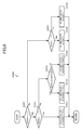
FIG. 5 is a flow chart for explaining operation of an estimation device; and -
FIG. 6 is a flow chart for explaining operation of an estimation device. - Hereinafter, a first embodiment of the present invention will be described with reference to drawings.
FIG. 1 is a block diagram illustrating a schematic configuration of astate estimation system 10 according to the present embodiment. Thestate estimation system 10 estimates the state of a driver who drives a car on the basis of, for example, biological information of the driver. This estimates whether the driver is in a state to trigger a traffic accident due to sleepiness and/or fatigue. - In the present embodiment, the state of a driver is specified such that a state in which the driver does not look sleepy at all is
class 1, a state in which the driver looks a little sleepy is class 2, a state in which the driver looks sleepy isclass 3, a state in which the driver looks quite sleepy isclass 4, and a state in which the driver looks very sleepy isclass 5 according to the definition by New Energy and Industrial Technology Development Organization (NEDO), and it is estimated to which class the state of thedriver 60 belongs. - As illustrated in
FIG. 1 , thestate estimation system 10 has animaging device 20 and anestimation device 30. - The
imaging device 20 photographs the face of thedriver 60 sitting on aseat 61, converts an image obtained by photographing to an electric signal, and outputs the electric signal to theestimation device 30. Theimaging device 20 is disposed on, for example, a steering wheel column, as illustrated inFIG. 2 . The view angle and posture of theimaging device 20 are adjusted so that the face of thedriver 60 is positioned in the center of the field of view. - The
estimation device 30 has afeature amount outputter 31,identifiers state estimator 34, averifier 35 and anestimation result outputter 36, as illustrated inFIG. 1 . - The feature amount outputter 31 extracts biological information of the
driver 60 as a feature amount from image information outputted from theimaging device 20, for example, every 10 seconds, and then outputs the extracted feature amount to theidentifiers driver 60, the number a2 of blinks per unit time, the time a3 required from start of a blink to end of the blink, the direction a5 of the sight line, the orientation a5 of the face, on the basis of image information, and then sequentially outputs the extracted biological information a1 to a5 as feature amounts xN(a1, a2, a3, a4, a5). This calculates the feature amounts x1(a1, a2, a3, a4, a5), x2(a1, a2, a3, a4, a5), ..., xN(a1, a2, a3, a4, a5) approximately every 10 seconds, which are outputted to theidentifiers - As illustrated in the table in
FIG. 3 , the present embodiment defines a first group composed ofclass 1, class 2 andclass 3, a second group composed ofclass 4 andclass 5, a third group composed ofclass 1, class 2,class 3 andclass 4, and a fourth group composed ofclass 5. The state of thedriver 60 is estimated on the basis of the result obtained in such a way that theidentifiers driver 60 belongs. - The
identifier 32a identifies whether the state of thedriver 60 belongs to the first group composed ofclass 1, class 2 andclass 3, or the second group composed ofclass 4 andclass 5. Theidentifier 32a outputs an identification result αN(x) to the estimate value calculator 33 if a feature amount xN is inputted. An AdaBoost-learned weak identifier, for example, can be used as theidentifier 32a. - In the identification result αN(x), a sign of αN(x) indicates the group to which the state of the driver belongs. For example, if the sign of αN(x) is -, the state of the driver belongs to the first group; and if the sign of αN(x) is +, the state of the driver belongs to the second group.
- In the identification result αN(x), a magnitude of absolute value |αN(x)| of αN(x) indicates the reliability of the identification result. For example, if the sign of αN(x) is -, a greater absolute value |αN(x)| means that the determination is more reliable that the state of the driver belongs to the first group; and if the sign of αN(x) is +, a greater absolute value |αN(x)| means that the determination is more reliable that the state of the driver belongs to the second group.
- The
identifier 32b identifies whether the state of the driver belongs to the third group composed ofclass 1, class 2,class 3 andclass 4 or the fourth group composed ofclass 5. Theidentifier 32b outputs an identification result βN(x) to the estimate value calculator 33 if a feature amount x is inputted. Similarly, an AdaBoost-learned weak identifier, for example, can be used as theidentifier 32b. - In the identification result βN(x), a sign of βN(x) indicates the group to which the state of the driver belongs. For example, if the sign of βN(x) is -, the state of the driver belongs to the third group; and if the sign of βN(x) is +, the state of the driver belongs to the fourth group.
- In the identification result βN(x), a magnitude of absolute value |βN(x)| of βN(x) indicates the reliability of the identification result. For example, if the sign of βN(x) is -, a greater absolute value |βN(x)| means that the determination is more reliable that the state of the driver belongs to the third group; and if the sign of βN(x) is +, a greater absolute value |βN(x)| means that the determination is more reliable that the state of the driver belongs to the fourth group.
- The estimate value calculator 33 sequentially acquires an identification result αN(x) outputted from the
identifier 32a, and then uses four identification results αN(x), αN-1(x), αN-2(x), αN-3(x) including the latest identification result αN(x) to perform an operation represented by the following expression (1). This calculates an average value AVGαN of the four identification results αN(x), αN-1(x), αN-2(x), αN-3(x) outputted from theidentifier 32a. Here, n is 4. - [Expression 1]

- Similarly, the estimate value calculator 33 sequentially acquires an identification result βN(x) outputted from the
identifier 32b, and then uses four identification results βN(x), βN-1(x), βN-2(x), βN-3(x) including the latest identification result βN(x) to perform an operation represented by the following expression (2). This calculates an average value AVGβN of the four identification results βN(x), βN-1(x), βN-2(x), βN-3(x) outputted from theidentifier 32b. - [Expression 2]

- Next, the estimate value calculator 33 performs operations represented by the following expressions (3) and (4) to calculate estimate values D34N, D45N.
- [Expression 3]

- [Expression 4]

- A sign(X) function contained in the above expressions (3) and (4)
outputs 1 if the sign of X is +, outputs -1 if the sign of AVGαN is -, andoutputs 0 if X is 0. Values of estimation results D34N, D45N represented by the above expression (1) is any one of 1, -1, 0, but in the present embodiment, it is rare that the variable of the sign function of the above expression (1) is 0. Accordingly, there is no problem in considering that values of estimation results D34N, D45N are either 1 or -1. - The
state estimator 34 estimates the state of thedriver 60 on the basis of estimate values D34N, D45N and average values AVGαN, AVGβN. - As described above, in an identification result αN(x), if the sign thereof is -, the state of the
driver 60 belongs to the first group, and if the sign thereof is +, the state of thedriver 60 belongs to the second group. Accordingly, in an estimate value D34N decided by the sign of an average value AVGαN of identification results αN(x), if the sign is -, the state of thedriver 60 belongs to the first group, and if the sign is +, the state of thedriver 60 belongs to the second group. - Similarly, in an identification result βN(x), if the sign thereof is -, the state of the
driver 60 belongs to the third group, and if the sign thereof is +, the state of thedriver 60 belongs to the fourth group. Accordingly, in an estimate value D45N decided by the sign of an average value AVGβN of identification results βN(x), if the sign thereof is -, the state of thedriver 60 belongs to the third group, and if the sign thereof is +, the state of thedriver 60 belongs to the fourth group. - Accordingly, when the estimate value D34N is -1 and the estimate value D45N is -1, it is determined that the state of the
driver 60 belongs to the first and third groups. As seen fromFIG. 3 , the first group is composed ofclasses 1 to 3 and the third group is composed ofclasses 1 to 4. Then, thestate estimator 34 estimates that if the estimate value D34N is -1 and the estimate value D45N is -1, the state of thedriver 60 belongs toclasses 1 to 3 that are common in the first and third groups. - If the estimate value D34N is -1 and the estimate value D45N is 1, it is determined that the state of the
driver 60 belongs to the first and fourth groups. However, as seen fromFIG. 3 , there is no class common in the first and fourth groups. - In this case, the
state estimator 34 compares an absolute value |AVGαN| of an average value AVGαN and an absolute value |AVGβN| of an average value AVGβN, and then estimates the group to which the state of thedriver 60 belongs on the basis of the estimate value D34N or D45N specified by the signs of average values AVGαN or AVGβN whose absolute value is greater. - For example, if the absolute value |AVGαN| of the average value AVGαN is greater than the absolute value |AVGβN| of the average value AVGβN, the
state estimator 34 estimates that the state of thedriver 60 belongs toclasses 1 to 3 that composes the first group, and if the absolute value |AVGβN| is greater than the absolute value |AVGαN|, thestate estimator 34 estimates that the state of thedriver 60 belongs toclass 5 that composes the fourth group. - If the estimate value D34N is 1 and the estimate value D45N is -1, the state of the
driver 60 is determined to belong to the second and third groups. As seen fromFIG. 3 , the second group is composed ofclasses classes 1 to 4. Then, thestate estimator 34 estimates that if the estimate value D34N is 1 and the estimate value D45N is -1, the state of thedriver 60 belongs toclass 4 that is in common with the second and third groups. - If the estimate value D34N is 1 and the estimate value D45N is 1, the state of the
driver 60 is determined to belong to the second and fourth groups. As seen fromFIG. 3 , the second group is composed ofclasses class 5. Then, thestate estimator 34 estimates that if the estimate value D34N is 1 and the estimate value D45N is 1, the state of thedriver 60 belongs toclass 5 that is in common with the second and fourth groups. - The
state estimator 34 performs the above estimation and outputs an estimation result RSTN to theverifier 35. - The
verifier 35 verifies an estimation result RSTN of thestate estimator 34. Specifically, theverifier 35 first performs an operation represented by the following expression (5) to calculate a verification value CLN. - [Expression 5]

- The estimation result outptter 36 determines, if the verification value CLN outputted from the
verifier 35 is -1, that the reliability of the estimation result RSTN estimated by thestate estimator 34 is low, and outputs the estimation result RSTN-1, which was estimated before estimation of the estimation result RSTN, to an external device and/or the like. - Meanwhile, if the verification value CLN is 1,the estimation result outputter 36 compares the estimation result RSTN estimated by the
state estimator 34 and the estimation result RSTN-1 estimated before estimation of the estimation result RSTN. Then, if the estimation result outputter 36 determines that class to which the state of thedriver 60 has transitioned continually, the estimation result outputter 36 outputs the estimation result RSTN to an external device and/or the like. If as a result of comparison of the estimation result RSTN and the estimation result RSTN-1 the estimation result outputter 36 does not determine that class to which the state of thedriver 60 belongs has transitioned continually, the estimation result outputter 36 outputs the estimation result RSTN-1 to an external device and/or the like. - Specifically, in the present embodiment, there are cases in which the state of the
driver 60 is estimated to belong toclasses 1 to 3,classes class 4, andclass 5, respectively. Then, for example if the estimation result RSTN-1 indicates that the state of thedriver 60 belongs toclasses 1 to 3and a subsequent estimation result RSTN indicates that the state of thedriver 60 belongs toclass 4 orclasses 1 to 3, the estimation result outputter 36 determines that the class to which the state of thedriver 60 belongs has transitioned continually, and outputs the estimation result RSTN to an external device and/or the like. - Meanwhile, for example, if the estimation result RSTN-1 indicates that the state of the
driver 60 belongs toclasses 1 to 3 and the subsequent estimation result RSTN indicates that the state of thedriver 60 belongs toclass 5, the estimation result outputter 36 does not determine that the state of thedriver 60 has not transitioned continually, and outputs the estimation result RSTN-1 to an external device and/or the like. - This enables an external device and/or the like to output to the
driver 60 an alarm for preventing drowsy driving and/or an announcement to urge thedriver 60 to take a rest, for example, on the basis of the estimation result. - As described above, in the present embodiment, estimate values D34, D45 are calculated on the basis of an average value of a plurality of identification results α(x) and an average value of a plurality of identification results β(x). Then, on the basis of the estimate values D34, D45, the class to which the state of the
driver 60 belongs is estimated. Therefore, when identification results α(x), β(x) are sequentially calculated, it is possible to accurately estimate the class to which thedriver 60 belongs even if an identification result having much error is outputted. - In the present embodiment, by performing an operation represented by the above expression (5), a verification value CL is calculated. Then, on the basis of the verification value CL, the estimation result RST is corrected. Specifically, if the reliability of the estimation result RSTN is determined to be low on the basis of the verification value CL, the estimation result RSTN-1 that was estimated the previous time is outputted as an estimation result RST. This allows for output of a highly reliable estimation result.
- In the present embodiment, the estimation result RSTN and the estimation result RSTN-1 are compared and if it is determined that class to which the
driver 60 belongs has transitioned continually, the estimation result RSTN is outputted. Meanwhile, the estimation result RSTN and the estimation result RSTN-1 are compared and if it is not determined that class to which thedriver 60 belongs has transitioned continually, the previous estimation result RSTN-1 is outputted. Therefore, a highly reliable estimation result is able to be outputted. - Specifically, it is considered that a rapid change of the state of the driver is rare and at least 45 seconds is required from when the state of the driver has transitioned to a certain class until when the state of the driver transitions to the subsequent class. Therefore, like the present embodiment, if the class to which the state of the driver belongs is sequentially estimated on the basis of four identification results αN(x), αN-1(x), αN-2(x), αN-3(x) and four identification results βN(x), βN-1(x), βN-2(x), βN-3(x) sampled for forty seconds, the class to which the state of the driver is estimated to belong should transition continuously.
- For example, if the estimation result RSTN-1 indicates that the state of the
driver 60 belongs toclasses 1 to 3, a subsequent estimation result RSTN is considered to indicate that the state of thedriver 60 belongs toclass 4 or that the state of thedriver 60 belongs toclasses 1 to 3. Meanwhile, if the estimation result RSTN-1 indicates that the state of thedriver 60 belongs toclasses 1 to 3, a subsequent estimation result RSTN is unlikely to indicate the state of thedriver 60 belongs toclass 5. Therefore, by outputting only an estimation result that has continuity from the latest estimation result, a highly reliable estimation result is able to be outputted. - Next, a second embodiment of the present invention will be described with reference to drawings. The same or equivalent configurations as those of the first embodiment have the same reference signs and description of those reference signs will be omitted or simplified.
- A
state estimation system 10 according to the present embodiment is different from thestate estimation system 10 according to the first embodiment in that anestimation device 30 is realized by a common computer, microcomputer or the like. -
FIG. 4 is a block diagram illustrating physical configuration of thestate estimation system 10. As illustrated inFIG. 4 , thestate estimation system 10 includes theimaging device 20, and theestimation device 30 composed of a computer. - The
estimation device 30 includes a CPU (Central Processing Unit) 30a, amain storage 30b, an theauxiliary storage 30c, adisplay 30d, aninput device 30e, aninterface 30f and asystem bus 30g that connects the above components to each other. - The
CPU 30a performs after-mentioned processing according to a program stored in theauxiliary storage 30c. - The
main storage 30b includes a RAM (Random Access Memory) and the like and is used as a work area of theCPU 30a. - The
auxiliary storage 30c includes a non-volatile memory such as a ROM (Read Only Memory), a magnetic disk and a semiconductor memory. Theauxiliary storage 30c has stored a program to be executed by theCPU 30a and various parameters, and also sequentially stores image information outputted from theimaging device 20 and the result of processing by theCPU 30a. - The
display 30d includes, for example, an LCD (Liquid Crystal Display), and displays the result of processing by theCPU 30a. - The
input device 30e includes input keys and a pointing device. An instruction from an operator is inputted via theinput device 30e and is outputted via thesystem bus 30g to theCPU 30a. - The
interface 30f includes a serial interface, a LAN (Local Area Network) interface and/or the like. Theimaging device 20 is connected via theinterface 30f to thesystem bus 30g. - The flow chart in
FIG. 5 illustrates a series of processing algorithm of a program to be executed by theCPU 30a. Hereinafter, processing to be performed by theestimation device 30 will be described with reference toFIG. 5 . This processing is performed by theCPU 30a after image information is outputted from theimaging device 20. - At step S 101, the
CPU 30a extracts biological information of thedriver 60 as a feature amount xN from image information outputted from theimaging device 20, for example, every 10 seconds. - At the subsequent step S 102, the
CPU 30a identifies whether the state of thedriver 60 belongs to the first group composed ofclass 1, class 2 andclass 3 or the second group composed ofclass 4 andclass 5 on the basis of the feature amount xN, and then calculates an identification result αN(x). - Similarly, the
CPU 30a identifies whether the state of the driver belongs to the third group composed ofclass 1, class 2,class 3 andclass 4 or the fourth group composed ofclass 5 on the basis of the feature amount xN., and then calculates an identification result βN(x). - At the subsequent step S103, the
CPU 30a uses four identification results αN(x), αN-1(x), αN-2(x), αN-3(x) including the latest identification result αN(x) to perform an operation represented by the above expression (1), thereby calculating an average value AVGαN, and uses four identification results βN(x), βN-1(x), βN-2(x), βN-3(x) including the latest identification result βN(x) to perform an operation represented by the above expression (2), thereby calculating an average value AVGβN. - At the subsequent step S 104, the
CPU 30a performs operations represented by the above expressions (3) and (4) to calculate estimate values D34N, D45N. - At the subsequent step S 105, the
CPU 30a performs processing illustrated in the flow chart inFIG. 6 for calculating an estimation result RST. - At the first step S201, the
CPU 30a determines whether the estimate value D34N is -1. If the estimate value D34N is -1 (step S201: Yes), theCPU 30a proceeds to step S202. - At step S202, the
CPU 30a determines whether the estimate value D45N is -1. If the estimate value D45N is -1 (step S202: Yes), theCPU 30a proceeds to step S203 and estimates that the state of thedriver 60 belongs to any one ofclasses 1 to 3. - At step S202, if the estimate value D45N is 1 (step S202: No), the
CPU 30a proceeds to step S204. - At the subsequent step S204, the
CPU 30a compares the absolute value |AVGαN| of the average value AVGαN and the absolute value |AVGβN| of the average value AVGβN. If theCPU 30a determines that the absolute value |AVGαN| is greater (step S204: Yes), theCPU 30a proceeds to step S205 and estimates that the state of thedriver 60 belongs to any one ofclasses 1 to 3. Meanwhile, if the CPU30a determines that the absolute value |AVGαN| is smaller (step S204: No), theCPU 30a proceeds to step S206 and estimates that the state of thedriver 60 belongs to any one ofclasses - At step S201, if the estimate value D34N is 1 (step S201: No), the
CPU 30a proceeds to step S207. - At step S207, the
CPU 30a determines whether the estimate value D45N is -1. If the estimate value D45N is -1 (step S207: Yes), theCPU 30a proceeds to step S208 and estimates that the state of thedriver 60 belongs toclass 4. Meanwhile, if the estimate value D45N is 1 (step S207: No), theCPU 30a proceeds to step S209 and estimates that the state of thedriver 60 belongs toclass 5. - When processing at steps S203, S205, S206, S208 and S209 are completed, the
CPU 30a proceeds to step S106. - At the subsequent step S 106, the
CPU 30a verifies the estimation result RST. Specifically, theCPU 30a performs an operation represented by the following expression (5) to calculate a verification value CLN. - At the subsequent step S107, if the verification value CLN is -1, the
CPU 30a determines that the reliability of the estimation result RSTN is low, and outputs the estimation result RSTN-1, estimated before estimation of the estimation result RSTN, to an external device and/or the like. - Meanwhile, if the verification value CLN is 1, the
CPU 30a compares the estimation result RSTN and the estimation result RSTN-1 estimated before estimation of the estimation result RSTN. Then, if theCPU 30a determines that the class to which the state of thedriver 60 belongs has transitioned continually, theCPU 30a outputs the estimation result RSTN to an external device and/or the like. If theCPU 30a compares the estimation result RSTN and the estimation result RSTN-1 and does not determine that the class to which the state of thedriver 60 belongs has transitioned continually, the CPU 301 outputs the previous estimation result RSTN-1 to an external device and/or the like. - As described above, in the present embodiment, estimate values D34, D45 are calculated on the basis of average values of a plurality of identification results α(x) and a plurality of identification results β(x). Then, the class to which the state of the
driver 60 belongs is estimated on the basis of the estimate values D34, D45. Therefore, in sequential calculation of identification results α(x), β(x), even if an identification result having much error is outputted, the class to which the state of thedriver 60 belongs is able to be accurately estimated. - In the present embodiment, by performing an operation represented by the above expression (5), a verification value CL is calculated. Then, the estimation result RST is corrected on the basis of the verification value CL. Specifically, if it is determined that the reliability of the estimation result RSTN is low on the basis of the verification value CL, the estimation result RSTN-1 estimated the previous time is outputted as an estimation result RST. This allows for output of a highly reliable estimation result.
- In the present embodiment, the estimation result RSTN and the estimation result RSTN-1 are compared, and if it is determined that the class to which the state of the
driver 60 belongs has transitioned continually, the estimation result RSTN is outputted to an external device and/or the like. Meanwhile, the estimation result RSTN and the estimation result RSTN-1 are compared and if it is not determined that the class to which the state of thedriver 60 has transitioned continually, the previous estimation result RSTN-1 is outputted to an external device and/or the like. Therefore, a highly reliable estimation result is able to be outputted. - Embodiments of the present invention have been described, but the present invention is not limited to the above embodiments. For example, in the above embodiments, a case has been described in which a feature amount xN is outputted every 10 seconds. The present invention is not limited to this, but a feature amount xN may be outputted every 10 seconds or less.
- In the above embodiments, a case has been described in which a feature amount is extracted from an image of the face of the
driver 60. The present invention is not limited to this, but biological information, such as the pulse rate and breathing interval of the driver may be used as a feature amount. As a feature amount, an acceleration in a direction orthogonal to the travelling direction of a vehicle and/or the like may be used. - In the above embodiments, a verification value CL is calculated on the basis of the expression (5). This expression (5) is one example, and a general expression for calculating a verification value CL is represented by, for example, the following expression (6). k is a constant.
- Expression 6]

- In the above embodiments, a case has been described in which the
estimation device 30 has twoidentifiers estimation device 30 may include more than or equal to three identifiers. - Function of the
estimation device 30 according to each of the above embodiments is able to be realized by a dedicated hardware or a common computer system. - In the second embodiment, a program stored in the
auxiliary storage 30c of theestimation device 30 may be stored and distributed in a computer-readable recording medium such as a flexible disk, a CD-ROM (Compact Disk Read-Only Memory), a DVD (Digital Versatile Disk), a MO (Magneto-Optical disk), and by installing the program to a computer, a device to perform the above processing may be configured. - A program may be stored in a disk device or the like that a predetermined server device on a communication network such as the Internet has, and may be downloaded to a computer, for example, by being superimposed on a carrier wave.
- A program may be started and executed while being transferred via a communication network.
- All or part of a program may be executed on a server device, and the above image processing may be performed while information on the processing being transmitted and received via a communication network.
- If part of the above function is realized by an OS (Operating System) or if the above function is realized by an OS and an application, only the part other than the OS may be stored and distributed in a medium and downloaded to a computer.
- Various embodiments and variations of the present invention are possible without departing from the extensive spirit and scope of the present invention. The above embodiments are for explaining the present invention, not for limiting the scope of the present invention.
- This application is based on Japanese Patent Application No.
2011-47028 filed on March 3, 2011 2011-47028 - A driver's state estimation device, a state estimation method and a program according to the present invention are suitable for estimating the state of the driver.
-
- 10
- State estimation system
- 20
- Imaging device
- 30
- Estimation device
- 30a
- CPU
- 30b
- Main storage
- 30c
- Auxiliary storage
- 30d
- Display
- 30e
- Input device
- 30f
- Interface
- 30g
- System bus
- 31
- Feature amount outputter
- 32a
- Identifier
- 32b
- Identifier
- 33
- Estimate value calculator
- 34
- State estimator
- 35
- Verifier
- 36
- Estimation result outputter
- 60
- Driver
- 61
- Seat
- α, β
- Identification results
- D34, D45N
- Estimation results
- RST
- Estimation result
Claims (8)
- A state estimation device to estimate the state of a driver, the state estimation device comprising:first identification means to identify, of a first group and a second group, the group the state of the driver belongs to using a feature amount about the driver as an input value, each of the first group and the second group having a plurality of classes defined as based on a degree of the activity of the driversecond identification means to identify, of a third group and a forth group, the group the state of the driver belongs to using a feature amount about the driver as an input value, each of the first group and the second group having a plurality of classes defined as based on a degree of the activity of the driverestimation means to estimate the class to which the state of the driver belongs on the basis of the identification result of the first identification means and the identification result of the second identification means;verification means to verify an estimation result of the estimation means;
andoutput means to output an estimation result that corresponds to a verification result of the verification means. - The state estimation device according to Claim 1, wherein
the verification means
performs an operation represented by the following expression where the absolute value of the identification result of the first identification means is A, the absolute value of the identification result of the second identification means is B, and the constant is k thereby to calculate the verification value CL; and
the output means outputs an estimation result corresponding to the verification value CL.
[Expression 16]

- The state estimation device according to Claim 1 or 2, wherein the output result of the first identification means is the average value of output values of the first identification means, the output result of the second identification means is the average value of output values of the second identification means.
- The state estimation device according to Claim 3, wherein the output result of the first identification means and the output result of the second identification means both are average values of output values outputted for 45 seconds.
- The state estimation device according to any one of Claims 1 to 4, wherein if the class indicated by the first estimation result and the class indicated by the second estimation result outputted before the first estimation result are not continuous, the output means outputs the second estimation result.
- The state estimation device according to any one of Claims 1 to 5, wherein the first identification means and the second identification means are AdaBoost-learned identificators.
- A state estimation method to estimate the state of a driver, the state estimation method comprising:a first identification step to identify, of a first group and a second group, the group to which the state of the driver belongs using a feature amount about the driver as an input value, each of the first group and the second group having a plurality of classes defined as based on a degree of the activity of the driver;a second identification step to identify, of a third group and a fourth group, the group to which the state of the driver belongs using a feature amount about the driver as an input value, each of the first group and the second group having a plurality of classes defined as based on a degree of the activity of the driver;an estimation step to estimate the class to which the state of the driver belongs on the basis of the identification result at the first identification step and the identification result at the second identification step;a verification step to verify a result of the estimation; andan output step to output an estimation result corresponding to the result of the verification.
- A program causing a computer to perform:a first identification procedure to identify, of a first group and a second group, the group to which the state of the driver belongs using a feature amount about the driver as an input value, each of the first group and the second group having a plurality of classes defined as based on a degree of the activity of the driver;a second identification procedure to identify, of a third group and a fourth group, the group to which the state of the driver belongs using a feature amount about the driver as an input value, each of the third group and the fourth group having a plurality of classes defined as based on a degree of the activity of the driver;an estimation procedure to estimate the class to which the driver belongs on the basis of the identification result of the first identification procedure and the identification result of the second identification procedure;a verification procedure to verify the result of the estimation; andan output procedure to output the estimation result corresponding to the result of the verification.
Applications Claiming Priority (2)
| Application Number | Priority Date | Filing Date | Title |
|---|---|---|---|
| JP2011047028A JP5627511B2 (en) | 2011-03-03 | 2011-03-03 | State estimation device, state estimation method and program |
| PCT/JP2012/055462 WO2012118206A1 (en) | 2011-03-03 | 2012-03-02 | State estimation device, state estimation method, and program |
Publications (2)
| Publication Number | Publication Date |
|---|---|
| EP2682917A1 true EP2682917A1 (en) | 2014-01-08 |
| EP2682917A4 EP2682917A4 (en) | 2014-08-20 |
Family
ID=46758130
Family Applications (1)
| Application Number | Title | Priority Date | Filing Date |
|---|---|---|---|
| EP12751797.7A Withdrawn EP2682917A4 (en) | 2011-03-03 | 2012-03-02 | State estimation device, state estimation method, and program |
Country Status (5)
| Country | Link |
|---|---|
| US (1) | US9064397B2 (en) |
| EP (1) | EP2682917A4 (en) |
| JP (1) | JP5627511B2 (en) |
| CN (1) | CN103403756B (en) |
| WO (1) | WO2012118206A1 (en) |
Families Citing this family (5)
| Publication number | Priority date | Publication date | Assignee | Title |
|---|---|---|---|---|
| TW201501044A (en) * | 2013-06-24 | 2015-01-01 | Utechzone Co Ltd | Apparatus, method and computer readable recording medium of generating signal by detecting facial action |
| WO2015083393A1 (en) * | 2013-12-03 | 2015-06-11 | 株式会社東芝 | Device's state estimation device, device's power consumption estimation device, and program |
| JP2018195656A (en) * | 2017-05-16 | 2018-12-06 | ソニーセミコンダクタソリューションズ株式会社 | Semiconductor device manufacturing method and semiconductor device |
| CN108995654B (en) * | 2018-07-06 | 2020-04-10 | 北京理工大学 | Driver state identification method and system |
| CN108995653B (en) * | 2018-07-06 | 2020-02-14 | 北京理工大学 | Method and system for identifying driving style of driver |
Family Cites Families (9)
| Publication number | Priority date | Publication date | Assignee | Title |
|---|---|---|---|---|
| JP3350296B2 (en) * | 1995-07-28 | 2002-11-25 | 三菱電機株式会社 | Face image processing device |
| JP3600755B2 (en) * | 1999-05-13 | 2004-12-15 | 三菱電機株式会社 | Face image processing device |
| JP4082203B2 (en) * | 2002-12-13 | 2008-04-30 | 日産自動車株式会社 | Open / close eye determination device |
| JP2004199386A (en) * | 2002-12-18 | 2004-07-15 | Oki Electric Ind Co Ltd | Facial image synthesizer and method for detecting wink in facial image |
| JP2006260397A (en) * | 2005-03-18 | 2006-09-28 | Konica Minolta Holdings Inc | Eye opening degree estimating device |
| JP4582137B2 (en) | 2007-10-11 | 2010-11-17 | 株式会社デンソー | Sleepiness level determination device |
| JP4980988B2 (en) | 2008-06-13 | 2012-07-18 | トヨタ自動車株式会社 | Driver state estimation device |
| JP4561914B2 (en) | 2008-09-22 | 2010-10-13 | ソニー株式会社 | Operation input device, operation input method, program |
| JP5444898B2 (en) | 2009-07-09 | 2014-03-19 | アイシン精機株式会社 | Status detection device, status detection method and program |
-
2011
- 2011-03-03 JP JP2011047028A patent/JP5627511B2/en not_active Expired - Fee Related
-
2012
- 2012-03-02 WO PCT/JP2012/055462 patent/WO2012118206A1/en not_active Ceased
- 2012-03-02 EP EP12751797.7A patent/EP2682917A4/en not_active Withdrawn
- 2012-03-02 CN CN201280011540.9A patent/CN103403756B/en not_active Expired - Fee Related
- 2012-03-02 US US14/002,619 patent/US9064397B2/en not_active Expired - Fee Related
Also Published As
| Publication number | Publication date |
|---|---|
| CN103403756A (en) | 2013-11-20 |
| JP5627511B2 (en) | 2014-11-19 |
| CN103403756B (en) | 2016-04-13 |
| WO2012118206A1 (en) | 2012-09-07 |
| US20130335228A1 (en) | 2013-12-19 |
| EP2682917A4 (en) | 2014-08-20 |
| US9064397B2 (en) | 2015-06-23 |
| JP2012185586A (en) | 2012-09-27 |
Similar Documents
| Publication | Publication Date | Title |
|---|---|---|
| US9064397B2 (en) | State estimation device, state estimation method, and program | |
| EP3988402A1 (en) | Control method and device | |
| JP5444898B2 (en) | Status detection device, status detection method and program | |
| JP5585648B2 (en) | Awakening level determination device, awakening level determination method, and program | |
| CN109472253B (en) | Driving safety intelligent reminding method and device, intelligent steering wheel and intelligent bracelet | |
| US20150100348A1 (en) | Secure Method for Health Record Transmission to Emergency Service Personnel | |
| US20120238832A1 (en) | Guiding exercise based on fat oxidation rate | |
| CN112590798B (en) | Method, apparatus, electronic device and medium for detecting driver status | |
| US12208805B2 (en) | Method provided in a car that can automatically take actions in the event of health risk | |
| CN108805071A (en) | Identity verification method and device, electronic equipment, storage medium | |
| JP2009015550A (en) | Aside look detection device and method, and program | |
| CN114651455A (en) | Method, computer readable medium, system, and vehicle including a system for providing accident parameters to a person outside the vehicle after an accident with the vehicle | |
| US20210073674A1 (en) | Automated explainer of reinforcement learning actions using occupation measures | |
| JP5644414B2 (en) | Awakening level determination device, awakening level determination method, and program | |
| US20240149885A1 (en) | Method of assisting a driver if a passenger encounters a health issue | |
| CN109686047A (en) | The method and apparatus with prompting are supervised for vehicle condition | |
| KR101967232B1 (en) | System for preventing use of mobile device during driving state of automobiles | |
| CN112590799B (en) | Method, apparatus, electronic device and medium for controlling a target vehicle | |
| US20120166335A1 (en) | Transaction integrity | |
| CN113887288B (en) | Method and device for detecting the state of using a mobile terminal while driving | |
| CN114379585A (en) | Method, apparatus, device and storage medium for displaying vehicle information | |
| CN111276143A (en) | Sound source positioning method and device, voice recognition control method and terminal equipment | |
| US9262926B2 (en) | Using pass code verification to organize a vehicle caravan | |
| CN117068179A (en) | Fatigue driving detection method, device, vehicle and computer program product | |
| CN114999476A (en) | Device wake-up method, device and storage medium |
Legal Events
| Date | Code | Title | Description |
|---|---|---|---|
| PUAI | Public reference made under article 153(3) epc to a published international application that has entered the european phase |
Free format text: ORIGINAL CODE: 0009012 |
|
| 17P | Request for examination filed |
Effective date: 20130903 |
|
| AK | Designated contracting states |
Kind code of ref document: A1 Designated state(s): AL AT BE BG CH CY CZ DE DK EE ES FI FR GB GR HR HU IE IS IT LI LT LU LV MC MK MT NL NO PL PT RO RS SE SI SK SM TR |
|
| RIN1 | Information on inventor provided before grant (corrected) |
Inventor name: IMAI AKIHIRO Inventor name: KAWANO TAKASHI Inventor name: OGURI KOJI |
|
| DAX | Request for extension of the european patent (deleted) | ||
| A4 | Supplementary search report drawn up and despatched |
Effective date: 20140721 |
|
| RIC1 | Information provided on ipc code assigned before grant |
Ipc: G08B 21/06 20060101ALI20140715BHEP Ipc: G06K 9/03 20060101ALI20140715BHEP Ipc: G06K 9/00 20060101AFI20140715BHEP Ipc: G06K 9/62 20060101ALI20140715BHEP |
|
| 17Q | First examination report despatched |
Effective date: 20190423 |
|
| STAA | Information on the status of an ep patent application or granted ep patent |
Free format text: STATUS: THE APPLICATION HAS BEEN WITHDRAWN |
|
| 18W | Application withdrawn |
Effective date: 20190627 |