EP2682695A1 - Dispositif et procédé d'extrusion d'un corps solide - Google Patents
Dispositif et procédé d'extrusion d'un corps solide Download PDFInfo
- Publication number
- EP2682695A1 EP2682695A1 EP13354022.9A EP13354022A EP2682695A1 EP 2682695 A1 EP2682695 A1 EP 2682695A1 EP 13354022 A EP13354022 A EP 13354022A EP 2682695 A1 EP2682695 A1 EP 2682695A1
- Authority
- EP
- European Patent Office
- Prior art keywords
- cell
- temperature
- extrusion
- outlet
- solid film
- Prior art date
- Legal status (The legal status is an assumption and is not a legal conclusion. Google has not performed a legal analysis and makes no representation as to the accuracy of the status listed.)
- Granted
Links
Images

Classifications
-
- B—PERFORMING OPERATIONS; TRANSPORTING
- B29—WORKING OF PLASTICS; WORKING OF SUBSTANCES IN A PLASTIC STATE IN GENERAL
- B29C—SHAPING OR JOINING OF PLASTICS; SHAPING OF MATERIAL IN A PLASTIC STATE, NOT OTHERWISE PROVIDED FOR; AFTER-TREATMENT OF THE SHAPED PRODUCTS, e.g. REPAIRING
- B29C48/00—Extrusion moulding, i.e. expressing the moulding material through a die or nozzle which imparts the desired form; Apparatus therefor
- B29C48/03—Extrusion moulding, i.e. expressing the moulding material through a die or nozzle which imparts the desired form; Apparatus therefor characterised by the shape of the extruded material at extrusion
- B29C48/07—Flat, e.g. panels
- B29C48/08—Flat, e.g. panels flexible, e.g. films
-
- B—PERFORMING OPERATIONS; TRANSPORTING
- B29—WORKING OF PLASTICS; WORKING OF SUBSTANCES IN A PLASTIC STATE IN GENERAL
- B29C—SHAPING OR JOINING OF PLASTICS; SHAPING OF MATERIAL IN A PLASTIC STATE, NOT OTHERWISE PROVIDED FOR; AFTER-TREATMENT OF THE SHAPED PRODUCTS, e.g. REPAIRING
- B29C35/00—Heating, cooling or curing, e.g. crosslinking or vulcanising; Apparatus therefor
- B29C35/007—Tempering units for temperature control of moulds or cores, e.g. comprising heat exchangers, controlled valves, temperature-controlled circuits for fluids
-
- B—PERFORMING OPERATIONS; TRANSPORTING
- B29—WORKING OF PLASTICS; WORKING OF SUBSTANCES IN A PLASTIC STATE IN GENERAL
- B29C—SHAPING OR JOINING OF PLASTICS; SHAPING OF MATERIAL IN A PLASTIC STATE, NOT OTHERWISE PROVIDED FOR; AFTER-TREATMENT OF THE SHAPED PRODUCTS, e.g. REPAIRING
- B29C48/00—Extrusion moulding, i.e. expressing the moulding material through a die or nozzle which imparts the desired form; Apparatus therefor
- B29C48/022—Extrusion moulding, i.e. expressing the moulding material through a die or nozzle which imparts the desired form; Apparatus therefor characterised by the choice of material
-
- B—PERFORMING OPERATIONS; TRANSPORTING
- B29—WORKING OF PLASTICS; WORKING OF SUBSTANCES IN A PLASTIC STATE IN GENERAL
- B29C—SHAPING OR JOINING OF PLASTICS; SHAPING OF MATERIAL IN A PLASTIC STATE, NOT OTHERWISE PROVIDED FOR; AFTER-TREATMENT OF THE SHAPED PRODUCTS, e.g. REPAIRING
- B29C48/00—Extrusion moulding, i.e. expressing the moulding material through a die or nozzle which imparts the desired form; Apparatus therefor
- B29C48/14—Extrusion moulding, i.e. expressing the moulding material through a die or nozzle which imparts the desired form; Apparatus therefor characterised by the particular extruding conditions, e.g. in a modified atmosphere or by using vibration
-
- B—PERFORMING OPERATIONS; TRANSPORTING
- B29—WORKING OF PLASTICS; WORKING OF SUBSTANCES IN A PLASTIC STATE IN GENERAL
- B29C—SHAPING OR JOINING OF PLASTICS; SHAPING OF MATERIAL IN A PLASTIC STATE, NOT OTHERWISE PROVIDED FOR; AFTER-TREATMENT OF THE SHAPED PRODUCTS, e.g. REPAIRING
- B29C48/00—Extrusion moulding, i.e. expressing the moulding material through a die or nozzle which imparts the desired form; Apparatus therefor
- B29C48/25—Component parts, details or accessories; Auxiliary operations
- B29C48/255—Flow control means, e.g. valves
- B29C48/2552—Flow control means, e.g. valves provided in the feeding, melting, plasticising or pumping zone, e.g. screw, barrel, gear-pump or ram
-
- B—PERFORMING OPERATIONS; TRANSPORTING
- B29—WORKING OF PLASTICS; WORKING OF SUBSTANCES IN A PLASTIC STATE IN GENERAL
- B29C—SHAPING OR JOINING OF PLASTICS; SHAPING OF MATERIAL IN A PLASTIC STATE, NOT OTHERWISE PROVIDED FOR; AFTER-TREATMENT OF THE SHAPED PRODUCTS, e.g. REPAIRING
- B29C48/00—Extrusion moulding, i.e. expressing the moulding material through a die or nozzle which imparts the desired form; Apparatus therefor
- B29C48/25—Component parts, details or accessories; Auxiliary operations
- B29C48/285—Feeding the extrusion material to the extruder
- B29C48/29—Feeding the extrusion material to the extruder in liquid form
-
- B—PERFORMING OPERATIONS; TRANSPORTING
- B29—WORKING OF PLASTICS; WORKING OF SUBSTANCES IN A PLASTIC STATE IN GENERAL
- B29C—SHAPING OR JOINING OF PLASTICS; SHAPING OF MATERIAL IN A PLASTIC STATE, NOT OTHERWISE PROVIDED FOR; AFTER-TREATMENT OF THE SHAPED PRODUCTS, e.g. REPAIRING
- B29C48/00—Extrusion moulding, i.e. expressing the moulding material through a die or nozzle which imparts the desired form; Apparatus therefor
- B29C48/25—Component parts, details or accessories; Auxiliary operations
- B29C48/285—Feeding the extrusion material to the extruder
- B29C48/295—Feeding the extrusion material to the extruder in gaseous form
-
- B—PERFORMING OPERATIONS; TRANSPORTING
- B29—WORKING OF PLASTICS; WORKING OF SUBSTANCES IN A PLASTIC STATE IN GENERAL
- B29C—SHAPING OR JOINING OF PLASTICS; SHAPING OF MATERIAL IN A PLASTIC STATE, NOT OTHERWISE PROVIDED FOR; AFTER-TREATMENT OF THE SHAPED PRODUCTS, e.g. REPAIRING
- B29C48/00—Extrusion moulding, i.e. expressing the moulding material through a die or nozzle which imparts the desired form; Apparatus therefor
- B29C48/25—Component parts, details or accessories; Auxiliary operations
- B29C48/78—Thermal treatment of the extrusion moulding material or of preformed parts or layers, e.g. by heating or cooling
- B29C48/80—Thermal treatment of the extrusion moulding material or of preformed parts or layers, e.g. by heating or cooling at the plasticising zone, e.g. by heating cylinders
- B29C48/82—Cooling
-
- B—PERFORMING OPERATIONS; TRANSPORTING
- B29—WORKING OF PLASTICS; WORKING OF SUBSTANCES IN A PLASTIC STATE IN GENERAL
- B29C—SHAPING OR JOINING OF PLASTICS; SHAPING OF MATERIAL IN A PLASTIC STATE, NOT OTHERWISE PROVIDED FOR; AFTER-TREATMENT OF THE SHAPED PRODUCTS, e.g. REPAIRING
- B29C48/00—Extrusion moulding, i.e. expressing the moulding material through a die or nozzle which imparts the desired form; Apparatus therefor
- B29C48/25—Component parts, details or accessories; Auxiliary operations
- B29C48/78—Thermal treatment of the extrusion moulding material or of preformed parts or layers, e.g. by heating or cooling
- B29C48/86—Thermal treatment of the extrusion moulding material or of preformed parts or layers, e.g. by heating or cooling at the nozzle zone
- B29C48/87—Cooling
-
- B—PERFORMING OPERATIONS; TRANSPORTING
- B29—WORKING OF PLASTICS; WORKING OF SUBSTANCES IN A PLASTIC STATE IN GENERAL
- B29C—SHAPING OR JOINING OF PLASTICS; SHAPING OF MATERIAL IN A PLASTIC STATE, NOT OTHERWISE PROVIDED FOR; AFTER-TREATMENT OF THE SHAPED PRODUCTS, e.g. REPAIRING
- B29C48/00—Extrusion moulding, i.e. expressing the moulding material through a die or nozzle which imparts the desired form; Apparatus therefor
- B29C48/25—Component parts, details or accessories; Auxiliary operations
- B29C48/78—Thermal treatment of the extrusion moulding material or of preformed parts or layers, e.g. by heating or cooling
- B29C48/86—Thermal treatment of the extrusion moulding material or of preformed parts or layers, e.g. by heating or cooling at the nozzle zone
- B29C48/872—Thermal treatment of the extrusion moulding material or of preformed parts or layers, e.g. by heating or cooling at the nozzle zone characterised by differential heating or cooling
-
- F—MECHANICAL ENGINEERING; LIGHTING; HEATING; WEAPONS; BLASTING
- F25—REFRIGERATION OR COOLING; COMBINED HEATING AND REFRIGERATION SYSTEMS; HEAT PUMP SYSTEMS; MANUFACTURE OR STORAGE OF ICE; LIQUEFACTION SOLIDIFICATION OF GASES
- F25J—LIQUEFACTION, SOLIDIFICATION OR SEPARATION OF GASES OR GASEOUS OR LIQUEFIED GASEOUS MIXTURES BY PRESSURE AND COLD TREATMENT OR BY BRINGING THEM INTO THE SUPERCRITICAL STATE
- F25J1/00—Processes or apparatus for liquefying or solidifying gases or gaseous mixtures
- F25J1/0002—Processes or apparatus for liquefying or solidifying gases or gaseous mixtures characterised by the fluid to be liquefied
- F25J1/0005—Light or noble gases
-
- F—MECHANICAL ENGINEERING; LIGHTING; HEATING; WEAPONS; BLASTING
- F25—REFRIGERATION OR COOLING; COMBINED HEATING AND REFRIGERATION SYSTEMS; HEAT PUMP SYSTEMS; MANUFACTURE OR STORAGE OF ICE; LIQUEFACTION SOLIDIFICATION OF GASES
- F25J—LIQUEFACTION, SOLIDIFICATION OR SEPARATION OF GASES OR GASEOUS OR LIQUEFIED GASEOUS MIXTURES BY PRESSURE AND COLD TREATMENT OR BY BRINGING THEM INTO THE SUPERCRITICAL STATE
- F25J1/00—Processes or apparatus for liquefying or solidifying gases or gaseous mixtures
- F25J1/0002—Processes or apparatus for liquefying or solidifying gases or gaseous mixtures characterised by the fluid to be liquefied
- F25J1/0005—Light or noble gases
- F25J1/001—Hydrogen
-
- F—MECHANICAL ENGINEERING; LIGHTING; HEATING; WEAPONS; BLASTING
- F25—REFRIGERATION OR COOLING; COMBINED HEATING AND REFRIGERATION SYSTEMS; HEAT PUMP SYSTEMS; MANUFACTURE OR STORAGE OF ICE; LIQUEFACTION SOLIDIFICATION OF GASES
- F25J—LIQUEFACTION, SOLIDIFICATION OR SEPARATION OF GASES OR GASEOUS OR LIQUEFIED GASEOUS MIXTURES BY PRESSURE AND COLD TREATMENT OR BY BRINGING THEM INTO THE SUPERCRITICAL STATE
- F25J1/00—Processes or apparatus for liquefying or solidifying gases or gaseous mixtures
- F25J1/0002—Processes or apparatus for liquefying or solidifying gases or gaseous mixtures characterised by the fluid to be liquefied
- F25J1/0012—Primary atmospheric gases, e.g. air
- F25J1/0015—Nitrogen
-
- F—MECHANICAL ENGINEERING; LIGHTING; HEATING; WEAPONS; BLASTING
- F25—REFRIGERATION OR COOLING; COMBINED HEATING AND REFRIGERATION SYSTEMS; HEAT PUMP SYSTEMS; MANUFACTURE OR STORAGE OF ICE; LIQUEFACTION SOLIDIFICATION OF GASES
- F25J—LIQUEFACTION, SOLIDIFICATION OR SEPARATION OF GASES OR GASEOUS OR LIQUEFIED GASEOUS MIXTURES BY PRESSURE AND COLD TREATMENT OR BY BRINGING THEM INTO THE SUPERCRITICAL STATE
- F25J1/00—Processes or apparatus for liquefying or solidifying gases or gaseous mixtures
- F25J1/0002—Processes or apparatus for liquefying or solidifying gases or gaseous mixtures characterised by the fluid to be liquefied
- F25J1/0012—Primary atmospheric gases, e.g. air
- F25J1/0017—Oxygen
-
- F—MECHANICAL ENGINEERING; LIGHTING; HEATING; WEAPONS; BLASTING
- F25—REFRIGERATION OR COOLING; COMBINED HEATING AND REFRIGERATION SYSTEMS; HEAT PUMP SYSTEMS; MANUFACTURE OR STORAGE OF ICE; LIQUEFACTION SOLIDIFICATION OF GASES
- F25J—LIQUEFACTION, SOLIDIFICATION OR SEPARATION OF GASES OR GASEOUS OR LIQUEFIED GASEOUS MIXTURES BY PRESSURE AND COLD TREATMENT OR BY BRINGING THEM INTO THE SUPERCRITICAL STATE
- F25J1/00—Processes or apparatus for liquefying or solidifying gases or gaseous mixtures
- F25J1/0002—Processes or apparatus for liquefying or solidifying gases or gaseous mixtures characterised by the fluid to be liquefied
- F25J1/0012—Primary atmospheric gases, e.g. air
- F25J1/002—Argon
-
- F—MECHANICAL ENGINEERING; LIGHTING; HEATING; WEAPONS; BLASTING
- F25—REFRIGERATION OR COOLING; COMBINED HEATING AND REFRIGERATION SYSTEMS; HEAT PUMP SYSTEMS; MANUFACTURE OR STORAGE OF ICE; LIQUEFACTION SOLIDIFICATION OF GASES
- F25J—LIQUEFACTION, SOLIDIFICATION OR SEPARATION OF GASES OR GASEOUS OR LIQUEFIED GASEOUS MIXTURES BY PRESSURE AND COLD TREATMENT OR BY BRINGING THEM INTO THE SUPERCRITICAL STATE
- F25J1/00—Processes or apparatus for liquefying or solidifying gases or gaseous mixtures
- F25J1/0002—Processes or apparatus for liquefying or solidifying gases or gaseous mixtures characterised by the fluid to be liquefied
- F25J1/0022—Hydrocarbons, e.g. natural gas
-
- F—MECHANICAL ENGINEERING; LIGHTING; HEATING; WEAPONS; BLASTING
- F25—REFRIGERATION OR COOLING; COMBINED HEATING AND REFRIGERATION SYSTEMS; HEAT PUMP SYSTEMS; MANUFACTURE OR STORAGE OF ICE; LIQUEFACTION SOLIDIFICATION OF GASES
- F25J—LIQUEFACTION, SOLIDIFICATION OR SEPARATION OF GASES OR GASEOUS OR LIQUEFIED GASEOUS MIXTURES BY PRESSURE AND COLD TREATMENT OR BY BRINGING THEM INTO THE SUPERCRITICAL STATE
- F25J1/00—Processes or apparatus for liquefying or solidifying gases or gaseous mixtures
- F25J1/02—Processes or apparatus for liquefying or solidifying gases or gaseous mixtures requiring the use of refrigeration, e.g. of helium or hydrogen ; Details and kind of the refrigeration system used; Integration with other units or processes; Controlling aspects of the process
- F25J1/0243—Start-up or control of the process; Details of the apparatus used; Details of the refrigerant compression system used
- F25J1/0244—Operation; Control and regulation; Instrumentation
- F25J1/0245—Different modes, i.e. 'runs', of operation; Process control
- F25J1/0251—Intermittent or alternating process, so-called batch process, e.g. "peak-shaving"
-
- F—MECHANICAL ENGINEERING; LIGHTING; HEATING; WEAPONS; BLASTING
- F25—REFRIGERATION OR COOLING; COMBINED HEATING AND REFRIGERATION SYSTEMS; HEAT PUMP SYSTEMS; MANUFACTURE OR STORAGE OF ICE; LIQUEFACTION SOLIDIFICATION OF GASES
- F25J—LIQUEFACTION, SOLIDIFICATION OR SEPARATION OF GASES OR GASEOUS OR LIQUEFIED GASEOUS MIXTURES BY PRESSURE AND COLD TREATMENT OR BY BRINGING THEM INTO THE SUPERCRITICAL STATE
- F25J1/00—Processes or apparatus for liquefying or solidifying gases or gaseous mixtures
- F25J1/02—Processes or apparatus for liquefying or solidifying gases or gaseous mixtures requiring the use of refrigeration, e.g. of helium or hydrogen ; Details and kind of the refrigeration system used; Integration with other units or processes; Controlling aspects of the process
- F25J1/0243—Start-up or control of the process; Details of the apparatus used; Details of the refrigerant compression system used
- F25J1/0257—Construction and layout of liquefaction equipments, e.g. valves, machines
- F25J1/0275—Construction and layout of liquefaction equipments, e.g. valves, machines adapted for special use of the liquefaction unit, e.g. portable or transportable devices
- F25J1/0276—Laboratory or other miniature devices
-
- G—PHYSICS
- G21—NUCLEAR PHYSICS; NUCLEAR ENGINEERING
- G21B—FUSION REACTORS
- G21B1/00—Thermonuclear fusion reactors
- G21B1/11—Details
- G21B1/19—Targets for producing thermonuclear fusion reactions, e.g. pellets for irradiation by laser or charged particle beams
-
- B—PERFORMING OPERATIONS; TRANSPORTING
- B29—WORKING OF PLASTICS; WORKING OF SUBSTANCES IN A PLASTIC STATE IN GENERAL
- B29C—SHAPING OR JOINING OF PLASTICS; SHAPING OF MATERIAL IN A PLASTIC STATE, NOT OTHERWISE PROVIDED FOR; AFTER-TREATMENT OF THE SHAPED PRODUCTS, e.g. REPAIRING
- B29C2948/00—Indexing scheme relating to extrusion moulding
- B29C2948/92—Measuring, controlling or regulating
- B29C2948/92504—Controlled parameter
- B29C2948/92704—Temperature
-
- B—PERFORMING OPERATIONS; TRANSPORTING
- B29—WORKING OF PLASTICS; WORKING OF SUBSTANCES IN A PLASTIC STATE IN GENERAL
- B29C—SHAPING OR JOINING OF PLASTICS; SHAPING OF MATERIAL IN A PLASTIC STATE, NOT OTHERWISE PROVIDED FOR; AFTER-TREATMENT OF THE SHAPED PRODUCTS, e.g. REPAIRING
- B29C2948/00—Indexing scheme relating to extrusion moulding
- B29C2948/92—Measuring, controlling or regulating
- B29C2948/92819—Location or phase of control
- B29C2948/92857—Extrusion unit
-
- B—PERFORMING OPERATIONS; TRANSPORTING
- B29—WORKING OF PLASTICS; WORKING OF SUBSTANCES IN A PLASTIC STATE IN GENERAL
- B29C—SHAPING OR JOINING OF PLASTICS; SHAPING OF MATERIAL IN A PLASTIC STATE, NOT OTHERWISE PROVIDED FOR; AFTER-TREATMENT OF THE SHAPED PRODUCTS, e.g. REPAIRING
- B29C2948/00—Indexing scheme relating to extrusion moulding
- B29C2948/92—Measuring, controlling or regulating
- B29C2948/92819—Location or phase of control
- B29C2948/92857—Extrusion unit
- B29C2948/92876—Feeding, melting, plasticising or pumping zones, e.g. the melt itself
-
- B—PERFORMING OPERATIONS; TRANSPORTING
- B29—WORKING OF PLASTICS; WORKING OF SUBSTANCES IN A PLASTIC STATE IN GENERAL
- B29C—SHAPING OR JOINING OF PLASTICS; SHAPING OF MATERIAL IN A PLASTIC STATE, NOT OTHERWISE PROVIDED FOR; AFTER-TREATMENT OF THE SHAPED PRODUCTS, e.g. REPAIRING
- B29C2948/00—Indexing scheme relating to extrusion moulding
- B29C2948/92—Measuring, controlling or regulating
- B29C2948/92819—Location or phase of control
- B29C2948/92857—Extrusion unit
- B29C2948/92904—Die; Nozzle zone
-
- B—PERFORMING OPERATIONS; TRANSPORTING
- B29—WORKING OF PLASTICS; WORKING OF SUBSTANCES IN A PLASTIC STATE IN GENERAL
- B29C—SHAPING OR JOINING OF PLASTICS; SHAPING OF MATERIAL IN A PLASTIC STATE, NOT OTHERWISE PROVIDED FOR; AFTER-TREATMENT OF THE SHAPED PRODUCTS, e.g. REPAIRING
- B29C48/00—Extrusion moulding, i.e. expressing the moulding material through a die or nozzle which imparts the desired form; Apparatus therefor
- B29C48/14—Extrusion moulding, i.e. expressing the moulding material through a die or nozzle which imparts the desired form; Apparatus therefor characterised by the particular extruding conditions, e.g. in a modified atmosphere or by using vibration
- B29C48/141—Extrusion moulding, i.e. expressing the moulding material through a die or nozzle which imparts the desired form; Apparatus therefor characterised by the particular extruding conditions, e.g. in a modified atmosphere or by using vibration extruding in a clean room
-
- B—PERFORMING OPERATIONS; TRANSPORTING
- B29—WORKING OF PLASTICS; WORKING OF SUBSTANCES IN A PLASTIC STATE IN GENERAL
- B29C—SHAPING OR JOINING OF PLASTICS; SHAPING OF MATERIAL IN A PLASTIC STATE, NOT OTHERWISE PROVIDED FOR; AFTER-TREATMENT OF THE SHAPED PRODUCTS, e.g. REPAIRING
- B29C48/00—Extrusion moulding, i.e. expressing the moulding material through a die or nozzle which imparts the desired form; Apparatus therefor
- B29C48/25—Component parts, details or accessories; Auxiliary operations
- B29C48/30—Extrusion nozzles or dies
- B29C48/305—Extrusion nozzles or dies having a wide opening, e.g. for forming sheets
-
- B—PERFORMING OPERATIONS; TRANSPORTING
- B29—WORKING OF PLASTICS; WORKING OF SUBSTANCES IN A PLASTIC STATE IN GENERAL
- B29C—SHAPING OR JOINING OF PLASTICS; SHAPING OF MATERIAL IN A PLASTIC STATE, NOT OTHERWISE PROVIDED FOR; AFTER-TREATMENT OF THE SHAPED PRODUCTS, e.g. REPAIRING
- B29C48/00—Extrusion moulding, i.e. expressing the moulding material through a die or nozzle which imparts the desired form; Apparatus therefor
- B29C48/25—Component parts, details or accessories; Auxiliary operations
- B29C48/92—Measuring, controlling or regulating
-
- F—MECHANICAL ENGINEERING; LIGHTING; HEATING; WEAPONS; BLASTING
- F25—REFRIGERATION OR COOLING; COMBINED HEATING AND REFRIGERATION SYSTEMS; HEAT PUMP SYSTEMS; MANUFACTURE OR STORAGE OF ICE; LIQUEFACTION SOLIDIFICATION OF GASES
- F25D—REFRIGERATORS; COLD ROOMS; ICE-BOXES; COOLING OR FREEZING APPARATUS NOT OTHERWISE PROVIDED FOR
- F25D19/00—Arrangement or mounting of refrigeration units with respect to devices or objects to be refrigerated, e.g. infrared detectors
-
- F—MECHANICAL ENGINEERING; LIGHTING; HEATING; WEAPONS; BLASTING
- F25—REFRIGERATION OR COOLING; COMBINED HEATING AND REFRIGERATION SYSTEMS; HEAT PUMP SYSTEMS; MANUFACTURE OR STORAGE OF ICE; LIQUEFACTION SOLIDIFICATION OF GASES
- F25J—LIQUEFACTION, SOLIDIFICATION OR SEPARATION OF GASES OR GASEOUS OR LIQUEFIED GASEOUS MIXTURES BY PRESSURE AND COLD TREATMENT OR BY BRINGING THEM INTO THE SUPERCRITICAL STATE
- F25J2205/00—Processes or apparatus using other separation and/or other processing means
- F25J2205/20—Processes or apparatus using other separation and/or other processing means using solidification of components
-
- F—MECHANICAL ENGINEERING; LIGHTING; HEATING; WEAPONS; BLASTING
- F25—REFRIGERATION OR COOLING; COMBINED HEATING AND REFRIGERATION SYSTEMS; HEAT PUMP SYSTEMS; MANUFACTURE OR STORAGE OF ICE; LIQUEFACTION SOLIDIFICATION OF GASES
- F25J—LIQUEFACTION, SOLIDIFICATION OR SEPARATION OF GASES OR GASEOUS OR LIQUEFIED GASEOUS MIXTURES BY PRESSURE AND COLD TREATMENT OR BY BRINGING THEM INTO THE SUPERCRITICAL STATE
- F25J2215/00—Processes characterised by the type or other details of the product stream
- F25J2215/32—Neon
-
- F—MECHANICAL ENGINEERING; LIGHTING; HEATING; WEAPONS; BLASTING
- F25—REFRIGERATION OR COOLING; COMBINED HEATING AND REFRIGERATION SYSTEMS; HEAT PUMP SYSTEMS; MANUFACTURE OR STORAGE OF ICE; LIQUEFACTION SOLIDIFICATION OF GASES
- F25J—LIQUEFACTION, SOLIDIFICATION OR SEPARATION OF GASES OR GASEOUS OR LIQUEFIED GASEOUS MIXTURES BY PRESSURE AND COLD TREATMENT OR BY BRINGING THEM INTO THE SUPERCRITICAL STATE
- F25J2235/00—Processes or apparatus involving steps for increasing the pressure or for conveying of liquid process streams
- F25J2235/04—Processes or apparatus involving steps for increasing the pressure or for conveying of liquid process streams using a pressure accumulator
-
- F—MECHANICAL ENGINEERING; LIGHTING; HEATING; WEAPONS; BLASTING
- F25—REFRIGERATION OR COOLING; COMBINED HEATING AND REFRIGERATION SYSTEMS; HEAT PUMP SYSTEMS; MANUFACTURE OR STORAGE OF ICE; LIQUEFACTION SOLIDIFICATION OF GASES
- F25J—LIQUEFACTION, SOLIDIFICATION OR SEPARATION OF GASES OR GASEOUS OR LIQUEFIED GASEOUS MIXTURES BY PRESSURE AND COLD TREATMENT OR BY BRINGING THEM INTO THE SUPERCRITICAL STATE
- F25J2270/00—Refrigeration techniques used
- F25J2270/90—External refrigeration, e.g. conventional closed-loop mechanical refrigeration unit using Freon or NH3, unspecified external refrigeration
-
- F—MECHANICAL ENGINEERING; LIGHTING; HEATING; WEAPONS; BLASTING
- F25—REFRIGERATION OR COOLING; COMBINED HEATING AND REFRIGERATION SYSTEMS; HEAT PUMP SYSTEMS; MANUFACTURE OR STORAGE OF ICE; LIQUEFACTION SOLIDIFICATION OF GASES
- F25J—LIQUEFACTION, SOLIDIFICATION OR SEPARATION OF GASES OR GASEOUS OR LIQUEFIED GASEOUS MIXTURES BY PRESSURE AND COLD TREATMENT OR BY BRINGING THEM INTO THE SUPERCRITICAL STATE
- F25J2280/00—Control of the process or apparatus
- F25J2280/40—Control of freezing of components
-
- F—MECHANICAL ENGINEERING; LIGHTING; HEATING; WEAPONS; BLASTING
- F25—REFRIGERATION OR COOLING; COMBINED HEATING AND REFRIGERATION SYSTEMS; HEAT PUMP SYSTEMS; MANUFACTURE OR STORAGE OF ICE; LIQUEFACTION SOLIDIFICATION OF GASES
- F25J—LIQUEFACTION, SOLIDIFICATION OR SEPARATION OF GASES OR GASEOUS OR LIQUEFIED GASEOUS MIXTURES BY PRESSURE AND COLD TREATMENT OR BY BRINGING THEM INTO THE SUPERCRITICAL STATE
- F25J2290/00—Other details not covered by groups F25J2200/00 - F25J2280/00
- F25J2290/12—Particular process parameters like pressure, temperature, ratios
-
- Y—GENERAL TAGGING OF NEW TECHNOLOGICAL DEVELOPMENTS; GENERAL TAGGING OF CROSS-SECTIONAL TECHNOLOGIES SPANNING OVER SEVERAL SECTIONS OF THE IPC; TECHNICAL SUBJECTS COVERED BY FORMER USPC CROSS-REFERENCE ART COLLECTIONS [XRACs] AND DIGESTS
- Y02—TECHNOLOGIES OR APPLICATIONS FOR MITIGATION OR ADAPTATION AGAINST CLIMATE CHANGE
- Y02E—REDUCTION OF GREENHOUSE GAS [GHG] EMISSIONS, RELATED TO ENERGY GENERATION, TRANSMISSION OR DISTRIBUTION
- Y02E30/00—Energy generation of nuclear origin
- Y02E30/10—Nuclear fusion reactors
Definitions
- the invention relates to a device for extruding a solid film.
- a proton beam can be obtained by focusing a pulsed laser of high intensity on a target, generally in solid hydrogen or deuterium, at a rate of the order of 10 Hz.
- Devices producing solid hydrogen or deuterium essentially use the extrusion technique. These devices are mainly integrated in the "tokamaks" to supply the plasmas with fuel.
- the regulation of the rotational speed of the screw thus allows the extrusion of the condensed hydrogen isotope into the device.
- This type of device uses the same principle as extrusion devices in the field of plastics. However, in plastics, the temperature of the material to be extruded is increased, whereas for the creation of plasmas, it is mainly used at cryogenic temperatures and the temperature of the material to be extruded is generally lowered so as to condense it. Cryogenic temperatures are understood to mean temperatures of less than about 120 K.
- deuterium extrusion device (D 2 ) is described in the article [ “Solid deuterium fiber extruder” - JD Sethian and KA Gerber - Review of Scientific Instruments, April 1987, 58 (4), pp. 536 - 538 ].
- This device comprises an oxygen-free copper cylinder (OFC) connected to a continuous flow cryostat and means for controlling the temperature of the cylinder.
- the cryostat uses liquid helium and allows the cooling of the cylinder having a deuterium up to 4.2 K.
- a piston disposed inside the cylinder compresses the deuterium in the cylinder, thereby extruding it.
- Article A cryogenic fiber maker for continuous extrusion, Aliaga-Rossel R. et al. - review of scientific instruments - AIP, MELVILLE, NY, US - vol. 69, No. 6 - (1998-06-01) - pages 2365-2368 ] describes an extrusion device comprising two reservoirs arranged one above the other.
- the upper reservoir has a cylindrical portion connected to the lower reservoir by a conical portion.
- the extrusion of a solid film is carried out by lowering, at first, the temperature of the lower reservoir to a temperature allowing solidification of the gas introduced into the device and keeping the upper reservoir at a temperature close to the melting temperature. to obtain a liquid state.
- the gas is then introduced into the upper reservoir until the upper reservoir is filled with the liquid.
- extrusion external pressure is generated within the tanks to extrude the solid film.
- extrusion of solid targets requires the implementation of high pressures at cryogenic temperatures.
- the extrusion devices generally comprise cooling means and additional means for generating a pressure within the extrusion chamber.
- These devices are complex and difficult to manufacture and integrate with other devices such as "tokamaks" or proton therapy devices.
- an extrusion process using this type of device requires perfect control of several parameters relating to the temperature and pressure within the extrusion chamber, thus making it difficult to obtain pure solid targets.
- a device for extruding a solid film comprising a cell provided with a bottom and side walls, an inlet orifice, in the cell, with a material intended to form the film. solid, an outlet orifice of the solid film of the cell, and a device for applying a first temperature to the outlet orifice of the cell and a second temperature in a first zone of the cell distinct from the outlet port.
- the outlet orifice is located below the inlet orifice, in the bottom of the cell.
- the extrusion device comprises a control circuit imposing on the application device of the first and second temperatures a first adjustment to form a volume of the solid phase material inside the cell, said volume obstructing the orifice an output, and a second setting for generating a temperature gradient, between the outlet port and the first zone so as to generate a pressure in the cell forcing the extrusion of the solid film through the exit port.
- a method of extruding a solid film comprising a step of closing the outlet orifice by solidifying the material in the outlet orifice, and a step of forming a volume of said solid phase material. , said volume covering the outlet orifice. Then, the inlet port is closed, and then a temperature gradient in said volume is generated so as to create a pressure in the cell to force the extrusion of the solid film through the outlet port.
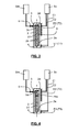
- an extrusion device 1 of a solid film comprises a cell 2 provided with a bottom 2a and side walls 2b.
- the extrusion device 1 also comprises an inlet orifice 3, in the cell 2, of a material intended to form the solid film, and an outlet orifice 4 of the solid film outside the cell 2, advantageously disposed in the background 2a.
- the inlet and outlet ports 4 and 4 may be located in positions other than those described in this example. However, it is preferable to place the inlet port 3 above the outlet port 4 to avoid natural convection problems.
- the inlet port 3 is connected to a distribution source Sm of the material.
- the bottom 2a is disposed at a first end of the cell 2 which extends along a longitudinal axis 2c.
- the cell 2 also has a ceiling 2d disposed in a second end of the cell 2, opposite the first end along the longitudinal axis 2c.
- Cell 2 delimits an internal volume Vc.
- internal volume Vc is meant a volume defined by the bottom 2a, the walls 2b side and 2d ceiling.
- the inlet orifice 3 is disposed in one of the side walls 2b, at the second end of the cell 2.
- the ceiling 2d is constituted by a rupture disc.
- rupture disc is meant a safety device which serves to protect the cell 2 against the risks of abnormal variations in pressure, within the cell 2.
- the rupture disc 2 may comprise a membrane watertight which breaks when a predetermined pressure of rupture is reached.
- the extrusion device 1 comprises a device for applying a first temperature T1 to the outlet orifice 4 of the cell 2 and a second temperature T2 in a first zone 6 of the cell 2 distinct from the outlet orifice 4.
- the first zone 6 of the cell 2 is disposed at the level of the ceiling 2d of the cell 2 and is distinct from the inlet orifice 3.
- the device for applying the first and second temperatures T1 and T2 may comprise first E1 and second E2 heat exchangers controlled by thermostats.
- the first and second heat exchangers E1 and E2 can be supplied by a source Sc of a cryogenic temperature fluid via first C1 and second C2 independent supply circuits.
- the application device of the first and second temperatures T1 and T2 is governed by a control circuit included in the extrusion device 1.
- the control circuit is configured to form a volume V1 of the solid phase material inside. of cell 2 at first.
- the first adjustment is chosen so that said volume V1 closes the outlet orifice 4.
- Said volume V1 closing the outlet orifice 4 is in position. contact with the bottom 2a and possibly the side walls 2b.
- the volume V1 may represent the entire internal volume Vc of the cell or only a portion of said internal volume Vc.
- the first adjustment is imposed on the device for applying the first and second temperatures T1 and T2 at the beginning of the introduction of the material intended to form the solid film via the inlet orifice 3.
- the material may be a material in gas phase and / or in liquid phase.
- the first temperature T1 is chosen to obtain the solidification of the material.
- the second temperature is chosen to leave the material in the fluid state (gaseous or liquid) at the inlet orifice 3 to obtain the filling of the cell 2.
- the difference between the first temperature T1 and the second temperature T2 during the first adjustment can vary between 0.1 K and 10 K.
- the difference between the first T1 and second T2 temperatures does not exceed one ten kelvin.
- the first adjustment imposed by the control circuit makes it possible firstly to close off the outlet orifice 4 by solidification of the material intended to form the solid film.
- the first adjustment also makes it possible to solidify a greater or lesser quantity of the material, after the closure of the outlet orifice 4, to form the volume V1 of the solid phase material.
- the control circuit is also configured to generate a temperature gradient in the volume V1.
- the temperature gradient is, in fact, applied between the outlet orifice 4 and the first zone 6 so as to generate a pressure in the volume V1 forcing the extrusion of the solid film through the outlet orifice 4.
- the gradient of temperature is accompanied by an expansion volume of the material which generates an increase in the pressure in the cell 2. This configuration simply forces the extrusion of the first material without using moving parts in the cell 2 by exploiting the pressure exerted on the ceiling and the side walls for have the extrusion through the outlet 4.
- control circuit is configured to completely fill the internal volume Vc of the cell 2 with the solid phase material.
- the volume V1 and the internal volume Vc of the cell 2 are identical.
- the first zone 6 of the cell 2 is disposed at the level of the ceiling 2d of the cell 2 and is distinct from the inlet orifice 3.
- the extrusion device 1 comprises, advantageously, a sealed enclosure 7 inside which the cell 2 is located so that the solid film extruded by the cell 2 is recovered in the sealed enclosure 7.
- the device extrusion 1 also comprises means for creating a vacuum in the sealed chamber 7.
- the vacuum created in the chamber 7 may be a secondary vacuum or an insulation vacuum, for example less than 0.1 Pa
- a heat shield 8 is interposed between the sealed enclosure 7 and the cell 2.
- the heat shield 8 envelopes the cell 2 leaving only the outlet orifice 4 uncovered.
- a heat shield makes it possible to limit the heat inputs. by radiation from the mechanical parts and thus to thermally isolate the cell 2.
- the cell 2 is in communication with the vacuum created in the sealed chamber 7 via the outlet orifice 4 before closing with the volume V1.
- the means for creating an isolation vacuum within the sealed chamber 7 can put the cell 2 under vacuum, before the introduction of the first material intended to form the solid film in the cell 2.
- the section of the outlet orifice 4 may be considered too weak to consider its use for pumping. It is therefore advantageous to add an auxiliary pumping device, connected to the outlet orifice 4, dedicated to the cell 2. This evacuation of the cell 2 makes it possible in particular to avoid contamination of the material introduced into the cell. cell 2, thus ensuring an improvement in the purity of the extruded solid film.
- the cell 2 may include a closure 5 for plugging the inlet port 3 to isolate the cell 2 before extrusion.
- the cell 2, in particular the closure 5, may comprise cooling means arranged at the inlet orifice 3.
- the closure 5 is a plug made by the material itself solidified in the inlet orifice 3 at the first setting to form volume V1.
- the closure 5 may be any known means for isolating the cell 2.
- the closure 5 may comprise a mechanical valve, or any other type of valve.
- the closure 5 comprises a valve configured to regulate the pressure in the cell 2. After the closure of the outlet orifice 4 by solidification of the material, the valve advantageously makes it possible to impose a predetermined pressure in the cell 2. The valve can thus regulate the pressure in the cell 2 to relax the constraints on the temperature settings within the cell 2 during the solidification of the material in the cell 2.
- the extrusion device 1 comprises a hydrogen injection source Sm (H 2 ) or deuterium (D 2 ) in the gas or liquid phase so as to extrude, respectively a solid film of hydrogen or deuterium.
- Sm hydrogen injection source
- D 2 deuterium
- the extrusion device 1 can be easily used in a proton therapy device or in a plasma creation device for applications in experimental physics.
- the Figures 2 to 4 illustrate a particular embodiment of a method of extruding a solid film by using the device according to the figure 1 .
- the extrusion process comprises a step of closing the outlet orifice 4.
- the cell 2 is initially evacuated.
- the outlet orifice 4 is closed by solidifying the material M1 in the outlet orifice 4.
- the volume V1 based on the material M1 is formed in the cell 2.
- the volume V1 is in contact with the side walls 2b and covers the outlet orifice 4.
- the volume V1 occupies the entire internal volume Vc of the cell 2.
- the inlet port 3 is closed and the extruder 1 generates a temperature gradient in the volume V1.
- the temperature gradient is generated so as to generate a pressure Pex in the cell 2 to force the extrusion of the solid film through the outlet orifice 4.
- the control circuit of the extruder 1 imposes a setting to the application device of the first and second temperatures T1 and T2 so as to create a temperature gradient between the first zone 6 and the outlet orifice 4.
- the temperature gradient allows the expansion of a portion Vd of the volume V1 of so as to generate the pressure Pex in the cell 2.
- the temperature gradient is chosen so that the generated pressure Pex forces the extrusion of the solid film through the outlet orifice 4.
- the second temperature T2 is modified so as to maintain a substantially constant pressure Pex at the outlet orifice 4, thereby ensuring continuity of the extrusion of the solid film.
- the first material M1 is advantageously a cryogenic fluid.
- cryogenic fluid is meant here the materials of Table 1 below.
- the Table 1 shows materials that can be extruded by the device as well as the values of the triple point temperatures of these materials.
- Table 1 Gas H 2 D 2 Born O 2 N 2 Ar CH 4 Triple point temperature (K) 13.95 18.73 24.5 54.4 63.14 84 89
- the closure of the outlet orifice 4 is achieved by maintaining, at first, the outlet orifice 4 at a first temperature T1i lower than the temperature T0 of the triple point of the cryogenic fluid .
- the first zone 6 distinct from the outlet orifice 4 is maintained at a second temperature T2i greater than the temperature T0 of the triple point of the cryogenic fluid, which makes it possible to leave the cryogenic fluid M1 in the fluid state (gaseous or liquid) at the inlet port 3. In other words, it prevents the solidification of the cryogenic fluid M1 at the inlet port 3 to allow the circulation of the cryogenic fluid to the outlet port 4.
- the introduction of the cryogenic fluid M1 into the cell 2 is advantageously carried out with a pressure P0 in the cell 2, to allow the solidification of the cryogenic fluid M1 at the outlet orifice 4.
- the valve of the closure 5 which regulates the flow rate of the cryogenic fluid M1 in the cell 2 can be set so as to obtain a pressure P0 in the cell 2.
- the value of the pressure P0 can also be chosen, so as to reduce the time required. for the solidification, at the temperature T1i, of the cryogenic fluid M1 in the outlet orifice 4.
- the pressure P0 is chosen so as to obtain an immediate solidification of the cryogenic fluid M1 in the outlet orifice 4.
- the difference between the temperature T0 of the triple point of the cryogenic fluid M1 and the first temperature T1i is between 2 and 5 K, and / or the difference between second temperature T2i and the temperature T0 of the triple point of the cryogenic fluid M1 is between 2 and 5 K.
- the temperature difference between the outlet orifice 4 and the first zone 6 advantageously makes it possible to solidify the cryogenic fluid M1 at the bottom 2a of the cell, and progressively fill the cell 2 with the cryogenic fluid M1 not solidified.
- the second temperature T2 in the first zone 6 is lowered and maintained at a temperature T2i 'substantially equal to the first temperature T1i, at the outlet orifice 4.
- the second temperature T2 is preferably maintained at a temperature of 2 to 5 K below the temperature T0 of the triple point of the cryogenic fluid M1.
- the reduction in the temperature of the first zone 6 advantageously allows the formation of the volume V1 by solidification of the cryogenic fluid M1.
- the volume V1 is in contact with the first zone 6, in other words, it covers the bottom 2a and is in contact with the side walls 2b.
- the decrease of the second temperature T2 is performed after the complete filling of the cell 2 by the cryogenic fluid M1.
- the volume V1 of the solidified cryogenic fluid M1 occupies the entire internal volume Vc of the cell 2.
- the inlet orifice 3 is closed and a temperature gradient is applied between the outlet orifice 4 and the first zone 6 to generate a pressure forcing the extrusion of the solid film.
- the closing of the inlet orifice 3 is achieved by the formation of said volume V1.
- the closing of the inlet port 3 can also be achieved by a plug formed by the material M1 solidified in the inlet port 3 during the formation of the volume V1.
- this closing of the inlet port 3 is achieved by closing the valve of the closure 5.
- the minimum pressure applied to a solid material in an extrusion chamber to extrude it is proportional to the shear strength of said material in the vicinity of the extrusion orifice. Furthermore, it is known that the shear strength of a solid phase material, in particular a solidified cryogenic fluid, decreases when its temperature is close to that of the triple point. Thus, it is advantageous to reduce the shear strength of the material M1 in the vicinity of the outlet port 4 before the generation of the pressure forcing the extrusion. In other words, the first temperature T1 at the outlet orifice 4 is maintained at a temperature substantially equal to the temperature T0 of the triple point of the material M1, during the extrusion of the solid film.
- the extrusion process described above advantageously makes it possible to generate a pressure within the cell 2 forcing the extrusion of a solid film without the use of a moving mechanical part in the cell 2 during the extrusion.
- the application of a temperature gradient between the outlet orifice 4 and the first zone 6 makes it possible to dilate a portion Vd of the volume V1 which thus acts as a virtual piston compressing the M1 material in the solid phase towards of the outlet orifice 4.
- the expansion intensity of the portion Vd of the volume V1, and therefore the extrusion rate of the solid film depends on the amplitude of the temperature gradient applied between the first zone 6 and the exit orifice 4.
- the extrusion of the solid film is carried out with a speed regulated by the adjustment of the second temperature T2 at the first zone 6 distinct from the outlet orifice 4.
- the modification of the second temperature T2 at the level of the first zone 6 makes it possible to modify the pressure exerted in the volume V1 and thus to change the extrusion speed of the solid film through the outlet orifice 4.
- the second temperature T2 is regulated with an accuracy of the order of one hundredth of a Kelvin, so as to control the solid film extrusion speed in an efficient and accurate manner.
- a cell having an internal volume of 10 cm 3 has been produced according to the invention.
- the cell was provided with an inlet port of about 1 mm in diameter and an outlet of a section of about 0.1 mm 2 .
- the first temperature T1 was set at about 13 K and the second temperature was set at about 20 K. This configuration of the cell and these conditions made it possible to extrude a hydrogen film.
- solid about 100 m long.
- the extruded solid hydrogen film had a thickness of about 100 ⁇ m and a width of about 1 mm.
Landscapes
- Engineering & Computer Science (AREA)
- Mechanical Engineering (AREA)
- Physics & Mathematics (AREA)
- Thermal Sciences (AREA)
- General Engineering & Computer Science (AREA)
- Health & Medical Sciences (AREA)
- Chemical Kinetics & Catalysis (AREA)
- Chemical & Material Sciences (AREA)
- Plasma & Fusion (AREA)
- High Energy & Nuclear Physics (AREA)
- Clinical Laboratory Science (AREA)
- Emergency Medicine (AREA)
- General Chemical & Material Sciences (AREA)
- Oil, Petroleum & Natural Gas (AREA)
- Oral & Maxillofacial Surgery (AREA)
- Extrusion Moulding Of Plastics Or The Like (AREA)
Abstract
Description
- L'invention concerne un dispositif d'extrusion d'un film solide.
- L'irradiation de certaines cibles solides par un laser pulsé de haute intensité est actuellement utilisée dans plusieurs domaines, notamment dans la recherche expérimentale en physique ou encore dans le domaine médical. En effet, il y a un intérêt considérable dans l'étude des plasmas produits par une irradiation laser de cibles solides, et susceptibles d'être utilisés dans des expériences de réactions directes en physique nucléaire. Par ailleurs, dans le domaine de la protonthérapie, un faisceau de protons peut être obtenu en focalisant un laser pulsé de haute intensité sur une cible, généralement en hydrogène ou en deutérium solide, à une cadence de l'ordre de 10 Hz.
- Ainsi, il est avantageux de disposer de systèmes permettant la production de cibles solides pures (LiH, H2, D2, ...) pouvant être utilisées à des températures cryogéniques. Pour la création de plasmas, par exemple dans les domaines cités ci-dessus, l'hydrogène pur ou l'un de ses isotopes comme le deutérium est souvent utilisé. En effet, les atomes d'hydrogène nécessitent moins de quantité d'énergie pour s'ioniser totalement, et perdent moins d'énergie à cause du rayonnement continu de freinage ou « bremsstrahlung » que tout autre élément.
- Des dispositifs produisant de l'hydrogène ou du deutérium solides utilisent essentiellement la technique d'extrusion. Ces dispositifs sont principalement intégrés dans les « tokamaks » pour alimenter les plasmas en combustible.
- L'article [« screw extruder for the centrifugal injector of hydrogen and deuterium pellets for the JT-60U tokamak » - I. V. Vinyar et al. - Instruments and experimental techniques, 2006, vol. 49, N° 5, pp. 726 - 731] décrit un dispositif d'extrusion muni d'une enceinte d'extrusion, et d'un échangeur thermique utilisant un flux d'hélium liquide refroidissant. L'échangeur thermique permet la condensation de l'isotope d'hydrogène introduit dans l'enceinte d'extrusion. Lors de l'extrusion, la température au sein de l'enceinte est comprise entre 11 et 14 K. L'enceinte d'extrusion comporte une vis qui sert à comprimer le matériau à extruder à des pressions de l'ordre de 5 à 10 MPa. La régulation de la vitesse de rotation de la vis permet ainsi l'extrusion de l'isotope d'hydrogène condensé dans le dispositif. Ce type de dispositif utilise le même principe que les dispositifs d'extrusion dans le domaine de la plasturgie. Cependant en plasturgie, la température du matériau à extruder est augmentée, alors que pour la création de plasmas, on travaille principalement à des températures cryogéniques et la température du matériau à extruder est généralement abaissée de manière à le condenser. Par températures cryogéniques, on entend des températures inférieures à environ 120 K.
- Un autre dispositif d'extrusion de deutérium (D2) est décrit dans l'article [« Solid deuterium fiber extruder » - J. D. Sethian et K. A. Gerber - Review of Scientific Instruments, avril 1987, 58(4), pp. 536 - 538]. Ce dispositif comporte un cylindre en cuivre exempt d'oxygène (OFC) relié à un cryostat à flux continu et des moyens de contrôle de la température du cylindre. Le cryostat utilise de l'hélium liquide et permet le refroidissement du cylindre comportant le deutérium jusqu'à 4,2 K. Un piston disposé à l'intérieur du cylindre comprime le deutérium dans le cylindre engendrant ainsi son extrusion.
- En outre, l'article [« A cryogenic fiber maker for continuous extrusion, - Aliaga-Rossel R. et al. - review of scientific instruments - AIP, MELVILLE, NY, US - vol. 69, n° 6 - (1998-06-01) - pages 2365-2368] décrit un dispositif d'extrusion comportant deux réservoirs disposés l'un au-dessus de l'autre. Le réservoir supérieur comporte une portion cylindrique reliée au réservoir inférieur par une portion conique. L'extrusion d'un film solide est réalisée en abaissant, dans un premier temps, la température du réservoir inférieur à une température permettant la solidification du gaz introduit dans le dispositif et en maintenant le réservoir supérieur à une température proche de la température de fusion pour obtenir un état liquide. Le gaz est ensuite introduit dans le réservoir supérieur jusqu'au remplissage du réservoir supérieur par le liquide. Enfin, en utilisant la canalisation externe d'alimentation en gaz, une pression extérieure d'extrusion est générée au sein des réservoirs pour extruder le film solide.
- L'extrusion de cibles solides, notamment en hydrogène ou en deutérium, nécessite la mise en oeuvre de pressions élevées à des températures cryogéniques. De ce fait, les dispositifs d'extrusion comportent généralement des moyens de refroidissement et des moyens supplémentaires pour générer une pression au sein de l'enceinte d'extrusion. Ces dispositifs sont complexes et difficiles à fabriquer et à intégrer à d'autres dispositifs comme les « tokamaks » ou les dispositifs de protonthérapie. De plus, un procédé d'extrusion utilisant ce type de dispositifs, nécessite un parfait contrôle de plusieurs paramètres relatifs à la température et à la pression au sein de l'enceinte d'extrusion, compliquant ainsi l'obtention de cibles solides pures.
- Dans certaines applications, il existe un besoin de fournir un dispositif d'extrusion de cibles solides pures, facile à réaliser, à utiliser, et à intégrer à d'autres dispositifs, et en particulier sans utiliser de pièces mobiles.
- On tend à satisfaire ce besoin en prévoyant un dispositif d'extrusion d'un film solide comportant une cellule munie d'un fond et de parois latérales, un orifice d'entrée, dans la cellule, d'un matériau destiné à former le film solide, un orifice de sortie du film solide de la cellule, et un dispositif d'application d'une première température à l'orifice de sortie de la cellule et d'une deuxième température dans une première zone de la cellule distincte de l'orifice de sortie. Avantageusement, l'orifice de sortie est situé en dessous de l'orifice d'entrée, dans le fond de la cellule. En outre, le dispositif d'extrusion comporte un circuit de commande imposant au dispositif d'application des première et seconde températures un premier réglage pour former un volume du matériau en phase solide à l'intérieur de la cellule, ledit volume obstruant l'orifice de sortie, et un deuxième réglage pour générer un gradient de température, entre l'orifice de sortie et la première zone de sorte à générer une pression dans la cellule forçant l'extrusion du film solide par l'orifice de sortie.
- On prévoit également un procédé d'extrusion d'un film solide comportant une étape d'obturation de l'orifice de sortie en solidifiant le matériau dans l'orifice de sortie, et une étape de formation d'un volume dudit matériau en phase solide, ledit volume recouvrant l'orifice de sortie. Ensuite, l'orifice d'entrée est fermé, puis un gradient de température dans ledit volume est généré de sorte à créer une pression dans la cellule pour forcer l'extrusion du film solide par l'orifice de sortie.
- D'autres avantages et caractéristiques ressortiront plus clairement de la description qui va suivre de modes particuliers de réalisation de l'invention donnés à titre d'exemples non limitatifs et représentés aux dessins annexés, dans lesquels :
- la
figure 1 représente schématiquement un dispositif d'extrusion ; - les
figures 2 à 4 représentent des étapes d'un procédé d'extrusion d'un film solide, en utilisant un dispositif selon lafigure 1 . - Comme représenté à la
figure 1 , un dispositif d'extrusion 1 d'un film solide comporte une cellule 2 munie d'un fond 2a et de parois latérales 2b. Le dispositif d'extrusion 1 comporte également un orifice d'entrée 3, dans la cellule 2, d'un matériau destiné à former le film solide, et un orifice de sortie 4 du film solide hors de la cellule 2, disposé avantageusement dans le fond 2a. Il est entendu que les orifices d'entrée 3 et de sortie 4 peuvent être situés en d'autres positions que celles décrites dans cet exemple. Cependant, il est préférable de placer l'orifice d'entrée 3 au-dessus de l'orifice de sortie 4, afin d'éviter des problèmes de convection naturelle. L'orifice d'entrée 3 est relié à une source de distribution Sm du matériau. Le fond 2a est disposé au niveau d'une première extrémité de la cellule 2 qui s'étend le long d'un axe longitudinal 2c. La cellule 2 comporte également un plafond 2d disposé dans une deuxième extrémité de la cellule 2, opposée à la première extrémité selon l'axe longitudinal 2c. La cellule 2 délimite un volume interne Vc. Par volume interne Vc, on entend un volume défini par le fond 2a, les parois latérales 2b et le plafond 2d. Préférentiellement, l'orifice d'entrée 3 est disposé dans l'une des parois latérales 2b, au niveau de la deuxième extrémité de la cellule 2. - De préférence, le plafond 2d est constitué par un disque de rupture. Par disque de rupture, on entend un dispositif de sécurité qui sert à protéger la cellule 2 contre les risques de variations anormales de la pression, au sein de la cellule 2. À titre d'exemple, le disque de rupture 2 peut comporter une membrane étanche qui se rompt lorsqu'une pression de rupture, préalablement fixée, est atteinte.
- Pour réguler la température au sein de la cellule 2, le dispositif d'extrusion 1 comporte un dispositif d'application d'une première température T1 à l'orifice de sortie 4 de la cellule 2 et d'une deuxième température T2 dans une première zone 6 de la cellule 2 distincte de l'orifice de sortie 4. Préférentiellement, la première zone 6 de la cellule 2 est disposée au niveau du plafond 2d de la cellule 2 et est distincte de l'orifice d'entrée 3. Le dispositif d'application des première et deuxième températures T1 et T2, peut comporter des premier E1 et second E2 échangeurs de chaleur commandés par des thermostats. Comme illustré à la
figure 1 , les premier et second échangeurs de chaleurs E1 et E2 peuvent être alimentés par une source Sc d'un fluide à température cryogénique via des premier C1 et second C2 circuits d'alimentation indépendants. - Le dispositif d'application des première et deuxième températures T1 et T2, est régi par un circuit de commande compris dans le dispositif d'extrusion 1. Le circuit de commande est configuré pour former un volume V1 du matériau en phase solide à l'intérieur de la cellule 2 dans un premier temps. Le premier réglage est choisi de manière à ce que ledit volume V1 obture l'orifice de sortie 4. Ledit volume V1 obturant l'orifice de sortie 4 est en contact avec le fond 2a et éventuellement les parois latérales 2b. Le volume V1 peut représenter tout le volume interne Vc de la cellule ou seulement une portion dudit volume interne Vc.
- Préférentiellement, le premier réglage est imposé au dispositif d'application des première et deuxième températures T1 et T2 au début de l'introduction du matériau destiné à former le film solide via l'orifice d'entrée 3. Le matériau peut être un matériau en phase gazeuse et/ou en phase liquide. La première température T1 est choisie pour obtenir la solidification du matériau. La deuxième température est choisie pour laisser le matériau à l'état fluide (gazeux ou liquide) à l'orifice d'entrée 3 pour obtenir le remplissage de la cellule 2. Selon le matériau destiné à former le film solide et la valeur de la première température T1, la différence entre la première température T1 et la deuxième température T2, lors du premier réglage, peut varier entre 0,1 K et 10 K. Avantageusement, l'écart entre les première T1 et seconde T2 températures ne dépasse pas une dizaine de kelvin. En effet, plus cet écart sera grand, plus le flux de chaleur se propageant de la zone chaude à la zone froide sera important, et plus il sera difficile de maintenir la première température T1 à la valeur fixée. Le premier réglage imposé par le circuit de commande permet dans un premier temps d'obturer l'orifice de sortie 4 par solidification du matériau destiné à former le film solide. Le premier réglage permet également de solidifier une quantité plus ou moins grande du matériau, après l'obturation de l'orifice de sortie 4, pour former le volume V1 du matériau en phase solide.
- Le circuit de commande est également configuré pour générer un gradient de température, dans le volume V1. Le gradient de température est, en fait, appliqué entre l'orifice de sortie 4 et la première zone 6 de sorte à générer une pression dans le volume V1 forçant l'extrusion du film solide par l'orifice de sortie 4. Le gradient de température est accompagné par une expansion volumique du matériau ce qui génère une augmentation de la pression dans la cellule 2. Cette configuration permet simplement de forcer l'extrusion du premier matériau sans utiliser de pièces mobiles dans la cellule 2 en exploitant la pression exercée sur le plafond et les parois latérales pour avoir l'extrusion par l'orifice de sortie 4.
- Avantageusement, le circuit de commande est configuré pour complètement remplir le volume interne Vc de la cellule 2 par le matériau en phase solide. Autrement dit, le volume V1 et le volume interne Vc de la cellule 2 sont identiques. Selon ce mode de réalisation, la première zone 6 de la cellule 2 est disposée au niveau du plafond 2d de la cellule 2 et est distincte de l'orifice d'entrée 3.
- Comme illustré à la
figure 1 , le dispositif d'extrusion 1 comporte, avantageusement, une enceinte étanche 7 à l'intérieur de laquelle se trouve la cellule 2 de manière à ce que le film solide extrudé par la cellule 2 soit récupéré dans l'enceinte étanche 7. Le dispositif d'extrusion 1 comporte également des moyens de création d'un vide dans l'enceinte étanche 7. Le vide créé dans l'enceinte 7 peut être un vide secondaire ou encore un vide d'isolement, par exemple inférieur à 0,1 Pa. Préférentiellement, un écran thermique 8 est interposé entre l'enceinte étanche 7 et la cellule 2. L'écran thermique 8 enveloppe la cellule 2 en laissant découvert uniquement l'orifice de sortie 4. Un écran thermique permet de limiter les apports de chaleur par rayonnement provenant des pièces mécaniques et donc d'isoler thermiquement la cellule 2. - La cellule 2 est en communication avec le vide créé dans l'enceinte étanche 7 via l'orifice de sortie 4 avant son obturation avec le volume V1. Ainsi, les moyens de création d'un vide d'isolement au sein de l'enceinte étanche 7 peuvent mettre la cellule 2 sous vide, avant l'introduction du premier matériau destiné à former le film solide dans la cellule 2. Cependant, la section de l'orifice de sortie 4 peut être considérée trop faible pour envisager son utilisation pour le pompage. Il est donc avantageux d'ajouter un dispositif de pompage annexe, connecté à l'orifice de sortie 4, dédié à la cellule 2. Cette mise sous vide de la cellule 2, permet en particulier d'éviter la contamination du matériau introduit dans la cellule 2, assurant ainsi une amélioration de la pureté du film solide extrudé.
- La cellule 2 peut comporter une fermeture 5 destinée à boucher l'orifice d'entrée 3 pour isoler la cellule 2 avant l'extrusion. La cellule 2, notamment la fermeture 5, peut comporter des moyens de refroidissement disposés au niveau de l'orifice d'entrée 3. Avantageusement, la fermeture 5 est un bouchon réalisé par le matériau lui-même solidifié dans l'orifice d'entrée 3 lors du premier réglage pour former le volume V1. Par ailleurs, la fermeture 5 peut être n'importe quel moyen connu permettant l'isolation de la cellule 2. Par exemple, la fermeture 5 peut comporter une vanne mécanique, ou tout autre type de vanne. De manière avantageuse, la fermeture 5 comporte une vanne configurée pour réguler la pression dans la cellule 2. Après l'obturation de l'orifice de sortie 4 par une solidification du matériau, la vanne permet avantageusement, d'imposer une pression prédéterminée dans la cellule 2. La vanne peut ainsi réguler la pression dans la cellule 2 pour relâcher les contraintes sur les réglages de la température au sein de la cellule 2 lors de la solidification du matériau dans la cellule 2.
- Avantageusement, le dispositif d'extrusion 1 comporte une source d'injection Sm d'hydrogène (H2) ou de deutérium (D2) en phase gazeuse ou liquide de manière à extruder, respectivement un film solide d'hydrogène ou de deutérium. Ainsi, le dispositif d'extrusion 1 peut être facilement utilisable dans un dispositif de protonthérapie ou encore dans un dispositif de création de plasma pour les applications en physique expérimentale.
- Les
figures 2 à 4 illustrent un mode particulier de mise en oeuvre d'un procédé d'extrusion d'un film solide en utilisant le dispositif selon lafigure 1 . Le procédé d'extrusion comporte une étape d'obturation de l'orifice de sortie 4. Préférentiellement, la cellule 2 est initialement mise sous vide. Comme illustré à lafigure 2 , l'orifice de sortie 4 est obturé en solidifiant le matériau M1 dans l'orifice de sortie 4. Après l'obturation de l'orifice de sortie 4, le volume V1 à base du matériau M1 est formé dans la cellule 2. Comme illustré à lafigure 3 , le volume V1 est en contact avec les parois latérales 2b et recouvre l'orifice de sortie 4. Avantageusement, le volume V1 occupe tout le volume interne Vc de la cellule 2. Après la formation d'un volume à base du matériau M1 en phase solide, l'orifice d'entrée 3 est fermé et le dispositif d'extrusion 1 génère un gradient de température dans le volume V1. Comme illustré à lafigure 4 , le gradient de température est généré de manière à engendrer une pression Pex dans la cellule 2 pour forcer l'extrusion du film solide par l'orifice de sortie 4. En effet, le circuit de commande du dispositif d'extrusion 1 impose un réglage au dispositif d'application des première et deuxième températures T1 et T2 de manière à créer un gradient de température entre la première zone 6 et l'orifice de sortie 4. Le gradient de température permet la dilatation d'une partie Vd du volume V1 de sorte à générer la pression Pex dans la cellule 2. Le gradient de température est choisi pour que la pression engendrée Pex force l'extrusion du film solide par l'orifice de sortie 4. Préférentiellement, au fur et à mesure de l'extrusion du film solide, la deuxième température T2 est modifiée de manière à garder une pression Pex sensiblement constante au niveau de l'orifice de sortie 4, assurant ainsi une continuité de l'extrusion du film solide. - Le premier matériau M1 est avantageusement, un fluide cryogénique. Par fluide cryogénique, on entend ici les matériaux du tableau 1 ci-dessous. Le tableau 1 représente des matériaux pouvant être extrudés par le dispositif ainsi que les valeurs des températures du point triple de ces matériaux.
Tableau 1 Gaz H2 D2 Ne O2 N2 Ar CH4 Température du point triple (K) 13,95 18,73 24,5 54,4 63,14 84 89 - Selon ce mode de mise en oeuvre, l'obturation de l'orifice de sortie 4 est réalisée en maintenant, dans un premier temps, l'orifice de sortie 4 à une première température T1i inférieure à la température T0 du point triple du fluide cryogénique. Par ailleurs, la première zone 6 distincte de l'orifice de sortie 4 est maintenue à une deuxième température T2i supérieure à la température T0 du point triple du fluide cryogénique, ce qui permet de laisser le fluide cryogénique M1 à l'état fluide (gazeux ou liquide) au niveau de l'orifice d'entrée 3. Autrement dit, on évite la solidification du fluide cryogénique M1 au niveau de l'orifice d'entrée 3 pour permettre la circulation du fluide cryogénique vers l'orifice de sortie 4. L'introduction du fluide cryogénique M1 dans la cellule 2 est avantageusement réalisée avec une pression P0 dans la cellule 2, pour permettre la solidification du fluide cryogénique M1 à l'orifice de sortie 4. À titre d'exemple, la vanne de la fermeture 5 qui régule le débit du fluide cryogénique M1 dans la cellule 2 peut être réglée de sorte à obtenir une pression P0 dans la cellule 2. La valeur de la pression P0 peut également être choisie, de manière à réduire le temps nécessaire pour la solidification, à la température T1i, du fluide cryogénique M1 dans l'orifice de sortie 4. Avantageusement, la pression P0 est choisie de manière à obtenir une solidification immédiate du fluide cryogénique M1 dans l'orifice de sortie 4. De préférence, la différence entre la température T0 du point triple du fluide cryogénique M1 et la première température T1i, est comprise entre 2 et 5 K, et/ou la différence entre la deuxième température T2i et la température T0 du point triple du fluide cryogénique M1 est comprise entre 2 et 5 K. La différence de température entre l'orifice de sortie 4 et la première zone 6 permet avantageusement de solidifier le fluide cryogénique M1 au niveau du fond 2a de la cellule, et de remplir progressivement la cellule 2 par le fluide cryogénique M1 non solidifié.
- Avantageusement, après l'obturation de l'orifice de sortie 4, la deuxième température T2 dans la première zone 6 est abaissée et maintenue à une température T2i' sensiblement égale à la première température T1i, à l'orifice de sortie 4. Autrement dit, la deuxième température T2 est préférentiellement, maintenue à une température de 2 à 5 K en dessous de la température T0 du point triple du fluide cryogénique M1. La diminution de la température de la première zone 6 permet avantageusement la formation du volume V1 par solidification du fluide cryogénique M1. Le volume V1 est en contact avec la première zone 6, autrement dit, il recouvre le fond 2a et il est en contact avec les parois latérales 2b.
- Préférentiellement, la diminution de la deuxième température T2 est réalisée après le remplissage complet de la cellule 2 par le fluide cryogénique M1. Ainsi, le volume V1 du fluide cryogénique M1 solidifié occupe tout le volume interne Vc de la cellule 2. Ensuite, l'orifice d'entrée 3 est fermé et un gradient de température est appliqué entre l'orifice de sortie 4 et la première zone 6 pour générer une pression forçant l'extrusion du film solide. Lorsque le volume V1 occupe tout le volume interne Vc de la cellule 2, la fermeture de l'orifice d'entrée 3 est réalisée par la formation dudit volume V1. Par ailleurs, comme cité ci-dessus, la fermeture de l'orifice d'entrée 3 peut également être réalisée par un bouchon formé par le matériau M1 solidifié dans l'orifice d'entrée 3 lors de la formation du volume V1. Avantageusement, cette obturation de l'orifice d'entrée 3 est réalisée en fermant la vanne de la fermeture 5.
- Dans le domaine d'extrusion de films solides, la pression minimale appliquée à un matériau solide dans une enceinte d'extrusion pour l'extruder, est proportionnelle à la résistance de cisaillement dudit matériau au voisinage de l'orifice d'extrusion. Par ailleurs, il est connu que la résistance de cisaillement d'un matériau en phase solide, notamment un fluide cryogénique solidifié, diminue lorsque sa température est proche de celle du point triple. Ainsi, il est avantageux de réduire la résistance de cisaillement du matériau M1 au voisinage de l'orifice de sortie 4 avant la génération de la pression forçant l'extrusion. Autrement dit, la première température T1 à l'orifice de sortie 4 est maintenue à une température sensiblement égale à la température T0 du point triple du matériau M1, lors de l'extrusion du film solide.
- Le procédé d'extrusion décrit ci-dessus permet avantageusement, de générer une pression au sein de la cellule 2 forçant l'extrusion d'un film solide sans l'utilisation d'une pièce mécanique mobile dans la cellule 2 durant l'extrusion. L'application d'un gradient de température entre l'orifice de sortie 4 et la première zone 6, permet la dilatation d'une portion Vd du volume V1 qui agit ainsi, comme un piston virtuel comprimant le matériau M1 en phase solide en direction de l'orifice de sortie 4. L'intensité de dilatation de la portion Vd du volume V1, et de ce fait, la vitesse d'extrusion du film solide dépend de l'amplitude du gradient de température appliqué entre la première zone 6 et l'orifice de sortie 4. Ainsi, il est possible d'asservir la deuxième température T2 à la vitesse d'extrusion du film solide. Autrement dit, l'extrusion du film solide est réalisée avec une vitesse régulée par le réglage de la deuxième température T2 à la première zone 6 distincte de l'orifice de sortie 4. En effet, lors de l'étape de l'extrusion, la modification de la deuxième température T2 au niveau de la première zone 6, permet de modifier la pression exercée dans le volume V1 et ainsi de modifier la vitesse d'extrusion du filme solide à travers l'orifice de sortie 4. Préférentiellement, la deuxième température T2 est régulée avec une précision de l'ordre du centième de kelvin, de sorte à contrôler la vitesse d'extrusion du film solide de manière efficace et précise.
- À titre d'exemple, une cellule ayant un volume interne de 10 cm3 a été réalisée selon l'invention. La cellule a été munie d'un orifice d'entrée d'environ 1 mm de diamètre et d'un orifice de sortie d'une section d'environ 0,1 mm2. En utilisant l'hydrogène comme matériau à extruder, la première température T1 a été fixée à environ 13 K et la seconde température a été fixée à environ 20 K. Cette configuration de la cellule et ces conditions ont permis d'extruder un film en hydrogène solide d'environ 100 m de long. Le film en hydrogène solide extrudé avait une épaisseur d'environ 100 µm et une largeur d'environ 1 mm.
Claims (13)
- Dispositif d'extrusion (1) d'un film solide comportant :- une cellule (2) munie d'un fond (2a) et de parois latérales (2b) ;- un orifice d'entrée (3), dans la cellule (2), d'un matériau destiné à former le film solide ;- un orifice de sortie (4) du film solide de la cellule (2) ;- un dispositif d'application d'une première température (T1) à l'orifice de sortie (4) de la cellule (2) et d'une deuxième température (T2) dans une première zone (6) de la cellule (2) distincte de l'orifice de sortie (4) ;- un circuit de commande imposant au dispositif d'application des première (T1) et seconde (T2) températures :+ un premier réglage pour former un volume (V1) du matériau en phase solide à l'intérieur de la cellule (2), ledit volume obstruant l'orifice de sortie (4) ;+ un deuxième réglage pour générer un gradient de température, entre l'orifice de sortie (4) et la première zone (6) de sorte à générer une pression dans la cellule (2) forçant l'extrusion du film solide par l'orifice de sortie (4).
- Dispositif d'extrusion (1) selon la revendication 1, caractérisé en ce que l'orifice de sortie (4) est situé en dessous de l'orifice d'entrée (3).
- Dispositif d'extrusion (1) selon l'une des revendications 1 et 2, caractérisé en ce que le circuit de commande impose au dispositif d'application des première (T1) et seconde (T2) températures un troisième réglage pour complètement remplir le volume interne (Vc) de la cellule (2) par ledit matériau en phase solide.
- Dispositif d'extrusion (1) selon l'une quelconque des revendications 1 à 3, caractérisé en ce qu'il comporte une enceinte étanche (7) à l'intérieur de laquelle se trouve la cellule (2) et en ce qu'il comporte des moyens de création d'un vide dans l'enceinte étanche (7), le film solide extrudé par la cellule (2) étant récupéré dans l'enceinte étanche (7).
- Dispositif d'extrusion (1) selon l'une quelconque des revendications 1 à 4, caractérisé en ce qu'il comporte une source d'injection (Sm) d'hydrogène ou de deutérium en phase gazeuse ou liquide de manière à extruder, respectivement un film solide d'hydrogène ou de deutérium.
- Dispositif d'extrusion (1) selon l'une quelconque des revendications 1 à 5, caractérisé en ce que la cellule (2) comporte une fermeture (5) de l'orifice d'entrée (3).
- Dispositif d'extrusion (1) selon la revendication 6, caractérisé en ce que la fermeture (5) comporte une vanne configurée pour réguler la pression dans la cellule (2).
- Dispositif d'extrusion (1) selon l'une des revendications 6 et 7, caractérisé en ce que la fermeture (5) comporte des moyens de refroidissement.
- Procédé d'extrusion d'un film solide utilisant un dispositif selon l'une quelconque des revendications 1 à 8, caractérisé en ce qu'il comporte les étapes successives suivantes :- obturer l'orifice de sortie (4) en solidifiant le matériau (M1) dans l'orifice de sortie (4) ;- former un volume (V1) du matériau (M1) en phase solide, ledit volume (V1) recouvrant l'orifice de sortie (4) ;- fermer l'orifice d'entrée (3) ;- générer un gradient de température dans ledit volume (V1) de manière à générer une pression (Pex) dans la cellule (2) pour forcer l'extrusion du film solide par l'orifice de sortie (4).
- Procédé d'extrusion selon la revendication 9, caractérisé en ce que le matériau (M1) est un fluide cryogénique et en ce que l'obturation de l'orifice de sortie (4) comporte les étapes suivantes :- maintenir l'orifice de sortie (4) à une première température (T1) inférieure à la température (T0) du point triple du fluide cryogénique (M1), et une première zone (6) des parois latérales (2b) à une deuxième température (T2) supérieure à la température (T0) du point triple du fluide cryogénique (M1) ;- introduire le fluide cryogénique (M1) dans la cellule (2) avec une pression (P0) dans la cellule (2), permettant la solidification du fluide cryogénique (M1) à l'orifice de sortie (4).
- Procédé d'extrusion selon la revendication 10, caractérisé en ce qu'après l'obturation de l'orifice de sortie (4), la deuxième température (T2) dans la première zone (6) est maintenue à une température sensiblement égale à la première température (T1) à l'orifice de sortie (4) de manière à former le volume (V1) à base du fluide cryogénique (M1) solidifié, la première zone (6) étant en contact avec le volume (V1).
- Procédé d'extrusion selon l'une quelconque des revendications 9 à 11, caractérisé en ce qu'avant la génération du gradient de température pour forcer l'extrusion du film solide, la première température (T1) à l'orifice de sortie (4) est maintenue à une température sensiblement égale à la température (T0) du point triple du matériau (M1).
- Procédé d'extrusion selon l'une quelconque des revendications 9 à 12, caractérisé en ce que le film solide est extrudé avec une vitesse régulée par le réglage de la deuxième température (T2) à la première zone (6) de la cellule (2).
Applications Claiming Priority (1)
| Application Number | Priority Date | Filing Date | Title |
|---|---|---|---|
| FR1201883A FR2993043B1 (fr) | 2012-07-04 | 2012-07-04 | Dispositif et procede d'extrusion d'un corps solide |
Publications (2)
| Publication Number | Publication Date |
|---|---|
| EP2682695A1 true EP2682695A1 (fr) | 2014-01-08 |
| EP2682695B1 EP2682695B1 (fr) | 2020-09-30 |
Family
ID=47553112
Family Applications (1)
| Application Number | Title | Priority Date | Filing Date |
|---|---|---|---|
| EP13354022.9A Active EP2682695B1 (fr) | 2012-07-04 | 2013-07-02 | Dispositif et procédé d'extrusion d'un corps solide |
Country Status (3)
| Country | Link |
|---|---|
| US (1) | US9873214B2 (fr) |
| EP (1) | EP2682695B1 (fr) |
| FR (1) | FR2993043B1 (fr) |
Citations (1)
| Publication number | Priority date | Publication date | Assignee | Title |
|---|---|---|---|---|
| US20040071266A1 (en) * | 2002-10-11 | 2004-04-15 | Orsini Rocco A. | Low vapor pressure, low debris solid target for EUV production |
Family Cites Families (1)
| Publication number | Priority date | Publication date | Assignee | Title |
|---|---|---|---|---|
| JP4714910B2 (ja) * | 2000-11-09 | 2011-07-06 | 独立行政法人 日本原子力研究開発機構 | 重水素氷の連続生成・装填装置および方法 |
-
2012
- 2012-07-04 FR FR1201883A patent/FR2993043B1/fr not_active Expired - Fee Related
-
2013
- 2013-07-02 EP EP13354022.9A patent/EP2682695B1/fr active Active
- 2013-07-03 US US13/934,917 patent/US9873214B2/en active Active
Patent Citations (1)
| Publication number | Priority date | Publication date | Assignee | Title |
|---|---|---|---|---|
| US20040071266A1 (en) * | 2002-10-11 | 2004-04-15 | Orsini Rocco A. | Low vapor pressure, low debris solid target for EUV production |
Non-Patent Citations (7)
| Title |
|---|
| 1. V. VINYAR ET AL.: "screw extruder for the centrifugal injector of hydrogen and deuterium pellets for the JT-60U tokamak", INSTRUMENTS AND EXPERIMENTAL TECHNIQUES, vol. 49, no. 5, 2006, pages 726 - 731 |
| ALIAGA-ROSSEL R ET AL: "A cryogenic fiber maker for continuous extrusion", REVIEW OF SCIENTIFIC INSTRUMENTS, AIP, MELVILLE, NY, US, vol. 69, no. 6, 1 June 1998 (1998-06-01), pages 2365 - 2368, XP012036623, ISSN: 0034-6748, DOI: 10.1063/1.1148945 * |
| ALIAGA-ROSSEL R. ET AL.: "A cryogenic fiber maker for continuous extrusion", REVIEW OF SCIENTIFIC INSTRUMENTS, vol. 69, no. 6, 1 June 1998 (1998-06-01), pages 2365 - 2368 |
| COMBS S K ET AL: "Extruder system for high-throughput/steady-state hydrogen ice supply and application for pellet fueling of reactor-scale fusion experiments", REVIEW OF SCIENTIFIC INSTRUMENTS, AIP, MELVILLE, NY, US, vol. 69, no. 11, 1 November 1998 (1998-11-01), pages 4012 - 4013, XP012036146, ISSN: 0034-6748, DOI: 10.1063/1.1149216 * |
| J. D. SETHIAN ET AL: "Solid deuterium fiber extruder", REVIEW OF SCIENTIFIC INSTRUMENTS, vol. 58, no. 4, 1 January 1987 (1987-01-01), pages 536, XP055065527, ISSN: 0034-6748, DOI: 10.1063/1.1139265 * |
| J. D. SETHIAN; K. A. GERBER: "Solid deuterium fiber extruder", REVIEW OF SCIENTIFIC INSTRUMENTS, vol. 58, no. 4, April 1987 (1987-04-01), pages 536 - 538 |
| VINYAR I V ET AL: "A screw extruder for the centrifugal injector of hydrogen and deuterium pellets for the JT-60U tokamak", INSTRUMENTS AND EXPERIMENTAL TECHNIQUES, KLUWER ACADEMIC PUBLISHERS-PLENUM PUBLISHERS, NE, vol. 49, no. 5, 1 October 2006 (2006-10-01), pages 726 - 731, XP019435046, ISSN: 1608-3180, DOI: 10.1134/S0020441206050216 * |
Also Published As
| Publication number | Publication date |
|---|---|
| US20140008829A1 (en) | 2014-01-09 |
| FR2993043B1 (fr) | 2014-07-11 |
| FR2993043A1 (fr) | 2014-01-10 |
| US9873214B2 (en) | 2018-01-23 |
| EP2682695B1 (fr) | 2020-09-30 |
Similar Documents
| Publication | Publication Date | Title |
|---|---|---|
| Garcia et al. | Continuous production of a thin ribbon of solid hydrogen | |
| EP0567387B1 (fr) | Dispositif de compactage à chaud pour la fabrication de pièces nécessitant des montées en pression et en température simultanées | |
| EP3560302B1 (fr) | Système de ciblerie à gaz pour production de radio-isotopes | |
| CA2501244C (fr) | Piece a circuit de transport de fluide et sa fabrication | |
| FR2473248A1 (fr) | Generateur de gaz ionise a tres haute pression et tres haute temperature | |
| EP2682695B1 (fr) | Dispositif et procédé d'extrusion d'un corps solide | |
| FR3083465A1 (fr) | Procede et dispositif de granulation | |
| EP2633527B1 (fr) | Dispositif destiné à la production de radioisotopes | |
| EP2581914B1 (fr) | Procédé et installation pour la production d'un radioisotope | |
| EP1588591B1 (fr) | Dispositif d' injection d' un flux de gaz supersonique pulse | |
| EP4552824A1 (fr) | Vis d'extrusion, extrudeuse et procédé de fabrication d'un câble électrique par extrusion d'une composition à base d'un polymère de propylène avec une vis d'extrusion à débit amélioré | |
| CA3215673A1 (fr) | Dispositif de compression d'un fluide stocke sous la forme d'un liquide cryogenique, et procede de fabrication associe | |
| Astbury et al. | In-situ formation of solidified hydrogen thin-membrane targets using a pulse tube cryocooler | |
| BE1019293A5 (fr) | Procede et dispositif de moulage de pieces en materiau composite. | |
| CN113747644B (zh) | 利用离子分离抑制黑腔辐射源腔壁等离子体膨胀的方法 | |
| EP3393739B1 (fr) | Dispositif de régulation de la température d'un moule par diode vcsel | |
| JP4714910B2 (ja) | 重水素氷の連続生成・装填装置および方法 | |
| FR3002982A1 (fr) | Dispositif de modulation de section d'ejection de gaz. | |
| FR2995364A1 (fr) | Dispositif de propulsion hybride anaerobie a carburant presente sous de forme de solides divises | |
| TW202219386A (zh) | 泵浦 | |
| Pillet | PulsePower—Public-domain release of open specifications for BN-diamondoid capacitor, self-healing Cu-graphene busbar and opto-FMC | |
| Périn et al. | Solid hydrogen target for laser driven proton acceleration | |
| Polistchook et al. | Arc ignition at heating of graphite by fixed current | |
| Viniar et al. | A large-scale prototype of a tritium pellet injector for the ITER international tokamak | |
| BE1031594A1 (fr) | Dispositif de production de dihydrogène comportant un séparateur combiné multiétage |
Legal Events
| Date | Code | Title | Description |
|---|---|---|---|
| PUAI | Public reference made under article 153(3) epc to a published international application that has entered the european phase |
Free format text: ORIGINAL CODE: 0009012 |
|
| AK | Designated contracting states |
Kind code of ref document: A1 Designated state(s): AL AT BE BG CH CY CZ DE DK EE ES FI FR GB GR HR HU IE IS IT LI LT LU LV MC MK MT NL NO PL PT RO RS SE SI SK SM TR |
|
| AX | Request for extension of the european patent |
Extension state: BA ME |
|
| 17P | Request for examination filed |
Effective date: 20140707 |
|
| RBV | Designated contracting states (corrected) |
Designated state(s): AL AT BE BG CH CY CZ DE DK EE ES FI FR GB GR HR HU IE IS IT LI LT LU LV MC MK MT NL NO PL PT RO RS SE SI SK SM TR |
|
| GRAP | Despatch of communication of intention to grant a patent |
Free format text: ORIGINAL CODE: EPIDOSNIGR1 |
|
| STAA | Information on the status of an ep patent application or granted ep patent |
Free format text: STATUS: GRANT OF PATENT IS INTENDED |
|
| INTG | Intention to grant announced |
Effective date: 20200424 |
|
| GRAS | Grant fee paid |
Free format text: ORIGINAL CODE: EPIDOSNIGR3 |
|
| GRAA | (expected) grant |
Free format text: ORIGINAL CODE: 0009210 |
|
| STAA | Information on the status of an ep patent application or granted ep patent |
Free format text: STATUS: THE PATENT HAS BEEN GRANTED |
|
| AK | Designated contracting states |
Kind code of ref document: B1 Designated state(s): AL AT BE BG CH CY CZ DE DK EE ES FI FR GB GR HR HU IE IS IT LI LT LU LV MC MK MT NL NO PL PT RO RS SE SI SK SM TR |
|
| REG | Reference to a national code |
Ref country code: GB Ref legal event code: FG4D Free format text: NOT ENGLISH Ref country code: CH Ref legal event code: EP |
|
| REG | Reference to a national code |
Ref country code: AT Ref legal event code: REF Ref document number: 1319213 Country of ref document: AT Kind code of ref document: T Effective date: 20201015 Ref country code: DE Ref legal event code: R096 Ref document number: 602013072906 Country of ref document: DE |
|
| REG | Reference to a national code |
Ref country code: IE Ref legal event code: FG4D Free format text: LANGUAGE OF EP DOCUMENT: FRENCH |
|
| PG25 | Lapsed in a contracting state [announced via postgrant information from national office to epo] |
Ref country code: HR Free format text: LAPSE BECAUSE OF FAILURE TO SUBMIT A TRANSLATION OF THE DESCRIPTION OR TO PAY THE FEE WITHIN THE PRESCRIBED TIME-LIMIT Effective date: 20200930 Ref country code: FI Free format text: LAPSE BECAUSE OF FAILURE TO SUBMIT A TRANSLATION OF THE DESCRIPTION OR TO PAY THE FEE WITHIN THE PRESCRIBED TIME-LIMIT Effective date: 20200930 Ref country code: GR Free format text: LAPSE BECAUSE OF FAILURE TO SUBMIT A TRANSLATION OF THE DESCRIPTION OR TO PAY THE FEE WITHIN THE PRESCRIBED TIME-LIMIT Effective date: 20201231 Ref country code: SE Free format text: LAPSE BECAUSE OF FAILURE TO SUBMIT A TRANSLATION OF THE DESCRIPTION OR TO PAY THE FEE WITHIN THE PRESCRIBED TIME-LIMIT Effective date: 20200930 Ref country code: BG Free format text: LAPSE BECAUSE OF FAILURE TO SUBMIT A TRANSLATION OF THE DESCRIPTION OR TO PAY THE FEE WITHIN THE PRESCRIBED TIME-LIMIT Effective date: 20201230 Ref country code: NO Free format text: LAPSE BECAUSE OF FAILURE TO SUBMIT A TRANSLATION OF THE DESCRIPTION OR TO PAY THE FEE WITHIN THE PRESCRIBED TIME-LIMIT Effective date: 20201230 |
|
| REG | Reference to a national code |
Ref country code: AT Ref legal event code: MK05 Ref document number: 1319213 Country of ref document: AT Kind code of ref document: T Effective date: 20200930 |
|
| PG25 | Lapsed in a contracting state [announced via postgrant information from national office to epo] |
Ref country code: RS Free format text: LAPSE BECAUSE OF FAILURE TO SUBMIT A TRANSLATION OF THE DESCRIPTION OR TO PAY THE FEE WITHIN THE PRESCRIBED TIME-LIMIT Effective date: 20200930 Ref country code: LV Free format text: LAPSE BECAUSE OF FAILURE TO SUBMIT A TRANSLATION OF THE DESCRIPTION OR TO PAY THE FEE WITHIN THE PRESCRIBED TIME-LIMIT Effective date: 20200930 |
|
| REG | Reference to a national code |
Ref country code: NL Ref legal event code: MP Effective date: 20200930 |
|
| REG | Reference to a national code |
Ref country code: LT Ref legal event code: MG4D |
|
| PG25 | Lapsed in a contracting state [announced via postgrant information from national office to epo] |
Ref country code: CZ Free format text: LAPSE BECAUSE OF FAILURE TO SUBMIT A TRANSLATION OF THE DESCRIPTION OR TO PAY THE FEE WITHIN THE PRESCRIBED TIME-LIMIT Effective date: 20200930 Ref country code: EE Free format text: LAPSE BECAUSE OF FAILURE TO SUBMIT A TRANSLATION OF THE DESCRIPTION OR TO PAY THE FEE WITHIN THE PRESCRIBED TIME-LIMIT Effective date: 20200930 Ref country code: RO Free format text: LAPSE BECAUSE OF FAILURE TO SUBMIT A TRANSLATION OF THE DESCRIPTION OR TO PAY THE FEE WITHIN THE PRESCRIBED TIME-LIMIT Effective date: 20200930 Ref country code: SM Free format text: LAPSE BECAUSE OF FAILURE TO SUBMIT A TRANSLATION OF THE DESCRIPTION OR TO PAY THE FEE WITHIN THE PRESCRIBED TIME-LIMIT Effective date: 20200930 Ref country code: LT Free format text: LAPSE BECAUSE OF FAILURE TO SUBMIT A TRANSLATION OF THE DESCRIPTION OR TO PAY THE FEE WITHIN THE PRESCRIBED TIME-LIMIT Effective date: 20200930 Ref country code: PT Free format text: LAPSE BECAUSE OF FAILURE TO SUBMIT A TRANSLATION OF THE DESCRIPTION OR TO PAY THE FEE WITHIN THE PRESCRIBED TIME-LIMIT Effective date: 20210201 Ref country code: NL Free format text: LAPSE BECAUSE OF FAILURE TO SUBMIT A TRANSLATION OF THE DESCRIPTION OR TO PAY THE FEE WITHIN THE PRESCRIBED TIME-LIMIT Effective date: 20200930 |
|
| PG25 | Lapsed in a contracting state [announced via postgrant information from national office to epo] |
Ref country code: PL Free format text: LAPSE BECAUSE OF FAILURE TO SUBMIT A TRANSLATION OF THE DESCRIPTION OR TO PAY THE FEE WITHIN THE PRESCRIBED TIME-LIMIT Effective date: 20200930 Ref country code: IS Free format text: LAPSE BECAUSE OF FAILURE TO SUBMIT A TRANSLATION OF THE DESCRIPTION OR TO PAY THE FEE WITHIN THE PRESCRIBED TIME-LIMIT Effective date: 20210130 Ref country code: ES Free format text: LAPSE BECAUSE OF FAILURE TO SUBMIT A TRANSLATION OF THE DESCRIPTION OR TO PAY THE FEE WITHIN THE PRESCRIBED TIME-LIMIT Effective date: 20200930 Ref country code: AT Free format text: LAPSE BECAUSE OF FAILURE TO SUBMIT A TRANSLATION OF THE DESCRIPTION OR TO PAY THE FEE WITHIN THE PRESCRIBED TIME-LIMIT Effective date: 20200930 Ref country code: AL Free format text: LAPSE BECAUSE OF FAILURE TO SUBMIT A TRANSLATION OF THE DESCRIPTION OR TO PAY THE FEE WITHIN THE PRESCRIBED TIME-LIMIT Effective date: 20200930 |
|
| PG25 | Lapsed in a contracting state [announced via postgrant information from national office to epo] |
Ref country code: SK Free format text: LAPSE BECAUSE OF FAILURE TO SUBMIT A TRANSLATION OF THE DESCRIPTION OR TO PAY THE FEE WITHIN THE PRESCRIBED TIME-LIMIT Effective date: 20200930 |
|
| REG | Reference to a national code |
Ref country code: DE Ref legal event code: R097 Ref document number: 602013072906 Country of ref document: DE |
|
| PLBE | No opposition filed within time limit |
Free format text: ORIGINAL CODE: 0009261 |
|
| STAA | Information on the status of an ep patent application or granted ep patent |
Free format text: STATUS: NO OPPOSITION FILED WITHIN TIME LIMIT |
|
| PG25 | Lapsed in a contracting state [announced via postgrant information from national office to epo] |
Ref country code: DK Free format text: LAPSE BECAUSE OF FAILURE TO SUBMIT A TRANSLATION OF THE DESCRIPTION OR TO PAY THE FEE WITHIN THE PRESCRIBED TIME-LIMIT Effective date: 20200930 |
|
| 26N | No opposition filed |
Effective date: 20210701 |
|
| PG25 | Lapsed in a contracting state [announced via postgrant information from national office to epo] |
Ref country code: IT Free format text: LAPSE BECAUSE OF FAILURE TO SUBMIT A TRANSLATION OF THE DESCRIPTION OR TO PAY THE FEE WITHIN THE PRESCRIBED TIME-LIMIT Effective date: 20200930 |
|
| PG25 | Lapsed in a contracting state [announced via postgrant information from national office to epo] |
Ref country code: SI Free format text: LAPSE BECAUSE OF FAILURE TO SUBMIT A TRANSLATION OF THE DESCRIPTION OR TO PAY THE FEE WITHIN THE PRESCRIBED TIME-LIMIT Effective date: 20200930 |
|
| REG | Reference to a national code |
Ref country code: CH Ref legal event code: PL |
|
| PG25 | Lapsed in a contracting state [announced via postgrant information from national office to epo] |
Ref country code: MC Free format text: LAPSE BECAUSE OF FAILURE TO SUBMIT A TRANSLATION OF THE DESCRIPTION OR TO PAY THE FEE WITHIN THE PRESCRIBED TIME-LIMIT Effective date: 20200930 |
|
| REG | Reference to a national code |
Ref country code: BE Ref legal event code: MM Effective date: 20210731 |
|
| PG25 | Lapsed in a contracting state [announced via postgrant information from national office to epo] |
Ref country code: LI Free format text: LAPSE BECAUSE OF NON-PAYMENT OF DUE FEES Effective date: 20210731 Ref country code: CH Free format text: LAPSE BECAUSE OF NON-PAYMENT OF DUE FEES Effective date: 20210731 |
|
| PG25 | Lapsed in a contracting state [announced via postgrant information from national office to epo] |
Ref country code: IS Free format text: LAPSE BECAUSE OF FAILURE TO SUBMIT A TRANSLATION OF THE DESCRIPTION OR TO PAY THE FEE WITHIN THE PRESCRIBED TIME-LIMIT Effective date: 20210130 Ref country code: LU Free format text: LAPSE BECAUSE OF NON-PAYMENT OF DUE FEES Effective date: 20210702 |
|
| PG25 | Lapsed in a contracting state [announced via postgrant information from national office to epo] |
Ref country code: IE Free format text: LAPSE BECAUSE OF NON-PAYMENT OF DUE FEES Effective date: 20210702 Ref country code: BE Free format text: LAPSE BECAUSE OF NON-PAYMENT OF DUE FEES Effective date: 20210731 |
|
| PG25 | Lapsed in a contracting state [announced via postgrant information from national office to epo] |
Ref country code: HU Free format text: LAPSE BECAUSE OF FAILURE TO SUBMIT A TRANSLATION OF THE DESCRIPTION OR TO PAY THE FEE WITHIN THE PRESCRIBED TIME-LIMIT; INVALID AB INITIO Effective date: 20130702 |
|
| PG25 | Lapsed in a contracting state [announced via postgrant information from national office to epo] |
Ref country code: CY Free format text: LAPSE BECAUSE OF FAILURE TO SUBMIT A TRANSLATION OF THE DESCRIPTION OR TO PAY THE FEE WITHIN THE PRESCRIBED TIME-LIMIT Effective date: 20200930 |
|
| PG25 | Lapsed in a contracting state [announced via postgrant information from national office to epo] |
Ref country code: MK Free format text: LAPSE BECAUSE OF FAILURE TO SUBMIT A TRANSLATION OF THE DESCRIPTION OR TO PAY THE FEE WITHIN THE PRESCRIBED TIME-LIMIT Effective date: 20200930 |
|
| PG25 | Lapsed in a contracting state [announced via postgrant information from national office to epo] |
Ref country code: MT Free format text: LAPSE BECAUSE OF FAILURE TO SUBMIT A TRANSLATION OF THE DESCRIPTION OR TO PAY THE FEE WITHIN THE PRESCRIBED TIME-LIMIT Effective date: 20200930 |
|
| PGFP | Annual fee paid to national office [announced via postgrant information from national office to epo] |
Ref country code: DE Payment date: 20250722 Year of fee payment: 13 |
|
| PGFP | Annual fee paid to national office [announced via postgrant information from national office to epo] |
Ref country code: GB Payment date: 20250724 Year of fee payment: 13 |
|
| PGFP | Annual fee paid to national office [announced via postgrant information from national office to epo] |
Ref country code: FR Payment date: 20250722 Year of fee payment: 13 |
|
| PG25 | Lapsed in a contracting state [announced via postgrant information from national office to epo] |
Ref country code: TR Free format text: LAPSE BECAUSE OF FAILURE TO SUBMIT A TRANSLATION OF THE DESCRIPTION OR TO PAY THE FEE WITHIN THE PRESCRIBED TIME-LIMIT Effective date: 20200930 |